

Page 1
Air Gap Adapter Specification Submittal Sheet
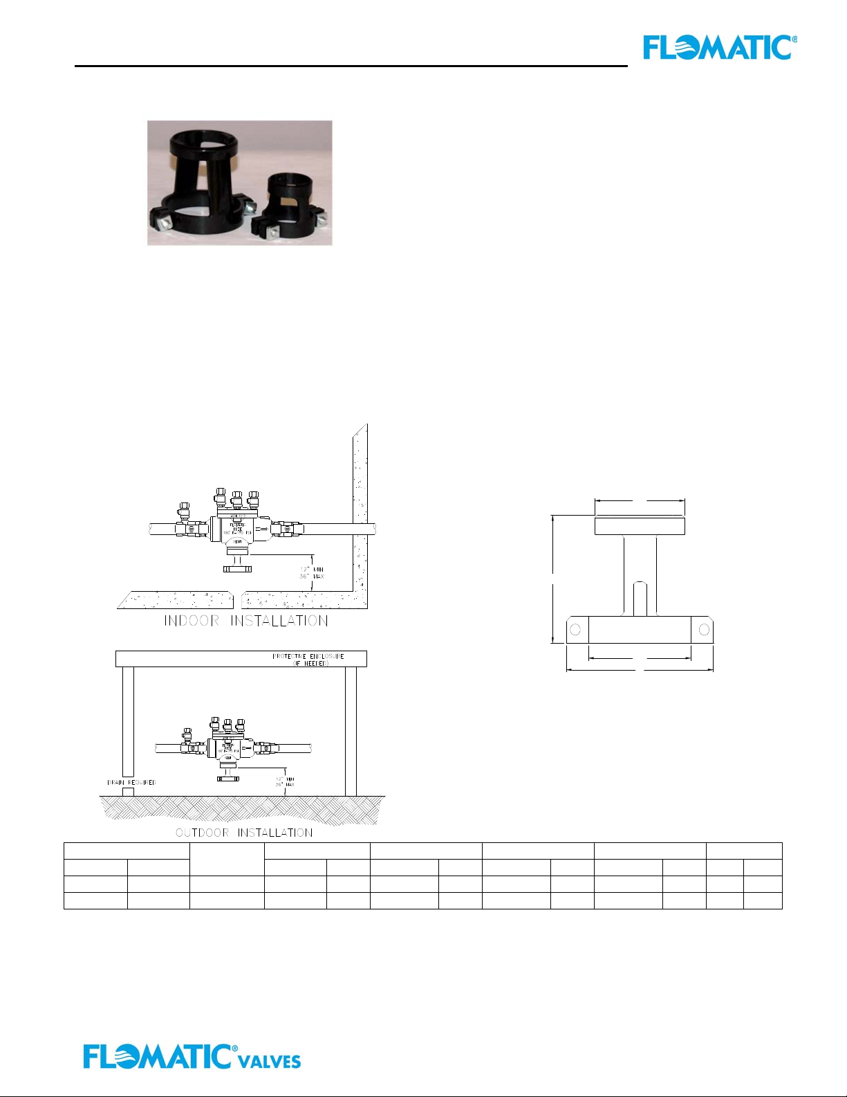
Model AGA (1/2” thru 2”)
FEATURES:
Sizes: □½” – ¾” □¾” – 2”
STANDARDS COMPLIANCE:
● ANSI/ASME A112.1.2
MATERIALS:
Body Polycarbonate
Fasteners Stainless Steel, 300 series
Size ØA B ØC Ref D Weight
inch mm
Part #
inch mm inch mm inch mm inch mm lbs kg
APPLICATION:
The Flomatic model AGA is designed for use with ½”
thru 2” models RPZ, RPZE, RPZE II and RPDA
TYPICAL INSTALLATION:
Local codes shall govern installation requirements. To
be installed in accordance with the manufacturers
instructions.
SUGGESTED DRAIN PIPE SIZE:
8273599 – 1-1/4” Steel schedule 40 & 80
1-1/4” PVC schedule 40 & 80
1-1/2” Copper Type K
8273500 - 2” Steel schedule 40 & 80
2” PVC schedule 40 & 80
2-1/2” Copper Type K
B
½” - ¾ 15 - 20 8273599 1-27/64 36 1-45/64 43 1-1/2 38 2-31/64 63 .1 .36
¾” – 2” 20 - 50 8273500 2-11/64 55 2-25/32 71 2-1/2 64 3-35/64 91 .1 .45
WARRANTY: Flomatic valves are guaranteed against defects of materials or workmanship when used for the services
recommended. If in any recommended service, a defect develops due to material or workmanship, and the device is returned,
freight prepaid, to Flomatic Corporation within 12 months from the date of purchase, it will be repaired or replaced free of charge.
Flomatic Corporations’ liability shall be limited to our agreement to repair or replace the valve only.
Flomatic Corporation
ØA
ØC
D
Flomatic Corporation, 15 Pruyn’s Island, Glens Falls, New York 12801
Phone: 518-761-9797 Fax: 518-761-9798 www.flomatic.com
October 3,2006 Rev. 3 (6/11)
Specification Sheet AGA-2
Page 2
Air Gap Adapter Specification Submittal Sheet
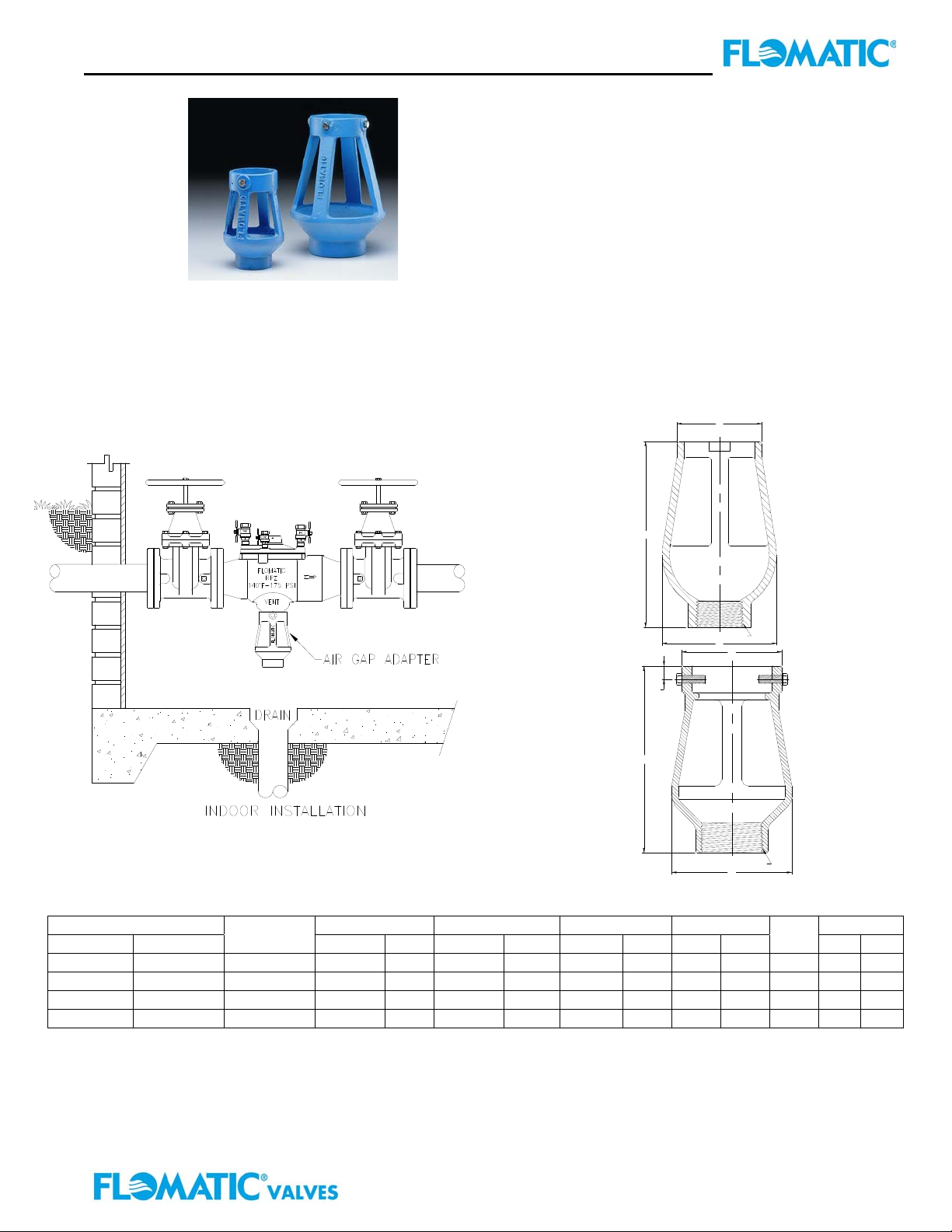
Model AGA (1/2” thru 10”)
FEATURES:
Sizes: □½” – ¾” □¾” – 2” □2½” – 3”
□4” – 10”
STANDARDS COMPLIANCE:
Size ØA B ØC D Weight
inch mm
Part #
inch mm inch mm inch mm inch mm
● ANSI/ASME A112.1.2
MATERIALS:
Body Cast Iron ASTM A126 Class B
NSF Approved Epoxy Coating
Fastners Stainless Steel, 300 series
APPLICATION:
The Flomatic model AGA is designed for use with ½”
thru 10” models RPZ, RPZE, RPZE II and RPDA
TYPICAL INSTALLATION
Local codes shall govern installation requirements. To
be installed in accordance with the manufacturers
instructions.
B
D
B
½” - ¾ 15 - 20 8473599 2-9/16 70 3-5/8 92 1-3/4 44 n/a n/a 1” .8 .36
¾” – 2” 20 - 50 8473500 3-11/64 81 5-1/8 130 2-3/8 60 n/a n/a 1” 1 .45
2½” & 3” 65 & 80 84735 4-1/2 114 7 178 3-1/2 89 ½ 13 2” 4 2
4” – 10” 100 - 250 84737 7-1/2 191 10-1/2 267 4-9/32 109 ½ 13 3” 15 7
WARRANTY: Flomatic valves are guaranteed against defects of materials or workmanship when used for the services
recommended. If in any recommended service, a defect develops due to material or workmanship, and the device is returned,
freight prepaid, to Flomatic Corporation within 12 months from the date of purchase, it will be repaired or replaced free of charge.
Flomatic Corporations’ liability shall be limited to our agreement to repair or replace the valve only.
FlomaticCorporation
C
E (NPT)
A
C
E (NPT)
A
E
NPT
lbs kg
Flomatic Corporation, 15 Pruyn’s Island, Glens Falls, New York 12801
Phone: 518-761-9797 Fax: 518-761-9798 www.flomatic.com
November 30,2004 Rev. 3 (6/11)
Specification Sheet AGA
 Loading...