

FloCat C-LB45A-MIL Operating Manual
C-LB45-A FUEL METER ASSEMBLY
INSTALLATION & OPERATION MANUAL
Version 1.4
35 GREEN MOUNTAIN DR S. BURLINGTON VERMONT 05403 USA

CONTENTS
1. Index of Figures ………………..………………………………………………….. 2
2. Notes, Warnings & Cautions ……………………………………………………... 3
3. Introduction …………………………………………………………………………. 6
4. Operating Principle of Meter ……………………………………………………… 8
5. Preparation for Use and Installation of Meter …………………………………... 8
6. Installation Instructions for Meter ………………………………………………… 9
7. Operational Start Up: Turbine Flow Meter ………………………………………. 10
8. Meter Specifications ………………………………………………………............ 13
A. Materials of Construction ……………………………………………………. 13
B. Operating Limitations ………………………………………………………… 14
9. Maintenance and Repair of Meter ……………………………………………….. 15
A. Disassembly …………………………………………………………………... 16
B. Installation of the New Kit …………………………………………………… 16
10. Introduction of Monitor ……………………………………………………............ 17
11. Specifications for Monitor …………………………………………………………. 19
12. Operating the Monitor ……………………………………………………………... 20
A. Advanced Programming Mode ……………………………………………… 20
B. Programming Using Pulse Output Turbine Flow Meters ………………… 21
13. Battery Replacement ……………………………………………………………… 26
14. Monitor Enclosure Installation ……………………………………………………. 27
A. Installation …………………………………………………………………….. 27
B. Maintenance ………………………………………………………………….. 28
15. Programming Menu Diagram …………………………………………………….. 29
16. Troubleshooting the Monitor ……………………………………………………… 30
17. General Notes on Scaling ………………………………………………………… 31
Appendix A: Troubleshooting Guide …………………………………………………… 33
Appendix B: Replacement Parts ……………………………………………………….. 34
Appendix C: Temperature Compensation Tables ……………………………………. 37
Appendix D: Meter Kit Diagrams ……………………………………………………….. 42
VERSION 1.4
1

1. INDEX OF FIGURES
Fig. 1 Photograph of main meter assembly ……………………………………… 6
Fig. 2 Photograph of comparative pipe sizes …………………………………….. 7
Fig. 3 Schematic illustration of electric signal generated by rotor movement … 8
Fig. 4 Meter installation utilizing a bypass line …………………………………… 10
Fig. 5 Meter installation without utilizing a bypass line ………………………….. 11
Fig. 6 Location of reset button ……………………………………………………... 12
Fig. 7 Typical cross-section of turbine flow meter ……………………………….. 13
Fig. 8 Typical turbine flow meter components …………………………………… 15
Fig. 9 Flow meter display …………………………………………………………… 18
Fig. 10 Front panel ……………………………………………………………………. 20
Fig. 11 Explosion proof circuit board layout (battery powered) ………………….. 25
Fig. 12 Explosion proof enclosure …………………………………………………... 26
Fig. 13 Programming menu …………………………………………………………. 29
Fig. 14 Typical turbine meter components …………………………………………. 34
Fig. 15 Kit, fuel pumping 2” ………………………………………………………….. 42
Fig. 16 Kit, fuel pumping 4” ………………………………………………………….. 43
Fig. 17 Kit, fuel pumping 6” ………………………………………………………….. 44
Fig. 18 Monitor ………………………………………………………………………… 45
Fig. 19 Monitor, cover removed ……………………………………………………... 46
VERSION 1.4
2

2. NOTES, WARNINGS & CAUTIONS:
Notes, Warnings and Cautions that appear in this manual call special attention to instructions that affect
the safe installation, function, and use of this product. Any use of this product in a manner not specified
by the manufacturer may be dangerous and will void the manufacturer’s warranty. Whenever these notes
appear please refer to accompanying documentation.
NOTE:
1. During transportation the displayed totalization may be affected. Displayed total should
be written down if you wish to keep this data. The meter should then be reset upon
arrival at its destination. Pages 8,9
2. All control valves must be located downstream of the flow meter. This is true with any
restriction in the flow line that may cause the liquid to flash. If necessary, air eliminators
should be installed to ensure that the meter is not incorrectly measuring entrained air or
gas. Page 9
3. The covers of these meters should not be removed except by authorized personnel.
The programming for this meter should not be changed except by authorized personnel.
Reprogramming the unit can affect the accuracy. Page 11
4. It may be necessary to use the temperature compensation tables in Appendix C to
maintain accurate flow measurements for fuels at low temperatures. Page 11
5. The accuracy of the meter may be affected by high viscosity fluids. This includes diesel
fuels at low temperatures. Please refer to operating instructions for accuracy information
and Appendix C for temperature compensation tables. Page 14
6. Do not interchange repair kit components as this will void the calibration data. Page 15
7. Before reassembly, note that an arrow is cast or engraved on each component. The
arrow indicates the direction of flow. The meter must be reassembled with arrowheads
pointed in the direction of the fluid flow. Each rotor support has one of its blades
notched. This notch is to be oriented in the up position on both rotor supports. The side
of the meter with the magnetic pickup signifies the up position. This is the position that
the repair kit was calibrated, and this is the position that it is to be used in to ensure
meter accuracy. See Figure 6 for proper alignment and orientation of the repair kit.
Page 16
8. The electronics will need to be re-programmed to accept the new calibration of the repair
kit if a new kit was installed. Refer to the programming section of the manual for
instructions. Page 16
9. The meter connection size and the bore size are different. For example, many of the 1”
NPT turbines have bore sizes that range from 3/8” up 1”. Be sure to use the correct bore
size or the meter could report incorrect flows and totals. Page 20
10. If flow rate is the only measurement of interest, skip to KFAC UNT to complete the
programming process. Page 20
VERSION 1.4
3

11. Password will allow users to reset totals. Page 22
12. Entering a password in the Password screen and leaving the password blank in the RST
PSWD screen would allow for total resets (not requiring password) and restrict
programming modification. Page 23
13. When installing device be sure to check instrument dimensions to avoid interference with
clamping ring on glass lens and the cover on standard units. Page 26
WARNING:
1. Make sure that fluid flow has been shut off and pressure in the line released before
attempting to install the meter in an existing system. Page 10
2. Pressure in excess of allowable rating may cause the housing to burst and cause
serious personal injury. Page 14
3. Do not open enclosure unless the area is known to be free of hazards. Failure to make
the area safe before opening the enclosure can result in a hazardous situation with a
potential for injury. Pages 17, 25
4. Electrical power must be “OFF” before and during installation and maintenance.
Page 26
5. Always disconnect primary power source before opening enclosure for inspection or
service. Page 27
CAUTION:
1. The liquid being measured should be free of any large particles that may obstruct
rotation of the rotor. If particles are present, a mesh strainer should be installed
upstream before operation of the flow meter (See Table 1). Page 9
2. Damage can be caused by striking an empty meter with a high velocity flow stream.
Page 9
3. Do not locate the flow meter or connection cable close to electric motors, transformers,
sparking devices, high voltage lines, or place connecting cable in conduit with wires
furnishing power for such devices. These meters are being used to measure highly
flammable fluids. Ignition sources could cause these fuels to explode or burn causing
serious injury or death. In addition these devices can induce false signals in the flow
meter coil or cable, causing the meter to read inaccurately. Page 9
4. High velocity air or gas may damage the internal components of the meter. Page 10
5. The meter should not be subjected to temperatures above +140° F (60° C), or below
-40° F (-40° C) or the freezing point of the metered liquid. High temperatures will
damage the magnetic pick-up and/or the electronics while lower temperatures will limit
the rotation of the rotor and possibly damage the electronic display(s). Page 14
VERSION 1.4
4

6. Excess air pressure may damage the rotor and bearings by causing the rotor to spin too
quickly. Page 16
7. All unused conduit openings must be plugged. Plugs must be a minimum of 1/8” thick
and engage a minimum of 5 full threads. Page 26
8. Use care to prevent dirt, grit or other foreign material from lodging on threads. If any
such material settles on these threads, clean them with Kerosene or Stoddard solvent,
then re-lubricate with thread lubricant. Page 26
9. Always reassemble rotor supports, rotor, and meter body with flow arrows pointing in the
same direction. Page 33
VERSION 1.4
5
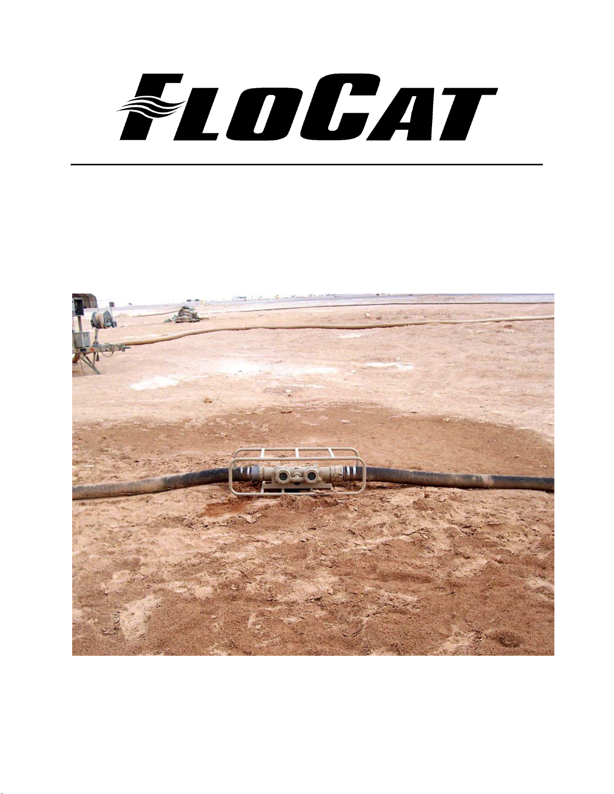
The Model C-LB45-A turbine flow meter is designed to withstand the rigorous demands of the
most remote flow measurement applications. The Model C-LB45-A flow meter maintains
measurement accuracy and mechanical integrity in a military expeditionary environment from
the Arctic to the desert or tropical regions of the world. This flow meter has been fitted with a
protective roll cage and cam lock fittings for service as a tactical fuels flow meter with ±0.5%
volumetric accuracy. This meter is intended for use with Jet A, Jet A1, JP 5, JP8, DF1, DF2, and
DF4.
The tactical fuels flow meter comes in three sizes for use with 2”, 4” and 6” fuel lines.
Fig.1 Photograph of main meter assembly
VERSION 1.4
6
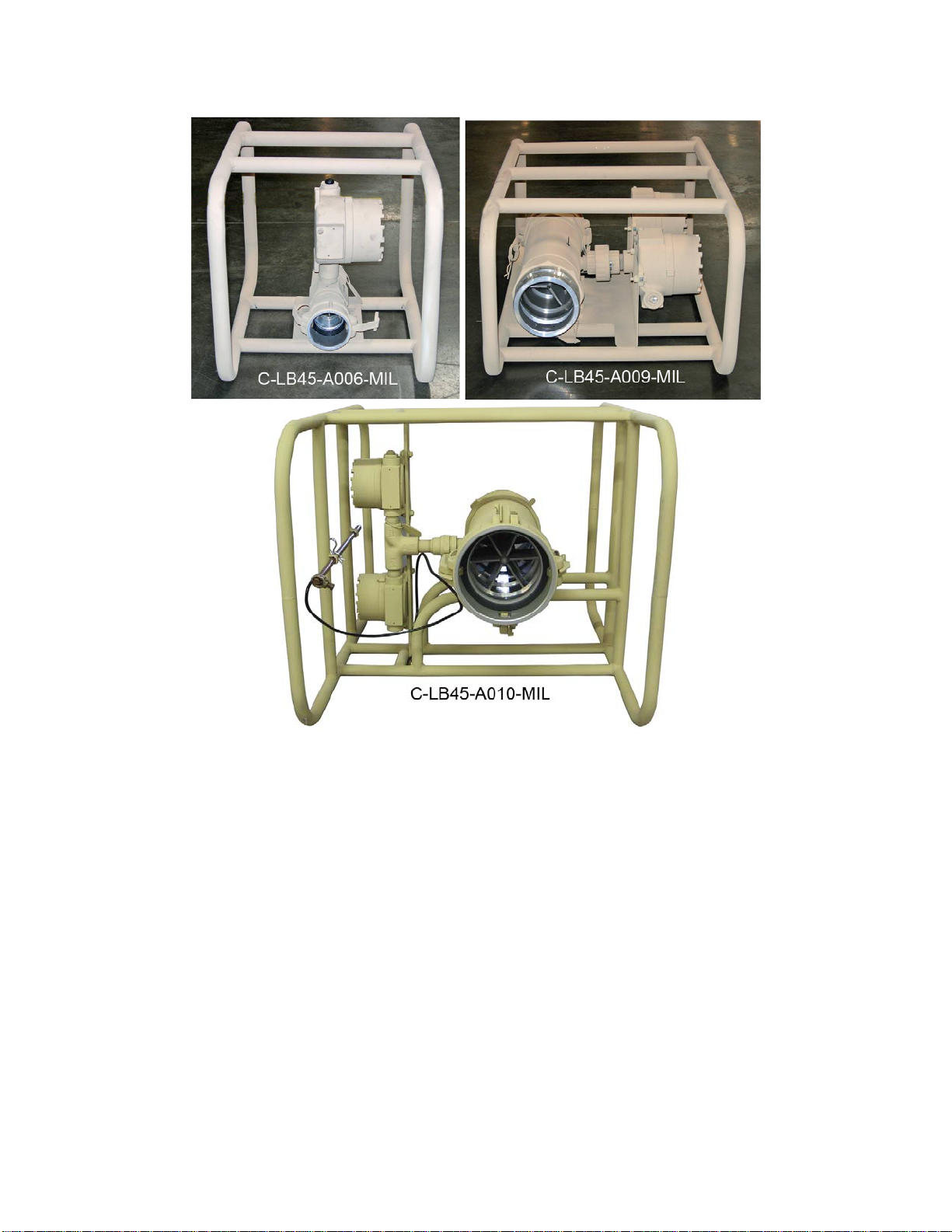
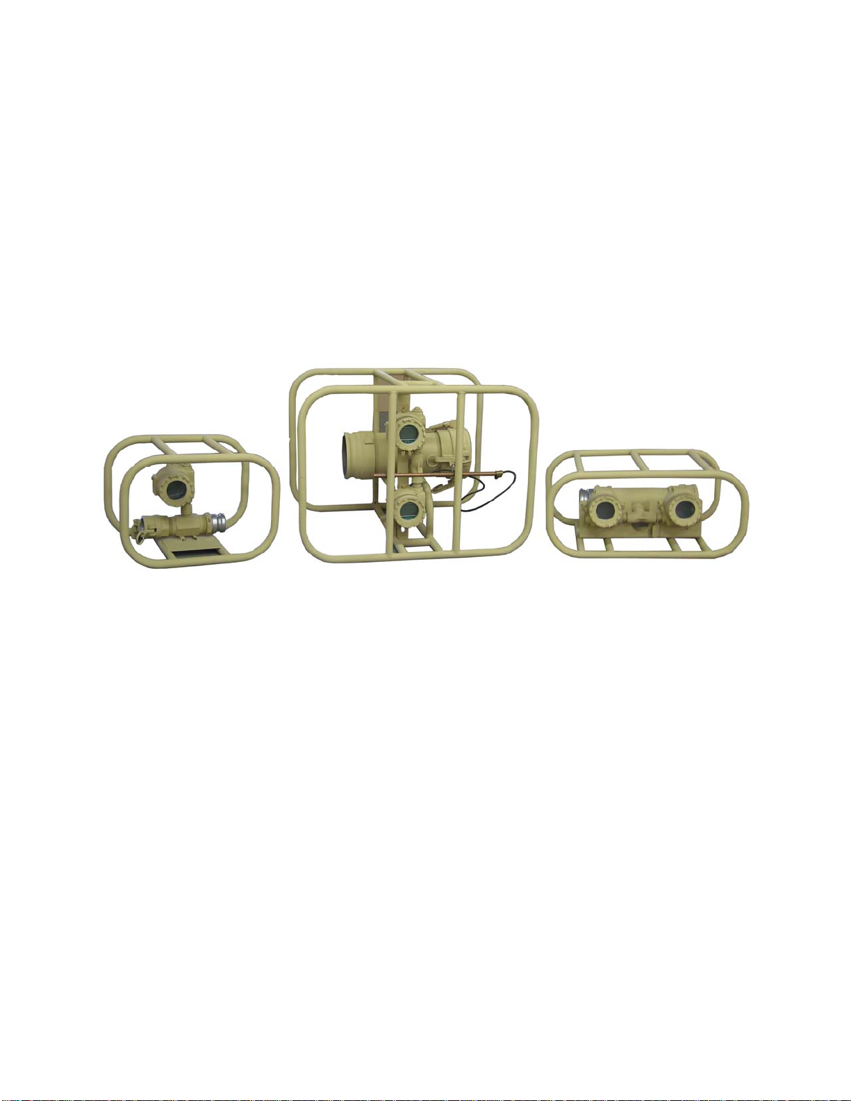
Fig. 2 Photograph of comparative pipe sizes
C-LB45-A006-MIL (2” cam lock fittings for 5 to 250 GPM) This unit weighs 19 pounds and is
20x14x14 inches (LxWxH). This unit is equipped with a single display and a reset key.
C-LB45-A009-MIL (4” cam lock fittings for 50 to 900 GPM) This unit weighs 43 pounds and is
26.5x17x12 inches (LxWxH). This unit is equipped with a dual display and a single reset key
(one display cannot be reset).
C-LB45-A010-MIL (6” cam lock fittings for 50 to 900 GPM) This unit weighs 73 pounds and is
23x26.5x31.5 inches (LxWxH). This unit is equipped with a dual display and a single reset key
(one display cannot be reset).
The tactical fuels flow meter is powered by a single “D” cell Lithium battery. A standard alkaline
battery can be used to power the meter as long as the battery is kept above minus twenty two
degrees Farenheit (-22°F). This is for temporary use only as an alkaline battery will last only a
few months depending on environmental conditions.
VERSION 1.4
7
Only four tools are required to service the C-LB45-A: a small Phillips head screwdriver, a small
flat blade screwdriver, a pair of pliers, and a 7/16” wrench.
As the tactical fuels flow meter was designed to be field transportable, it requires very little in
the way of packaging. A roll cage protects the unit from most damage that could occur from
being dropped. It is important to protect the electronic monitor(s) from being impacted from
either the top or the sides.
NOTE: During transportation the displayed totalization may be affected. Displayed total
should be written down if you wish to keep this data. The meter should then be reset
upon arrival at its destination.
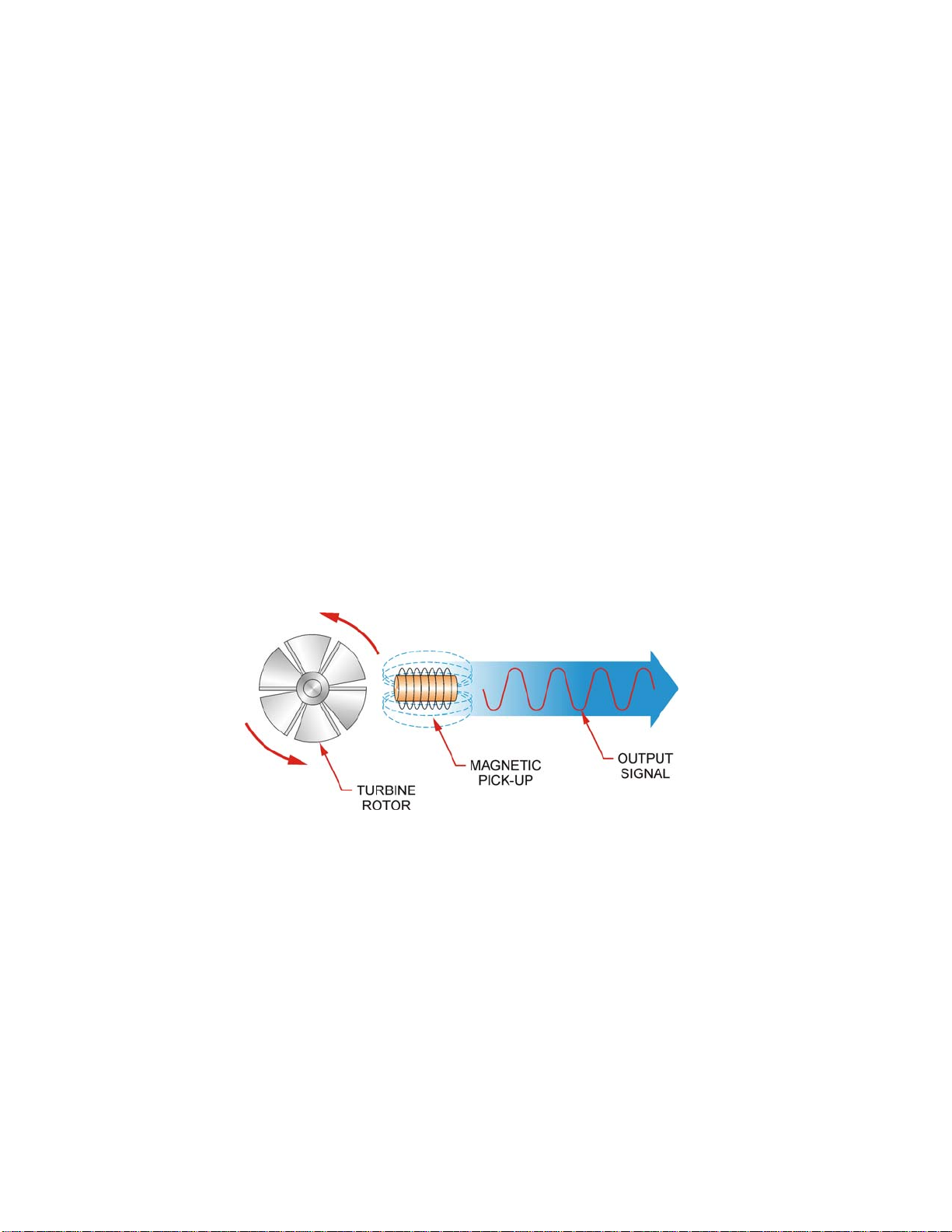
4. OPERATING PRINCIPLE OF METER:
Fluid entering the meter passes through the inlet flow straightener which reduces its turbulent
flow pattern and improves the fluid’s velocity profile. Fluid then passes through the turbine
blades causing them to rotate at a speed proportional to the fluid velocity. As each blade
passes through the magnetic field created at the base of the pickoff transducer, AC voltage
(pulse) is generated in the pickup coil (see Figure 3). These impulses produce an output
frequency proportional to the volumetric flow through the meter. The output frequency is then
used to indicate flow rate and/or totalization of fluid passing through the turbine flow meter on
the display(s).
Fig. 3 Schematic illustration of electric signal generated by rotor movement.
5. PREPARATION FOR USE AND INSTALLATION OF METER:
The C-LB45-A series flow meter is not equipped with an “on/off” button. This meter is always on
as long as the battery is installed. If the unit has been in storage and the display(s) are not
working, please check the battery. A visual check of the meter is all that is required to verify if
there has been any shipping damage. Prior to installation, the flow meter should be checked
internally for foreign material and to ensure the turbine rotor spins freely. Fuel hoses should
also be checked and cleared of all debris before being attached to flow meter.
VERSION 1.4
8

NOTE: During transportation the displayed totalization may be affected. Displayed total
should be written down if you wish to keep this data. The meter should then be reset
upon arrival at its destination.
CAUTION: The liquid being measured should be free of any large particles that may
obstruct rotation of the rotor. If particles are present, a mesh strainer should be installed
upstream before operation of the flow meter. (See Table 1)
TABLE 1
PART NUMBER STRAINER MESH CLEARANCE FILTER SIZE
C-LB45-A006-MIL 20 X 20 .0340 .86mm
C-LB45-A009-MIL 10 X 10 .0650 1.6mm
C-LB45-A010-MIL 4 X 4 .1875 4.8mm
6. INSTALLATION INSTRUCTIONS FOR METER:
The flow meter must be installed with the female cam lock on the upstream side of the fluid flow.
Though the meter is designed to function in any position, it is recommended, where possible, to
install horizontally (as shown on front cover).
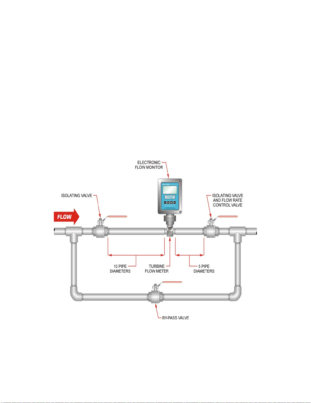
NOTE: All control valves must be located downstream of the flow meter. This is true with
any restriction in the flow line that may cause the liquid to flash. If necessary, air
eliminators should be installed to ensure that the meter is not incorrectly measuring
entrained air or gas.
CAUTION: Damage can be caused by striking an empty meter with a high velocity flow
stream.
It is recommended that a minimum length of straight hose, equal to ten (10) hose diameters of
straight hose, be installed on the up-stream (female cam lock) side and five (5) diameters on the
downstream (male cam lock) side of the flow meter. Otherwise meter accuracy may be
affected. Piping should be the same size as the meter bore or threaded port size. Use of
reducing or expansion couplers, tees, and wyes is not recommended due to the possibility of
decreased accuracy.
CAUTION: Do not locate the flow meter or connection cable close to electric motors,
transformers, sparking devices, high voltage lines, or place connecting cable in conduit
with wires furnishing power for such devices. These meters are being used to measure
highly flammable fluids. Ignition sources could cause these fuels to explode or burn
causing serious injury or death. In addition these devices can induce false signals in the
flow meter coil or cable, causing the meter to read inaccurately.
VERSION 1.4
9
7. OPERATIONAL START UP: TURBINE FLOW METER
The following steps should be followed when installing and starting the meter.
WARNING: Make sure that fluid flow has been shut off and pressure in the line released
before attempting to install the meter in an existing system.
CAUTION: High velocity air or gas may damage the internal components of the meter.
1. Open upstream isolating valve slowly to eliminate hydraulic shock while charging the meter
with the liquid. Open the valve to full open.
2. Open downstream isolating valve to permit meter to operate.
3. Adjust the downstream valve to provide the required flow rate through the meter. Note: The
downstream valve may be used as a control valve. (see figs. 4 & 5)
Fig. 4 Meter installation utilizing a bypass line
VERSION 1.4
10
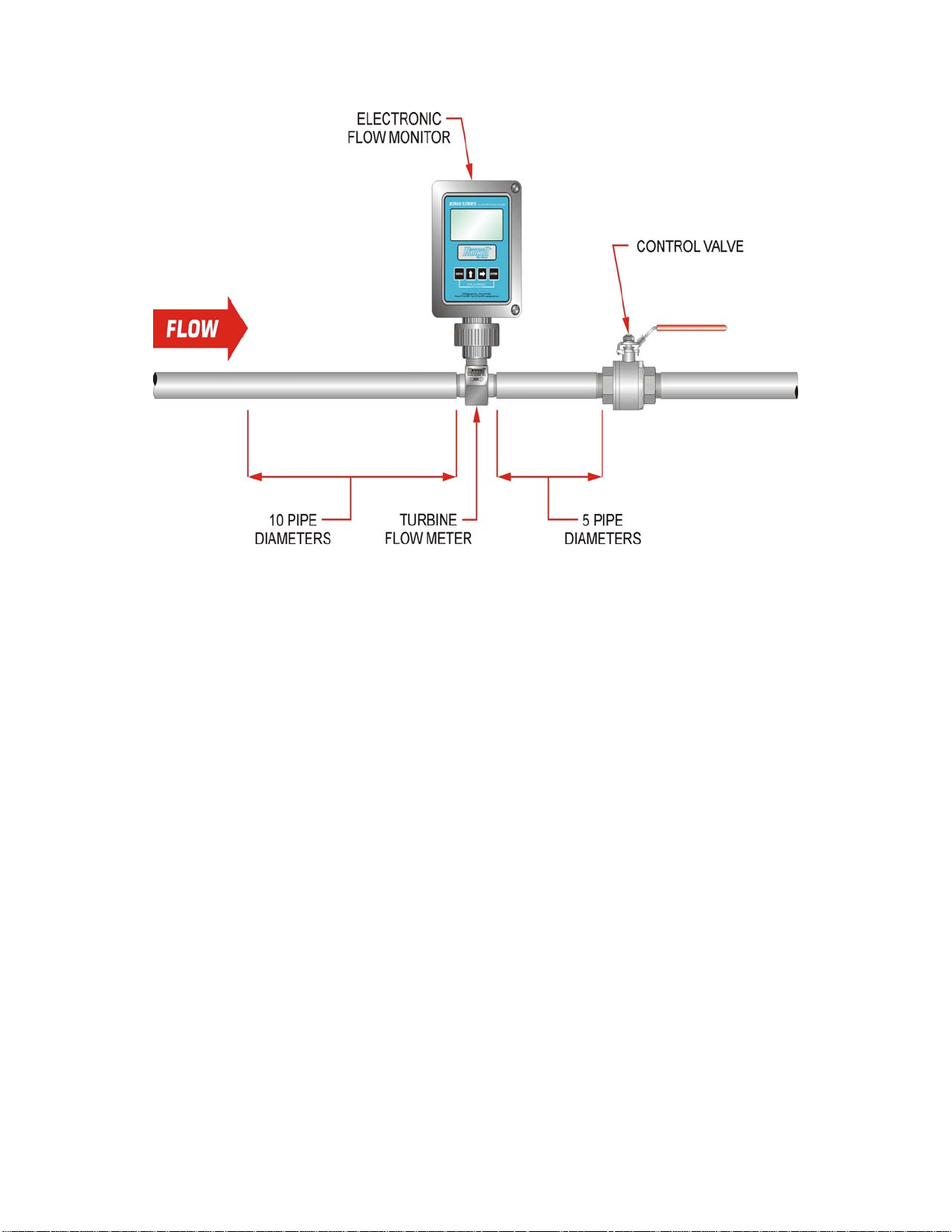
Fig. 5 Meter installation without utilizing a bypass line
These flow meters include a reset button to reset the total displayed on the monitor. The fourand six-inch models include an additional monitor that is not normally reset. This monitor is
designed to keep track of the total fuel usage. Please refer to transportation notes for important
information regarding the totalized value. To reset the totalized display of the flow meter press
the reset button. (see fig. 6)
NOTE: The covers of these meters should not be removed except by authorized
personnel. The programming for this meter should not be changed except by authorized
personnel. Reprogramming the unit can affect the accuracy.
NOTE: It may be necessary to use the temperature compensation tables in Appendix C to
maintain accurate flow measurements for fuels at low temperatures.
VERSION 1.4
11
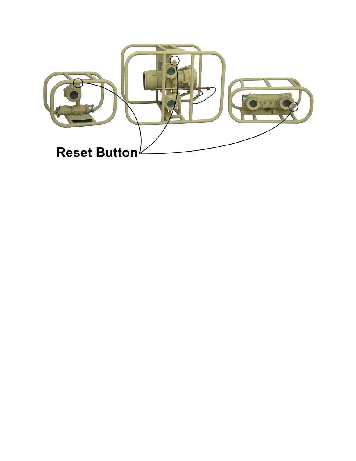
Fig. 6 Location of reset button
VERSION 1.4
12

8. METER SPECIFICATIONS:
A. MATERIALS of CONSTRUCTION:
Body: 316 Stainless Steel
Rotor: CD4MCU Stainless Steel
Rotor Support and Bearings: 316 Stainless Steel
Rotor Shaft: Tungsten Carbide
Roll Cage: Carbon Steel
Display: Aluminum and Glass
Cam Locks: Aluminum with Buna-N seals
Fig. 7 Typical cross-section of turbine flow meter.
VERSION 1.4
13

B. OPERATING LIMITATIONS:
Temperature: -40 F to +140 F (-40° C to +60° C)
CAUTION: The meter should not be subjected to temperatures above
+140° F (60° C), or below -40° F (-40° C) or the freezing point of the
metered liquid. High temperatures will damage the magnetic pick-up
and/or the electronics while lower temperatures will limit the rotation of
the rotor and possibly damage the electronic display(s).
NOTE: The accuracy of the meter may be affected by high viscosity
fluids. This includes diesel fuels at low temperatures. Please refer to
operating instructions for accuracy information and Appendix C for
temperature compensation tables.
Pressure: The following meters have a maximum operating pressure rating of:
C-LB45-A006-MIL 150 psi
C-LB45-A009-MIL 150 psi
C-LB45-A010-MIL 150 psi
WARNING: Pressure in excess of allowable rating may cause the
housing to burst and cause serious personal injury.
Accuracy: +/- 0.5% of reading.
NOTE: The accuracy of the meter may be affected by high viscosity
fluids. This includes diesel fuels at low temperatures. Please refer to
operating instructions for accuracy information and Appendix C for
temperature compensation tables.
Calibration: Water (NIST Traceable Calibration)
Corrosion: All FloCat C-LB45-A turbine meters are constructed of stainless steel and
tungsten carbide. This meter is approved for use with water and all
commercial and military aviation turbine fuels and diesel petroleum. The
operator must ensure that the operating fluid is compatible with these
materials. Incompatible fluids can cause deterioration of internal components
and cause a reduction in meter accuracy.
Pulsation and
Vibration: Severe pulsation and mechanical vibration will affect accuracy, and shorten
the life of the meter.
be installed upstream of the meter (see Table 1 for filtration recomendations).
Abrasive particles will shorten the life of the meter.
VERSION 1.4
14
 Loading...