

Page 1
Flow meters, applications assistance and technical support
C-SF45-A Series
Instruction Manual
P.N. C-SF99-B001
35 Green Mountain Dr
South Burlington, VT 05403
Page 2

DESCRIPTION:
C-SF45-A series turbine f ow sensors measures the f ow of hydrocarbon fuels such as gasoline, kerosene, #2 diesel fuel, and other light transmitting, non-corrosive liquids of similar viscosity. Typical fuel f ow applications include aircraft fuel monitoring systems; gasoline, diesel,
and gas turbine engine test stands; and industrial furnaces.
The transducers give repeatable signals on gasoline across a 100 to 1 f ow range down to 0.3
GPH. The higher viscosity of diesel fuel reduces signal repeatability at f ow rates below 2 GPH.
Pressure drops are very low compared to other turbine f ow sensors. The sensor’s bearing
system is rated for continuous operation at the upper end of the f ow range.
The sensor produces a current pulse signal from an opto-electronic pickup with a preamplif er.
PRINCIPAL OF OPERATION
Liquid enters the f ow chamber tangentially, follows a helical f ow path, and exits vertically,
thereby venting any entrained vapor bubbles. The rotational velocity of the liquid is directly proportional to f ow rate. A neutrally buoyant rotor spins with the liquid between V-jewel bearings.
Rotor movement is sensed when notches in the rotor interrupt an infrared light beam between
an LED and phototransistor.
The vapor venting design requires that the transducer be positioned with the wires pointing
up. Turbulence caused by valves or sharp elbows mounted close to the transducer inlet can
affect the sensor’s K-Factor and should be minimized.
PERFORMANCE SPECIFICATIONS
Model Number C-SF45-A001 C-SF45-A002 C-SF45-A003
Flow Range,
Gasoline 0.3 - 30 GPH 0.6 - 60 GPH 2.0 - 80 GPH
#2 Diesel 2.0 - 30 GPH 3.0 - 60 GPH 8.0 - 80 GPH
Approximate K Factor
(Pulses/Gallon @ 16 GPH)
Gasoline 32,000 28,000 - 31,000 24,000
#2 Diesel 33,000 28,000 25,000
Pressure Drop
Gasoline 0.6 psi @ 15 GPH 1.2 psi @ 30 GPH 1.4 psi @ 40 GPH
2.4 psi @ 30 GPH 4.8 psi @ 60 GPH 5.8 psi @ 80 GPH
#2 Diesel 0.8 psi @ 15 GPH 1.5 psi @ 30 GPH 1.8 psi @ 40 GPH
3.0 psi @ 30 GPH 6.0 psi @ 60 GPH 7.2 psi @ 80 GPH
Repeatability ±0.5% @ 16 G ±0.5% @ 16 ±0.5% @ 16 GPH
Working Pressure 200 psi 200 psi 200 psi
Temperature Range -65° / 100°C -65° / 100°C -65° / 100°C
Bearing Life Expectancy 10,000 hr. min. 10,000 hr. min. 10,000 hr. min.
Page 1
Page 3

C-SF45-A SERIES FLOW SENSOR INSTALLATION
Sensors must be placed in a horizontal section of fuel line at a low point in the fuel system.
Fuel should travel, “Up-hill” when exiting the sensor. Its outlet should be at least 1 or 2 inches
lower than the fuel pump inlet, or priming bulb. Placing the sensor at least 12” upstream of the
fuel pump improves system accuracy.
To prevent the sensor from clogging, it is recommended that the sensor(s) be installed downstream of a coarse fuel f lter or water separator. For applications not equipped with an off
engine f lter we suggest installing a model ILA-02 Flow Ezy f lter w/238 micron screen directly
to the inlet of the f ow sensor.
Caution: Never Plumb Flow Sensor(s) Downstream of an Engine Mounted Fuel Filter.
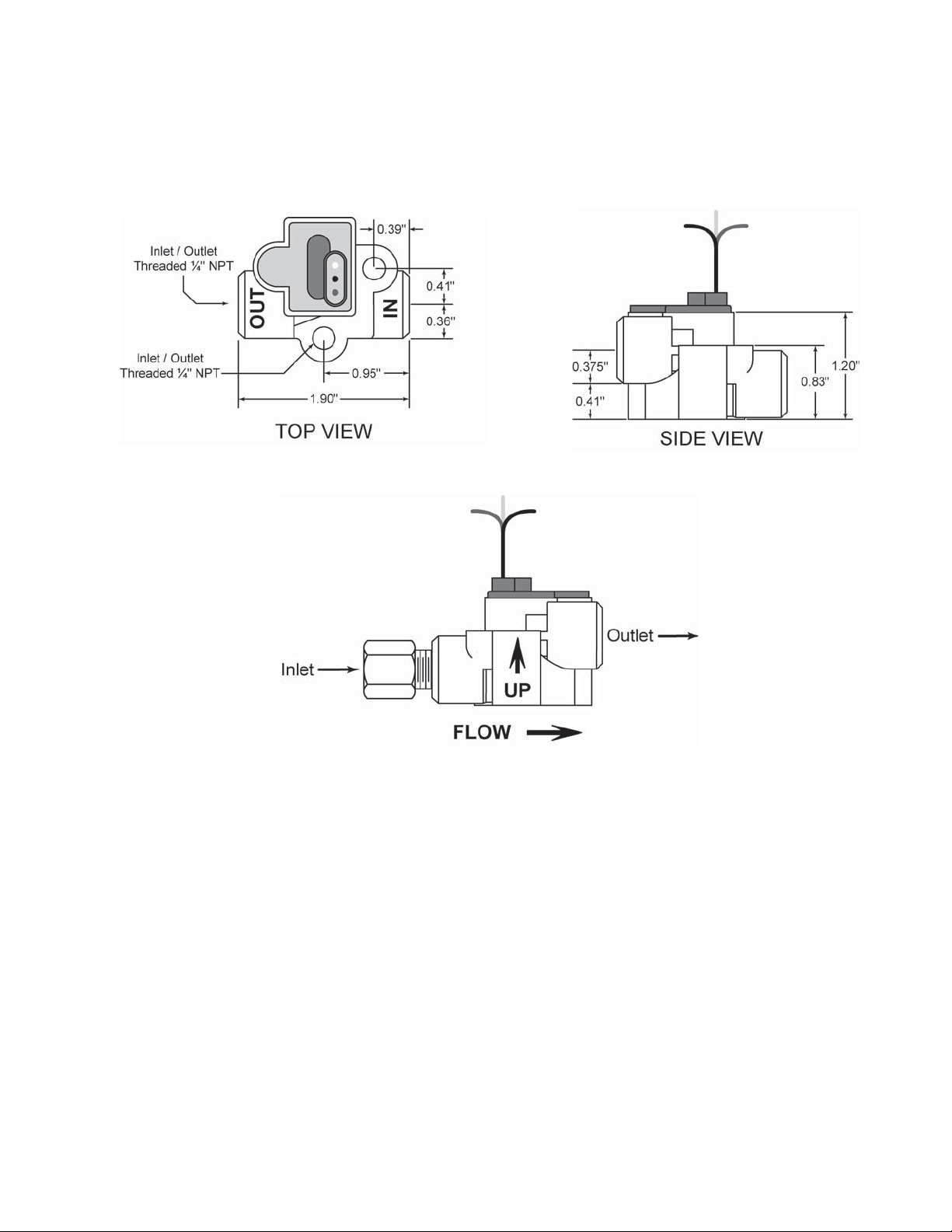
The sensors ports are marked with IN and OUT. They must be installed with the proper orientation and with the wires up.
Minimize the number of 90º elbows and pipe f ttings. Excessive use may create a high vacuum, fuel restricting pressure drop across the fuel system. Whenever possible, use a large radius hose bend instead of elbows. Refer to the engine owner’s manual for maximum fuel pump
vacuum. A vacuum gauge can be used to conf rm that the system is within limits.
DO NOT OVER TIGHTEN FITTINGS. Torque pipe thread f ttings to a maximum of 15 ft-LB,
(180 inch-Lb) or two full turns beyond hand tight, (Whichever comes f rst). FloCat recommends
that a fuel proof pipe thread sealant be used when installing f ttings into the f ow sensors,
(LockTite PST, Rector Seal, Leaklok, Permatex, Jomar, etc). NEVER USE TEFLON TAPE.
If swivel f ttings are used, (JIC or SAE) their mating surfaces should be sealed with AP 50 Fitting Seals, or Copper Conical Sealing Washer, (Connie Seals)
MATERIAL SPECIFICATIONS:
Flow Sensor Body Die-cast Aluminum, Cadmium Plated, Dichromate Finish
Rotor Nylon 6/12
Rotor Pivot Stainless Steel, Carpenter 420
Phototransistor SD 1440
Light Emitting Diode SE 1450
Connectors 22 Gauge Wire Leads (3)
ELECTRICAL SPECIFICATIONS:
12 to 15 VDC between RED (+) wire and BLACK (-) wire. 30 to 50 mA at 12 VDC.
Page 2
Page 4
SIGNAL SPECIFICATIONS:
Open collector transistor output on WHITE wire. Sensor will pull-down to 1.0 volt with 10 - 15k
ohm pull-up resistor installed.
DIMENSIONS
TEST THE FLOW SENSORS.
At the readout, disconnect the RED (switched +12 VDC) wire from the switched source and
temporarily connect it to an un-switched source so the instrument is powered even when the
engine is OFF. All other wires are as per the wiring diagram.
FINDING SUCTION LEAKS IN FUEL SYSTEMS
By far, the most common complaint received is FLUCTUATING GPH READINGS or HIGH
READINGS caused by a suction leak somewhere between the fuel tank and the inlet of the
fuel pump. The symptom of a suction leak shows up on the GPH reading as a f uctuation. The
more severe the leak, the greater the f uctuation will be. Typically, the f uctuation is around 2
- 4 GPH. This also affects the totalizer reading and usually shows a 15 - 30% higher reading
than what you’ve put into the tank. Suction leaks occur with both gasoline and diesel engines
and will not affect engine performance except in severe cases.
Page 3
Page 5

If you have f uctuating readings, but the totalizer reading is close to what you’ve put into the
tank (+/- 6%), something is causing the fuel to f ow through the system that way. The most
likely causes are an anti-siphon valve set too stiff or a sticky or misadjusted f oat valve on the
gasoline engine’s carburetor. Repair or replace as needed.
Finding suction leaks can be a tedious and time-consuming chore, but properly approached, it
can be repaired in a minimum amount of time. The two most common places for suction leaks
to occur are at the primary fuel f lter/water separator and/or from a loose valve stem packing
gland nut.
First, remove the f lter housing. Coat any o-rings or gaskets you f nd with a coating of light
grease (not machine oil or diesel oil) and reassemble. Gently tighten all valve stem packing
gland nuts. Do not over tighten, valve should turn freely. Tighten all hose clamps and compression f ttings (do not over tighten). Run the engine for 5 - 10 minutes and observe readings. If
you’ve found the problem, the f uctuations should reduce to less than ½ GPH of the reading.
If this does not cure the problem, the next step is to temporarily insert a clear piece of fuel
resistant tubing. For gasoline engines, install it to the inlet of the fuel pump. For diesel engines,
install it after the return f ow sensor. Run the engine and watch the clear tubing for signs of a
constant stream of small bubbles or an occasional larger bubble. Sometimes shining a light
through the clear tube makes it easier to see.
Have someone observe the clear tube while you move any f exible hose(s) in the fuel system.
If the amount of bubbles observed continually increase or decreases as you do this, you have
found the area causing the leak. Repair or replace as needed. If it is a one time occurrence,
you probably dislodged some air trapped in the fuel line.
If you haven’t found it yet, the last step is to inspect each pipe joint in the system. You should
be able to see joint compound all the way around the joint. If you do not, that joint is suspect
and needs to be resealed. You should now see the clear tube running with solid fuel and free
of any bubbles. You may need to run the engine for a few minutes to purge any air that was
in the system. If you still see bubbles in the clear tubing, you missed the leak somewhere and
need to check back over your work. Remove the clear tube and restore the fuel system to its
normal condition.
FUEL FILTERS
A dirty fuel f lter or one that is too f ne (1-5 micron) may cause cavitation (drawing vapor out of
the fuel). Replace the f lter with a new one in the 10-20 micron range or larger, depending on
engine manufacturers recommendations.
FLOW SENSOR ORIENTATION
The importance of proper orientation of the f ow sensor can not be emphasized enough. All
f ow sensors come with the inlet and outlet distinctly marked (IN / OUT). This signif es fuel f ow
direction and is imperative for the sensor to work correctly in the system. There is an additional
arrow on the body of the f ow sensor. This will either be a label clearly marked or stamped onto
Page 4
Page 6

the body of the sensor itself. It is crucial that this single arrow points up. Please be careful to
install the sensor in the proper orientation. Before installing the sensor(s), familiarize yourself
how the sensor(s) is to be installed.
LOW RPM OPERATION
At idle, under no load conditions, it is not uncommon for the GPH reading to f uctuate by as
much as .2 -.3 GPH. This f uctuation is caused by the engine governor f uctuating the fuel f ow
to maintain engine RPM.
Page 5
 Loading...