

FloAire PCU Filtration User Manual
Pollution Control Unit
Installation, Operation, and Maintenance Manual
Pollution Control Unit
Save these instructions
RECEIVING AND INSPECTION
WARNING!!
Upon receiving unit, check for any interior and exterior damage, and if found, report it
immediately to the carrier. Also check that all accessory items are accounted for and are
damage free.
Installation of this unit should only be performed by a qualified professional who has read and
understands these instructions and is familiar with proper safety precautions. Read this
manual thoroughly before installing or servicing this equipment.
. This document is the property of the owner of this equipment and is
required for future maintenance. Leave this document with the owner when installation or
service is complete.
August 2014 Rev. 22
A0011036

2

TABLE OF CONTENTS
WARRANTY .................................................................................................................................................. 4
LISTINGS ...................................................................................................................................................... 5
APPLICATION .............................................................................................................................................. 5
INSTALLATION ............................................................................................................................................. 6
Site Preparation ........................................................................................................................................ 6
Joint Sealant ............................................................................................................................................. 6
Sealant Features ...................................................................................................................................... 6
Ductwork ................................................................................................................................................... 7
Recommended MIN Ductwork Sizes.................................................................................................... 7
Unit Drains ................................................................................................................................................ 7
Equipment Rails ........................................................................................................................................ 8
Roof Mount Installation (Typical) .............................................................................................................. 8
Indoor (Inline) Installation (Typical) .......................................................................................................... 8
Air Pressure Switch Option ....................................................................................................................... 9
Advanced Filter Pressure Monitoring Option .......................................................................................... 10
HMI MENUS ....................................................................................................................................... 11
PCUFMM Wiring ................................................................................................................................. 13
Troubleshooting .................................................................................................................................. 14
Fire System ............................................................................................................................................. 15
Climate Controlled Utility Cabinet ....................................................................................................... 15
OPERATION ............................................................................................................................................... 17
Start Up ................................................................................................................................................... 17
Special Tools Required ...................................................................................................................... 17
Start Up Procedure ............................................................................................................................. 17
Troubleshooting ...................................................................................................................................... 18
Troubleshooting Chart ........................................................................................................................ 18
MAINTENANCE .......................................................................................................................................... 19
General Maintenance ............................................................................................................................. 19
Filter Information ..................................................................................................................................... 19
Standard Filter Part Numbers ............................................................................................................. 20
Optional Pre Filter, High Efficiency, and HEPA Filter Part Numbers ................................................. 20
Optional Odor Control Media Part Numbers ...................................................................................... 20
Gasket Type Chart .................................................................................................................................. 21
2 Weeks After Startup ............................................................................................................................. 21
Every Month ............................................................................................................................................ 21
Duct Cleaning ......................................................................................................................................... 21
Yearly ...................................................................................................................................................... 21
Start-Up and Maintenance Documentation ............................................................................................ 22
Job Information ................................................................................................................................... 22
PCU Information ................................................................................................................................. 22
Advanced Filter Pressure Monitoring Information .............................................................................. 22
Maintenance Record .......................................................................................................................... 22
Factory Service Department ............................................................................................................... 22
3

WARRANTY
This equipment is warranted to be free from defects in materials and workmanship, under normal use and
service, for a period of 12 months from date of shipment. This warranty shall not apply if:
1. The equipment is not installed by a qualified installer per the MANUFACTURER’S installation
instructions shipped with the product,
2. The equipment is not installed in accordance with federal, state and local codes and regulations,
3. The equipment is misused or neglected,
4. The equipment is not operated within its published capacity,
5. The invoice is not paid within the terms of the sales agreement.
The MANUFACTURER shall not be liable for incidental and consequential losses and damages
potentially attributable to malfunctioning equipment. Should any part of the equipment prove to be
defective in material or workmanship within the 12-month warranty period, upon examination by the
MANUFACTURER, such part will be repaired or replaced by MANUFACTURER at no charge. The
BUYER shall pay all labor costs incurred in connection with such repair or replacement. Equipment shall
not be returned without MANUFACTURER’S prior authorization and all returned equipment shall be
shipped by the BUYER, freight prepaid to a destination determined by the MANUFACTURER.
4

LISTINGS
This pollution control unit (PCU) is ETL listed to standard UL-710, CAN/ULC-S646, CAN/ULC-S647 when
installed in accordance with these installation instructions and National Fire Protection Association
Standard “NFPA 96, Standard for Ventilation Control and Fire Protection of Commercial Cooking
Operations.”
APPLICATION
The listed pollution control unit is suitable for use in commercial cooking installations for the removal of
smoke and grease laden vapors.
Grease duct installations require provisions for cleaning the interior of the duct. NFPA 96 cleanout
requirements are as follows:
1. A cleanout must be provided at each change of direction except where the entire length of duct
can be inspected and cleaned from either the hood or the discharge end.
2. On horizontal duct runs, at least one (1) 20” diameter opening must be provided. Where the
opening is smaller than 20” diameter, openings large enough to permit cleaning must be provided
at intervals of no more than 12’.
3. Openings in the duct must be at the side or the top, whichever is more accessible. When the
opening is on the side of the duct, the lower edge of the opening must be at least 1 ½” above the
bottom of the duct. For listed grease duct, this is accomplished by the use of the grease manifold
tee and cleanout cap.
4. On vertical duct runs where personnel entry is possible, access must be from the top of the riser.
Where entry is not possible, access must be provided at each floor.
NOTE: ACCESS REQUIREMENTS ARE SUBJECT TO CHANGE IN ACCORDANCE WITH LOCAL
CODE. LOCAL AUTHORITIES SHOULD BE CONSULTED FOR EXACT REQUIREMENTS. GREASE
DUCT MAY BE CONNECTED ONLY TO HOODS IN A SINGLE FIRE ZONE ON ONE FLOOR. DO
NOT CONNECT GREASE DUCTS TO ANY OTHER PART OF THE BUILDING VENTILATION OR
EXHAUST SYSTEM.
A grease fire can burn at extremely high temperatures. This system should be dismantled and inspected
after any exposure to a grease fire. Any section that is distorted or discolored should be replaced. All
joints in the system should be examined. Because the sealant expands to assure a positive seal in the
case of a fire, any sealant that has been exposed to high temperature must be replaced. This will ensure
that the system maintains its integrity against fire conditions in the future. The manufacturer of this PCU
cannot be responsible for grease duct systems that are not properly maintained or have been subjected
to one or more grease fires. Warranty and listing is void in a fire situation without consulting factory.
Grease duct systems size and capacity information may be obtained from the “ASHRAE Handbook –
Fundamentals” or from the “Air Pollution Engineering Manual” of the “US Environmental Protection
Agency.” Refer to the grease duct systems catalog for descriptions and dimensional data of parts.
5

INSTALLATION
It is imperative that this unit is installed and operated with the designed airflow, filters, exhaust fan
placement, and construction in accordance with this manual. If there are any questions about any items,
please call the service department at 1-866-784-6900 for warranty and technical support issues.
WARNING: DO NOT RAISE PCU BY THE DOOR, FILTER FRAMES, OR UTILITY
CABINET – USE LIFTING LUGS PROVIDED OR A SLING.
Site Preparation
1. Provide clearance around installation site to safely rig and lift equipment into its final position.
Supports must adequately support equipment. Refer to manufacturer’s estimated weights.
2. Consider general service and installation space when locating unit. Allow a minimum of 36
inches of clearance on the filter removal side of the unit to replace filters.
3. Locate unit close to the space it will serve to reduce long, twisted duct runs
4. Support unit above ground or at roof level high enough to prevent precipitation from being drawn
into unit.
5. The PCU is designed to operate in a negative pressure environment. Be sure to install the PCU
between the exhaust fan and hoods. This will also keep the fan cleaner during operation.
6. The PCU drains must be connected to the building grease interceptor or an approved building
drain. Black Iron or Stainless Steel Pipe must be used for this connection. If PCU assembly has
Multiple Modules, the drain line must be 2.5 inch NPT pipe minimum.
7. Determine if adequate room is available to install the PCU assembly and all ductwork with proper
clearance to combustible material. ETL listing for clearance to combustible surfaces to this
PCU unit is 18 in. It is important to check with the local authority having jurisdiction to determine
that the installation method is satisfactory to meet their requirements prior to installation.
Joint Sealant
The joint sealant used to seal all internal joint assemblies is a 3M product. 3M Fire Barrier 2000 +
Silicone Sealant is a ready-to-use, gun-grade, one-component silicone elastomer that cures upon
exposure to atmospheric humidity to form a flexible seal. 3M Fire Barrier 2000 + Silicone Sealant, when
installed properly, will control the spread of fire before, during and after exposure to open flames. It will
stop the spread of noxious gas, smoke and water and maintain the integrity of fire rated assemblies and
construction. NO SEALANT SUBSTITUTES MAY BE USED.
Sealant Features
1. Superior adhesion.
2. Capable of withstanding 2000 °F + temperatures.
3. Class 25 sealant, per ASTM 920.
4. Re-enterable/repairable.
5. Provides up to 4-hours fire-rating.
6. Cures upon exposure to atmospheric humidity.
7. Working time 30 minutes.
8. Cure time 14 to 21 days.
9. Applied with a standard caulk gun.
6
Ductwork
The ductwork attached to this unit will significantly
affect the airflow performance. Flexible ductwork
and square elbows should not be used. There
must be at least 3 duct diameters of straight
duct leading to the inlet and at the outlet of the
pollution control unit. The chart to the right
shows the recommended duct sizes for optimal
performance. The maximum velocity at the inlet
of the pollution control unit must be less than
1000 feet per minute for light duty applications
and less than 800 feet per minute for heavy
duty applications and solid fuel applications.
Follow SMACNA guides and recommendations for the remaining duct run.
Ensure duct connections are properly aligned and sealed. When the pollution control unit is used in
commercial grease ductwork, the ductwork connections must be FULLY WELDED to the PCU. Ductwork
must be listed or installed in accordance with the IMC. When pollution control unit is installed in grease
rated ductwork, the clearance to combustible surfaces to this pollution control unit is 18 in.
Recommended MIN Ductwork Sizes
PCU Size Duct Height Duct Width
PCU-1 23 in. 23 in.
PCU-2 30 in. 30 in.
PCU-3 35 in. 35 in.
PCU-4 43 in. 43 in.
PCU-5 50 in. 52 in.
PCU-6 46 in. 58 in.
Unit Drains
Each module of the Pollution Control Unit contains a drain that must be connected to an approved
grease interceptor or to an approved drainage point. The drain connections must be made with Black
Iron or Stainless Steel piping. This will allow the water collected in the unit, either from Self Cleaning
hood, ductwork cleaning, or from the Core Protection Fire System, to drain away from the unit. If installed
outdoors, the drains must be piped so that water cannot buildup in the pipes and burst due to freezing.
7
Equipment Rails
The unit should be installed on a curb and/or rail elevated not less than 14” above any roof surface.
Secure PCU to rails through vertical portion of the PCU base assembly flange using a minimum of eight
(8) lug screws, anchor bolts, or other suitable fasteners (not furnished). Shims may be required
depending upon equipment rail installation and roofing material. W hen installed indoors, uni-strut
channels may be used under the PCU for attachment to threaded rod from the roof structure above.
Check all fasteners for tightness. The diagrams below show different mechanical installation
configurations.
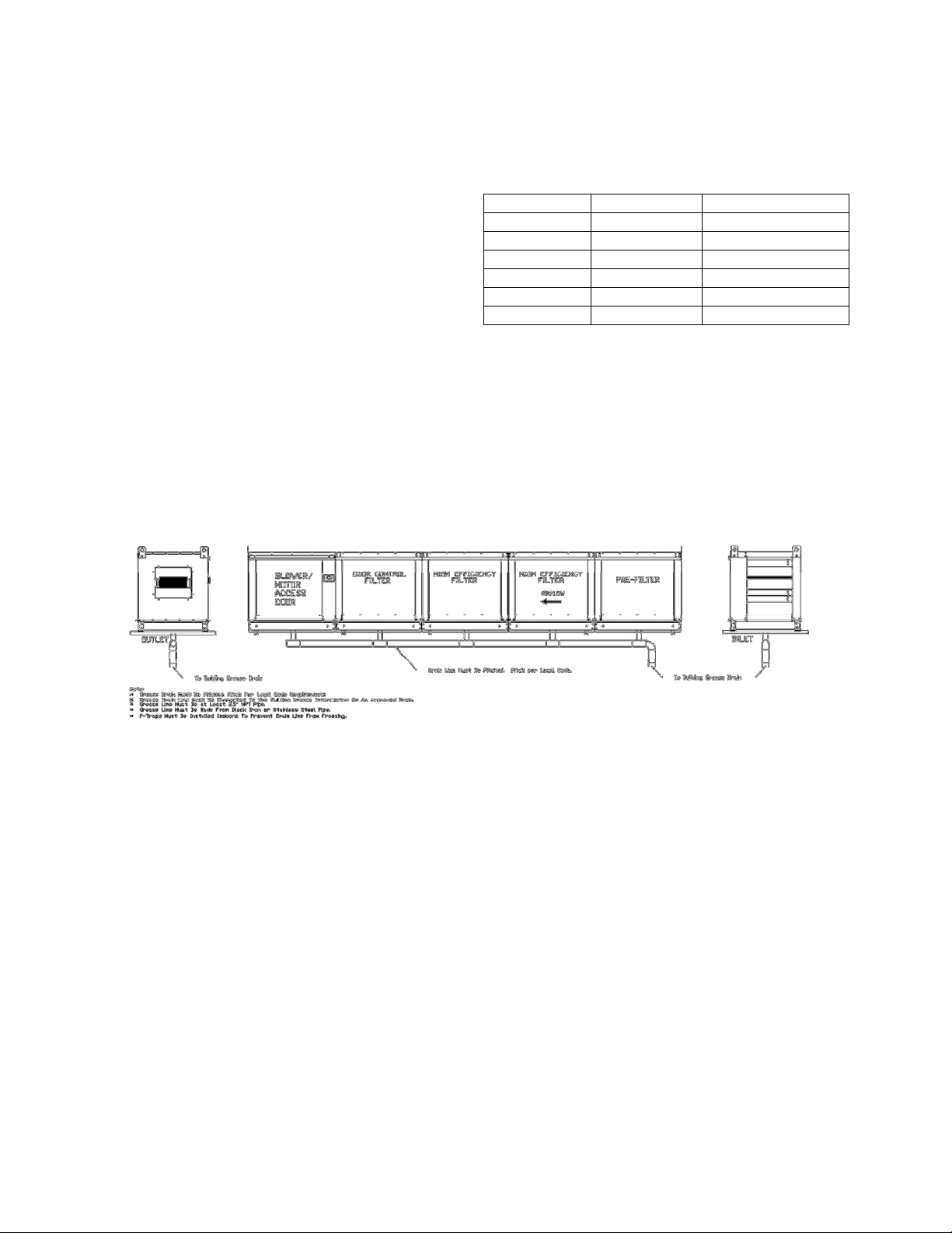
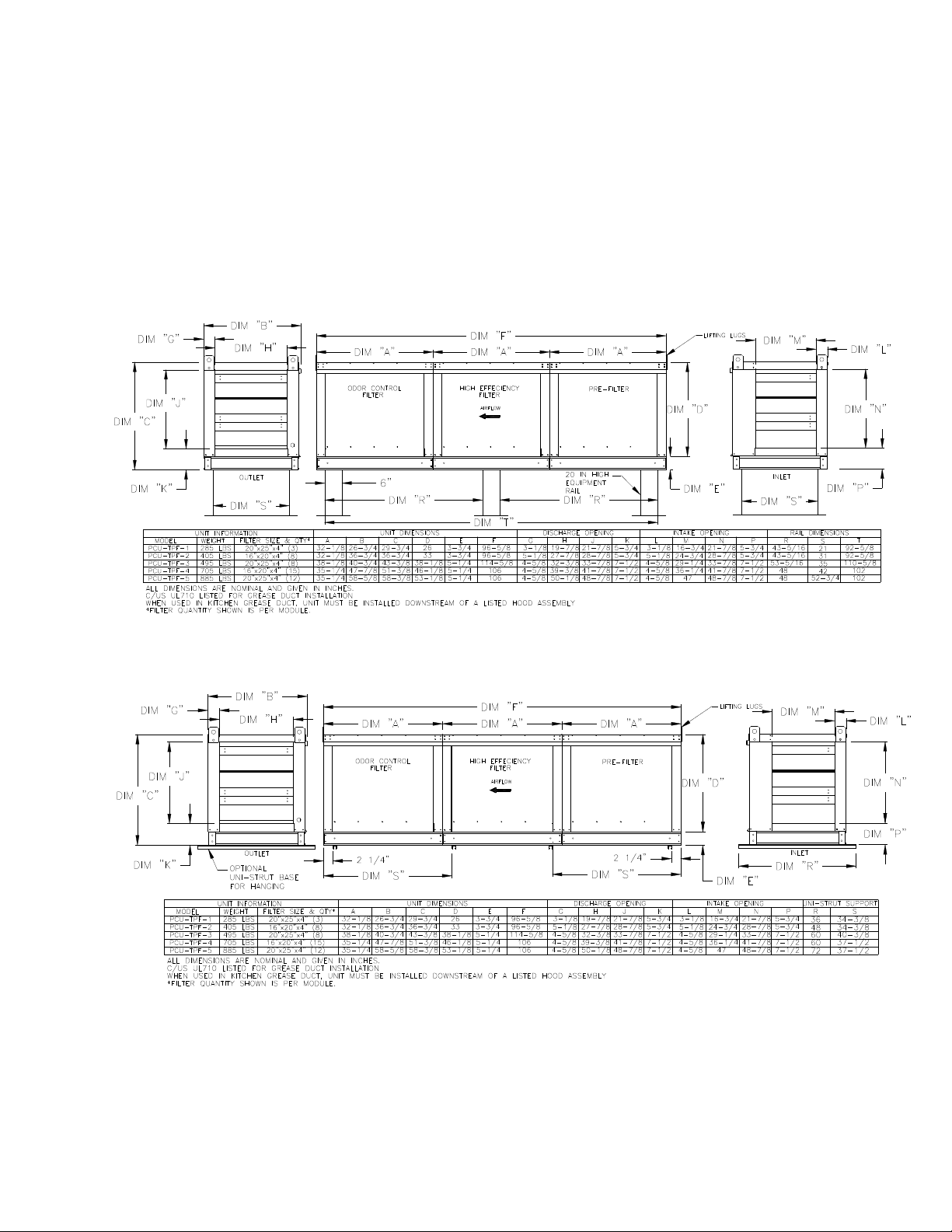
Roof Mount Installation (Typical)
Indoor (Inline) Installation (Typical)
8
 Loading...