

Page 1
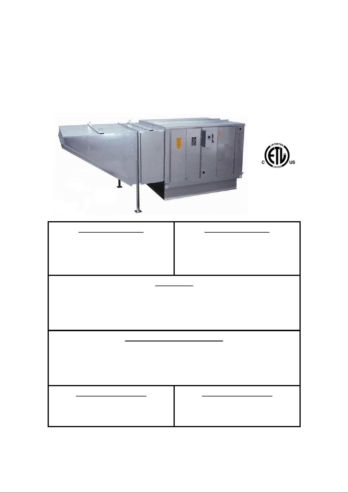
Installation & Operation
Guide
Industrial
Non
Re-circulating
Direct
-
Fired Heaters
Horizontal / Vertical and Single / Twin Blowers
.
FOR YOUR SAFETY
If You smell gas:
1. Open windows
2. Don’t touch electrical switches
3. Extinguish any open flames
4. Immediately call your gas supplier
WARNING!!
FOR YOUR SAFETY
The use and storage of gasoline or
other flammable vapors and liquids in
open containers in the vicinity of this
appliance is hazardous!
Improper installation, adjustment, alteration, service or maintenance can cause
property damage, injury or death. Read the installation, operating and
maintenance instructions thoroughly before installing or servicing this equipment
ALWAYS disconnect power and gas before working on heater.
RECEIVING AND INSPECTION
Upon receiving unit, check for any interior or exterior damage, and if found,
report it immediately to the carrier. Also check that all accessory items are
accounted for and are damage free. Turn the blower wheel by hand to verify
free rotation and check the damper (if supplied) for free operation.
NOTE TO INSTALLER
Please complete and return the
Start-UP Checklist on the back of this
manual to validate warranty
NOTE TO INSTALLER
This manual should be reviewed with
the customer and left with the
equipment user
Revision 12 – 11.19.2013
Page 2

2
Page 3

TABLE OF CONTENTS
WARRANTY ............................................................................................................................... 4
INSTALLATION ........................................................................................................................... 4
Gas ........................................................................................................................................... 11
Electrical ............................................................................................................................... 12
Gas Connection Diagram .................................................................................................. 12
Copper Wire Ampacity ...................................................................................................... 12
SEQUENCE OF OPERATIONS ................................................................................................ 13
Standard Sequence of Operation .......................................................................................... 13
Additional Sequence of Operation – All VFD Motor Control.................................................... 14
VFD Preset Speeds .............................................................................................................. 14
START-UP PROCEDURE ......................................................................................................... 15
PROFILE ADJUSTMENTS ........................................................................................................ 21
VFD Drive Installation & Programming Instructions .................................................................... 22
OTHER UNIT COMPONENTS .................................................................................................. 24
Flame Safety Control ........................................................................................................ 24
High Temperature Limit ..................................................................................................... 24
Electric Cabinet Heater ..................................................................................................... 24
DC Flame Signal ............................................................................................................... 24
TROUBLESHOOTING .............................................................................................................. 26
MAINTENANCE ........................................................................................................................ 38
Burner Orifice Drill Size .................................................................................................... 39
START-UP CHECKLIST ........................................................................................................... 40
3
Page 4

WARRANTY
This equipment is warranted to be free from defects in materials and workmanship, under normal
use and service, for a period of 12 months from date of shipment. This warranty shall not apply if:
• the equipment is not installed by a qualified installer per the manufacturer’s installation
instructions shipped with the product
• the equipment is not installed in accordance with federal, state and local codes and
regulations
• the equipment is misused or neglected
• the equipment is not operated within its published capacity
• the invoice is not paid within the terms of the sales agreement
• the Start-Up Checklist has not been filled in by a qualified technician and returned to the
Factory Service Department
The manufacturer shall not be liable for incidental and consequential losses and damages
potentially attributable to malfunctioning equipment. Should any part of the equipment prove to
be defective in material or workmanship within the 12-month warranty period, upon examination
by the manufacturer, such part will be repaired or replaced by manufacturer at no charge. The
buyer shall pay all labor costs incurred in connection with such repair or replacement. Equipment
shall not be returned without manufacturer’s prior authorization and all returned equipment shall
be shipped by the buyer, freight prepaid to a destination determined by the manufacturer.
NOTE TO INSTALLER
Please complete and return the
Start-UP Checklist on the back of this manual to validate warranty
INSTALLATION
It is imperative that this unit is installed and operated with the designed airflow, gas, and electrical
supply in accordance with this manual. Any variance to these instructions may cause the unit to not
perform to specifications and may cause severe damage to the unit or jobsite. Please call the service
department at 866-784-6900 for assistance on warranty issues and technical support.
Inspection on Arrival
1. Inspect unit on delivery
2. Photograph any visible damage
3. Report any damage to the delivery carrier
4. Request a written inspection report from the
Claims Inspector to substantiate claim
5. File claims with delivery carrier
Unit Location
1. Do not locate any gas-fired equipment near
corrosive or explosive vapors such as
chlorinated or acid vapors
2. Avoid overhead power lines, or other utility
access to prevent accidental contact or
damage.
3. Provide clearance around installation site to
safely rig and lift the equipment into its final
6. Check unit’s rating plate to verify proper
electric and fuel type to meet job
requirements
7. Compare unit received with description of
product ordered
position onto adequate supports. Refer to
the manufacturer’s estimated weights.
4. Consider general service and installation
space when locating the unit.
5. Locate the unit close to the space it will
serve to reduce long, twisted duct runs.
6. Do not allow air intake to face prevailing
winds. Air flow switch may trip in high winds.
4
Page 5
7. Situate the unit above ground or at roof level
high enough to prevent precipitation from
being drawn into its inlet.
8. The inlet must also be located at least 10
feet away from any exhaust vents.
9. The heater inlet must be located in
accordance with the applicable building
code provisions for ventilation air.
10. All air to the heater must be ducted from the
outdoors.
11. Recirculation of room air is not permitted. If
in doubt regarding the application, consult
the manufacturer.
12. The unit must have adequate structural
support or the equipment or building could
be damaged.
13. Do not alter or otherwise restrict combustion
or ventilation openings.
14. Direct-fired units should not be installed
downstream from cooling systems which
use refrigerants for cooling.
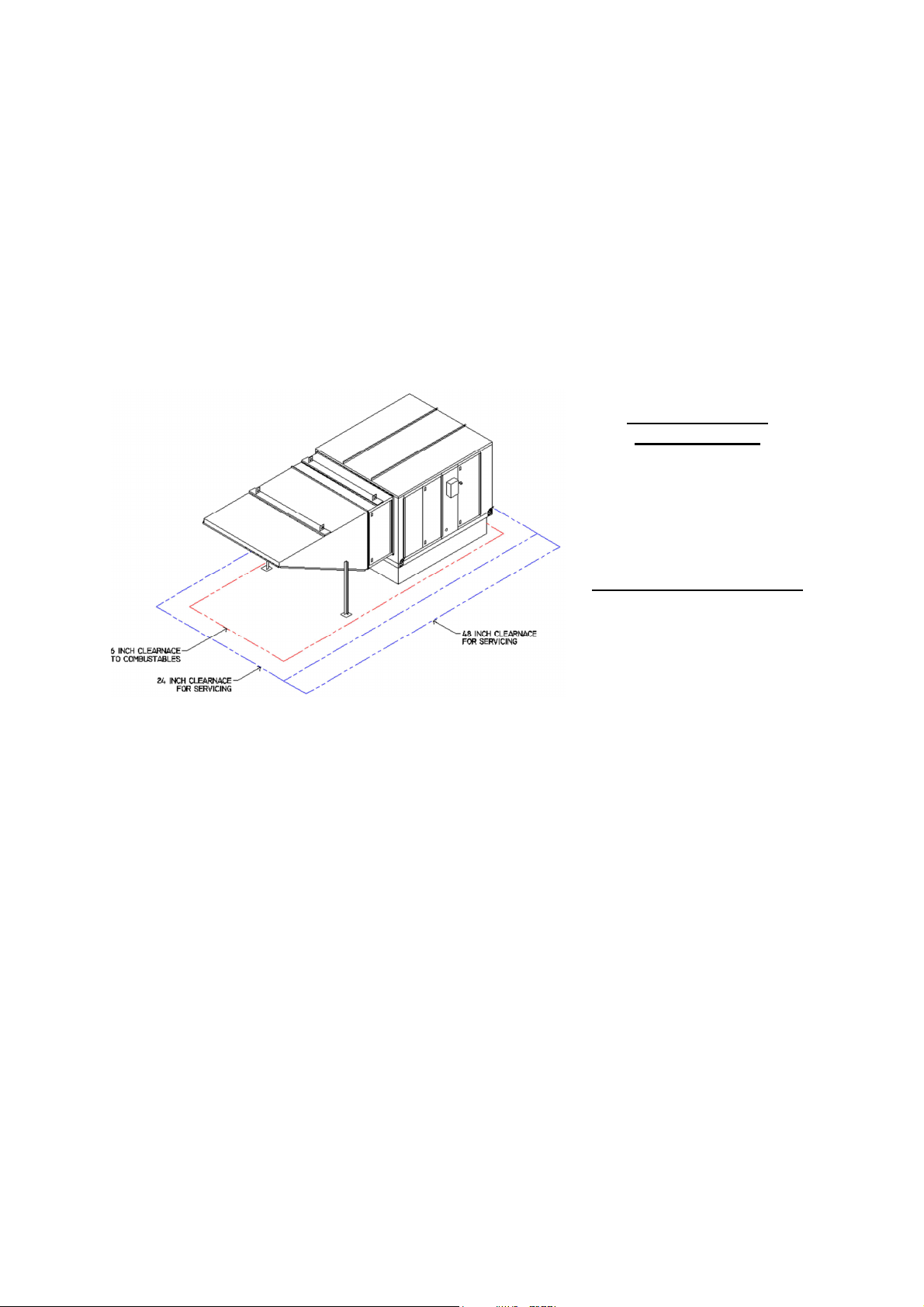
COMBUSTABLE
CLEARANCES
The top, back, and front surfaces
of this heater may not be installed
less than 6 inches from
combustible materials. The heater
base may be installed on
combustible surfaces.
SERVICE CLEARANCES
Allow 24 inches or greater
minimum service clearance on all
sides of this heater. Allow 48
inches or greater on the vestibule
and blower door side.
Rigging
1. Horizontal units are supplied with four lifting lugs on the bottom corners of the casing.
2. Vertical units are supplied with four lifting lugs at the top corners of the casings.
3. Lift the unit and accessories separately, attach the accessories to the unit once the unit is in place.
4. The following diagrams represent the proper methods for lifting the unit and accessories.
5. Always use spreader bars to prevent damage to the unit casing.
5
Page 6

FIGURE 1: SIZE 10, 12, 15, & 18 FIGURE 2: NO SPREADER BARS
FIGURE 3: WITH SPREADER BARS FIGURE 4: ACCESSORIES
CAUTION!!
These are unbalanced loads
Lift equipment gently
Do not jerk
Spreader bars must be used and should extend
past the edges of the equipment to avoid damage
to the casing. Not using spreader bars may cause
WARNING!!
WARNING!!
damage to the casing
Damage will result if the equipment is raised by the intake hood, blower, motor shaft, or bearings
Use the provided lifting eyes and brackets on the unit
Curbs
The unit must have adequate structural support or the equipment or building could be damaged. The curb
and unit must be leveled or the unit may leak or be damaged. Use gasket and caulk between the curb
and unit. Use shims if necessary to level the unit. Screw or weld the unit’s base to the curb to avoid
damage to the equipment.
6
Page 7
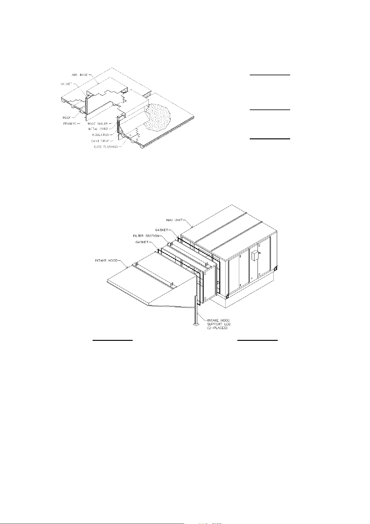
WARNING!!
The unit must have adequate structural
support or the equipment or building
could be damaged.
WARNING!!
Screw or weld the unit’s base to the curb
to avoid damage to the equipment.
WARNING!!
The curb and unit must be leveled or the
unit may leak or be damaged.
Accessories
Intake and discharge accessories are shipped loose and unassembled. When attaching the accessories
to the unit use gasket, caulk, and #10 sheet metal screws on all seams. All accessories must be level.
WARNING!!
Use gasket, caulk, and #10 sheet metal screws on
all component intersections. Leaking may result if
the intersections are not completed properly.
The accessories must be level and support legs
attached to the hood and solid part of the roof.
Equipment that is not level or properly supported
WARNING!!
may leak or be damaged.
Split Units
1. Apply weather-proof gasket to the seam of the vertical or horizontal unit
2. Use provided fasteners to secure the seam of the unit using the provided pre-punched holes
a. Horizontal units internal channels and a formed frame
b. Vertical units have angles on the outside of the casing
3. Apply silicone to the outside edge of the seam
4. Field wire the discharge air sensor using a minimum 22 gauge wire
5. Mount the high temperature limit bulb to the blower housing
6. Mount the (optional) freeze control sensor to the blower housing
7
Page 8
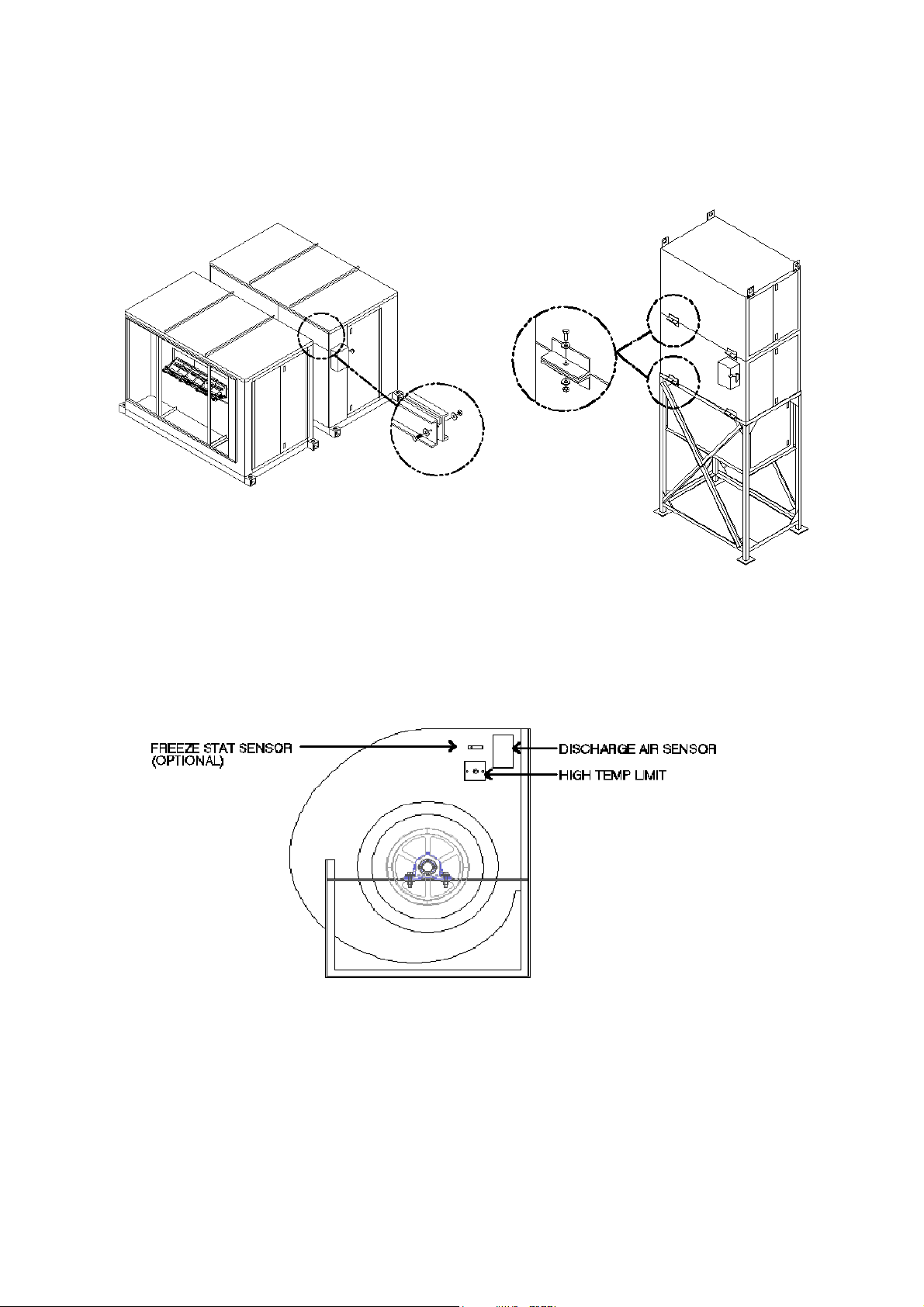
FIGURE 1: HORIZONTAL SPLIT ASSEMBLY FIGURE 2: VERTICAL SPLIT ASSEMBLY
8
Page 9
Shipped Loose Intake or Discharge Dampers
In some cases an intake or discharge damper may be shipped loose. This may be requested by the
customer or can be required because of larger units shipping size restrictions. Follow these instructions to
attach and wire the shipped loose damper. Factory mounted dampers may be attached on the unit and
will not require assembly or field wiring.
1. Attach the damper to the intake or discharge using gasket, caulk, and #10
sheet metal screws
2. Field wire the damper using the as built wiring schematic for the specific unit. Wiring may be different
depending on the model and options selected.
3. Refer to the factory supplied wiring print to verify the field wiring terminals.
Ductwork
This fan was specified for a specific CFM and static pressure. The ductwork attached to this unit will
significantly affect the airflow performance.
WARNING!!
• Flexible ductwork and square elbows should not be used
• Transitions and turns in ductwork near the fan outlet will cause system effect and will drastically
increase the static pressure and reduce airflow
• The Ductwork Sizing Chart shows the minimum fan outlet duct sizes and straight lengths
recommended for optimal fan performance
• Units with twin blower must have a common discharge plenum
Follow SMACNA guides and recommendations for the remaining duct run. Fans designed for
rooftop installation should be installed on a prefabricated or factory-built roof curb. Follow curb
manufacturer’s instructions for proper curb installation. It is recommended an outdoor unit be installed on
a curb and/or rail elevated so intake is not less than 20” above any surface. Be sure the duct connection
and fan outlet are properly aligned and sealed.
Adequate building relief is necessary in order to prevent over-pressurizing the building when the heater is
operating at capacity. This can be accomplished by establishing properly-sized relief openings, an
interlocked exhaust system, or both.
Heaters installed with intake ductwork must be purged to replace at least four air changes of the volume
of the intake duct.
In order to avoid hazards to other fuel-burning equipment in the building (i.e., when the heater is providing
make-up air to a boiler room), the unit should be interlocked to open inlet air dampers or other such
devices.
On outdoor installations, it is recommended that the discharge duct be insulated to prevent condensation
during the “OFF” cycle in cold weather.
Units being installed in airplane hangars should be installed in accordance with the Standard for Aircraft
Hangars, ANSI/NFPA 409. Units being installed in public garages should be installed in accordance
with the Standard for Parking Structures, ANSI/NFPA 88A, or the Standard for Repair Garages,
ANSI/NFPA 88B, and with CAN/CGA B149 Installation Codes.
Flexible connectors should be employed on all ductwork connections. Vibration isolators are optional and
can be supplied in the loose parts package.
Ductwork Sizing Chart Single Blower
Blower Size
Duct Size
(Inches)
Duct Length
(Inches)
Ductwork Sizing Chart Dual Blowers
Blower Size
Duct Size
(Inches)
Duct Length
(Inches)
9
Page 10

10 14 x 14 30
12 16 x 16 36
15 20 x 20 45
18 24 x 24 54
20 26 x 26 60
22 30 x 30 66
25 32 x 32 75
27 36 x 36 81
30 38 x 38 90
33 44 x 44 99
36 44 x 44 108
Installation Examples
222 77 x 28 66
225 88 x 32 75
227 96 x 36 81
230 104 x 38 90
233 116 x 44 99
236 122 x 44 108
WARNING!!
Failure to undersize ductwork size or length
may cause system affect and reduce the
performance of the equipment.
Using the unit to support the ductwork may
cause damage to the units casing.
Figure 1: Horizontal Roof Top Installation
Down discharge AMU reduces ductwork
Hood weight supported by support legs
Union, regulator, and shut-off
Roof curb supports unit
Intake facing away from prevailing winds
Figure 2: Vertical Outdoor Ground Installation
Side discharge AMU reduces ductwork
Support stand on concrete pad
Union, regulator, and shut-off
Filter section inside support stand
Ease of serviceability on ground
10
Page 11

Gas
Gas piping must be installed to conform with local building codes, or in the absence of local codes, the
National Fuel Gas Code, ANSI Z223.1 (NFPA 54) – latest edition. In Canada, gas piping must be
installed in accordance with CAN/CGA-B149.1 for natural gas units and CAN/CGA-B149.2 for propane
units.
WARNING
Inlet gas pressure must not exceed pressure
indicated on name plate.
Refer to the heater rating plate for
determining the minimum gas supply
pressure for obtaining the maximum gas
capacity for which this heater is specified.
1. Always disconnect power before working
on or near a heater. Lock and tag the
disconnect switch or breaker to prevent
accidental power-up.
2. Piping to the unit should conform to local
and national requirements for type and
volume of gas handled, and pressure drop
allowed in the line. Refer to the Gas
Engineer’s Handbook for gas line capacities.
3. The incoming pipe near the heater should
be sized to match the connection on the
outside of the unit. Unit inlet sizes are shown
in the table to the right. Avoid multiple taps
in the gas supply so the unit has a steady
supply of gas at all times.
4. Install a ground joint union with brass seat
and a manual shut-off valve external to the
unit casing, as shown below, adjacent to the
unit for emergency shut-off and easy
servicing of controls.
5. Provide a sediment trap, as shown below,
before each unit and where low spots in the
pipe line cannot be avoided.
6. Blow out the gas line to remove debris
before making connections. Before starting
the unit, purge line to remove air. Purge air
from gas lines according to ANSI Z223.1latest edition “National Fuel Gas Code,” or in
Canada: CAN/CGA-B149.
7. All field gas piping must be pressure/leak
tested prior to operating the unit. Use a
soap solution or equivalent for leak testing.
The heater and its individual shut-off valve
must be disconnected from the gas supply
piping system during any pressure testing of
that system at test pressures in excess of ½
PSI. During any pressure testing of the gas
supply piping system at test pressures equal
to or less than ½ PSI, the heater must be
isolated from the gas supply piping system
and its individual manual shutoff valve
closed.
8. This unit requires the gas pressure to be
within the unit’s minimum and maximum gas
pressure ratings. If the pressure is greater
than the maximum, the internal valve
components will be damaged. If the
pressure is below the minimum, the heater
will not perform to specifications.
9. If installing on a paint booth application, a
manual shutoff should be located for access
in case of a fire or explosion at the heater.
Gas Connection Sizes
BTU Input
158,000
275,000
549,999
1,099,999
1,374,999
1,649,999
1,924,999
2,474,999
2,749,999
3,574,999
4,124,999
5,224,999
5,774,999
7,974,999
8,524,999
9,624,999
11,274,999
11,824,999
12,924,999
16,847,999
Gas Pressure (Inches W.C. & PSI)
7” – 14” 15” – 1# 1# - 5#
½ ½ ½
¾ ½ ½
¾ ¾ ¾
1 ¾ ¾
1 ¼ ¾ ¾
1 ½ 1 1
2 1 1
2 1 ¼ 1
2 1 ½ 1
2 2 1 ¼
2 2 1 ½
2 ½ 2 2
2 ½ 2 2
2 2
2 ½ 2
2 ½ 2
2 ½ 2
3 2
3 2 ½
3
11
Page 12
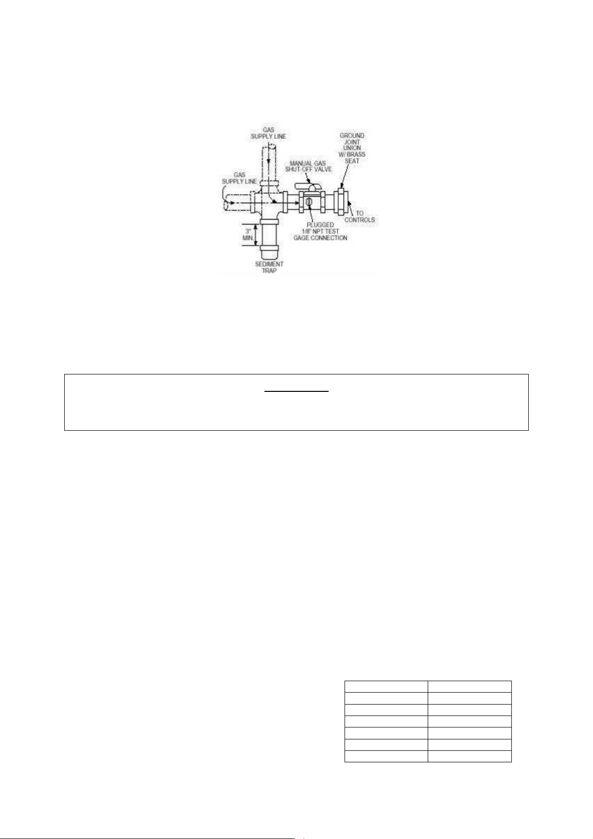
Gas Connection Diagram
Electrical
Before connecting power to the heater, read and understand this entire section. Wiring diagrams are
furnished with each fan by the factory, and are attached to the door of the unit.
WARNING!!
Disconnect power before installing or servicing fan. High voltage electrical input is needed for
this equipment. This work should be performed by a qualified electrician.
Electrical wiring must be done in accordance with local ordinances and the National Electric Code,
ANSI/NFPA70. Be sure the voltage and phase of the power supply and the wire amperage capacity
conform to those listed on the motor nameplate. For additional safety information, refer to AMCA
publication 410-96, “Recommended Safety Practices for Users and Installers of Industrial and
Commercial Fans.”
1. Always disconnect power before working on or near a heater. Lock and tag the disconnect switch
or breaker to prevent accidental power-up.
2. A dedicated circuit should supply the units electrical disconnect with circuit protection, according to
the National Electric Code.
3. Make certain that the power source is compatible with the requirements of your equipment. The
heater nameplate identifies the proper phase and voltage of the motor.
4. Units shipped with an optional remote panel have two electrical circuit. It is important to run the motor
wires in a conduit separate from the remote control wiring. The DC wires from the unit temperature
controller, located in the control drop, should be either in shielded cable or run in a separate conduit.
5. Before connecting the heater to the building power source, verify the power line wiring is deenergized.
6. Secure the power cables to prevent contact with sharp objects.
7. Do not kink power cable and never allow the cable to come in contact
with oil, grease, hot surfaces or chemicals.
8. Before powering up the heater, check fan wheel for free rotation and
make sure that the interior of the heater is free of loose debris or
shipping materials.
12
Copper Wire Ampacity
Wire Size AWG Maximum Amps
14 20
12 25
10 30
8 40
6 55
4 70
Page 13

9. If necessary, the original wire supplied with the heater may be replaced with type TW wire or the
equivalent.
Remote Control Panel
For units with the remote control panel, a terminal strip inside the panel matches the terminals in the
heater unit. Consult the as built wiring print supplied with the equipment. Most remote panels and VAV
applications have signal wiring which needs to be shielded cable or in a separate conduit to avoid voltage
interference.
Power Supply Wiring
The units input power supply is listed on the unit nameplate. If the units power supply does not match the
unit nameplate contact the service department for a new wiring print and parts.
Paint Booth Applications
If a low temperature control is not an integral part of the heater, it is recommended that one be installed in
areas where freeze protection is needed in the event of a burner shutdown. The space should be
ventilated following a bake cycle to purge any contaminants and cool product prior to personnel entering
the space. If the unit was supplied with paint booth controls from the factory, refer to the schematic for
installation of the interlock to disable spraying equipment unless the heater is operating in ventilation
mode. Refer to electrical schematic for interlock to disable facility lighting within the process space during
the bake cycle.
SEQUENCE OF OPERATIONS
Description of Operation
Designed for indoor or outdoor installation, the Direct Fired Gas Heater draws fresh outside air over a
gas-fired burner. The unit is equipped to fire with natural or propane gas. Units are designed for
modulated firing of the burner, based on the discharge-air temperature or room temperature requirement.
Standard Sequence of Operation
1. With disconnect in ON position and the remote control panel (or other device) calling for unit
operation, power is supplied to the damper motor, if equipped.
2. When the damper motor approaches the OPEN position, the damper-end switch closes, energizing
the motor contactor and powering the blower motor or enabling the VFD if equipped.
3. Power is supplied to the damper motor through the low-temperature limit control, if equipped. After
ten minutes, the low-temperature limit control disables the unit if discharge temperature is continually
below the temperature setting on the low limit control.
4. When the low airflow switch and high airflow switch (VFD only) are proven, the flame safety relay is
energized through the high-temperature limit control, the optional low and/or high gas pressure
switches, and the burner on/off intake air thermostat. The pilot valve opens, and the ignition
transformer energizes.
5. After the flame rod detects flame, the main valves are energized and the ignition transformer deenergizes.
6. The temperature control system monitors the discharge air and modulates DC voltage to the
13
Page 14

modulating valve to maintain desired discharge temperature.
Additional Sequence of Operation – All VFD Motor Control
1. During lower speeds, the low-speed potentiometer increases the resistance going to the modulating
valve to limit temperature rise.
2. VFD contacts are included in the burner control circuit to disable the burner should a fault condition
occur in the VFD.
VFD by Others and VAV Choke Off Profile Bypass Damper
As the VFD increases and decreases speed the profile air flow switch modulates the VAV bypass
damper motor to maintain proper pressure drop across the burner profile.
Factory VFD Profile Bypass Damper
The VFD produces a 0-10vdc or a 4-20ma signal to the profile damper motor which modulates
the profile damper’s opening to maintain the burner profile pressure drop. The range of this
modulation must coincide with the VFD operating range.
VFD Preset Speeds
1. Inputs are made to the VFD to engage programmable pre-set speeds. A factory-supplied VFD wiring
and programming instruction sheet comes with every unit. Consult the as-built schematics and the
VFD manual for additional information.
Manual Potentiometer Adjustment – VFD and Choke-Off Dampers
1. A 10k-15k ohm potentiometer may be field supplied and installed if remote manual control is required
for the VFD. See VFD manual for proper installation.
2. A 135 ohm potentiometer is used for remote manual control of choke-off vav dampers.
Static Pressure Control (Photohelic) – VFD and Choke-Off Dampers
The VFD or Choke-off dampers can be controlled by a building static pressure control. This controller will
sense the difference between pressure inside the building, and pressure outside the building and will
control the operating speed of the VFD or position of choke-off dampers to maintain the pressure setting
on the controller. The controller has two set points and an indicator. The two set points are a minimum
desired static pressure point, and a maximum static pressure point.
When building static pressure is below the minimum setting, the VFD will increase the blower RPM or
choke-off damper will open to increase airflow. If the building static is above maximum setting, the VFD
will decrease the blower RPM or close choke-off dampers. When building static pressure is between the
minimum and maximum settings, no signal is given to change VFD speed or choke-off damper position.
See additional wiring and installation information on the static pressure controller and outdoor sensor.
The static pressure controller can be ordered to be shipped loose or mounted inside the unit to reduce
field wiring and assembly.
14
Page 15
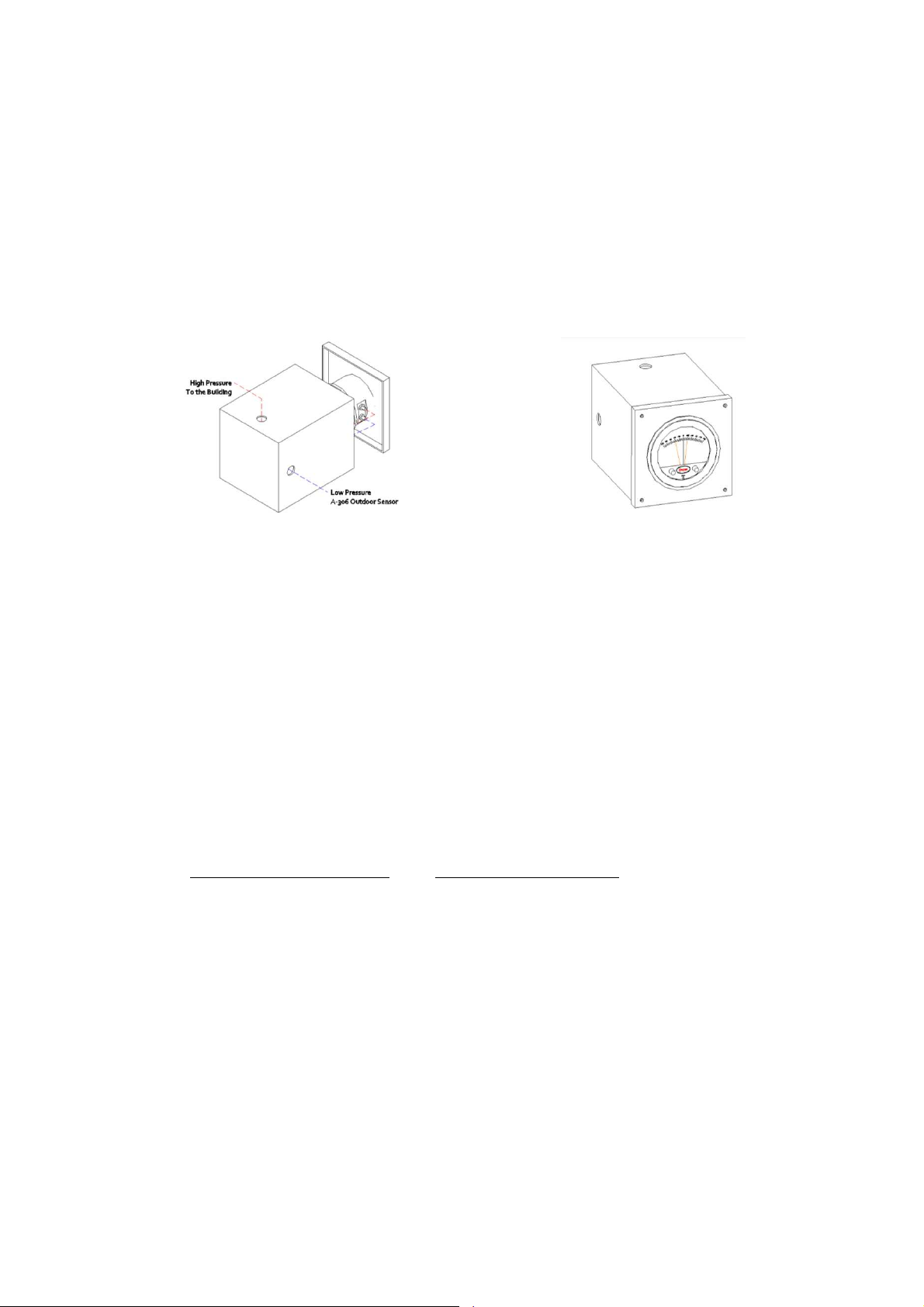
Static Pressure Controller Installation Instructions
Avoid locating the front of the static pressure controller in sun light or other areas with high ambient light
or corrosive levels. Bright light shining on the photocells can cause false actuation of the load relays.
The static pressure controller should be zeroed out before attaching the low and high pressure hoses.
The zero adjustment is located between the minimum and maximum dials.
Using the supplied rubber tubing the high side of the static pressure controller should be plumbed to the
inside of the building. The low side of the static pressure controller should be plumbed to an outdoor
sensor.
Outdoor Sensor
Use the installation instructions shipped with the outdoor sensor.
START-UP PROCEDURE
Check for signs of damage. Do not operate if damage exists and contact your manufactures sales
representative. Units are easier to fix before the equipment is installed.
Check all installation clearances.
Clearance from Combustibles Clearance for Serviceability
Top: 6” Sides: 6” Base: 0” Unit: 24” Service Accesses: 48”
Check that the unit has been set level and secured.
Unit must have adequate structural support or the equipment or building may be damaged.
Curb and unit must be leveled or the unit may leak or be damaged.
Gasket and caulk the seam between the curb and unit base
Screw or weld the unit’s base to the curb to avoid damage to the equipment.
Check that the accessories are set level and secured.
Accessories must have adequate structural support or the equipment or building may be damaged
Gasket, caulk, and screw each accessory to unit seam
Check that the unit’s intake and discharge are free of debris
Check that the filter are installed in the (optional) filter section or intake hood in accordance to the air
flow direction
Check that the unit’s ductwork size and length match the minimum ductwork size chart
Check that all field wiring has been completed in accordance to the factory supplied wiring diagram
Field wires are shown as dashed lines on the wiring prints
15
Page 16
Check that all terminal screws are tight and that wires are in place
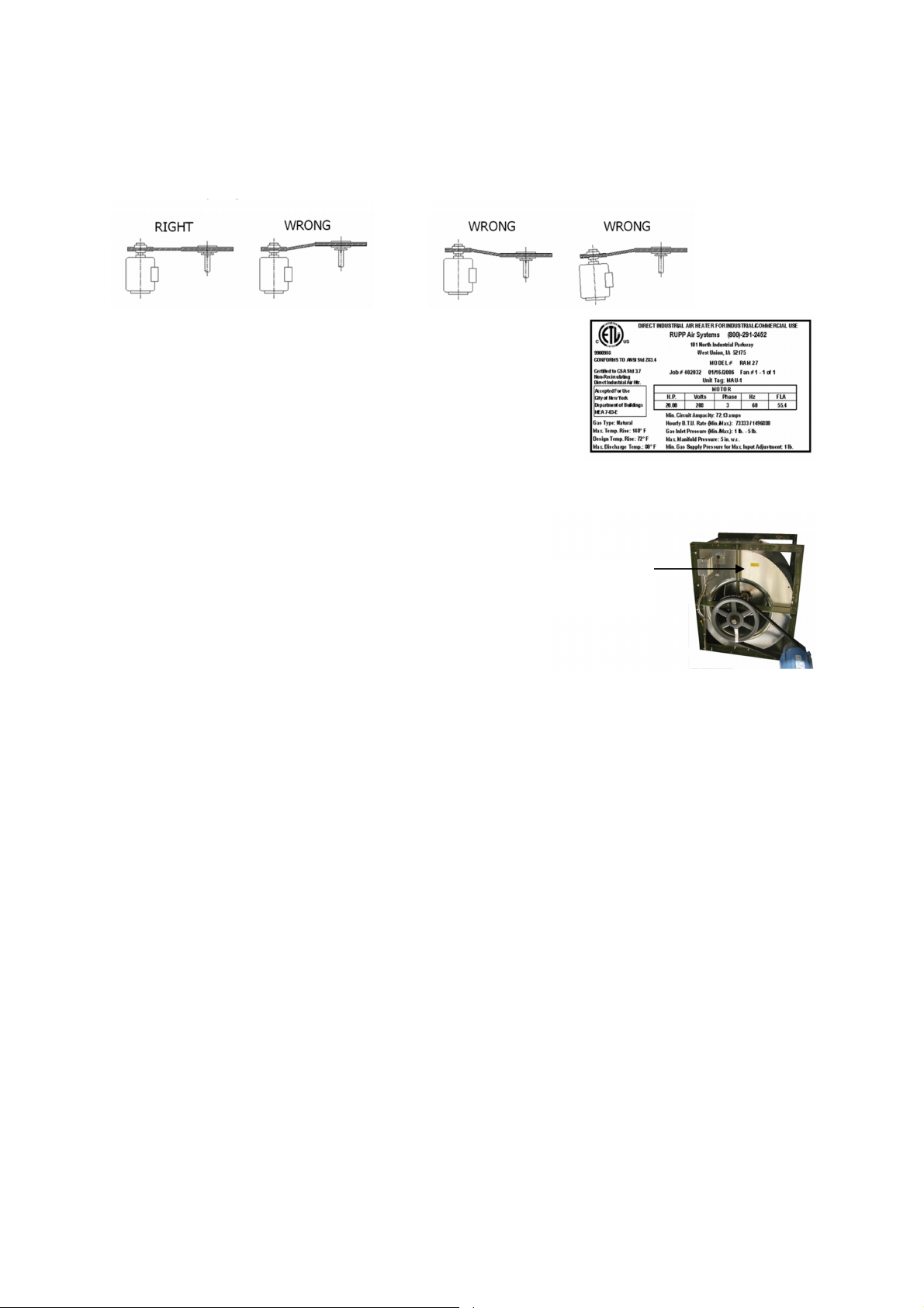
Check pulley alignment. Correct if necessary
Check that the power supply matches the nameplate
voltage, phase, and amperage
Record the voltage on the Start-Up Sheet
Check that the gas type and pressure matches the
nameplate type and pressure
Check that the gas type and pressure matches the
nameplate type and pressure
Contact the service department is the power or gas
supply needs to be changed in the field. Different parts
might be necessary for the change
Turn the remote panel switch to OFF if blower and burner
service switches were supplied
Set the temperature set point dial to the maximum
Turn the main power disconnect ON
Bump the blower motor starter to check the blower
wheel rotation
The decal is located on the blower housing
If the rotation is backwards turn off the power and
correct the wiring
The rotation can be corrected by interchanging two
legs of 3 phase (must be between vfd and motor on vav units)
ROTATION
DECAL
16
Page 17
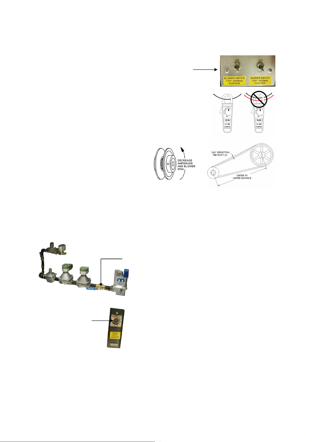
Turn the blower service switch or remote
control device to ON. The (optional) intake
or discharge damper motor will start to
open. Once the damper is 90% open the
BLOWER
SERVICE
SWITCH
damper motor internal end switch will close
and energize the blower motor starter.
Check that the motor amp draw is less than
the FLA (full load amps) of the blower
motor.
The fan RPM may need to be reduced
to decrease motor amps.
Opening the driver (motor) pulley
decreases RPM and motor amps.
Closing the driver pulley increases
RPM and motor amps.
Record the motor amps on the Start-
Up Sheet.
If the RPM was adjusted in the field use a
tachometer to record the new RPM on the
Start-Up Sheet.
Check the belt tension after any RPM
adjustments. See the belt tension detail.
Check the air flow pressure drop.
The air flow switch on single speed units is a low air flow switch only and opens below 0.15 in w.c.
The target pressure drop range for the single speed unit is 0.40 – 0.50 in w.c.
Do not adjust airflow switches
Use the profile plates or blower RPM to increase or decrease the pressure drop.
Record the pressure drop on the Start-Up Sheet.
Close the burner gas shut off valve
This will allow the unit to fire the pilot only and will be opened at a later time
CLOSE VALVE
Set the Burner Intake On Off Switch is set above the outside air temperature
SET DIAL 10
DEGREES ABOVE
OUTDOOR TEMP
Turn the burner service switch or remote control to ON
The Fireye Flame Safety Control energizes the ignition transformer and pilot gas valve
After the pilot flame is established, the main gas valves will open
At this time the pilot will be the only flame in the burner
The pilot regulator should be adjusted so the pilot flame signal is stable 6-18 VDC
17
Page 18
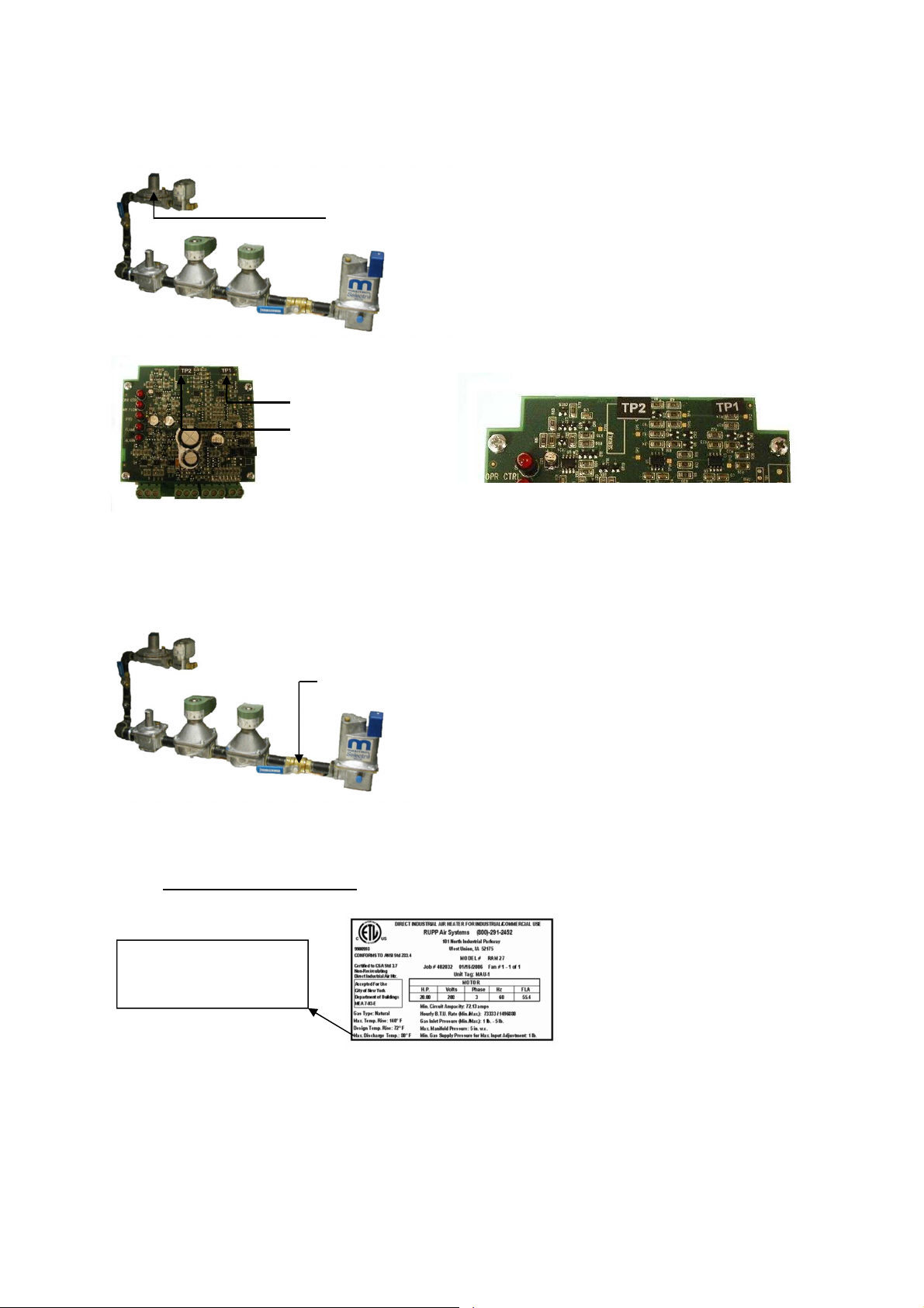
PILOT REGULATOR
+
Use the DC terminals on the flame safety to read the pilot flame signal
POSITIVE TERMINAL
NEGATIVE TERMINAL
Record the pilot flame signal in the Start-Up Sheet
Record the low and high fire flame signal on the Start-Up Sheet
Setting High Fire
Open the Burner Gas Shut Off Valve
OPEN VALVE
Measure the intake air temperature.
Add the intake air temperature to the units nameplate design temperature rise.
This result will be the desired high fire discharge temperature.
Example: Intake Temp 70 F
Design Temp Rise 72 F
Discharge Temp 142 F
GAS TYPE: NATURAL
MAX. TEMP. RISE: 140 F
DESIGN TEMP. RISE: 72 F
MAX. DISCHARGE TEMP.: 80
18
Page 19
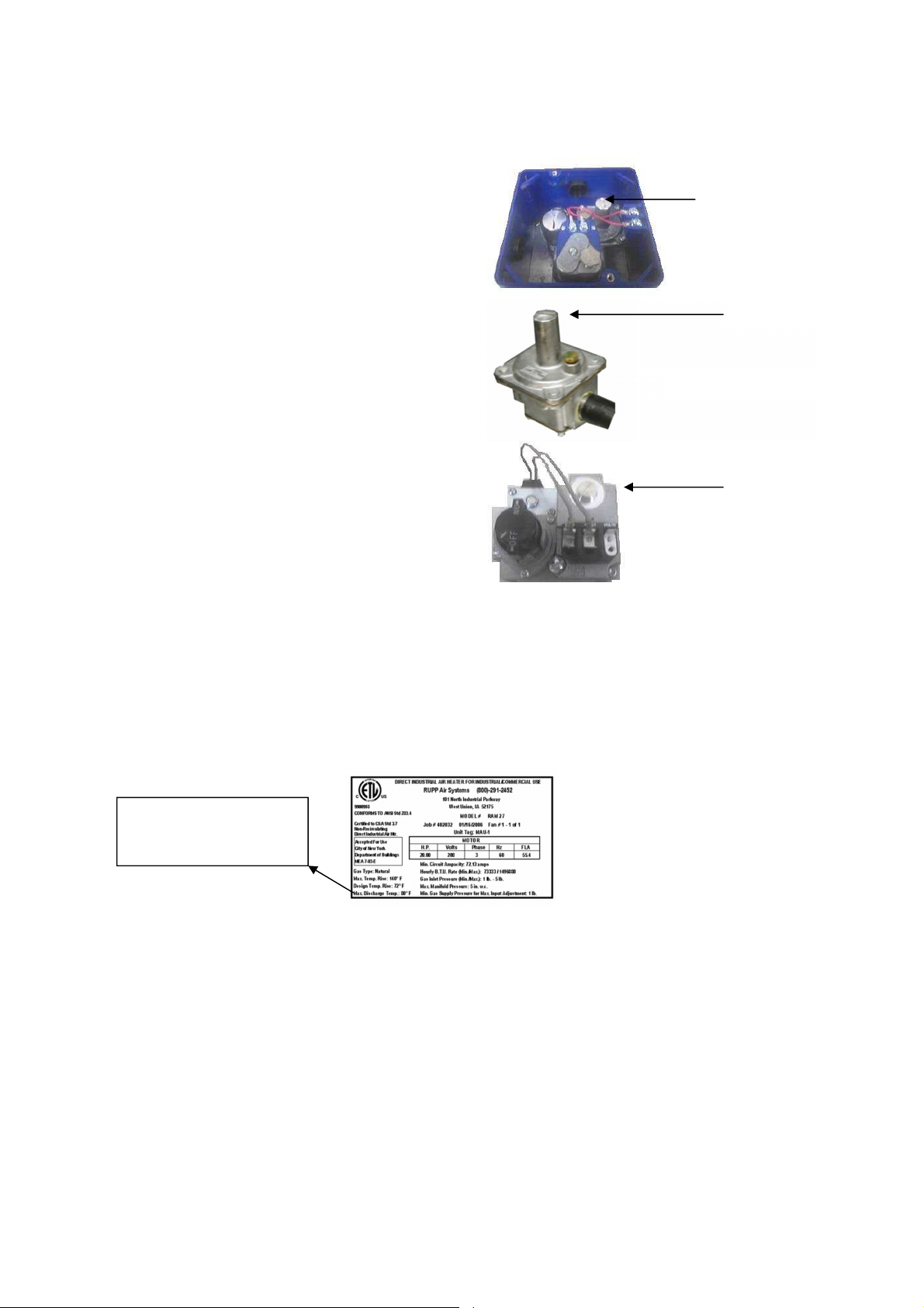
Use the Amplifier to override the heater into high
fire.
On discharge temperature control amplifier
remove the #4 wire
On the space temperature control amplifier
remove the #2 and #4 wire
On the M-Series adjust the set-point to be
160 F
Adjust the manifold gas pressure to achieve the
desired discharge air temperature.
See the details for the high fire pressure
adjustment locations.
On manifolds with an MR212 modulation
valve, adjust the small regulator inside the
MR212 modulation valve
On manifolds with either an M511 or M611
modulation valve, adjust the regulator located
before the main gas valves
On manifolds with a combination gas valve,
adjust the regulator under the brass cap on
the combination gas valve.
Measure the discharge temperature using a
thermometer. Laser thermometers are not as
accurate as a thermocouple type.
If the discharge ductwork outlet is hard to reach,
you may feed a thermocouple into the mixing tube inside the blower discharge.
HIGH FIRE
HIGH FIRE
HIGH FIRE
Setting High Fire – Manifold Pressure Method
Turn the burner service switch OFF
Measure the manifold pressure with the burner in high fire as described above
Adjust to match design manifold pressure on nameplate
Measure discharge temperature and calculate temperature rise as described above to account for
variances in airflow from design
GAS TYPE: NATURAL
MAX. TEMP. RISE: 140 F
DESIGN TEMP. RISE: 72 F
MAX. DISCHARGE TEMP.: 80
19
Page 20
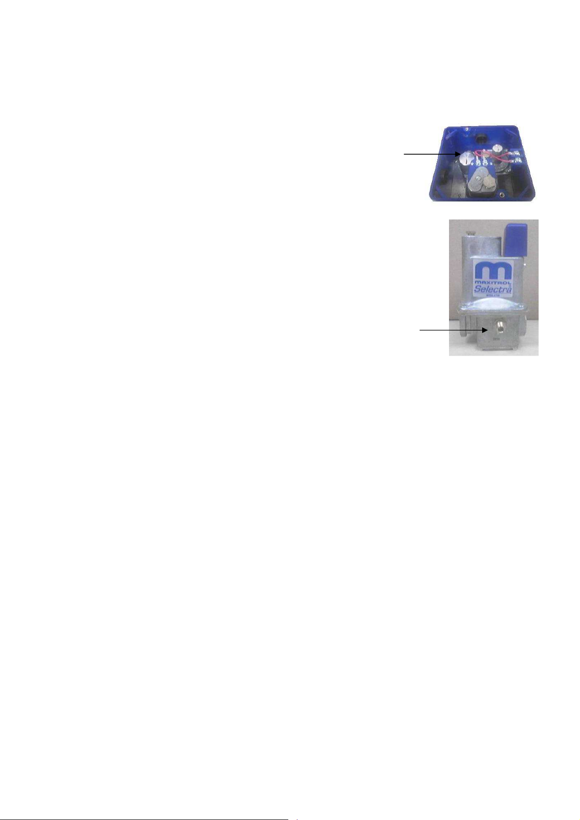
Setting Low Fire
Disconnect power to the amplifier or modulating
valve
Adjust the low fire setting on the modulation valve so
the flame is full length of burner without dark spots
See the details for the low fire pressure adjustment
locations
Use the burner observation port on the end of the
unit to view the flame size
Replace all amplifier wires in the place they were
removed to set high and low fire
Additional capacity is provided via a low fire bypass
when MR212 low fire capacity is insufficient. Additional
adjustment is made via the R400S regulator installed in
the low fire bypass.
LOW FIRE
Final Start-Up
Set the Burner Intake On-Off Thermostat to the desired temperature to disable burner
This will automatically open the burner circuit when the outside air is above the selected
temperature
Turn the blower and burner service switches OFF
Now the unit will be operated from the control panel only
Operate the unit from the remote panel checking the lights, switches, set-points, and optional
thermostats or timers
Review the proper operation and sequence of operation with the customer to ensure that the unit is
operated properly and that the customer does not misuse the equipment
Complete the Start-Up Sheet and fax it to the service department to validate the warranty
LOW FIRE
START-UP PROCEDURE VARIABLE AIR VOLUME
The Start-Up procedure for variable air volume units is the same as the single speed unit except there are
additional steps for checking burner pressure drop and setting high/low fire. Use the single speed
procedure along with these additional steps for the vav start-up procedure.
Check the air flow pressure drop through entire airflow range.
The air flow switch on vav units is a low (0.15) and (0.65) high switch
Do not adjust airflow switches
Use the profile plates, choke-off dampers or VFD to increase or decrease the pressure drop.
Record the pressure drops on the Start-Up Sheet.
Verify the flame limiting device is functioning properly in low speed on units with a vfd.
Verify low fire setting at minimum flow rate as well.
20
Page 21
WARNING!!
PROFILE ADJUSTMENTS
The Direct-Fired Gas, make-up heater requires the correct air flow velocity across the burner. The air
flow switch monitors the profile pressure differential, and will open the burner circuit if pressure difference
is not within the allowed range. The air flow switches have low and high pressure settings for variable air
volume units. The pressure drop should not be near the minimum and maximum of the air flow switch.
Profile adjustment may be required to fine tune the burner profile pressure drop. See the specifications
and instructions below on air balancing a 100% fresh air heater.
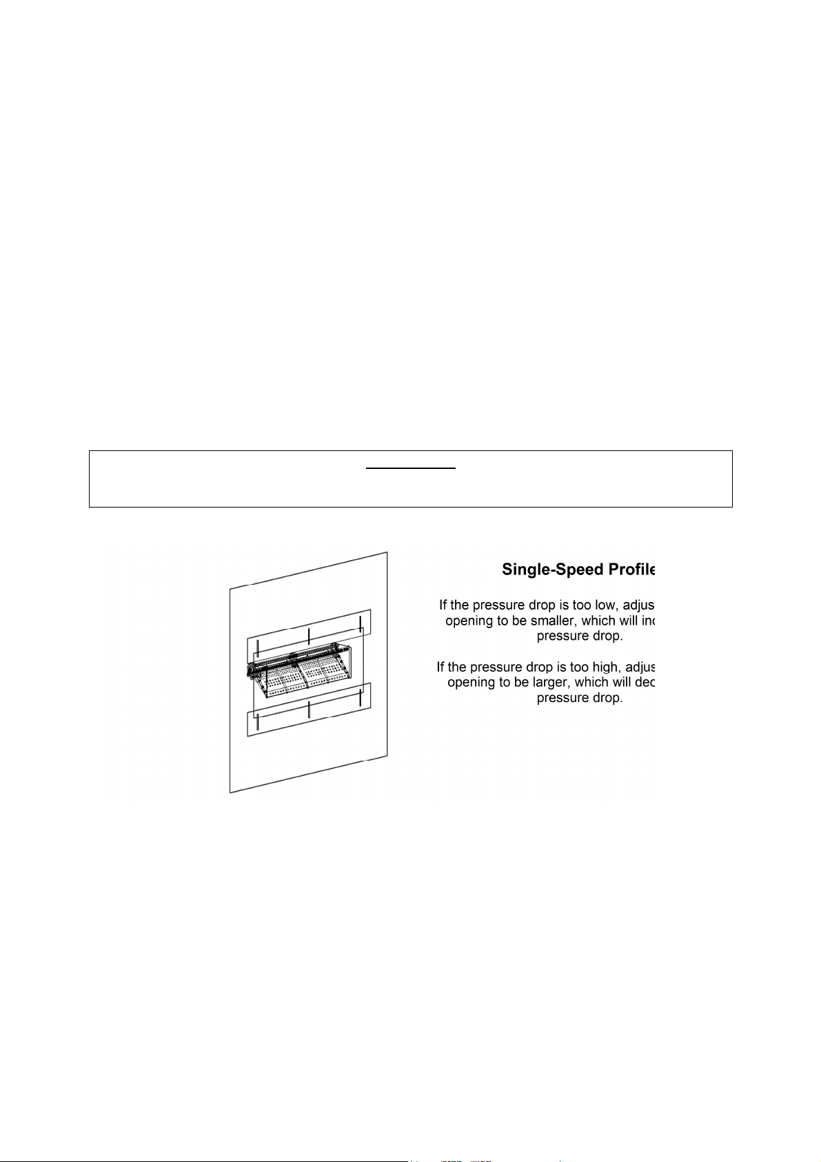
Single-Speed Profile
The pressure drop should be checked with the burner OFF if ambient temperature is greater than 60
degrees Fahrenheit. If the ambient temperature is lower than 60 degrees Fahrenheit, the burner should
be operating and discharging approximately 70 degrees Fahrenheit. An extra set of airflow probes have
been installed to ease in checking profile differential.
Disconnect power and close all gas valves before and while making burner profile adjustments.
Single-Speed Profile
If the pressure drop is too low, adjust the profile
opening to be smaller, which will increase the
pressure drop.
If the pressure drop is too high, adjust the profile
opening to be larger, which will decrease the
pressure drop.
21
Page 22
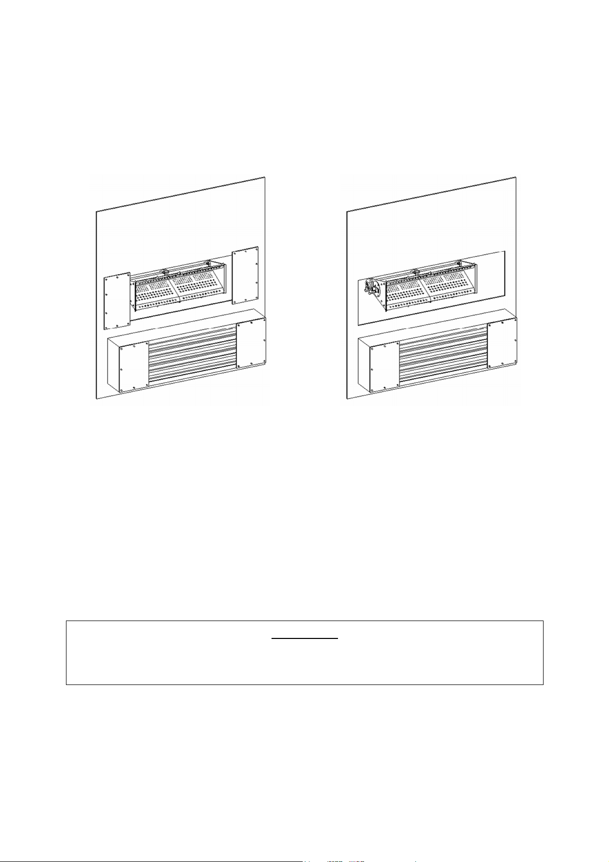
Variable Air Volume Profile
VAV Profile
In low speed, adjust the burner profile opening
smaller to increase pressure drop or larger to
lower pressure drop.
VAV Profile
In high speed adjust the bypass damper opening
larger to decrease the pressure drop and
smaller to increase the pressure drop.
VFD Drive Installation & Programming Instructions
WARNING!!
-Before installing the VFD drive, ensure the input power supply to the drive is OFF
-The power supply and motor wiring of the VFD must be completed by a qualified electrician
-The programming of the VFD must be completed by a qualified HVAC technician
Consult the VFD manual and all documentation shipped with the unit for proper installation and
wiring of the VFD.
The VFD has been programmed by the factory with order specific parameters.
22
Page 23

Check Installation:
√
Check
The installation environment conforms to the VFD manual.
The drive is mounted securely.
Space around the drive meets the drive’s specification for cooling.
The motor and driven equipment are ready for start.
The drive is properly grounded.
The input power voltage matches the drive’s nominal input voltage.
The input power connections at U1, V2, and W1 are connected and tight.
The input power protection is installed.
The motor power connection at U2, V2, and W2 are connected and tight.
The input, motor, and control wiring are run in separate conduit runs.
The control wiring is connected and tight.
NO tools or foreign objects (such as drill shavings) are in the drive.
NO alternative power source for the motor (such as a bypass connection) is
connected - NO voltage is applied to the output of the drive.
TEMPERATURE CONTROL SYSTEMS
401M
402M
403M
404M
• The 401M replaces building-exhaust air with tempered make-up air.
• A discharge-sensing controller that compensates for intake air temperature changes modulates
the burner flame.
• A manual, remote selector switch controls the unit’s operation.
• The 402M is used primarily in door-heater applications. The space override thermostat increases
the discharge-air temperature when needed to maintain temperature.
• The amount of override temperature is controlled via a 0-40 degree potentiometer on the side of
the temperature set point dial.
• A manual, remote selector switch may control the unit’s operation.
• The 403M maintains a constant space temperature.
• A modulating space thermostat adjusts the burner to maintain the supply-air temperature
necessary to compensate for changes in the building’s heat requirement.
• The amplifier limits the maximum and minimum temperature of the supply air the unit delivers.
• A manual, remote selector switch may control the unit’s operation.
• The 404M maintains a constant space temperature, day or night. During day operation, a
modulating-space thermostat adjusts the burner to maintain the supply-air temperature necessary
to compensate for changes in building’s heat requirements.
• The amplifier limits the maximum and minimum temperature of the supply air the unit delivers.
• During night operation, a space thermostat cycles the unit ON or OFF to maintain the space
temperature.
• A manual remote selector switch may control unit operation.
•
The DAY/NIGHT mode is automatically controlled via a programmable thermostat or time clock.
23
Page 24
Flame Safety Controller
High Temperature Limit
Signal Conditioner
• When computer of other process controls are specified, the signal conditioner provides
compatibility with modulator / modulator-regulator valves.
• This system requires a field supplied 4 to 20 milliamp or 0 to 10 DC voltage signal.
OTHER UNIT COMPONENTS
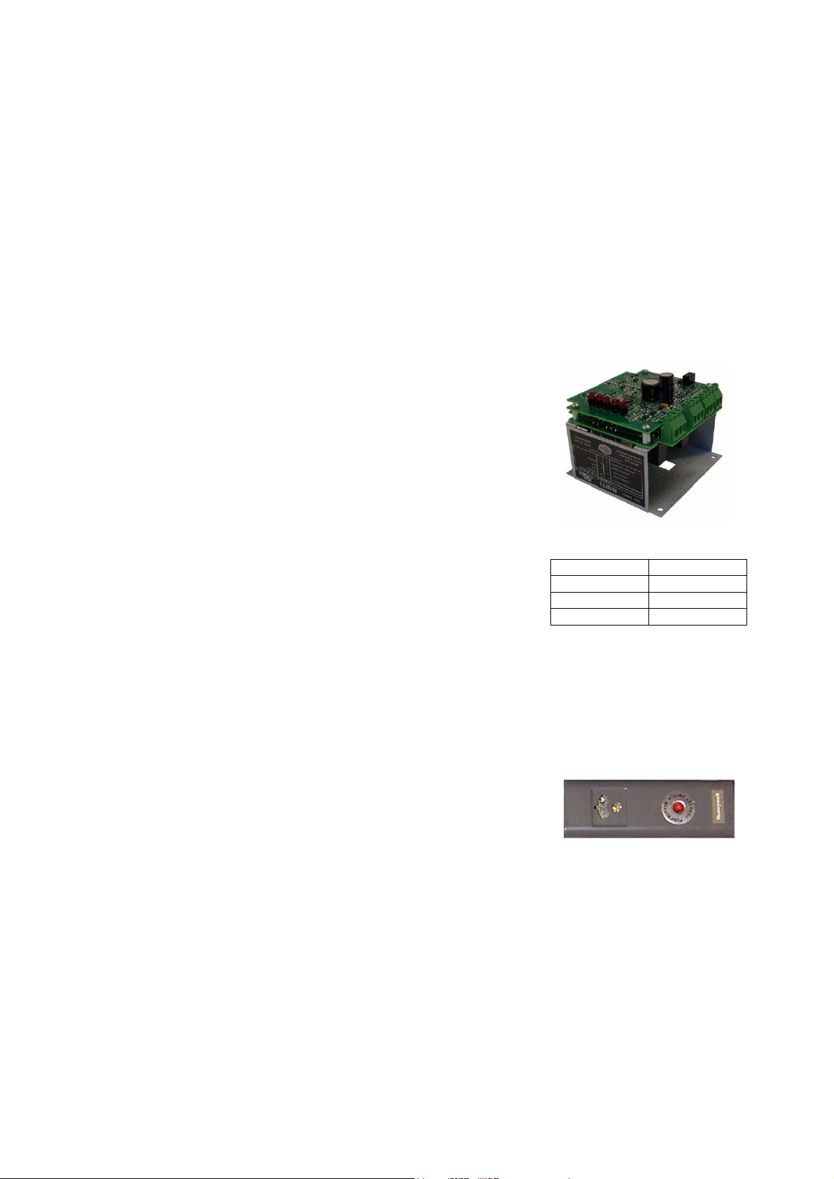
Flame Safety Control
The first system to understand is the Flame Safety Control. The FSC is
there only to monitor the flame, NOT to control temperature. The FSC
uses a flame rectification sensor (flame rod) mounted on the pilot
assembly to detect the presence of flame in the burner. Flame strength
and presence can be measured at the FSC by reading the rectified flame
signal using a DC voltage meter in the test jacks. Flame is present when
the DC voltage reads between 6 and 18 VDC. Ideal flame intensity
produces a signal of 12 VDC or greater. The FSC controls the opening of
the main and pilot gas valves and the operation of the spark igniter to
initiate a pilot flame upon start-up.
The OPR CTRL LED indicates that there is power to the FSC. Next, the
AIRFLOW LED will come on if there is proper airflow through the unit.
Third, the unit will pause to purge any gasses or combustible vapors
before attempting flame ignition. Then, there is a Pilot Trial For Ignition
(PTFI) and the PTFI LED comes on. During PTFI, the FSC opens the pilot
gas valve and allows gas to flow to the pilot assembly. At the same
moment, the spark igniter is started, causing the spark to ignite the pilot
gas. When the flamerod sensor detects the flame, it turns on the FLAME
LED, turns off the PTFI LED. This is the normal operating mode. The last
LED on the FSC is the ALARM LED. This will turn on when the FSC determines an unsafe condition has
occurred, and will not allow the unit to recycle for heat until it has been properly reset. Anytime the FSC
has gone into “Alarm” mode, the problem must be diagnosed and corrected to avoid future lockouts after
resetting. To reset the FSC, cycle power to the control. This will clear the alarm from the flame safety.
DC Flame Signal
DC Voltage Flame Status
0 to 5 VDC No Flame
6 to 11 VDC Weak Flame
12 to 18 VDC Strong Flame
High Temperature Limit
One of the safety device is the high temperature limit switch. This switch is a
mechanical thermostat that measures the temperature inside the unit downstream of the
burner. If the factory-set temperature is exceeded, it will disable the burner. This
requires a manual reset of the high temperature limit.
Electric Cabinet Heater
On units shipped with an optional electric cabinet heater, ensure that the heater is wired to a separate
120V, 15 amp input, the thermostat sensing bulb is mounted correctly in the control vestibule where the
heater is located, and the thermostat set to 0 Degrees Fahrenheit.
24
Page 25
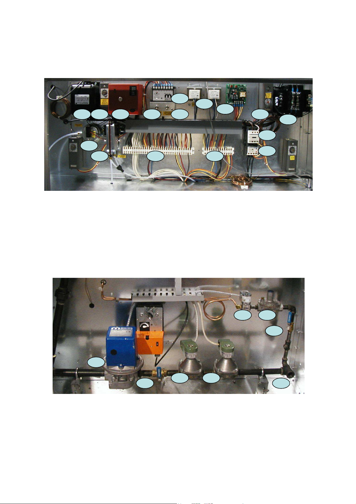
ELECTRICAL VESTIBULE
1. IGNITION TRANSFORMER
2. INTAKE AIR THERMOSTAT
3. FLAME SFAETY CONTROL
4. MODULATING AMPLIFIER
5. BLOWER SERVICE SWITCH
6. BURNER SERVICE SWITCH
7. CONTROL TRANSFORMER
8. FREEZE CONTROL
9. HIGH TEMPERATURE LIMIT
10. POWER TRANSFORMER
11. MOTOR STARTER
12. MOTOT OVERLOAD
13. CLOGGED FILTER SWITCH
14. AIR FLOW PROVING SWITCH
15. 120 VOLT TERMINALS
16. 24 VOLT TERMINALS
MANIFOLD VESTIBULE
1. GAS INLET
2. 1ST MAIN GAS VALVE
3. 2ND MAIN GAS VALVE
4. BURNER SHUT OFF VALVE
5. MODULATING GAS VALVE
6. PILOT SHUT OFF VALVE
7. PILOT REGULATOR
8. PILOT GAS VALVE
25
Page 26
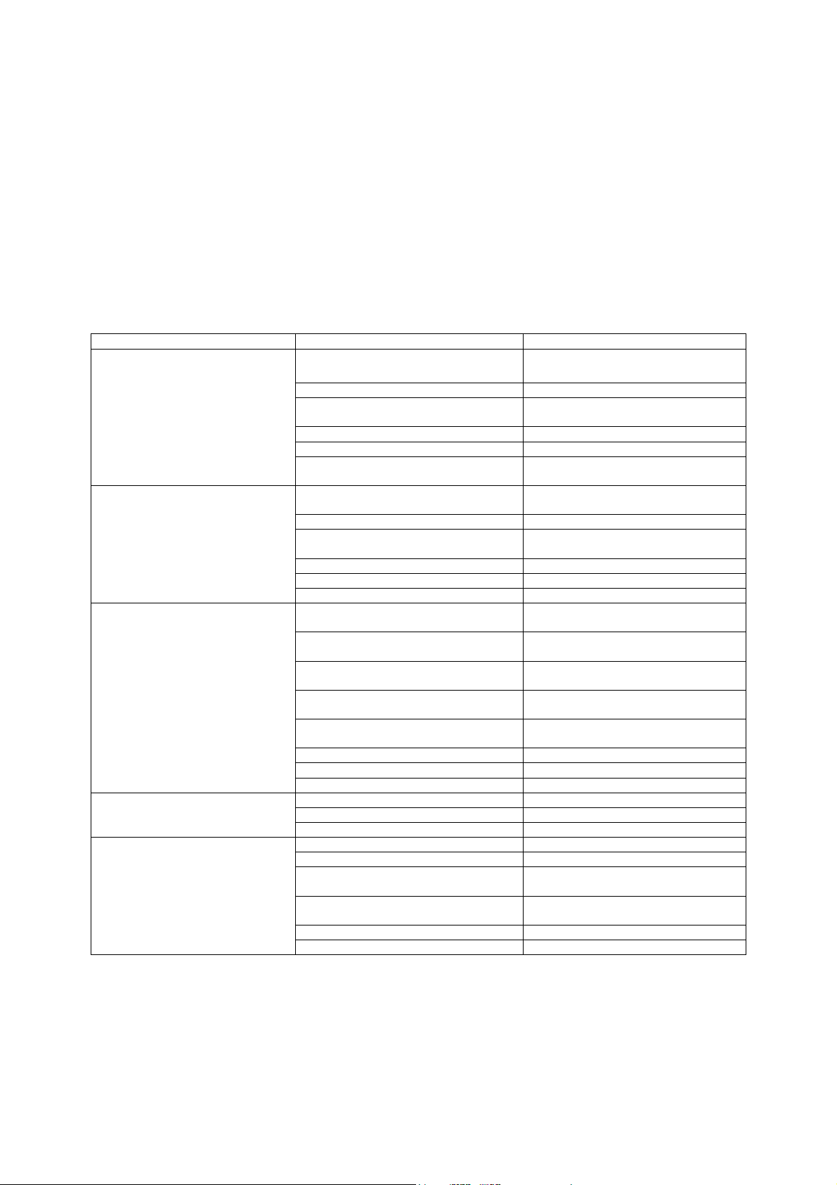
TROUBLESHOOTING
Motor starter overloaded
Reset starter and check amps
Overload in starter set too low
Set overload to motor FLA value
Supply grills or registers closed
Open and adjust
Duct static pressure lower than design
Reduce fan RPM
replacement
Belts too loose, worn, or oily
Inspect and replace if needed
The following tables list causes and corrective actions for possible problems with direct fired heater units.
Review these lists prior to consulting the manufacturer.
Airflow Troubleshooting Chart
Problem
Fan inoperative Blown fuse or open circuit breaker Replace fuse or reset circuit breaker
Motor overload Fan rotating in the wrong direction Be sure fan is rotating in the direction
Insufficient airflow Fan rotating in the wrong direction Be sure fan is rotating in the direction
Potential Cause
Disconnect switch in “OFF” position Turn to “ON” position
Motor wired incorrectly Check motor wiring against wiring
Broken fan belt Replace belt
Remote panel set to “OFF” position Set Remote Panel to “MANUAL” or
Fan speed is too high Reduce fan RPM
Motor wired incorrectly Check motor wiring against wiring
Motor HP too low Determine if HP is sufficient for job
Duct static pressure lower than design Reduce fan RPM
Poor outlet conditions There should be a straight, clear duct
Intake damper not fully open Inspect damper linkage and replace
Duct static pressure higher than
design
Blower speed too low Increase fan RPM. Do not overload
Corrective Action
and check amps
diagram located on fan motor
“AUTO” Position
shown on rotation label
diagram located on fan motor
shown on rotation label
at the outlet
damper motor if needed
Improve ductwork to eliminate or
reduce duct losses
motor
Excessive airflow Blower speed to high Reduce fan RPM
Excessive vibration and noise Misaligned pulleys Align pulleys
Dirty or clogged filters Clean and/or replace
Belt slippage Adjust belt tension
Filters not installed Install filters
Damaged or unbalanced wheel Replace wheel
Fan is operating in the unstable region
of the fan curve
Bearings need lubrication or
Fan speed is too high Reduce fan RPM
Refer to performance curve for fan
Lubricate or replace
26
Page 27
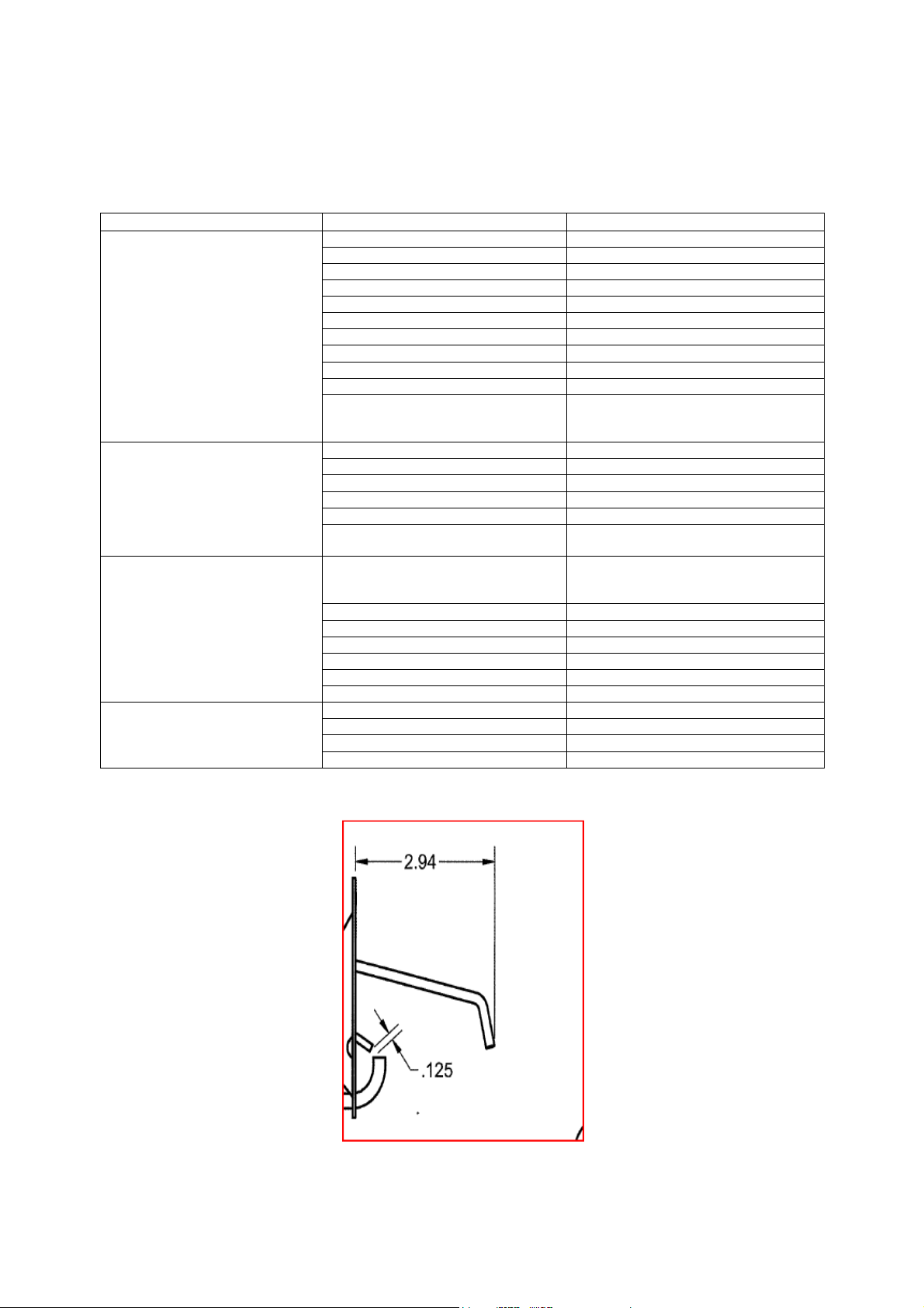
Burner Troubleshooting Chart
Dirt in pilot orifice
Clean orifice with compressed air.
Excessive drafts
Re-
direct draft away from unit.
Loose valve wiring
Check wiring to valve.
and main gas begins to flow
p
ilot gas tube with burner cement.
on size 4
-
5 heater).
Gas controls not wired properly
Check wiring.
Thermostat malfunction
Check/replace thermostat.
Thermostat setting too high
Decrease thermostat setting.
Thermostat wired incorrectly
Check thermostat wiring.
Proper Spark Gap
Problem
Pilot does not light/stay lit Main gas is off Open main gas valve.
Main burner does not light
(Pilot is lit)
Not enough heat Main gas pressure too low Increase main gas pressure – do not
Potential Cause
Air in gas line Purge gas line.
Gas pressure out of range Adjust to proper gas pressure.
Pilot valve is off Turn pilot valve on.
Leaking pilot orifice fitting Tighten pilot orifice.
Safety device has cut power Check limits and airflow switch.
Dirty flame sensor Clean flame sensor.
Remote panel in “Vent” mode Change to “Heat” mode.
No spark at igniter Check wiring, sensor, and ignition
Defective valve Replace combination valve.
Defective pilot sensor Replace pilot sensor.
Shut-off valve closed Open shut off valve.
Defective flame safety controller Replace flame safety controller.
Pilot fails as main gas valves open
Too much airflow Decrease airflow if possible.
Burner undersized Check design conditions.
Corrective Action
controller. Check spark gap as shown
below.
Plug the first burner port next to the
exceed 14 in. w.c. inlet pressure (5 psi.
Thermostat setting too low Increase thermostat setting.
Unit locked into low fire Check wiring.
Too much heat Defective modulating gas valve Check/replace modulating valve.
Unit locked into high fire Check wiring.
27
Page 28
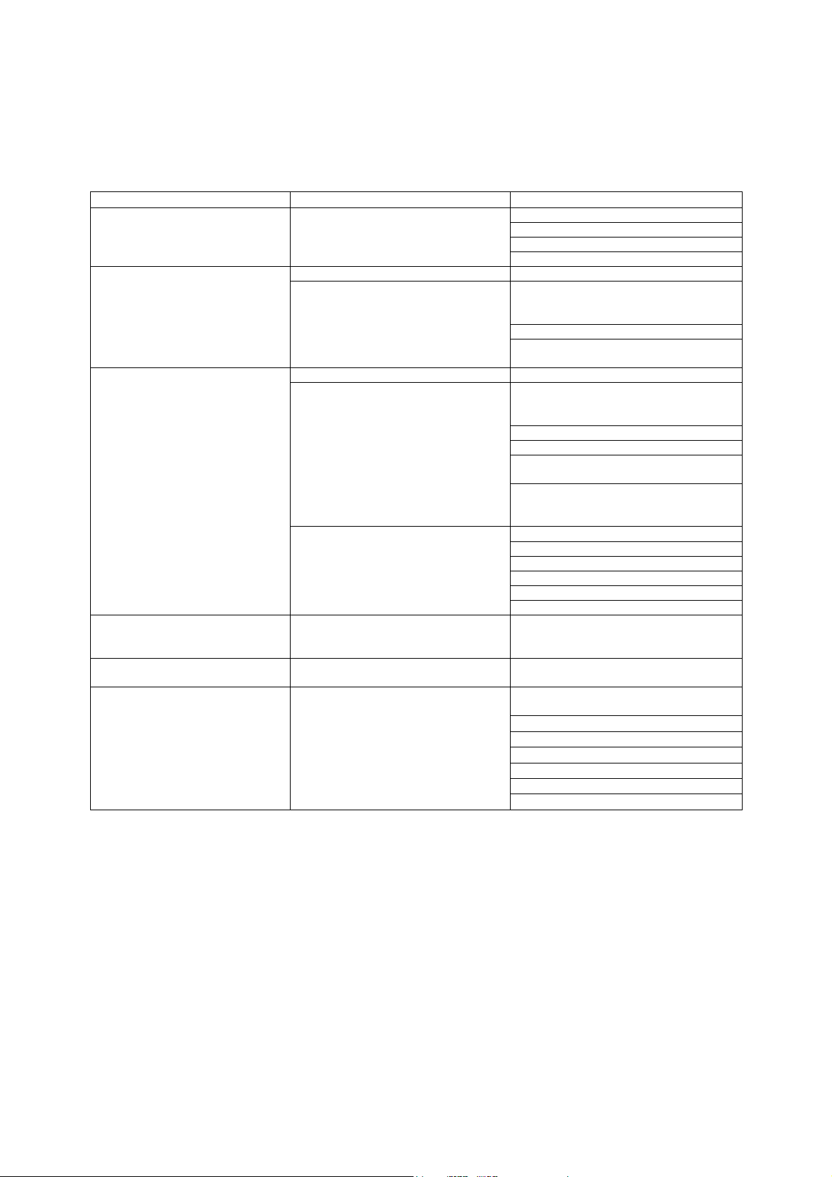
Remote Panel Troubleshooting Chart
Circuit breaker tripped
Heat/Vent switch in “VENT” position
tripped
satisfied
Excessive airflow
Problem with airflow tubing
(Unit sizes 1
-3)
Light Indication
No lights Power not available to Remote Panel Bad voltage to unit
POWER light only Proper unit Off Operation No problem
POWER light and
BLOWER ON light
Condition
No power to motor starter Manual/Off/Auto switch in “OFF”
Proper ventilation operation No problem
No power to flame safety controller Manual/Off/Auto switch in “OFF”
Improper airflow Insufficient airflow
Possible Cause
Main Disconnect in “OFF” position
Bad main transformer
position (3-position Remote Panels
only)
Improper damper function
Low Temperature Thermostat timed out
(option)
position (2-position Remote Panels
only)
Gas pressure switch Tripped (option)
High Temperature Limit Thermostat
Manual/Off/Auto Switch in “AUTO”
position and Intake Air Thermostat not
Bad airflow switch
Problem with air probes
POWER light and
BLOWER ON light and
BURNER ON light
CLOGGED FILTER light on
(optional)
FLAME FAILURE light on Flame safety alarm activated
Proper heating operation No problem
Filters clogged Filters dirty or need replacement
No flame detected during pilot
establishment period
Broken belt
Combination valve in “OFF” position
Stuck closed gas valve
No or low gas pressure
Bad spark electrode
Bad ignition transformer
Flames sensor malfunction
Clogged pilot orifices
28
Page 29
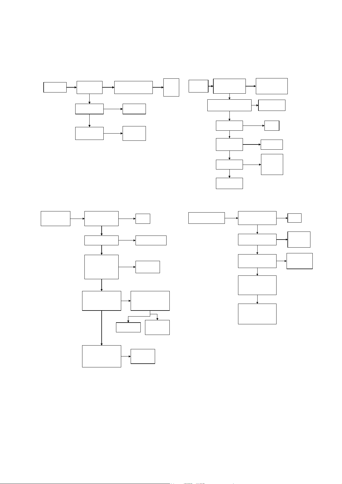
Troubleshooting Flowcharts
Nothing
Happens
Is Overload
tripped on
starter?
NO
Is Freeze-Stat
open?
NO
Is end switch on
Motorized
Damper closed?
Reset & measure FLA
YES
of motor. Is it higher
YES
NO
than rating?
Adjust or
Replace
Adjust or
Replace
actuator
YES
Adjust
or
change
Pulley
Blower runs
but there is
no heat
Is the air flow LED
on Flame Saftey
illuminated?
Is outside air cooler than
intake air thermostat
YES
setting?
YES
Is High Temp.
Limit Tripped?
NO
Is there a
Remote Panel
Installed?
YES
Is Remote set to
"Heat"
YES
Refer to Flame
Safety Guide
NO
YES
NO
NO
Adjust pulley to
achieve proper
NO
Check wiring
"Manual" and
"Heat" mode.
airflow.
Proper
economizer
operation
Reset
Set Remote
Panel to
Burner lights but
heater stays in
Low Fire
Is there voltage on
Terminal #17
Yes
Are all valves
powered and open?
Yes
With wires 3 & 4
removed from the
Maxitrol Amplifier, is
there 9.5K to 11K
Ohms between the
wires?
Yes
Remove Terminal #4
from the Maxitrol
Amplifier. Does the
heater go into High Fire?
Yes
With wires 1 & 2
removed from the
Maxitrol Amplifier, is
there 9.5K to 11K Ohms
between the wires?
No
Replace
FSC
No
Check valve wiring
or open valves
Replace
No
Discharge Air
Sensor
Is there a short or open
No
circuit in Modulating
Valve? Should be 45-55
Ohms (60-80 on MR212)
No
Replace
Amplifier
Replace the
No
Temperature
Selector
Yes
Replace
Modulating
Valve
Burner lights but heater
stays in High Fire
Is there a jumper between
terminals 2 & 3 on the
Maxitrol Amplifier?
Yes
Is there a short circuit in
the Remote Temperature
Selector or wiring?
No
Is there an open circuit in
the Discharge Air Sensor
or wiring?
No
Is Plunger in the
Modulating Valve jammed?
Inspect and clean. It
should operate freely in
the sleeve.
No
Foreign object holding
valve open. Remove
bottom plate and inspect
valve and seat. Clean or
replace valve.
No
Yes
Yes
Install
Jumper
Repair short or
replace
Temperature
Selector
Repair Circuit or
replace the
Discharge Air
Sensor
29
Page 30
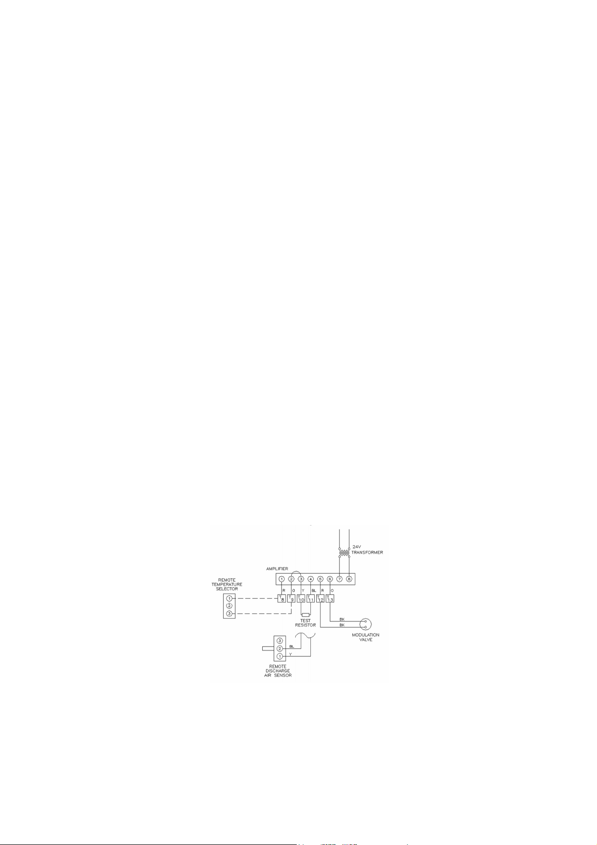
Maxitrol Preliminary Circuit Analysis
The basic Series 14 system consists of an amplifier, a discharge-air sensor and mixing tube, a remotetemperature selector, and a modulating valve or a modulator-regulator valve.
Series 14 Preliminary Wiring Testing Procedures:
• Disconnect the discharge-air sensor and replace with a 10,000-Ohm, 1/4-watt test resistor at
Terminals 3 & 4.
• Connect a dc-volt meter on the modulator-regulator or modulator-valve terminals.
• Set the temperature to 55° F. Voltage should read 0-V.
• Rotate dial to 90° F. Voltage should gradually increase to a minimum of 20-V.
• If these voltages are obtained, the valve function can now be checked out.
• In the event proper voltages are obtained, and the valve responds correctly to these voltages, the
problem could be in the wiring to the discharge-air sensor or the discharge-air sensor itself.
• If the proper voltages are not obtained when wired as shown above, the problem can be isolated to
the electronics.
After these preliminary tests are completed, remove the test resistor and reconnect the discharge air
sensor to Terminals 3 and 4 and continue checking system, following the Series 14 Troubleshooting
Steps.
The operation of the modulating-valve regarding voltage is as follows:
o 0 to 5-V The heater should be at bypass or low.
o 5 to 15-V The heater should respond to various input rates.
o 15-V and up The heater is at maximum input.
• If the voltage is obtained on the valve terminals, but the heater does not respond as described, the
problem can be isolated to the valve itself or to the gas-control manifold of the heater.
Series 14 System
30
Page 31

negative pressure.
inlet air restrictions.
Symptom
No Gas Flow Modulating valve improperly
Continuous low fire
(electronics problem)
Continuous low fire
(electronics OK)
Incorrect minimum fire Incorrect by-pass metering
Maxitrol Series 14 Troubleshooting
Possible Cause Field Test Remedy
installed
Short circuit or no voltage to
the amplifier
Open circuit in TD114 remote
temperature selector or wiring
Short circuit in TS114 remote
temperature circuit or wiring
Faulty amplifier
Open circuit in modulator coil
Plunger missing, jammed, or
improperly installed
valve adjustment
Excessive negative burner
pressure
Arrow on side of valve should
point in direction of gas flow
Check for 24-V at amplifier
terminals 7 & 8
Check wire connections
between amplifier terminals 1
and 2 and remote
temperature selector terminals
1 and 3
Follow test procedures as
outlined in the preliminary
testing section of this manual
Check Td114 for internal open
circuits. Maximum 11,500
ohms across terminals 1 and 3
with external wiring
disconnected. Measure
resistance across modulator
terminals with interconnecting
wires disconnected.
Inspect: Plunger should
operate freely in solenoid
sleeve.
Re-set low fire (see start-up
instructions)
Close main-gas supply and
measure manifold pressure
with blower opening. Reading
should be less than 1.5-in wc
Install properly
Prove power source
Tighten connections or
replace wiring
If modulating voltages
are obtained, check
TS114 if necessary. If
these items check out
and modulating voltages
are still not obtained,
amplifier may be
assumed defective.
Install replacement.
Replace modulator head
if not approximately 45
to 55 ohms for the M611
and M511 and 60 to 80
ohms for the MR212.
Clean or replace plunger
if necessary.
Adjust to proper low fire
If reading is greater than
1.5-in wc negative
pressure, check for
clogged filters or other
Continuous high fire
(electronics problem)
Short circuit in remote
temperature selector circuit
Open Circuit in the TS114
discharge air sensor circuit
Jumper not connected across
amplifier terminals 2 and 3
Inspect for shorts at or
between amplifier terminals 1
and 2 and at TD114 terminals
1 and 3.
Check TS114 for terminal
shorts, minimum 8,000 ohms
across terminals 1 and 3 with
external wiring disconnected.
Connect test resistor as
described in the preliminary
circuit test.
31
Correct wiring if a short
is present. Replace
TD114 if defective.
If modulating voltages
are obtained, check
TS114 circuit for shorts.
Replace TS114 if
necessary.
Correct if necessary.
Page 32

Symptom
Possible Cause
Field Test
Remedy
Continuous high fire
maintain an even flame
contain surges.
sensed.
(electronics OK)
Incorrect maximum
fire
Foreign object holding valve
open or plunger jammed
Inlet pressure too low
Incorrect outlet pressure
adjustment of pressure
regulator
Hunting
Inspect: plunger should be
smooth and clean, and
operate freely in the solenoid
valve.
Read pressure at inlet to
modulating valve using a
manometer with unit
operating at high fire.
Pressure should be equal to
the sum of the outlet pressure
setting plus pressure drop of
the valve.
Read manifold pressure using
manometer and compare with
recommendation of the heater
manufacturer.
Adjust sensitivity control
counter clockwise.
Clean or, if necessary,
replace plunger
Increase inlet pressure,
if possible.
If flame stabilizes, adjust
sensitivity control to
Erratic or pulsating
flame
Incorrect discharge air
temperature
Erratic air patterns or improper
TS114 location
TD114 wiring is run next to
high voltage switching circuits
causing induced voltages
Faulty amplifier or erratic
voltage supply
Incorrect wiring
Improper TS114 location
Connect test resistor as
described in the preliminary
circuit analysis section. Turn
TS114 selector dial so heater
goes though its entire
modulating range.
Temporarily remove TD114
from its remote locating and
reconnect at valve location.
Observe heater observation.
With test resistor connected
as described in the preliminary
tests, and TD114 locally
connected as described above,
turn TD114 selector dial
though entire modulating
range. Observe voltage
across modulator terminals.
Check installation according to
the diagram in the preliminary
circuit analysis section.
Sensed temperature does not
represent average discharge
air temperature.
If the flame is steady
thought-out the entire
modulating range, the
TS114 must be
relocated.
If smooth operation
results, isolate TD114
wiring from source of
induced voltage.
If erratic or unstable
voltages are obtained
throughout the
modulating range, the
amplifier may be
assumed defective.
Replace. If erratic
operation is noted only
over a small range, the
voltage source may
Correct wiring
Move TS114 to location
where average
representative
temperature can be
32
Page 33
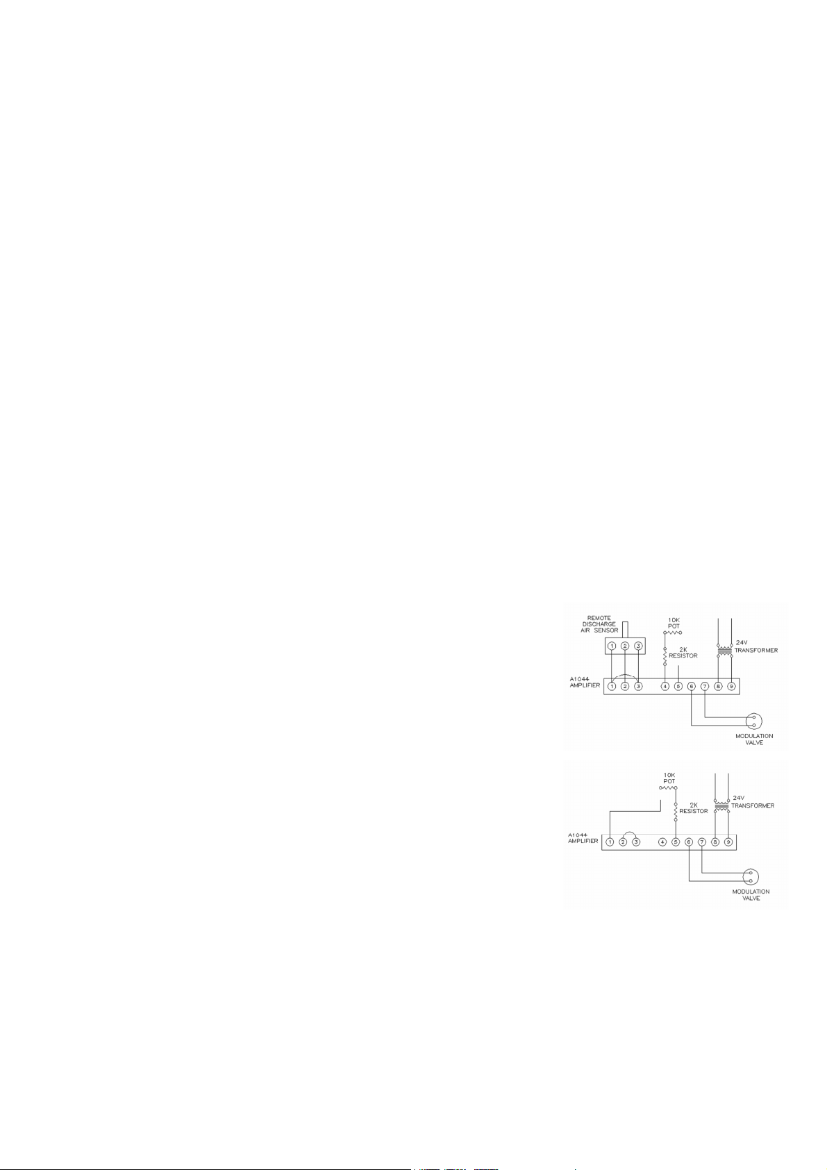
Maxitrol Preliminary Circuit Analysis Series 44 System
The basic Series 44 system consists of an amplifier, a discharge-air monitor with mixing tube, a
selectrastat, and a modulating valve or a modulator-regulator valve.
Series 44 Wiring for Preliminary Testing Procedures:
• Turn the test potentiometer to 2,000-Ohm minimum resistance. The dc voltage should read 0-V.
Slowly turn the test potentiometer to maximum resistance or 12,000-Ohms. The dc voltage
should gradually increase to at least 18-V.
• If proper voltages are observed, continue with the following test procedures.
• If proper voltages are not observed, the problem is identified with the amplifier, the 24-V ac power
supply, or the circuit connected to Terminals 6 and 7.
• Turn power OFF. Wire system as shown. Turn power back ON.
• Turn the test potentiometer to minimum resistance. The dc voltage should read 0-V. Slowly turn
the test potentiometer to maximum resistance. The dc voltage should gradually increase to at
least 18-V.
• If proper voltages are observed, continue with the following test procedures.
• If proper voltages are not observed, the problem is identified with the amplifier, the 24-V ac power
supply, or the circuit connected to Terminals 6 and 7.
• Observe burner flame and burner pressure as test potentiometer is turned through full range.
o 0 to 5-V The heater should be at bypass or low.
o 5 to 15-V The heater should respond to various input rates.
o 15-V and up The heater is at maximum input.
• If proper voltages are observed, continue procedures to check
operation of sensing and selecting components.
• If proper voltages are not observed, see checklist on the following
page to test the MR212 or M611 modulating valve and
connecting wiring.
• With proper voltages present and modulator responding correctly,
return to the wiring configuration as shown below, except have
the TS144 discharge-air monitor connected in place of the
jumper. Set minimum-temperature selector at least 10° F above
outdoor temperature. Set maximum-temperature selector at midrange. Heater is now under control of the discharge-air monitor.
• Turn test potentiometer to maximum resistance. Air temperature
should be at maximum-temperature setting. Turn test
potentiometer to minimum resistance. Delivered air temperature
should be at minimum temperature setting.
• If proper voltages are not observed, check calibration. See
checklist on the following page.
• If proper voltages are observed, the problem is identified with the space temperature sensing and
temperature selecting components and circuits.
• After these preliminary test procedures are completed, remove all test equipment and reconnect
components.
33
Page 34

Maxitrol Series 44 Troubleshooting
negative pressure.
inlet air restrictions.
.
+-
150 (TD2440)
Symptom Possible Cause Field Test Remedy
No gas flow Modulating valve installed
improperly
Continuous low fire
(electronics problem)
Continuous low fire
(electronics OK)
Incorrect minimum fire Incorrect by-pass metering
No voltage to amplifier
Short in modulator coil circuit
Short in TS144 circuit
Defective amplifier
Open in modulator coil circuit
Plunger missing, jammed or
improperly installed
valve adjustment
Excessive negative burner
pressure
Arrow in side of valve should
point in direction of gas flow.
Check for 24-v ac at amplifier
terminals 8 and 9
Remove wires connected to
amplifier terminals 6 and 7;
measure resistance
MR212: 60 – 80 ohms
M611 & M511: 45 to 55 ohms
Remove wires connected to
amplifier terminals 1, 2, and
3. Measure resistance across
wires 1 and 3, then across 2
and 3. Meter should read
greater than 2500 ohms.
Follow procedures in the
preliminary circuit analysis
section
Remove wires connected to
amplifier terminals 6 and 7
measure resistance
MR212: 60 – 80 ohms
M611 & M511: 45 to 55 ohms
Inspect: plunger should
operate freely in solenoid
sleeve.
Re-set low fire (see start-up
instructions)
Close main-gas supply and
measure manifold pressure
with blower opening. Reading
should be less than 1.5-in wc
Install properly
Provide 24-v ac to
amplifier
If proper resistance
values are not observed;
replace modulator head
or repair wiring.
If readings are incorrect,
replace the TS114 or
repair wiring.
After following the
preliminary circuit
analysis test without
satisfactory results, the
amplifier can be
assumed defective.
Install replacement.
If proper resistance
values are not observed,
replace modulator head
or repair wiring
Clean or replace plunger
if necessary
Adjust to proper low fire
If reading is greater than
1.5-in wc negative
pressure, check for
clogged filters or other
Continuous minimum
discharge temperature
Defective amplifier
Short in T244 or TS244/TD244
circuit
Refer to the preliminary circuit
analysis section
Remove wires to amplifier
terminals 4 and 5. Set T244
or TD244 to maximum setting
Measure resistance across
wires. Meter should read
6000 ohms +- 1000 ohms. If
TS244/TD244 are used, meter
should read 4500 ohms +1000 (TS244) and 2100 ohms
34
If amplifier is proven
defective, install
replacement
If reading is incorrect,
replace T244,
TS244/TD244 or repair
wiring
Page 35

Symptom
Possible Cause
Field Test
Remedy
Incorrect minimum or
this manual
than 2500 ohms
.
maximum discharge
air temperature
Improper TS144 location
Incorrect discharge air
temperature control calibration
Compare sensed temperature
at TS144 with average
discharge air temperature
Refer to the preliminary circuit
analysis section
Move TS144 to location
where average
temperature can be
sensed
If proper temperatures
are not observed, refer
to control calibration of
Continuous high fire
(electronics problem)
Continuous high fire
(electronics OK)
Incorrect high fire Inlet pressure too low
Continuous maximum
discharge air
temperature
Open in TS144 circuit
Foreign material holding valve
open
Plunger jammed
Incorrect outlet pressure
adjustment
Defective amplifier
Open in T244 or TS244/TD244
Incorrect space temperature
control calibration
Remove wires to amplifier
terminals 1, 2, and 3.
Measure resistance between
terminals 1 and 3, then
between terminals 2 and 3.
Meter should read greater
Remove bottom plate and
inspect valve and seat
Inspect: plunger should be
smooth and clean, and
operate freely in solenoid
valve
With heater operating at full
fire, take pressure reading at
inlet to modulation valve.
Pressure should meet or
exceed the units minimum gas
pressure
Read outlet pressure using a
manometer and compare with
recommendation of unit
capacities
Refer to the preliminary circuit
analysis section
Remove wires to amplifier
terminals 4 and 5. Set T244
or TD244 to maximum setting
Measure resistance across
wires. Meter should read
6000 ohms +- 1000 ohms. If
TS244/TD244 are used, meter
should read 4500 ohms +1000 (TS244) and 2100 ohms
+- 150 (TD2440)
See control calibration section
of this manual
If readings are incorrect,
replace TS114 or repair
wiring
Clean and replace valve
and seat. Replace if
necessary
Clean, or if necessary,
replace plunger
Increase inlet pressure if
possible, or change to a
larger modulation valve.
Contact manufacturer for
increasing valve size.
See control calibration of
this manual
Replace amplifier if
defective
If reading is incorrect,
replace T244,
TS244/TD244 or repair
wiring
If proper action is
obtained, see calibration
section of this manual
35
Page 36
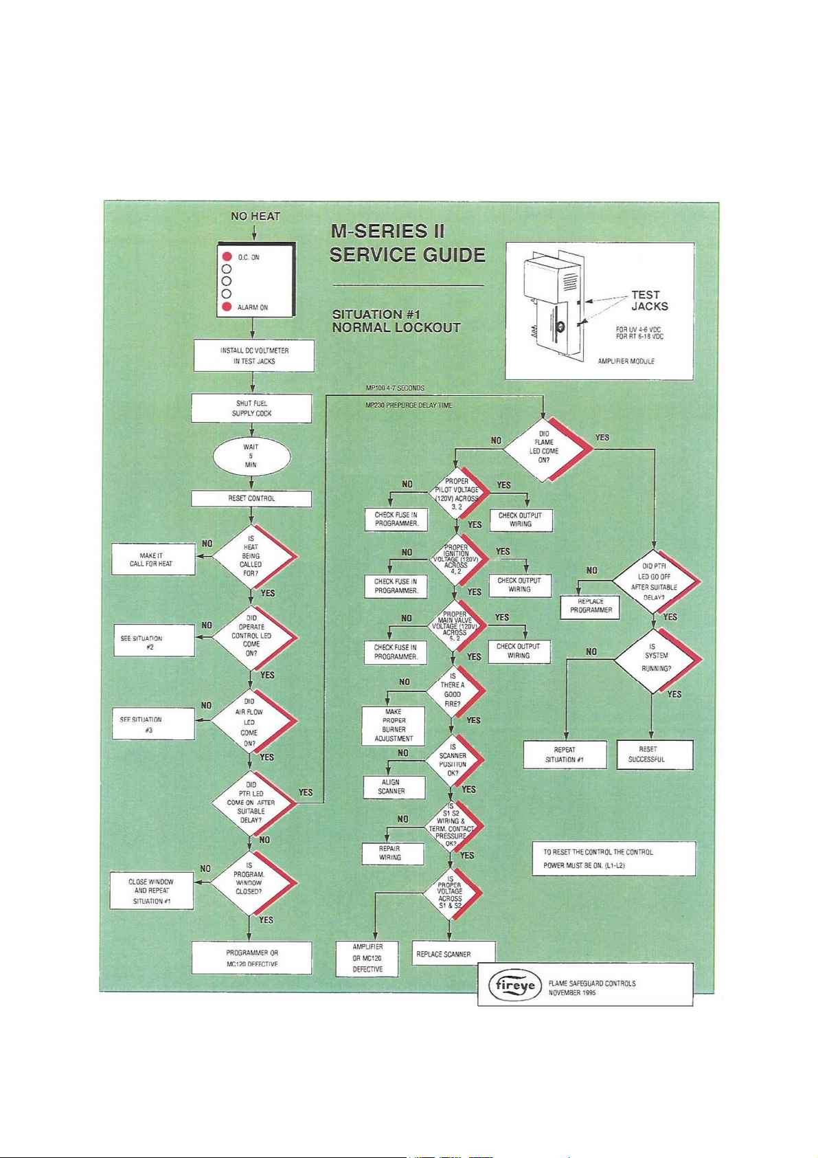
Flame Safety Service Guide
(Airflow LED may or may not be illuminated)
36
Page 37
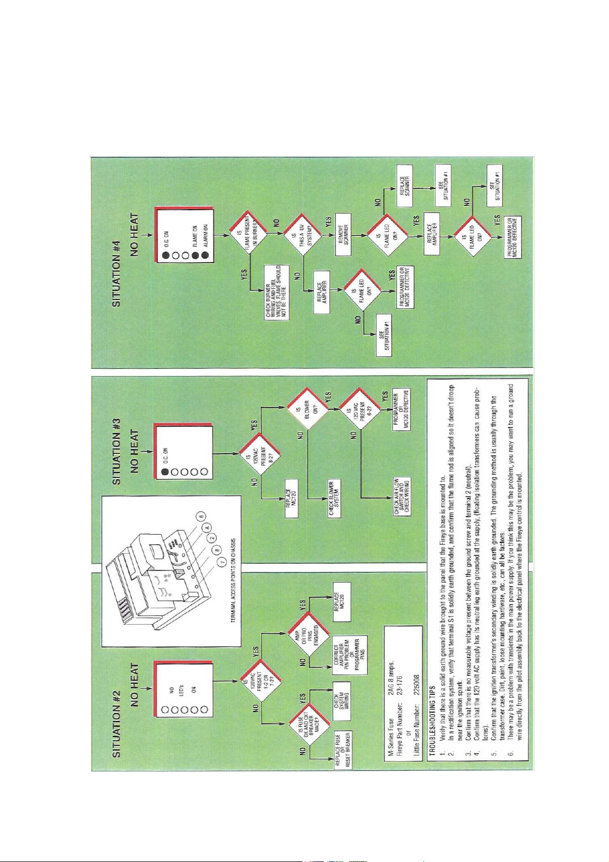
Flame Safety Service Guide (continued)
(Airflow LED may or may not be illuminated)
37
Page 38

MAINTENANCE
To guarantee trouble free operation of this heater, the manufacturer suggests following these guidelines.
Most problems associated with fan failures are directly related to poor service and maintenance.
DO NOT ATTEMPT MAINTENANCE ON THE HEATER UNTIL THE ELECTRICAL SUPPLY HAS BEEN
COMPLETELY DISCONNECTED AND THE MAIN GAS SUPPLY VALVE HAS BEEN TURNED OFF.
General Maintenance
1. Fan inlet and approaches to ventilator should be kept clean and free of any obstructions.
2. Motors are normally permanently lubricated. Check bearings periodically. If they have grease
fittings, lubricate each season. Use caution when lubricating bearings. Wipe the fittings clean.
The unit should be rotated by hand while lubricating. Caution: Use care when touching the
exterior of an operating motor. Motors normally run hot and may be hot enough to be
painful or cause injury.
3. Before starting a unit after maintenance checks, check all fasteners for tightness.
4. Blowers require very little attention when moving clean air. Occasionally oil and dust may
accumulate, causing imbalance. If the fan is installed in a corrosive or dirty atmosphere,
periodically inspect and clean the wheel, inlet and other moving parts to ensure smooth and safe
operation.
WARNING!!
Re-Setting Of The Unit
If the flame safety control is locked out (alarm
light on), reset the unit by:
1. Turn OFF power to the unit.
2. Turn power to the unit back ON.
Emergency shutdown of unit
To shut down the unit in the event of an
emergency do the following:
1. Turn power OFF to the unit from main
building disconnect.
2. Turn the external disconnect switch to the
OFF position.
3. Close the inlet gas valve located on the
heater.
Lubricating Blower Bearings
Blower bearings require little lubrication. A general rule is one half pump from a grease gun for ½” to 1
7/16” shaft diameters and one pump for 1 11/16” and large diameter shafts for every 1500 to 3000 hours
of operation. A lithium based grease should be used. Bearings should be rotated as they are lubricated
to evenly distribute the grease, either by hand or via extended grease lines. Do not attempt to grease
bearings from inside the enclosure while the motor is energized.
Prolonged shutdown of the unit
For prolonged shutdown the following steps
should be done:
1. Turn the external disconnect switch to the
OFF position.
2. CLOSE the inlet gas valve located on the
heater.
To re-start the unit the following steps
should be done:
1. Turn the external disconnect switch to the
ON position.
2. OPEN the inlet gas valve located on the
heater.
38
Page 39

Orifice
Drill Size
Gas Port
31
2 Weeks after Start-Up
1. Belt tension should be checked after the first two weeks of fan operation. Belts tend to stretch
and settle into pulleys after an initial start-up sequence. Do not tighten the belts by changing
the setting of the motor pulley. This will change the fan speed and may damage the motor.
To re-tension belts, turn disconnect OFF. Loosen the fasteners that hold the blower scroll plate
to the blower. Rotate the motor to the left or right to adjust the belt tension. Belt tension should
be adjusted to allow 1/64” of deflection per inch of belt span. Exercise extreme care when
adjusting V-belts as not to misalign pulleys. Any misalignment will cause a sharp reduction in belt
life and produce squeaky noises. Over-tightening will cause excessive belt and bearing wear as
well as noise. Too little tension will cause slippage at startup and uneven wear. Whenever belts
are removed or installed, never force belts over pulleys without loosening motor first to
relieve belt tension. Use the same type belt as originally supplied by the manufacturer when
replacements are needed. On units shipped with double groove pulleys, matched belts should
always be used.
2. Before restarting a unit after maintenance checks, all fasteners on blower housings, bearings,
motors and sheaves should be checked for tightness.
Every 3 months
1. Belt tension should be checked quarterly. See instructions in the previous maintenance section.
Over-tightening will cause excessive bearing wear and noise. Too little tension will cause
slippage at startup and uneven wear.
2. Filters need to be cleaned and/or replaced quarterly, and more often in severe conditions.
Washable filters can be washed in warm soapy water. When re-installing filters, be sure to install
with the airflow in the correct direction as indicated on the filter.
Yearly
1. Inspect bearings for wear and deterioration. Replace if necessary.
2. Inspect belt wear and replace torn or worn belts.
3. Inspect bolts and set screws for tightness. Tighten as necessary.
4. Inspect motor for cleanliness. Clean exterior surfaces only. Remove dust and
grease from the motor housing to ensure proper motor cooling. Remove dirt and
grease from the wheel and housing to prevent imbalance and damage.
5. Check for gas leaks and repair if present.
6. Clean flame sensor by rubbing with steel wool to remove any rust build-up,
7. Clean burner with a wire brush and insure burner ports are free of debris. Then wipe the burner
with a clean rag.
Burner Orifice
Air Port 43
39
Drill Size
Page 40
START-UP CHECKLIST
JOB INFORMATION
TECHNICIA
N INFORMATION
Name Plate and Unit Information
Field Measured
Information
High Fire Manifold Gas Pressure
in.
w.c.
Space
Correct
WARNING!!
-The Start-Up must be completed after all field wiring and air balancing has been completed
-The Start-Up must be completed by a qualified HVAC technician
-The Start-Up Check list must be faxed into the Service Department to validate the product warranty
Job Name Service Company
Address Address
City City
State State
Zip Zip
Phone Number Phone Number
Fax Number Fax Number
Contact Contact
Purchase Date Start-Up Date
Refer to the start-up procedure in this manual to complete this section.
Model Number
Serial Number
Motor Volts
Motor Hertz
Motor Phase
Motor FLA
Motor HP
Blower Pulley
Motor Pulley
Belt Number
Gas Type
Min. Btu/Hr
Max. Btu/Hr
*
If measured amps exceed the FLA rating on the nameplate, fan RPM must be reduced to decrease the
measured amps below the nameplate FLA rating.
**Low speed readings used on variable air volume units.
Motor Voltage
Motor Amperage*
Low Speed RPM **
High Speed RPM
Low Speed Differential Pressure ** in. w.c.
High Speed Differential Pressure in. w.c.
Pilot Flame Signal VDC
Low Fire Flame Signal VDC
High Fire Flame Signal VDC
Gas Type Natural
High Fire Inlet Gas Pressure in. w.c.
Low Fire Manifold Gas Pressure in. w.c.
Temperature Control Discharge
Airflow Direction
Propane
Incorrect
Factory Service Department
Phone: 866-784-6900
Fax: 919-554-9374
Revision 12 – 11.19.2013
 Loading...