

FloAire Motor Replacement For Direct Drive Fans User Manual
1. Make sure that the power is disconnected from the fan.
on
Motor Replacement For Direct Drive Fans (Motors With Lugs)
1. Make sure that the power is disconnected from the fan.
on
Instructions:
2. Remove fan hood by releasing the hood retaining clips.
2. Remove fan hood by releasing the hood retaining clips.
3. Disconnect the motor wire harness by unsnapping the quick release
3. Disconnect the motor wire harness by unsnapping the quick release
connection.
connection.
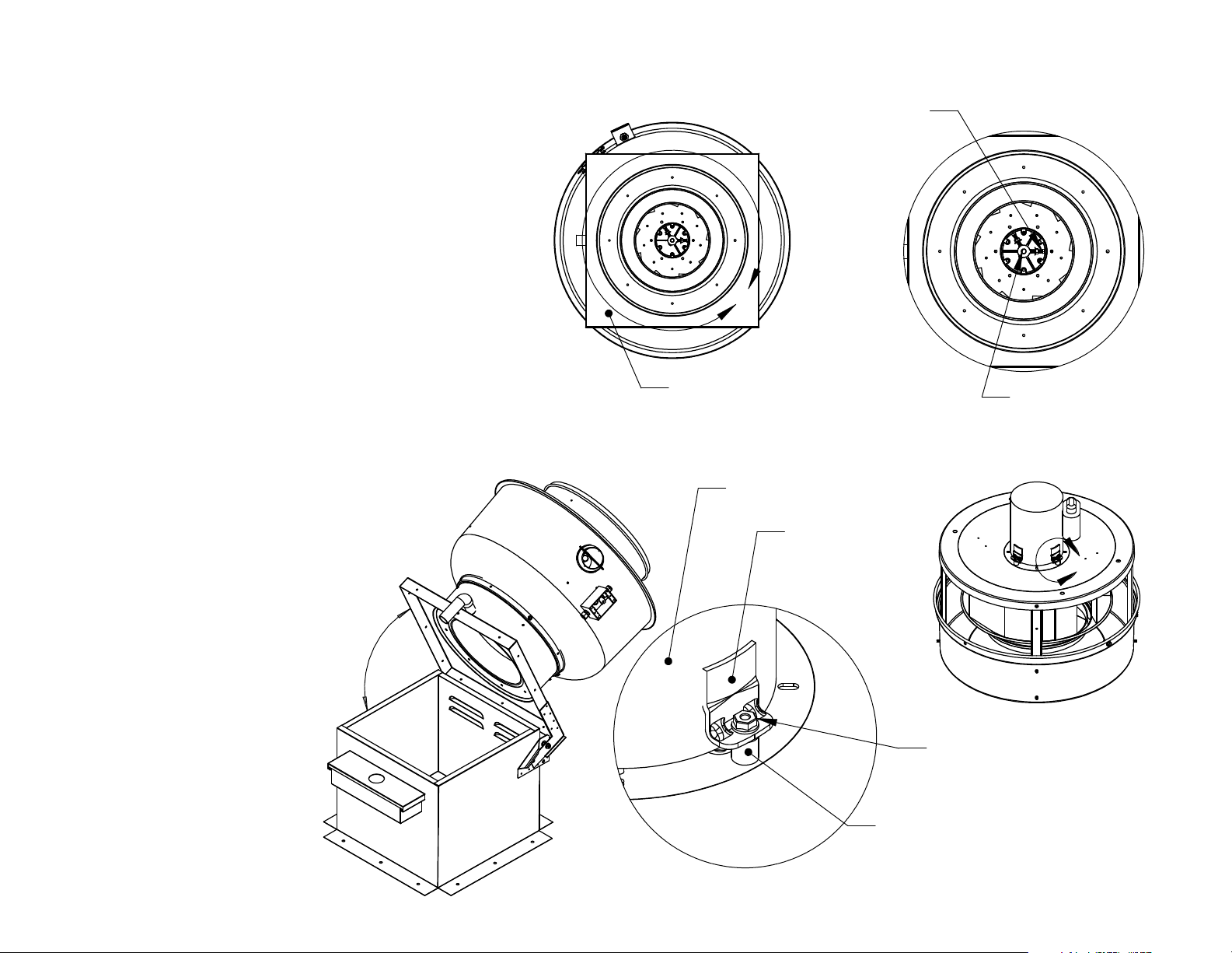
4. Tilt the fan back on hinged base. This will allow access to the set screws
4. Tilt the fan back on hinged base. This will allow access to the set screws
that hold the wheel onto the motor.
that hold the wheel onto the motor.
5. The motor shaft has been designed with two flat areas. This allows the set
5. The motor shaft has been designed with two flat areas. This allows the set
screws to secure the motor, and also prevent the motor shaft from getting
screws to secure the motor, and also prevent the motor shaft from getting
stuck during removal from the fan. See detail AA.
stuck during removal from the fan. See detail AA.
6. The nuts that hold the set screws in place must be loosened first in order to
6. The nuts that hold the set screws in place must be loosened first in order to
loosen the set screws.
loosen the set screws.
7. Loosen set screws.
7. Loosen set screws.
8. Return the fan to its vertical position. (Non-Hinged)
8. Return the fan to its vertical position. (Non-Hinged)
9. Remove the nuts that secure the motor to the vibration isolators. See detail
9. Remove the nuts that secure the motor to the vibration isolators. See detail
BB. (3/8 OD Nut, 10-32 Thread).
BB. (3/8 OD Nut, 10-32 Thread).
10. Remove the motor.
10. Remove the motor.
11. Mount the new motor. Secure the motor to vibration isolators with 10-32
11. Mount the new motor. Secure the motor to vibration isolators with 10-32
lock nuts. Lock nuts must be serrated or have star washer. *DO NOT USE
lock nuts. Lock nuts must be serrated or have star washer. *DO NOT USE
NYLON LOCK NUTS*
NYLON LOCK NUTS*
12. When inserting the new motor the bottom face of the hub should be flush
12. When inserting the new motor the bottom face of the hub should be flush
with the end of the shaft. Make sure that the set screws are over the flats
with the end of the shaft. Make sure that the set screws are over the flats
the motor shaft and lock tight is used before tightening the set screws.
the motor shaft and lock tight is used before tightening the set screws.
Torque set screws to 156 in-lbs. Remember to tighten the nuts as this will
Torque set screws to 156 in-lbs. Remember to tighten the nuts as this will
stop the set screws from backing out.
stop the set screws from backing out.
13. Make sure that the wheel spins freely and is centered over the inlet.
13. Make sure that the wheel spins freely and is centered over the inlet.
14. Reconnect the motor wire harness by snapping the quick release
14. Reconnect the motor wire harness by snapping the quick release
connections together.
connections together.
15. Fan hood should be put on the unit, make sure the hood retaining clips are
15. Fan hood should be put on the unit, make sure the hood retaining clips are
snapped shut.
snapped shut.
16. Reconnect the power and test run unit.
16. Reconnect the power and test run unit.
Detail A
AA
Base
Bottom View.
Motor.
Square Head
Set Screws &
Lock Nuts. DETAIL AA
Mounting
Lug.
Detail B
Direct Drive
Motor Shaft
With Double
Flat.
BB
Rev. 1 09/21/2010
DETAIL BB
SCALE 1 : 2
Nut With Tooth Washer
10-32 (3/8 OD x 1/8 HT)
Part # 90675A195.
S11 Isolator - DU/DR25,30 & 33.
S11D70 Isolator - DU/DR50,75 & 85.
DO NOT USE ISOLATORS WITH WALL
MOUNT FAN APPLICATIONS.
 Loading...