

Page 1
FOR YOUR SAFETY
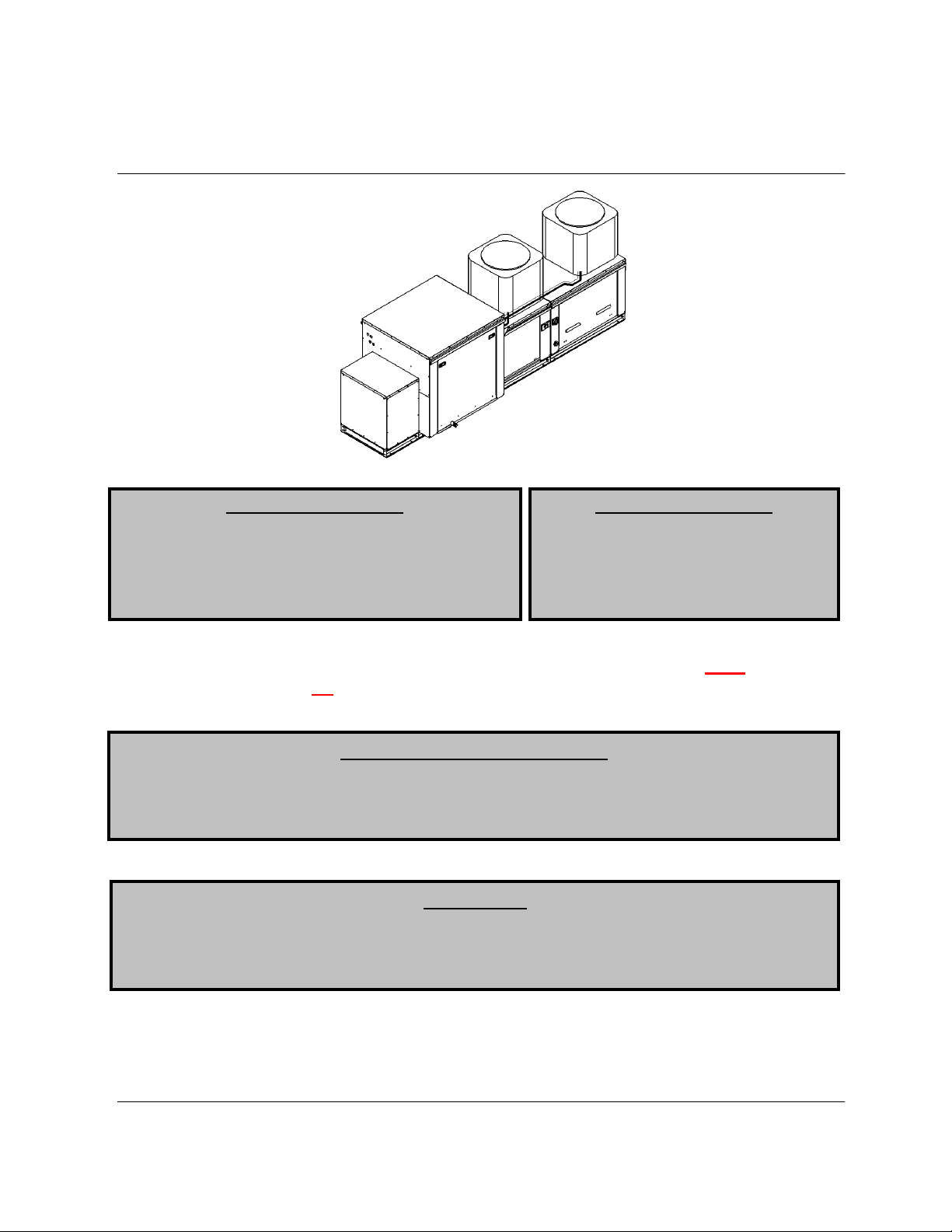
Modular Packaged Unit
Installation, Operation and Maintenance Manual
Modular Packaged Cooling Unit
Save these instructions
RECEIVING AND INSPECTION
WARNING!!
FOR YOUR SAFETY
The use and storage of gasoline or other flammable
vapors and liquids in open containers in the vicinity
of this appliance is hazardous.
If you smell gas:
1. Open windows.
2. Do not touch electrical switches.
3. Extinguish any open flames.
4. Immediately call your gas supplier.
Warning!!
while hoisting this unit. All lifting lugs must be utilized while hoisting. Manufacturer is
not liable for any damage or injuries resulting from failure to do so.
Upon receiving unit, check for any interior and exterior damage, and if found, report it
immediately to the carrier. Also check that all accessory items are accounted for and are
damage free. Turn the blower wheel by hand to verify free rotation and check the damper (if
supplied) for free operation.
Improper installation, adjustment, alteration, service or maintenance can cause property
damage, injury or death. Read the installation, operating and maintenance instructions
thoroughly before installing or servicing this equipment. ALWAYS disconnect power and gas
prior to working on heater.
Spreader Bar with length matching that of this entire unit Must be used
. This document is the property of the owner of this equipment and is
required for future maintenance. Leave this document with the owner when installation or
service is complete.
July 2014 Rev. 12
Page 2

TABLE OF CONTENTS
WARRANTY .................................................................................................................................................. 3
INSTALLATION ............................................................................................................................................. 4
Mechanical ................................................................................................................................................ 4
Site Preparation .................................................................................................................................... 4
Assembly .............................................................................................................................................. 4
Curb and Ductwork ............................................................................................................................... 4
Optional Moisture Eliminator Panel ...................................................................................................... 5
Typical Roof Mount Installation ............................................................................................................ 6
Typical Roof Mount Installation with Exhaust Fan ............................................................................... 6
Plumbing Connections ......................................................................................................................... 7
Typical Cooling Coil Drain Trap ............................................................................................................ 7
Gas ........................................................................................................................................................... 7
Electrical ................................................................................................................................................... 7
Copper Wire Ampacity ......................................................................................................................... 8
MUA/Condenser Fan to Building Wiring Connection ........................................................................... 9
OPERATION ............................................................................................................................................... 10
Start Up ................................................................................................................................................... 10
Special Tools Required ...................................................................................................................... 10
Start Up Procedure ............................................................................................................................. 10
Checking the Refrigerant Charge ....................................................................................................... 11
Superheat and Adjusting TXVs .......................................................................................................... 12
Checking Heating Mode for Units with Heat Pumps .......................................................................... 13
Sequence of Operation-Cooling with Direct, Indirect, or Electric Heat ................................................... 14
Sequence of Operation-Reheat .......................................................................................................... 15
Sequence of Operation-Liquid Bypass ............................................................................................... 15
Sequence of Operation-Cooling Only or Heat Pump.............................................................................. 15
Board Menu ............................................................................................................................................ 18
Troubleshooting Chart ............................................................................................................................ 20
MAINTENANCE .......................................................................................................................................... 21
General Maintenance ............................................................................................................................. 21
2 weeks after startup .............................................................................................................................. 21
Every 3 months ....................................................................................................................................... 21
Yearly ...................................................................................................................................................... 22
Start-Up and Maintenance Documentation ............................................................................................ 23
Job Information ................................................................................................................................... 23
Unit Information .................................................................................................................................. 23
Maintenance Record .......................................................................................................................... 24
Factory Service Department ............................................................................................................... 24
Page 3

WARRANTY
This equipment is warranted to be free from defects in materials and workmanship, under normal use and
service, for a period of 12 months from date of shipment. This warranty shall not apply if:
1. The equipment is not installed by a qualified installer per the MANUFACTURER’S installation
instructions shipped with the product,
2. The equipment is not installed in accordance with federal, state and local codes and regulations,
3. The equipment is misused or neglected,
4. The equipment is not operated within its published capacity,
5. The invoice is not paid within the terms of the sales agreement.
The MANUFACTURER shall not be liable for incidental and consequential losses and damages
potentially attributable to malfunctioning equipment. Should any part of the equipment prove to be
defective in material or workmanship within the 12-month warranty period, upon examination by the
MANUFACTURER, such part will be repaired or replaced by MANUFACTURER at no charge. The
BUYER shall pay all labor costs incurred in connection with such repair or replacement. Equipment shall
not be returned without MANUFACTURER’S prior authorization and all returned equipment shall be
shipped by the BUYER, freight prepaid to a destination determined by the MANUFACTURER.
3
Page 4
INSTALLATION
CLEARANCES
It is imperative that this unit is installed and operated with the designed airflow, gas, and electrical supply
in accordance with this manual. If there are any questions about any items, please call the service
department at 1-866-784-6900 for warranty and technical support issues.
Mechanical
WARNING: DO NOT RAISE VENTILATOR BY THE INTAKE HOOD, BLOWER OR
MOTOR SHAFT, OR BEARINGS – USE ALL LIFTING LUGS PROVIDED WITH A
SPREADER BAR OR SLINGS UNDER THE UNIT – USE CARE NOT TO DAMAGE
EXPOSED REFRIGERATIION LINES.
Site Preparation
1. Provide clearance around installation site to safely rig and lift
equipment into its final position. Supports must adequately
support equipment. Refer to manufacturer’s estimated weights.
2. Consider general service and installation space when locating
unit.
3. Locate unit close to the space it will serve to reduce long, twisted
duct runs.
4. Do not allow air intake to face prevailing winds. Support unit
above ground or at roof level high enough to prevent precipitation
from being drawn into its inlet. The inlet must also be located at
least 10 feet away from any exhaust vents. The unit inlet shall be
located in accordance with the applicable building code provisions
for ventilation air.
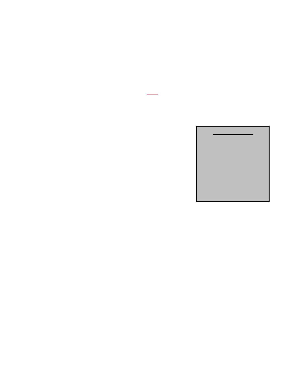
The top, back and front
surfaces of this unit may
not be installed less than 6”
from combustible materials.
The base may be installed
on combustible surfaces.
Allow 24” minimum service
clearance on both sides of
this unit. Do not enclose
top of condensers blocking
airflow.
Assembly
Intakes and curbs are shipped unassembled. Upon unit arrival, follow the following procedure to
assemble the intake to the heater:
1. Apply silicone or weatherproof gasket on the backside of the flanges of the intake hood or v-bank
intake.
2. Screw the flanges of the intake hood or v-bank to the unit with the supplied sheet metal screws.
If the unit is a modular unit with a v-bank or evaporative cooler section, the v-bank or evaporative
cooler will bolt to the main unit with the bolts provided. Place caulk on the outside of the screws
to prevent water leaks.
Curb and Ductwork
This fan was specified for a specific CFM and static pressure. The ductwork attached to this unit will
significantly affect the airflow performance. Flexible ductwork and square elbows should not be used.
Also, transitions and turns in ductwork near the fan outlet will cause system effect and will drastically
increase the static pressure and reduce airflow. Follow SMACNA guides and recommendations for
the remaining duct run. Fans designed for rooftop installation should be installed on a prefabricated or
factory built roof curb. Follow curb manufacturer’s instructions for proper curb installation. The unit
should be installed on a curb and/or rail elevated not less than 20” above any surface. Be sure duct
connection and fan outlet are properly aligned and sealed. Secure fan to curb through vertical portion of
the ventilator base assembly flange using a minimum of eight (8) lug screws, anchor bolts or other
suitable fasteners (not furnished). Shims may be required depending upon curb installation and roofing
material. Check all fasteners for tightness. The diagrams below show different mechanical installation
configurations.
4
Page 5

Optional Moisture Eliminator Panel
If the unit is equipped with an optional moisture eliminator panel, the maximum face velocity of the coil
may be increased to 650 FPM. Moisture eliminator panels require minimal maintenance. Visual
inspection is recommended periodically. Scale or clogging will impair performance. If scale or clogging
occurs, remove the panel and flush with steam or water. Flushing should not have sufficient force to
dislodge the media from the panel. Scale removal may require a vinegar or detergent application
followed by rinsing.
5
Page 6
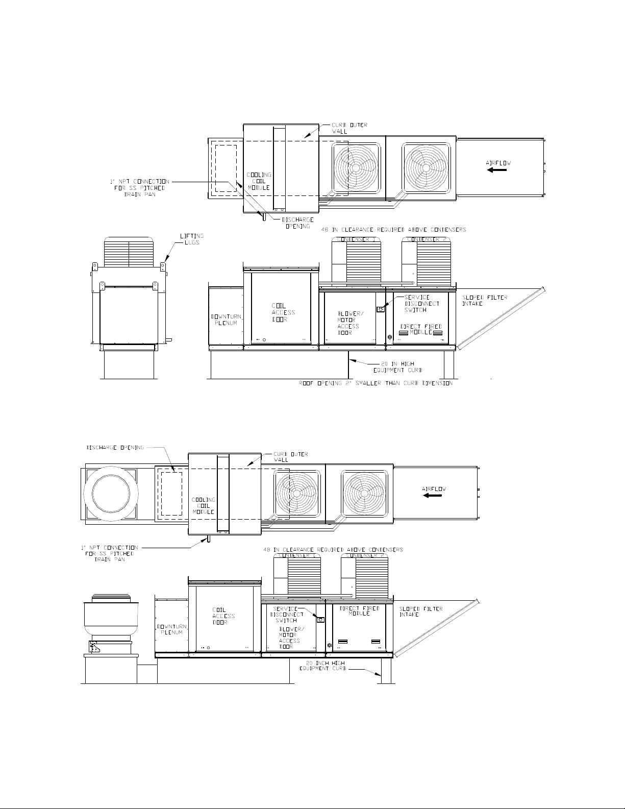
Typical Roof Mount Installation
Typical Roof Mount Installation with Exhaust Fan
6
Page 7
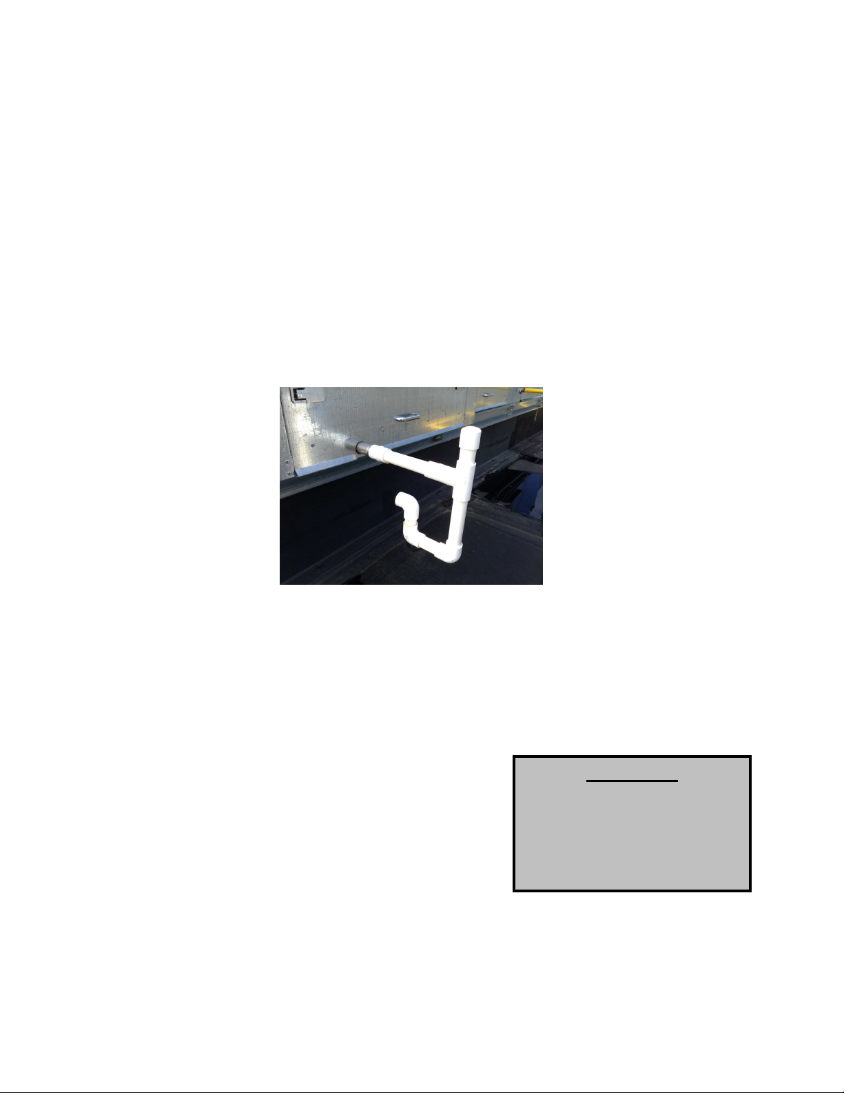
Plumbing Connections
WARNING!!
There is one field plumbing connection required for proper DX coil operation. This is the drain pan
located under the DX coil. Depending on the size of the unit, the coil can generate 5 gallons of water per
hour. It is imperative that the plumbing be sized accordingly. Also, it’s recommended that all plumbing
connections be sealed with Teflon tape or pipe dope.
Only 1” diameter PVC Pipe and low profile couplings should be used. Additionally, the top horizontal
length on the P-Trap should be a minimum of 12”. No unions should be used. Add a clean out as shown
in the picture below.
The P-Trap drain should be attached to the end of the drain pipe on the side of the unit. The trap is
important for two reasons. First, it can be piped to drain in the most convenient area. Second, it keeps
air from being drawn through the drain hole in the side of the pan, impeding drainage.
Typical Cooling Coil Drain Trap
Gas
Refer to the Make-up air (MUA) manual that shipped with this unit for gas installation details.
Electrical
Before connecting power to this unit, read and understand the
entire section of this document. As-built wiring diagrams are
furnished with each fan by the factory and are attached to the
door of the unit.
Electrical wiring and connections should be done in accordance
with local ordinances and the National Electric Code,
ANSI/NFPA70. Be sure the voltage and phase of the power
supply and the wire amperage capacity is in accordance with the
motor nameplate. For additional safety information refer to AMCA publication 410-96, Recommended
Safety Practices for Users and Installers of Industrial and Commercial Fans.
Disconnect power before
installing or servicing fan. High
voltage electrical input is
needed for this equipment. This
work should be performed by a
qualified electrician.
7
Page 8
1. Always disconnect power before working on or near
this unit. Lock and tag the disconnect switch or breaker
to prevent accidental power up.
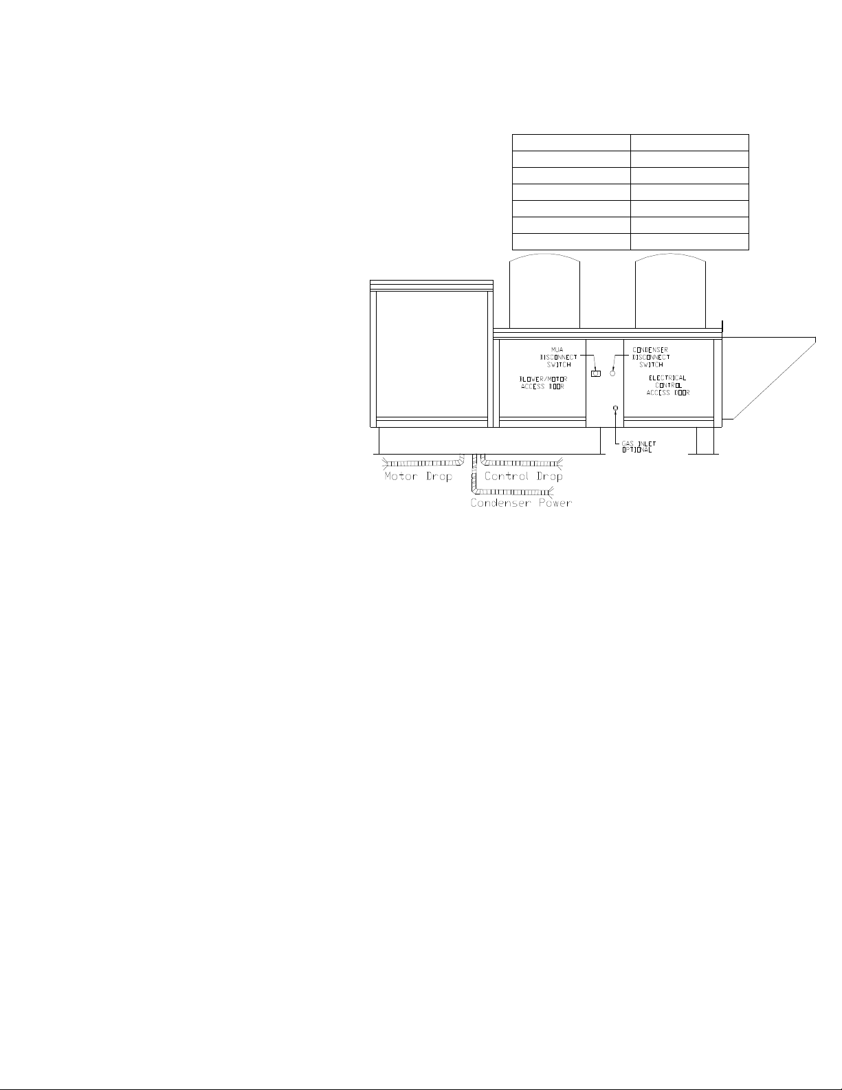
2. This unit contains 2 or 3 disconnect switches and
multiple wiring connections. 1 disconnect is for the mua
blower. The second disconnect is used for units with 2
condensers. A third disconnect is added for units with 3
condensers. An electrical drop containing the motor
power wiring and a separate
drop containing condenser
power is shipped with every
fan. The electrical drops
should be brought through
one of the conduit openings
located in the base of the unit,
run through the curb and
connected to a junction box
inside the building.
3. A dedicated branch circuit
should supply the motor circuit
with short circuit protection
according to the National
Electric Code. This dedicated
branch should be run to the
junction box mentioned above
and connected as shown in a
following illustration labeled “Fan to Building Wiring Connection”.
4. Make certain that the power source is compatible with the requirements of your equipment. The
heater nameplate identifies the proper phase and voltage of the motor. 3 phase condensers
have circuit boards that protect the compressor from running backwards. The board (located
under the condenser wiring panel) will produce a fault light if the 3 phase input needs to be
reversed to that condenser.
5. Units shipped with an optional remote panel have three electrical circuit drops. It is important to
run the motor wires in a separate conduit from the remote control wiring. The DC wires from the
unit temperature controller, located in the control drop, should either be shielded cable or be run
in a separate conduit.
6. Before connecting unit to the building power source, verify power line wiring is de-energized.
7. Secure the power cables to prevent contact with sharp objects.
8. Do not kink power cable and never allow the cable to come in contact with oil, grease, hot
surfaces or chemicals.
9. Before powering up the heater, check fan wheel for free rotation and make sure that the interior of
the heater is free of loose debris or shipping materials.
10. If any of the original wire supplied with the heater must be replaced, it must be replaced with type
THHN wire or equivalent.
Copper Wire Ampacity
Wire Size AWG Maximum Amps
14 15
12 20
10 30
8 50
6 65
4 85
8
Page 9

MUA/Condenser Fan to Building Wiring Connection
Single Phase Condenser: Condenser 1 is the Blue/Blue lines; Condenser 2 is the Red/Red lines;
Condenser 3 is the Grey/Grey lines.
Three Phase Condenser: Condenser 1 is the Blue/Blue/Blue lines; Condenser 2 is the Red/Red/Red
lines; Condenser 3 is the Grey/Grey/Grey lines.
9
Page 10

10
OPERATION
Prior to starting up or operating this unit, check all fasteners for tightness. In particular, check the set
screw in the wheel hub, bearings and the fan sheaves (pulleys). With power and/or gas OFF or prior to
connecting ventilator to power, turn the fan wheel by hand to be sure it is not striking the inlet or any
obstacles. Re-center if necessary.
WARNING: GLOVES AND SAFTEY GLASSES MUST BE WORN WHEN SERVICING
REFRIGERATION EQUIPMENT.
Start Up
Special Tools Required
• AC Voltage Meter
• Tachometer
• Standard Hand Tools
• Refrigeration Gauge Set
Start Up Procedure
• Amperage Meter
• Manometer
• Differential Pressure Gauge
• Thermometer
1. Check all electrical connections for tightness and continuity.
2. Check pulley alignment and belt tension as described below.
3. Inspect the condition of the intake damper and damper linkage, if
provided.
4. Inspect the air-stream for obstructions and install intake filters if
missing.
5. Compare the supplied motor voltage with the fan’s nameplate
motor voltage. If this does not match, correct the problem.
6. Start the fan up, by turning the external MUA disconnect to the ON
position, and shut it OFF immediately to check rotation of the
wheel with the directional arrow on the blower scroll. Reversed
rotation will result in poor air performance, motor overloading and
possible burnout. For units equipped with a single-phase motor,
check the motor wiring diagram to change rotation. For 3-phase
motors, any two power leads can be interchanged to reverse motor
direction.
7. When the fan is started up, observe the operation and check for
any unusual noises.
8. Once the fan is operating properly, turn the condenser disconnect
to the ON position. If the outside air temperature is below 55°F,
the condensers should not operate for an extended period of time.
9. Connect a refrigerant gauge set as shown below to the right.
10. Turn the cooling thermostat down to energize the first condenser.
11. Let the condenser operate for about 15 minutes and check refrigerant operating temperature and
pressure. For R410-A refrigerant, the proper suction temperature is approximately 45°F and the
proper liquid temperature is approximately 100°F. Set the refrigerant level to the proper
subcooling as indicated on the condenser label. Also, adjust the TXV to 10 degrees of superheat.
12. Disconnect the gauge set and repeat these steps on the other condensers if needed. The cooling
thermostat will need to be turned down further to energize the second or third condenser.
Page 11

11
13. If the unit is a cooling only unit, adjust the air proving switch such that prevailing winds cannot
start the condensers without the blower operating. With the unit operating, turn the adjustment
screw clockwise until condensers stop operating. Then turn the adjustment screw
counterclockwise until condensers operate. Turn the screw one half turn more counterclockwise.
14. Refer to the MUA manual to complete the startup of the MUA unit.
Checking the Refrigerant Charge
Subcooling can still be used to identify an over or under-charged system. Typical systems will run
between 10F and 20F of subcooling. If lower than 10F, the system is likely undercharged. If over 20F, the
system is probably overcharged. These "rules of thumb" are approximate. For the condensers used on
this system, the appropriate subcooling is shown below: (First number in unit size is tonnage x 12)
Subcooling is desirable because it increases the efficiency of an air conditioning system. However, too
much subcooling will back liquid up in the condenser causing increased head pressures. This will cause
the system to operate inefficiently and in extreme cases may cause the compressor to trip on its high
pressure control or its internal protector.
In the example below, a standard gauge set is connected (blue to suction and red to liquid) to a system
operating on R410A refrigerant.
The liquid line saturation temperature is reading approximately 98°F from the gauge. The surface
temperature of the liquid line is reading 83.5°F. The surface temperature reflects the actual temperature
of the refrigerant. To calculate subcooling, subtract the surface temperature from the gauge temperature:
Page 12

12
98°F – 83.5°F = 14.5°F of subcooling
This should be compared to the condenser nameplate
subcooling, which in this case is 14°F as shown to the
right.
As a reminder, to increase subcooling, add refrigerant charge and to decrease subcooling, remove
refrigerant charge.
R410A can be added to a system the same as previous R22 systems, such that it can be added as a
liquid into the suction side if done slowly to allow the refrigerant to evaporate before entering the
compressor.
Superheat and Adjusting TXVs
Ideally, the best way to check the operation of the TXV is to measure the superheat at the evaporator
outlet. In many cases this is not convenient for the technician, since there may be no gauge ports
available. A superheat check at the condensing unit can be used instead. Since suction line lengths can
vary, so too can the superheat measured at the condensing unit. With short line lengths (less than 30 ft.),
the superheat should be between 10F and 15F. With longer suction line lengths (between 30 and 50 ft.)
superheats of 15F to 20F are normal.
In the example below, a standard gauge set is connected (blue to suction and red to liquid) to a system
operating on R410A refrigerant.
The suction line saturation temperature is reading approximately 44°F from the gauge. The surface
temperature of the suction line is reading 54.1°F. The surface temperature reflects the actual
temperature of the refrigerant. To calculate superheat, subtract the gauge temperature from the surface
temperature:
54.1°F – 44°F = 10.1°F of superheat
This should be compared to the unit recommendation, which in this case is 10°F.
Page 13

13
If the superheat is too low, and an adjustable-type valve is supplied, the superheat can be increased by
turning the adjustment stem in a clockwise direction. It's a good practice to wait for 15 to 20 minutes after
adjusting the valve, to allow for the system to balance out before determining the effect of the adjustment.
If the superheat is too high, it can be lowered by turning the stem in a counter-clockwise direction.
To adjust the superheat, first remove the bottom cap from the TXV. Next, turn the adjustment screw
clockwise to increase superheat or counterclockwise to decrease superheat. Adjust about ½ turn at a
time and allow system to stabilize. Once proper superheat is set, replace the TXV cap.
Checking Heating Mode for Units with Heat Pumps
Refrigerant charge in heat pumps should be checked while the unit is in cooling mode with the same
Subcooling and Superheat method described above. However, it is also important to check heating mode
to make sure the unit is operating properly.
Attach the refrigerant gauges to the heat pump with the
red high pressure line connected to the suction line and
the blue low pressure line connected to the middle access
port as shown below.
Turn the heating thermostat up until the first heat pump
comes on. Allow the heat pump to run for 15 minutes and
check the high side pressure. The pressure should not
exceed the maximum operating pressure listed on the unit
name plate. If the pressure is high, refrigerant will need to
be removed. Removing refrigerant will also affect cooling
mode subcool and superheat, so they will need to be
checked again also.
Page 14

14
Sequence of Operation-Cooling with Direct, Indirect, or Electric Heat
This unit is most easily understood when broken down into smaller individual systems. There are two
main systems, a make-up air (MUA) fan and a cooling system. The make-up air fan consists of a blower
and motor. The cooling system consists of a condenser(s), DX coil, filter/dryer, and thermal expansion
valve.
Basic cooling units include 2 thermostats for proper operation. The first thermostat is an intake air
thermostat that prevents heating and cooling from occurring simultaneously. This is typically labeled
“Burner ON/Off Intake Air Thermostat.” This thermostat will allow the burner to operate when the outside
air temperature falls below the set point and prevents the burner from operating when the outside air
temperature rises above the set point. It also allows the cooling circuit to receive power when the outside
air temperature rises above the set point. This thermostat is typically set at 45° F and is adjustable.
The second thermostat is a cooling thermostat. The cooling thermostat allows the cooling circuit to
energize when the outside air rises above the set point. This is a 2 stage, differential thermostat; one set
point that energizes where the thermostat is set and a second stage that energizes at a factory setting of
10° F higher. The main set point controls the first stage of cooling and the differential controls the second
stage of cooling. This thermostat is factory set at 85° F; the factory setting and subsequent differential
setting are both adjustable.
With the blower already running and the airflow switch proven;
The air temperature rises above the setting of intake air thermostat and the cooling
thermostat
OR
The optional remote panel is set to “Manual” and “Cool” mode, and the temperature rises
above both thermostats as mentioned above.
• The first stage condenser energizes and cooling starts.
• The air temperature continues to rise above the cooling thermostat differential and the second stage
of cooling (if equipped) is energized.
• Once the air temperature falls below the differential, the second stage of cooling is de-energized.
• Once the air temperature falls below the cooling thermostat set point, both stages of cooling are de-
energized.
Cooling Thermostat on Left, Burner/Heat Thermostat on Right
***AN OPTIONAL PROGRAMMABLE THERMOSTAT
IS AVAILIBLE. WHEN THIS IS PROVIDED, AN AS
BUILT SCHEMATIC AND A SEPARATE MANUAL IS
PROVIDED FOR THE THERMOSTAT***
Page 15

15
Sequence of Operation-Reheat
The unit can be equipped with an optional reheat coil downstream from the DX coil. When this option is
installed, warm, liquid refrigerant will flow through a reheat coil before it enters the DX coil. This warms
the cooled air discharged from the DX coil and helps to lower the relative humidity of the airstream.
Reheat is always activated in this system, and only uses refrigerant from stage 1.
Sequence of Operation-Liquid Bypass
This system can be installed with a Liquid Bypass option. This option helps prevent coil freezing by
injecting warm liquid refrigerant directly into the DX coil, bypassing the TXV. The system is controlled by
a Bypass Thermostat whose sensing bulb is strapped to the vertical portion of the stage 1 suction line.
When the Bypass Thermostat reads a temperature below 35º F, it sends a signal to a 24V solenoid valve.
The valve opens and allow warm liquid refrigerant to bypass the TXV and go directly into the DX coil.
Once the thermostat reads a temperature above 35º F in the suction line, it shuts off the solenoid valve
and the system continues to operate normally.
Sequence of Operation-Cooling Only or Heat Pump
Onboard HMI
• MENU – Used to revert back one screen each
time it is pressed. If any value has been altered
and the menu button is pressed, that value will
save.
• UP – Used to navigate up through the current
list of items.
• DOWN – Used to navigate down through the
current list of items
• ENTER – Used to advance once screen each
time it is pressed. If any value has been altered
and the enter button is pressed, that value will
save.
(If any value has been changed, the board will automatically reboot when the user exits to the
home screen)
Info
• Temperature – Contains values for Discharge, Return, Outside Intake, Space, Mixed Air,
Outdoor-Discharge ∆T, and Return-Discharge ∆ T. Will show disconnected if there is no sensor
present.
• Date/Time – Displays time and date based on real time clock (RTC).
• Outputs – Output voltage to RTU out 0-10V #1.
• Timers – Displays uptime of the board.
• Mixed Air Info – Displays live outdoor air % and return air %.
Configuration
• Modbus Address – This address which will be used to communicate with the board.
• # Of Stages – Configurable to 1, 2, or 3 stages.
• Control Mode – Auto (heat/cool), heat, cool, off.
• Staged Based On – Outside, space.
• Activate Based On – Outside, space, both, either.
Page 16

16
Faults
• Space Cool SP – Stage 1 space cooling set point.
• Space Cool SP #2 – Stage 2 space cooling set point.
• Space Cool SP #3 – Stage 3 space cooling set point.
• Space Heat SP – Stage 1 space heating set point.
• Space Heat SP #2 – Stage 2 space heating set point.
• Space Heat SP #3 – Stage 3 space heating set point.
• Outdoor Cool SP – Stage 1 outdoor cooling set point.
• Outdoor Cool SP #2 – Stage 2 outdoor cooling set point.
• Outdoor Cool SP #3 – Stage 3 outdoor cooling set point.
• Outdoor Heat SP – Stage 1 outdoor heating set point.
• Outdoor Heat SP #2 – Stage 2 outdoor heating set point.
• Outdoor Heat SP #3 – Stage 3 outdoor heating set point.
(All tempering set points may not be available depending on the selected # of
stages and staging/activation selections)
• Min. Outdoor Air Temp – This value is in place to ensure that a unit is not trying to cool
when the ambient outside temperature is too low. This will help prevent coils from
freezing. It is factory set at 60° F and adjustable between 55-65° F.
• O/B Output Mode – This option allows you to choose whether the output energizes during
cooling or heating. This output is driven by what company heat pump is being utilized.
Carrier’s standard is to energize with cooling.
• Mode Change Time – This time dictates how long the unit must wait before switching
from heating to cooling or vice versa. Factory set at 5 minutes. Adjustable between 1-10
minutes.
• Heat Hysteresis – Factory set a 1° F, adjustable between 1-5° F.
• Cool Hysteresis – Factory set a 1° F, adjustable between 1-5° F.
• Min. Heat On Time – Time any heating stage must stay on after being activated. Factory
set at 2 minutes. Adjustable between 1-5 minutes.
• Min. Cool On Time – Time any cooling stage must stay on after being activated. Factory
set at 2 minutes. Adjustable between 1-5 minutes.
• Min. Heat Off Time – Time any heating stage must stay off after being de-activated.
Factory set at 2 minutes. Adjustable between 1-5 minutes.
• Min. Cool Off Time – Time any cooling stage must stay off after being de-activated.
Factory set at 2 minutes. Adjustable between 1-5 minutes.
• Mixing Box Type – Selectable between none, external, and adjustable. Choosing
external or adjustable both enables the use of return and mixed air sensors. When
adjustable is chosen it also enables the 0-10V damper position output on the board.
• Damper Position – This is a user selectable 0-100 percent, and once set, the board will
try to maintain that percentage of outdoor air by altering its output voltage to the damper.
• MB Deadband – This relates to the absolute value of the delta T between outdoor air and
return air. If the delta T falls within the deadband range, the board will not alter its output
voltage to the damper. The voltage will be a constant 0-10V directly related to the 0-100
damper position. Factory set at 5° F and adjustable between 1-10° F.
• Return As Space – This option is enabled when a mixing box is selected. If an adequate
space sensor can’t be mounted within the space, the board has the ability to treat the
return air sensor as the space sensor.
• Startup Time – Delay upon powering up until the board allows any pins to be active.
Factory set at 5 seconds.
• Reboot – Reboots the board.
• Factory Reset – Resets the board to the last commissioned settings.
• View Faults – This menu will store faults even once the board has lost power. Possible
faults include airflow, alarm 1 (float switch), heating discharge, and cooling discharge.
Heating and cooling discharge faults occur when there has been no ∆T for 30 minutes.
Page 17

17
Diagnostics
• Clear Faults – Once the faults have been resolved, choosing this option will wipe them
from the board’s memory. If the fault has not been resolved, it could re-appear on the
view faults screen.
• RTU Y1 – Option to enable or disable Y1 (stage 1) output.
• RTU Y2 – Option to enable or disable Y2 (stage 2) output.
• RTU Y3 – Option to enable or disable Y3 (stage 3) output.
• RTU O/B – Option to enable or disable O/B output.
• RTU 10V Out 1 – 0-10V adjustable output
• Exit – In order to back out of diagnostics mode, this menu item must be selected.
Page 18

18
Board Menu
Page 19

19
Components
The following image outlines the typical modular packaged unit components. Systems are available with
heating modules, mixing boxes and 1, 2 or 3 condensers.
Thermal Expansion Valves Filter/Dryer
Page 20

20
Troubleshooting
Problem
Potential Cause
Corrective Action
The following tables list causes and corrective actions for possible problems with the units. Review these
lists prior to consulting manufacturer.
Troubleshooting Chart
Fan Inoperative Blown fuse or open circuit breaker Replace fuse or reset circuit breaker
Disconnect switch in “Off” position Turn to “On” position
Motor wired incorrectly Check motor wiring to wiring diagram
Broken fan belt Replace belt
Motor starter overloaded Reset starter and check amps
Remote panel set to “Off” Position Set Remote Panel to “Manual” or “Auto”
Motor Overload Fan rotating in the wrong direction Be sure fan is rotating in the direction
Fan speed is too high Reduce fan RPM
Motor wired incorrectly Check motor wiring to wiring diagram
Overload in starter set too low Set overload to motor FLA value
Motor HP too low Determine if HP is sufficient for job
Duct static pressure lower than design Reduce fan RPM
Insufficient Airflow Fan rotating in the wrong direction Be sure fan is rotating in the direction
Poor outlet conditions There should be a straight clear duct at
Intake damper not fully open Inspect damper linkage and replace
Duct static pressure higher than design Improve ductwork to eliminate or reduce
Blower speed too low Increase fan RPM. Do not overload
Supply grills or registers closed Open and adjust
Dirty or clogged filters Clean and/or replace
Belt slippage Adjust belt tension
Excessive Airflow Blower speed too high Reduce fan RPM
Filters not installed Install filters
Duct static pressure lower than design Reduce fan RPM
Excessive Vibration and Noise Misaligned pulleys Align pulleys
Damaged or unbalanced wheel Replace wheel
Fan is operating in the unstable region of
the fan curve
Bearings need lubrication or replacement Lubricate or replace
Fan speed is too high Reduce fan RPM
Belts too loose, worn or oily Inspect and replace if needed
No Cooling Condenser Disconnect is Off Turn Disconnect to ON Position
Outside Air Temp is cooler then
thermostat setting
Frozen Coil Ensure airflow through unit is correct
Refrigerant Leak Ensure refrigerant has not leaked out of
Insufficient Cooling Excessive Airflow Reduce the airflow volume
Incorrect Refrigerant Charge Refrigerant charge must be checked by
and check amps
located on fan motor
Position
shown on rotation label
located on fan motor
shown on rotation label
the outlet
damper motor if needed
duct losses
motor
Refer to performance curve for fan
Turn thermostat to desired cooling
activation set point. Do not turn below
55° F.
and refrigeration charge is correct. Low
airflow will cause the coil to freeze.
unit.
a refrigeration contractor
Page 21

21
MAINTENANCE
To guarantee trouble free operation of this unit, the manufacturer suggests following these guidelines.
Most problems associated with fan failures are directly related to poor service and maintenance.
Please record any maintenance or service performed on this fan in the documentation section located at
the end of this manual.
WARNING: DO NOT ATTEMPT MAINTENANCE ON THE UNIT UNTIL THE
ELECTRICAL SUPPLY HAS BEEN COMPLETELY DISCONNECTED AND THE
MAIN GAS SUPPLY VALVE (IF REQUIRED) HAS BEEN TURNED OFF.
General Maintenance
1. Fan inlet and approaches to ventilator should be kept clean and free from any obstruction.
2. Motors are normally permanently lubricated. Check bearings periodically. If they have grease
fittings, lubricate each season. Use caution when lubricating bearings - wipe the fittings clean and
the unit should be rotated by hand while lubricating. Caution: Use care when touching the
exterior of an operating motor. Motors normally run hot and may be hot enough to be
painful or cause injury.
3. All fasteners should be checked for tightness each time maintenance checks are performed prior
to restarting unit.
4. Blowers require very little attention when moving clean air. Occasionally, oil and dust may
accumulate causing imbalance. If the fan is installed in a corrosive or dirty atmosphere,
periodically inspect and clean the wheel, inlet and other moving parts to ensure smooth and safe
operation.
5. Do not block or cover airflow to condensing units. Do not allow grass clippings, leaves or other
debris to accumulate on the sides or top of the unit.
6. Do not operate the air conditioning system when the outdoor air is less then 55° F.
2 weeks after startup
1. Belt tension should be checked after the first 2 weeks of fan operation. Belts tend to stretch and
settle into pulleys after an initial start-up sequence. Do not tension belts by changing the
setting of the motor pulley, this will change the fan speed and may damage the motor. To retension belts, turn the power to the fan motor OFF. Loosen the fasteners that hold the blower
scroll plate to the blower. Rotate the motor to the left or right to adjust the belt tension. Belt
tension should be adjusted to allow 1/64” of deflection per inch of belt span. Exercise extreme
care when adjusting V-belts, as not to misalign pulleys. Any misalignment will cause a sharp
reduction in belt life and produce squeaky noises. Over-tightening will cause excessive belt and
bearing wear, as well as noise. Too little tension will cause slippage at startup and uneven wear.
Whenever belts are removed or installed, never force belts over pulleys without loosening
motor first to relieve belt tension. When replacing belts, use the same type as supplied by the
manufacturer. On units shipped with double groove pulleys, matched belts should always be
used.
2. All fasteners should be checked for tightness each time maintenance checks are performed prior
to restarting unit.
Every 3 months
1. Belt tension should be checked quarterly. See instructions in the previous maintenance section.
Over-tightening will cause excessive bearing wear and noise. Too little tension will cause
slippage at startup and uneven wear.
Page 22

22
2. Filters need to be cleaned and/or replaced quarterly, and more often in severe conditions.
Washable filters can be washed in warm soapy water. When re-installing filters, be sure to install
with the airflow in the correct direction as indicated on the filter.
3. Check for and remove debris that has settled around the base of the condenser. This will ensure
proper water drainage from the condenser.
Yearly
1. Inspect bearings for wear and deterioration. Replace if necessary.
2. Inspect belt wear and replace torn or worn belts.
3. Inspect bolts and set screws for tightness. Tighten as necessary.
4. Inspect motor for cleanliness. Clean exterior surfaces only. Remove dust and grease from the
motor housing to ensure proper motor cooling. Remove dirt and grease from the wheel and
housing to prevent imbalance and damage.
Page 23

23
Start-Up and Maintenance Documentation
START-UP AND MEASUREMENTS SHOULD BE PERFORMED AFTER THE SYSTEM HAS BEEN
AIR BALANCED AND WITH THE COOLING ON (Warranty will be void without completion of this
form).
Job Information
Job Name Service Company
Address Address
City City
State State
Zip Zip
Phone Number Phone Number
Fax Number Fax Number
Contact Contact
Purchase Date Start-Up Date
Unit Information
Refer to the start-up procedure in this manual to complete this section.
Name Plate and Unit Information
Model Number
MUA Serial Number
Motor Volts
Motor Hertz
Motor Phase
Motor FLA
Motor HP
Blower Pulley
Motor Pulley
Belt Number
Gas Type
Min. Btu/Hr
Max. Btu/Hr
COND 1 Serial Number
COND 2 Serial Number
COND 3 Serial Number
**
If measured amps exceed the FLA rating on the nameplate, fan RPM must be reduced to decrease the
measured amps below the nameplate FLA rating.
Field Measured Information
Motor Voltage
Motor Amperage**
MUA Blower RPM
Ambient Wet Bulb Temp °F
Ambient Dry Bulb Temp °F
COND 1 Suction Pressure PSI
COND 1 Suction Temperature °F
COND 1 Liquid Pressure PSI
COND 1 Liquid Temperature °F
COND 1 Subcooling °F
COND 1 Superheat °F
COND 2 Suction Pressure PSI
COND 2 Suction Temperature °F
COND 2 Liquid Pressure PSI
COND 2 Liquid Temperature °F
COND 2 Subcooling °F
COND 2 Superheat °F
COND 3 Suction Pressure PSI
COND 3 Suction Temperature °F
COND 3 Liquid Pressure PSI
COND 3 Liquid Temperature °F
COND 3 Subcooling °F
COND 3 Superheat °F
Cooling Thermostat Set-Point °F
Airflow Direction Correct
Incorrect
Page 24

24
Maintenance Record
Date Service Performed
Factory Service Department
Phone: 1-866-784-6900
Fax: 1-919-554-9374
 Loading...