

Page 1
Modular DX System
Installation Instructions
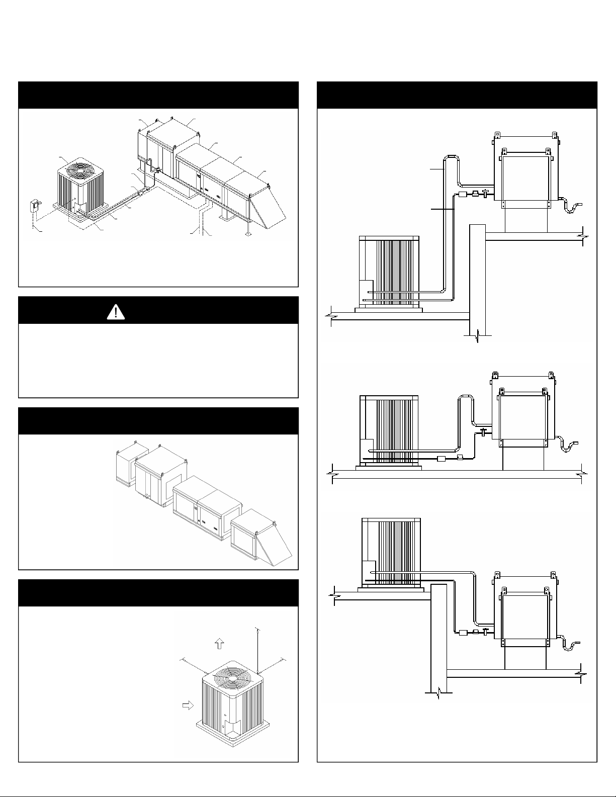
TYPICAL PIPING AND WIRING
Downturn
Plenum
Condensing
Unit
Weatherproof
Fused
Disconnect
Per NEC
Field Wired
Power Supply
Notes:
1. Read the equipments “Installation and Operation Guide” before installing this equipment.
2. All Piping must follow standard refrigerant piping techniques.
3. All wiring must comply with all local and national codes.
4. Call the factory service department with any installation questions.
Sight Glass
Filter Drier
Liquid Line
Field Wired
Control Wires
Suction Line
Field Wiring
Power Supply
Per NEC
DX Coil Module
Field Wiring
Remote Panel
(Optional)
Blower Module
WARNING
• Installing, start-up, and servicing air-conditioning
equipment can be dangerous due to system pressures,
electrical components, and equipment locations.
• Only trained, qualified installers and service technicians
should install, start-up, and service this equipment.
• Untrained personal can perform basic maintenance
functions such as cleaning coils. All other operations
should be performed by trained service personnel.
• When working on the equipment, observe precautions
in the literature and on decals, labels, and tags attached
to the equipment.
• Follow all safety codes. Wear safety glasses and work
gloves. Keep quenching cloth and fire extinguisher
nearby when braising.
• Use safe lifting practices when lifting and setting
equipment.
Heater Module
Filter
Section
REFRIGERANT PIPING PRACTICES
Typical Piping When Condenser Is Below The AMU
Suction Line
with a 16”
Refrigerant
Trap
Liquid Line
Condenser
Roof
Typical Piping On Same Level
Condenser
AMU
Curb
Roof
Condensate
Trap
INSPECT UNIT
• Inspect unit for damage.
• Look for damage done to the
casing, coils, or ship loose
components.
• Contact factory service depart-
ment if damage is found on the
unit.
• Verify that the power and gas
supply to the unit matches the
unit nameplate ratings.
• Call the factory service depart-
ment with any installation
questions.
INSTALL CONDENSING UNIT
• Read the customer supplied Condenser Installation manual
before attempting to install, pipe, or wire the unit. The
manufacturer of the Condenser may have special instructions for installing that is not mentioned in this document.
• Contact the Condenser manufacturer with any installation
questions.
• Mount the Condenser in a location where adequate air flow
and service space is available.
• The Condensing units comes with a factory refrigerant
charge. Do not open the ball valves until the plumbing has
been completed and tested for leaks.
• Refer to the Condenser Installation manual for suction and
liquid line sizes and maximum lengths.
• Refer to the Condenser Installation manual for general wiring
practices. All wiring must comply with all local and national
codes.
• Refer to the Cooling Circuit Wiring in this document for
instructions on connecting to the Make-Up Air unit electrical
panel.
Air Flow
Minimum
Clearance
24”
Air Flow
Minimum
Clearance
60”
Minimum
Clearance
24”
Suction Line
with a 16”
Refrigerant
Trap
Liquid Line
Roof
Typical Piping When AMU Is Below Condenser
Condenser
Suction Line
Roof
Notes:
1. Maximum refrigerant line length 100 feet.
2. Do not bury refrigerant lines underground.
3. Accumulators are required on refrigerant line lengths of 75 to 100 feet.
4. Maximum refrigerant liquid lift 60 feet.
5. Dual circuit systems require two suction and liquid lines.
Liquid
Line
AMU
Curb
AMU
Roof
Curb
Condensate
Trap
Condensate
Trap
Page 2
WARNING
Disconnect power before installing or servicing fan. High voltage electrical input is needed for this
Electrical wiring must be done in accordance with local ordinances and the National Electric Code, ANSI/
NFPA70. Be sure the voltage and phase of the power supply and the wire amperage capacity conform to those
listed on the units nameplate. For additional safety information, refer to AMCA publication 410-96,
equipment. This work should be performed by a qualified electrician.
“Recommended Safety Practices for Users and Installers of Industrial and Commercial Fans.”
ELECTRICAL CONNECTIONS
AMU POWER SUPPLY
Check that the power supply matches the units
nameplate rating.
Wire the disconnect using NEC and local
codes. Size the wire according to the units
minimum circuit amps.
SW-01 MAIN DISCONNECT SWITCH
ST-01 SUPPLY MOTOR CONTACTOR
CB-01 CIRCUIT BREAKER
TR-01 POWER TRANSFORMER
CONDENSER POWER SUPPLY
Check that the power supply matches the units
nameplate rating.
Wire the disconnect using NEC and local
codes. Size the wire according to the units
minimum circuit amps.
CAUTION
Condensing units contain a factory holding charge of refrigerant .
Opening the liquid or suction line shut-off valves before the piping
has been braised, evacuated, and leak tested may result in
Section 608 of the “Clean Air Act”, prohibits individuals from
knowingly venting ozone-depleting compounds (refrigerant) into the
atmosphere while installing, maintaining, servicing, repairing, or
EPA performs random inspections, responds to tips, and pursues
potential violators. Under the Act, EPA is authorized to fine up to
releasing the holding charge.
EPA Section 608 Clean Air Act
disposing of air-conditioners or refrigeration equipment.
$32,000 per day for any violation of these regulations.
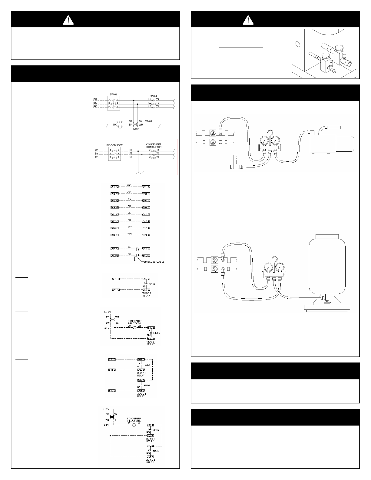
EVACUATION & REFRIGERANT CHARGING
EVACUATION
Suction Line
Valve
Liquid Line
Valve
Micron Gauge
Refrigerant Gauge
Vacuum Pump
AMU units that ship with a optional remote
panel must be field wired before starting the
unit.
The AMU terminal block will correspond with
the remote panel terminal block.
Use shielded cable on the wires for T1 and T3
for the remote set-point dial, or run the wired in
a separate conduit from the power wiring.
CONDENSER SINGLE COMPRESSOR (A)
Option A
Wire single compressor condensers with R-GY-W-C terminals to the AMU as shown.
Refer to the condensers installation manual for
additional wiring directions.
CONDENSER SINGLE COMPRESSOR (B)
Option B
Wire single compressor condensers without RG-Y-W-C terminals to the AMU as shown.
Refer to the condensers installation manual for
additional wiring directions.
CONDENSER DUAL COMPRESSOR (A)
Option A
Wire dual compressor condensers with R-G-YW-C terminals to the AMU as shown.
Refer to the condensers installation manual for
additional wiring directions.
REMOTE PANEL
• Leave suction and liquid line valves closed
• Open both refrigerant gauge valves and turn the vacuum pump ON
• Evacuate the system until the micron gauge reads less than 500 microns
• Repair leaks or check the hose connections if the micron gauge does not reach 500 microns
• Close the refrigerant gauge valves and turn the vacuum pump OFF
CHARGING
Check the condensing unit Installation Manual and documentation on charging instructions.
Some condensing unit come with the full operating refrigerant charge.
Suction Line
Valve
Liquid Line
Valve
Check the condensing units Installation Manual and documentation on charging information, some condensing
•
units come with the full operating refrigerant charge
• After evacuating the system, charge the system with 80% of the operating charge shown on the condensing units
name plate
• After starting the unit add the remaining refrigerant charge and fine tune the charge so the units super-heat is
around 8 to 12 F
Refrigerant Gauge
Refrigerant Tank
Scale
• Remove the gauge lines and replace the suction and liquid line valve caps.
START-UP
CONDENSER DUAL COMPRESSOR (B)
Option B
Wire dual compressor condensers without RG-Y-W-C terminals to the AMU as shown.
Refer to the condensers installation manual for
additional wiring directions.
Read the condensing unit and AMU installation, start-up, and operation guides
Fill out the start-up check lists and send them to the Factory Service Department
TECHNICAL SERVICE
Need additional help or have other questions?
Contact the factory service department.
715-595-4225 office
919-227-5959 fax
 Loading...