

FloAire INDIRECT FIRED BENT TUBE MODULE User Manual

FOR YOUR SAFETY
Modular
In-Direct Fired
Heater
s and Inserts
Installation, Operation, and Maintenance Manual
Modular
In-
Direct
Fired
Heater
In-
Direct Fired Module
Save these inst
ructions
R
ECEIVING AND INSPECTION
WARNING!!
FOR YOUR SAFETY
In-Direct Fired Furnace
If you smell gas:
1. Open windows.
2. Don’t touch electrical switches.
3. Extinguish any open flames.
4. Immediately call your gas supplier.
The use and storage of gasoline or other flammable vapors and liquids in open containers in the
vicinity of this appliance is hazardous.
Upon receiving unit, check for any interior and exterior damage, and if found, report it
immediately to the carrier. Also check that all accessory items are accounted for and are
damage free. Turn the blower wheel by hand to verify free rotation and check the damper (if
supplied) for free operation.
Improper installation, adjustment, alteration, service or maintenance can cause property
damage, injury or death. Read the installation, operating and maintenance instructions
thoroughly before installing or servicing this equipment. ALWAYS disconnect power and gas
prior to working on heater.
. This document is the property of the owner of this equipment and is
required for future maintenance. Leave this document with the owner when installation or
service is complete.
A0016988
January, 2014 Rev. 21

TABLE OF CONTENTS
WARRANTY ...................................................................................................................................................................................... 3
INSTALLATION ................................................................................................................................................................................. 4
Mechanical ................................................................................................................................................................................... 4
Site Preparation ...................................................................................................................................................................... 4
Assembly ................................................................................................................................................................................ 4
Curb and Ductwork ................................................................................................................................................................. 4
Recommended Supply Ductwork Sizes ................................................................................................................................... 5
Condensation Drain ................................................................................................................................................................ 5
Roof Mount Installation............................................................................................................................................................ 6
Installation with Exhaust Fan ................................................................................................................................................... 6
Indirect Fired Module Installation ............................................................................................................................................. 7
Indoor (INLINE) Installation ..................................................................................................................................................... 7
Indoor Flue Venting ................................................................................................................................................................. 8
Gas ............................................................................................................................................................................................ 11
Electrical .................................................................................................................................................................................... 12
PSC (Permanent Split Capacitor) Motor Speed Control ......................................................................................................... 13
ECM (Electronically Controlled Motor) Speed Control ........................................................................................................... 13
Electric Cabinet Heater ......................................................................................................................................................... 14
Motorized Intake Damper ...................................................................................................................................................... 14
Remote Control Panel ........................................................................................................................................................... 14
Fan to Building Wiring Connection ........................................................................................................................................ 15
OPERATION ................................................................................................................................................................................... 15
Start Up ...................................................................................................................................................................................... 15
Special Tools Required ......................................................................................................................................................... 15
Start Up Procedure ............................................................................................................................................................... 15
Forced High Fire Light-Off (Modulating Stages) .................................................................................................................... 16
High-Fire and Low-Fire Burner Adjustment............................................................................................................................ 16
Gas Pressure Adjustment Reference Information (Natural Gas) ............................................................................................ 18
Furnace Start-Up Summary................................................................................................................................................... 19
Final Start-Up Procedure ....................................................................................................................................................... 20
Pulley Adjustment ................................................................................................................................................................. 21
Pulley Alignment/Proper Belt Tension ................................................................................................................................... 21
Pulley Combination Chart ...................................................................................................................................................... 22
Sequence of Operation ............................................................................................................................................................... 23
Modulating Gas System ........................................................................................................................................................ 23
Flame Safety Control ............................................................................................................................................................ 24
Modulating Stage Sequence ................................................................................................................................................. 24
FVFAB and High Fire Start .................................................................................................................................................... 25
Re-Circulating Control Options ................................................................................................................................................... 25
Manual Positioning Control (Potentiometer) .......................................................................................................................... 25
Two Position Control ............................................................................................................................................................. 25
Static Pressure Control (Photohelic) ...................................................................................................................................... 26
A306 Outdoor Sensor ........................................................................................................................................................... 27
Building Signal Damper Control ............................................................................................................................................ 27
Operation Summary ................................................................................................................................................................... 27
Optional Remote Panel Circuit .............................................................................................................................................. 28
Components.......................................................................................................................................................................... 29
Remote Panel Option ............................................................................................................................................................ 31
Modulating Furnace Thermostat Dip Switch Settings ............................................................................................................ 32
FVFAB Settings .................................................................................................................................................................... 32
High Altitude Orifice Sizing .................................................................................................................................................... 33
Troubleshooting.......................................................................................................................................................................... 34
Airflow Troubleshooting Chart ............................................................................................................................................... 34
Furnace Troubleshooting Chart ............................................................................................................................................. 35
Remote Panel Troubleshooting Chart ................................................................................................................................... 36
Troubleshooting Flow-charts ................................................................................................................................................. 37
MAINTENANCE .............................................................................................................................................................................. 39
General Maintenance ................................................................................................................................................................. 39
2 weeks after startup .................................................................................................................................................................. 40
Every 3 months .......................................................................................................................................................................... 40
Yearly ......................................................................................................................................................................................... 41
Start-Up and Maintenance Documentation ................................................................................................................................. 42
Job Information ..................................................................................................................................................................... 42
Heater Information ................................................................................................................................................................ 42
Maintenance Record ............................................................................................................................................................. 42
Factory Service Department .................................................................................................................................................. 42
2

WARRANTY
This equipment is warranted to be free from defects in materials and workmanship, under normal use and
service, for a period of 12 months from date of shipment. All Heat Exchangers have a standard 10 year
Pro-rated manufacturer-backed warranty. This warranty shall not apply if:
1. The equipment is not installed by a qualified installer per the MANUFACTURER’S installation
instructions shipped with the product,
2. The equipment is not installed in accordance with federal, state and local codes and regulations,
3. The equipment is misused or neglected,
4. The equipment is not operated within its published capacity,
5. The invoice is not paid within the terms of the sales agreement.
The MANUFACTURER shall not be liable for incidental and consequential losses and damages
potentially attributable to malfunctioning equipment. Should any part of the equipment prove to be
defective in material or workmanship within the 12-month warranty period, upon examination by the
MANUFACTURER, such part will be repaired or replaced by MANUFACTURER at no charge. The
BUYER shall pay all labor costs incurred in connection with such repair or replacement. Equipment shall
not be returned without MANUFACTURER’S prior authorization and all returned equipment shall be
shipped by the BUYER, freight prepaid to a destination determined by the MANUFACTURER.
3
INSTALLATION
CLEARANCES
IMPORTANT
It is imperative that this unit is installed and operated with the designed airflow, gas, and electrical supply
in accordance with this manual. If there are any questions about any items, please call the service
department at 1-866-784-6900 for warranty and technical support issues.
Mechanical
WARNING: DO NOT RAISE VENTILATOR BY THE INTAKE HOOD, BLOWER OR
MOTOR SHAFT, OR BEARINGS – USE LIFTING LUGS PROVIDED OR A SLING
Site Preparation
1. Provide clearance around installation site to safely rig and
lift equipment into its final position. Supports must
adequately support equipment. Refer to manufacturer’s
estimated weights.
2. Consider general service and installation space when
locating unit.
3. Locate unit close to the space it will serve to reduce long,
twisted duct runs.
4. Do not allow air intake to face prevailing winds. Support
unit above ground or at roof level high enough to prevent
precipitation from being drawn into its inlet. The inlet must
also be located at least 10 feet away from any exhaust
vents. The heater inlet shall be located in accordance
with the applicable building code provisions for ventilation
air.
Assembly
Intakes and curbs are shipped unassembled to heater module.
Upon unit arrival, use the following procedure to assemble the
intake to the heater.
1. Apply silicone or weather-proof gasket on the back side of
the flanges of the intake hood or v-bank intake.
2. Screw the flanges of the intake hood or v-bank to the unit with the supplied sheet metal screws.
Place caulk on the outside
of the screws to prevent
water leaks. If the unit is a
modular unit with a v-bank
or evaporative cooler
section, the v-bank or
evaporative cooler will bolt
to the heater with the bolts
provided.
The top, back, and front
surfaces of this heater may not
be installed less than 6” from
combustible materials. The
heater base may be installed
on combustible surfaces.
Allow 24” minimum service
clearance on both sides of this
heater.
To prevent premature heat
exchanger failure, do not
locate any gas fired unit in
areas where chlorinated,
halogenated, or acid vapors
are present in the atmosphere.
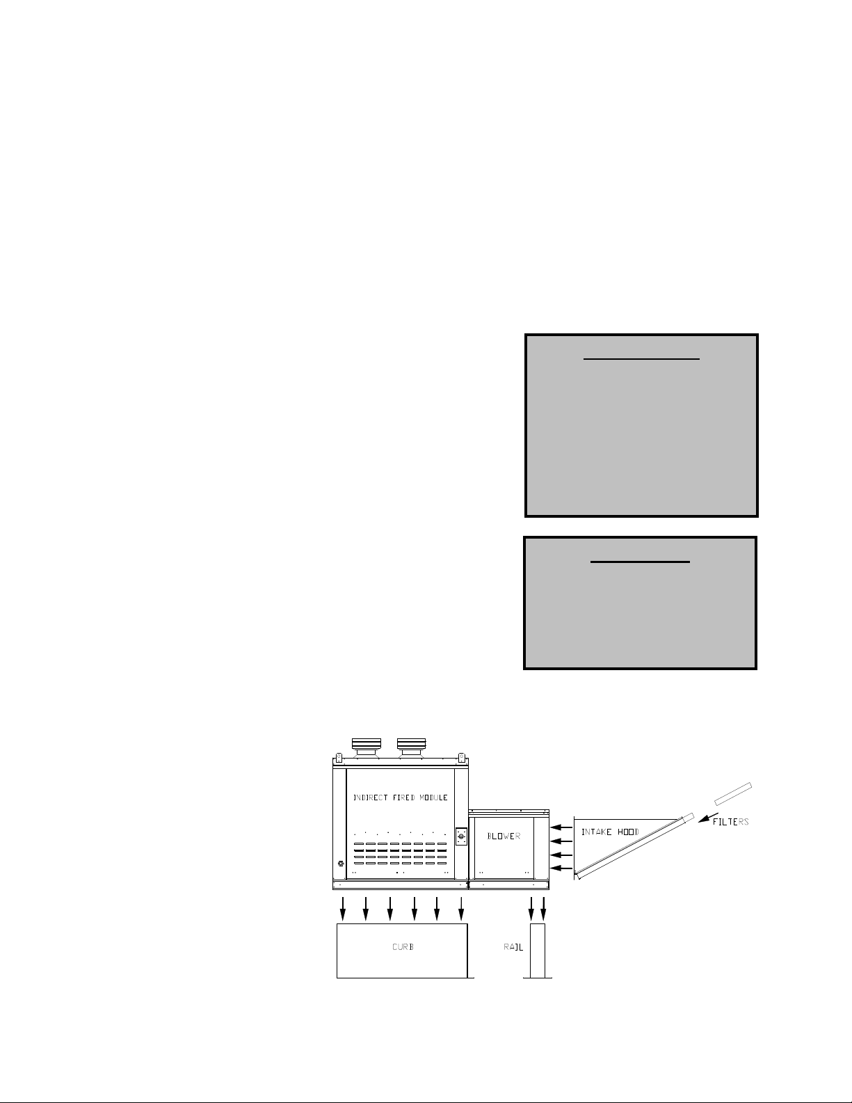
Curb and Ductwork
This fan was specified for a
specific CFM and static pressure.
The ductwork attached to this unit
will significantly affect the airflow
performance. Flexible ductwork
4
and square elbows should not be used. Also,
transitions and turns in ductwork near the fan
outlet will cause system effect and will drastically
increase the static pressure and reduce airflow.
The chart below shows the minimum fan outlet
duct sizes and straight lengths recommended for
optimal fan performance. Follow SMACNA
guides and recommendations for the
remaining duct run. Fans designed for rooftop
installation should be installed on a
prefabricated or factory built roof curb. Follow
curb manufacturer’s instructions for proper curb installation. The unit should be installed on a curb and/or
rail elevated not less than 20” above any surface. Be sure duct connection and fan outlet are properly
aligned and sealed. Secure fan to curb through vertical portion of the ventilator base assembly flange
using a minimum of eight (8) lug screws, anchor bolts, or other suitable fasteners (not furnished). Shims
may be required depending upon curb installation and roofing material. Check all fasteners for tightness.
The diagrams below show different mechanical installation configurations.
Recommended Supply Ductwork Sizes
Blower Size Duct Size Straight Duct Length
10 14 x 14 48 in.
12 16 x 16 54 in.
15 20 x 20 72 in.
18 24 x 24 86 in.
20 26 x 26 108 in.
25 32 x 32 168 in.
Condensation Drain
In some applications, condensation can form in the flue collection box, especially when furnaces are
located downstream of cooling coils. In the event that condensation occurs in the flue collection boxes,
there are barbed fittings in the bottom of the flue collection boxes to drain condensation out of the boxes.
Each burner in the unit is provided with a burner drain pan or a condensation drain assembly located
underneath this fitting for the condensation to collect. If the drain assembly is installed on the heater, it will
have ¼” quick seals located below the front access door for field piping or drainage onto the roof. Consult
your local code as to the proper drainage regulations of the condensation. The internal drain piping is
heated to prevent freezing. If drains are field piped, ensure that the field piping is piped in a fashion to
prevent the condensation from freezing. Do not plug the holes under any circumstance as it will cause the
burners to overflow.
In the event the IBT does not have condensation drains and condensation exceeds the pan capacity, IBT
condensation drain kits can be ordered for installation in the field.
The part names for the kits are:
“IBT Condensation Kit-1” Single Furnace IBT
“IBT Condensation Kit-2” Double Furnace IBT
“IBT Condensation Kit-3” Triple Furnace IBT
“IBT Condensation Kit-4” Quadruple Furnace IBT
IBT Condensation Drain Assembly ¼” NPT Condensation Drain Connections
5
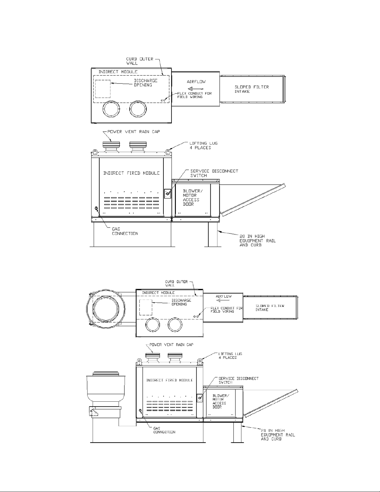
Roof Mount Installation
Installation with Exhaust Fan
6
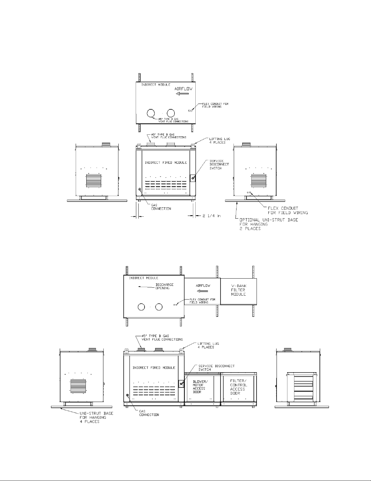
Indirect Fired Module Installation
Indoor (INLINE) Installation
7
Indoor Flue Venting
IMPORTANT
fan.
IMPORTANT
fan.
Indoor gas fired heating equipment must be vented. Do not operate unvented. Gas fired heating equipment which has been improperly vented,
or which experiences a blocked vent condition may emit flue gases into
heated spaces.
General Venting Guidelines
1. Installation of venting must conform with local building codes, or
in the absence of local codes, follow the National Fuel Gas Code.
2. On Units with multiple furnaces, each furnace must be ducted to the outside using its own
isolated duct run. Ducts used on each single furnace must Not be Connected together in
any fashion. Failure to adhere to this may result in a build-up of Carbon-Monoxide in the
space when the furnace is operating with less than all of its furnaces powered.
3. Do not use a vent pipe smaller than the size of the outlet on the heater.
4. Install with a minimum upward slope from unit of ¼ inch per foot and suspend from overhead
structure at points no greater than 3 feet apart. For best venting, put as much vertical vent as
close to the unit as possible.
5. Fasten individual lengths of vent together with at least three corrosion resistant sheet metal
screws.
6. Vent pipes should be fitted with a tee with a drip leg and clean out tap at the low point in the vent
run. This should be inspected and cleaned out periodically during the heating season.
7. Do NOT use dampers or other devices in the vent or combustion air pipes.
8. Use a vent terminal to reduce downdrafts and moisture in the vent line.
9. A vent system that terminates vertically but has a horizontal run that exceeds 75% of the vertical
rise is considered horizontal.
10. Pressures in Category III venting systems are positive and therefore care must be taken to
prevent flue products from entering the heated space. Use only venting materials and
components that are UL listed and approved for Category III venting systems.
11. Vent pipes must all be sealed and gastight.
Furnace Only Modules must be
installed in a positive pressure
airstream. Do not install in a
duct on the suction side of a
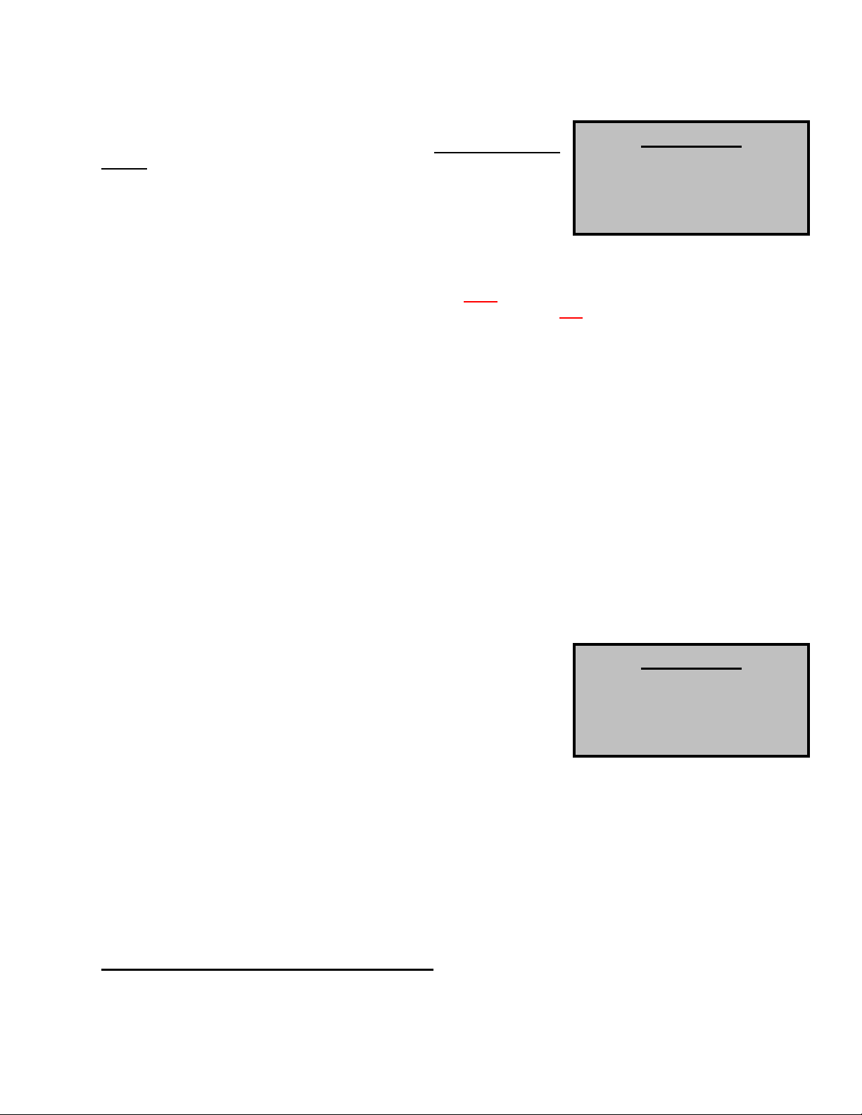
Vertically Vented Furnaces
1. Use single wall or double wall (Type B) vent pipe of a diameter listed
in the following table for the appropriate model.
2. Maximize the height of the vertical run of vent pipe. A minimum of
five (5) feet (1.5m) of vertical pipe is required. The top of the vent
pipe must extend at least two (2) feet (0.61m) above the highest point
on the roof. Use Listed Type B vent for external runs. An approved
weatherproof vent cap must be installed on the vent termination.
3. Horizontal runs should be pitched upward ¼ in. per foot (21mm/m) and should be supported at three
(3) foot (1m) maximum intervals.
4. Design vent pipe runs to minimize the use of elbows. Each 90⁰ elbow is equivalent to five (5) feet
(1.5m) of straight vent pipe.
5. Vent pipe should not be run through unheated spaces. If such runs cannot be avoided, insulate the
vent pipe to prevent condensation. Insulation should be a minimum of ½ in. (12.7mm) thick foil faced
fiberglass minimum of 1½ # density.
6. Dampers must not be used in vent piping runs, as spillage of flue gases into the occupied space
could result.
7. Vent connectors serving Category 1 heaters must not be connected into any portion of a mechanical
draft system operating under positive pressure.
National Fuel Gas Code Venting Pipe requirement
75,000-149,999 Use 5-inch pipe
150,000-400,000 Use 6-inch pipe
8
Furnace Only Modules must be
installed in a positive pressure
airstream. Do not install in a
duct on the suction side of a
Vertical Venting
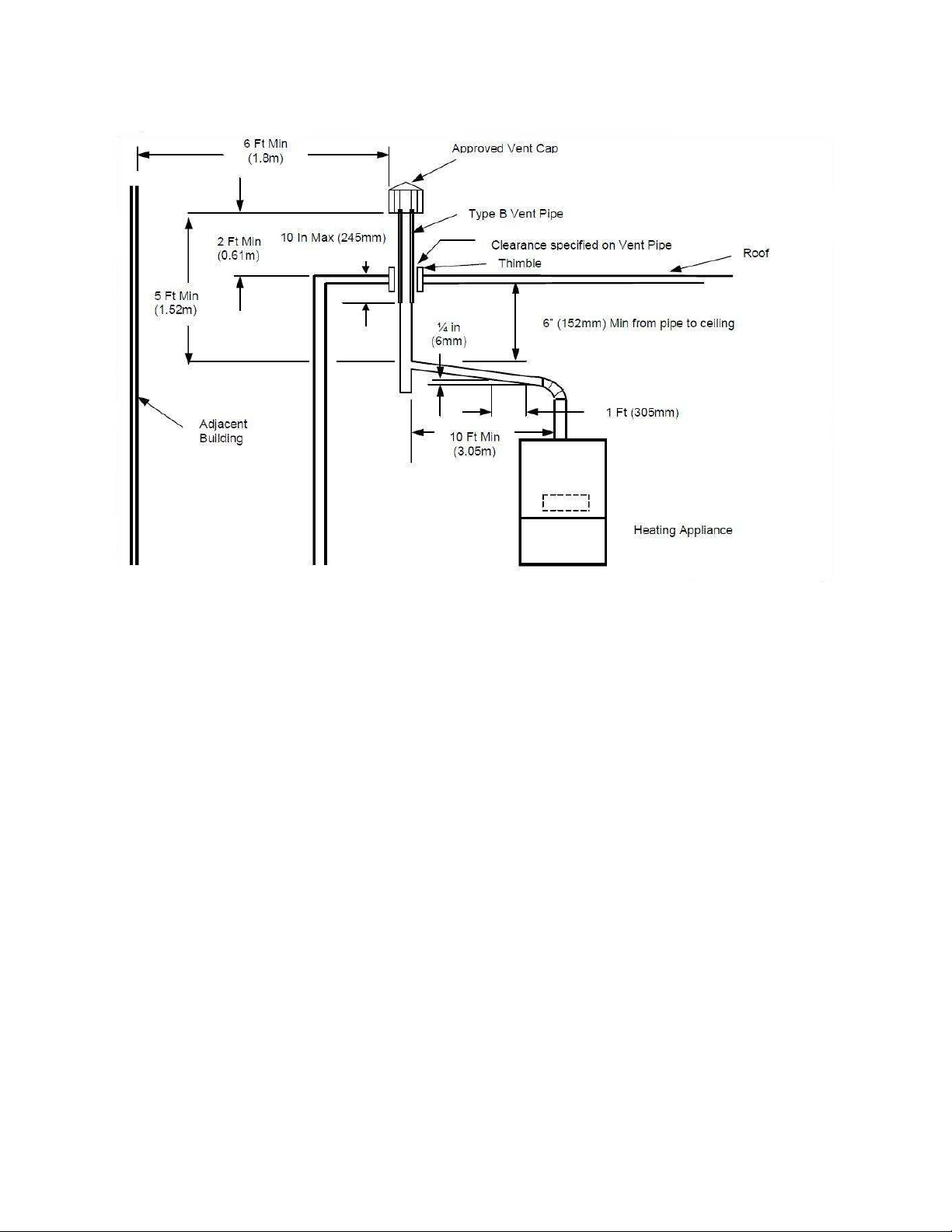
Horizontally Vented Furnaces – Category III
Horizontal vent systems terminate horizontally (sideways)
WARNING: Do not use Type B vent within a building on horizontally vented units.
1. All vent pipe joints must be sealed to prevent leakage. Follow the instructions provided with the
approved venting materials.
2. The total equivalent length of vent pipe must not exceed 50 ft. (15.25m). Equivalent length is the total
length of straight sections, plus 5 ft. (1.52m) for each 90⁰ elbow and 2.5 ft. (0.76m) for each 45⁰
elbow.
3. The vent system must also be installed to prevent collection of condensate. Horizontal runs should be
pitched upward ¼ in. per foot (21mm/m) and should be supported at three (3) foot (1m) maximum
intervals.
4. Insulate vent pipe exposed to cold air or routed through unheated areas. Insulate vent pipe runs
longer than 10 ft. (3m). Insulation should be a minimum of ½ in. (12mm) thick foil faced fiberglass of 1
½ # density. Maintain 6 in. (152mm) clearance between vent pipe and combustible materials.
5. An approved Breidert Type L, Field Starkap or equivalent vent cap must be provided. Vent cap inlet
diameter must be the same as the vent pipe diameter.
6. The vent terminal must be at least 12 in. (305mm) from the exterior wall that it passes through to
prevent degradation of building material by flue gases.
7. The vent terminal must be located at least 12 in. (305mm) above grade, or in snow areas, at least 3
ft. (1m) above snow line to prevent blockage.
8. The vent terminal must be installed with a minimum horizontal clearance of 4 ft. (1.2m) from electric
meters, gas meters, regulators or relief equipment.
9
10
Through-the-wall vents shall not terminate over public walkways or over an area where condensate or
vapor could create a nuisance or hazard. Provide vent termination clearances to building or structure
features as follows:
Structure Minimum Clearance
Door, Window or gravity inlet 4 ft. (1.2 m) below
4 ft. (1.2 m) horizontally
1 ft. (305 mm) above
Forced air inlet within 10 ft. (3m) 3 ft. (.91 m) above
Adjoining building or parapet 6 ft. (1.8 m)
Adjacent public walkways 7 ft. (2.1 m) above grade
Horizontal Venting
EACH APPLIANCE MUST HAVE ITS OWN INDIVIDUAL VENT PIPE AND TERMINAL. Do not connect
vent system from horizontally vented units to other vent systems or a chimney
11
Gas
Installation of gas piping must conform with local building codes, or in the absence of local codes, with the
National Fuel Gas Code, ANSI Z223.1 (NFPA 54) – latest edition. In Canada, installation must be in
accordance with CAN/CGA-B149.1 for natural gas units and CAN/CGA-B149.2 for propane units.
WARNING: INLET GAS PRESSURE MUST NOT EXCEED 14 IN. W.C. SEE UNIT
RATING PLATE FOR PROPER GAS SUPPLY PRESSURE AND GAS TYPE.
1. Always disconnect power
before working on or near a
heater. Lock and tag the
disconnect switch or breaker to
prevent accidental power up.
2. Piping to the unit should
conform with local and national
requirements for type and
volume of gas handled, and
pressure drop allowed in the
line. Refer to the Gas
Engineer’s Handbook for gas
line capacities.
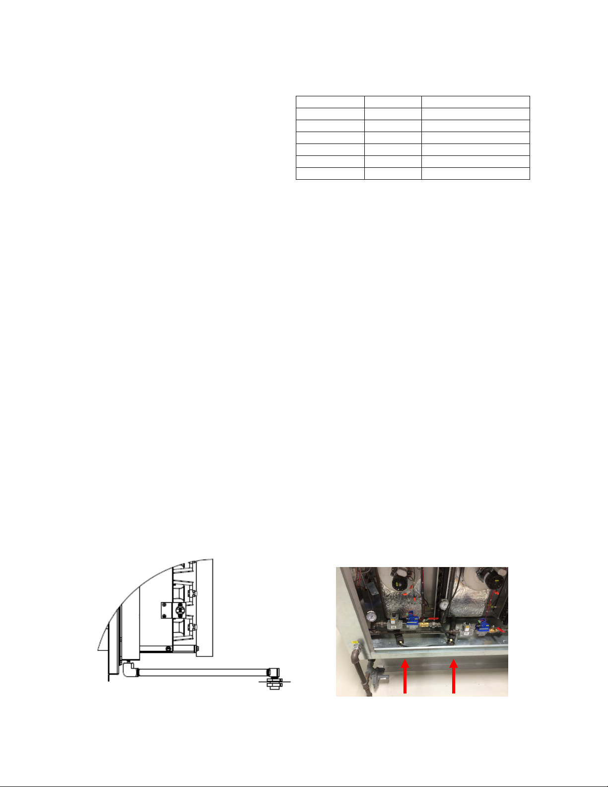
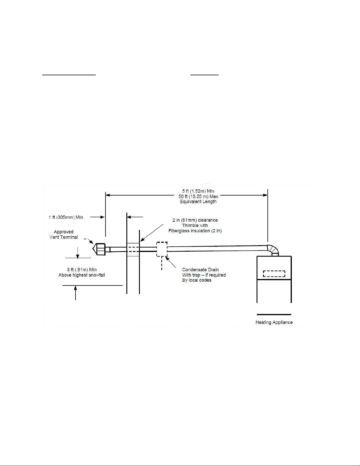
3. The incoming pipe near the
heater should be sized to
match the connection on the
outside of the unit. Unit inlet sizes are shown in the table to the right. Avoid multiple taps in the
gas supply so the unit has a steady supply of gas at all times.
4. Install a ground joint union with brass seat and a manual shut-off valve external to the unit casing,
as shown below, adjacent to the unit for emergency shut-off and easy servicing of controls.
5. Provide a sediment trap, as shown below, before each unit and where low spots in the pipe line
cannot be avoided.
6. Blow out the gas line to remove debris before making connections. Purge line to remove air
before attempting to start unit. Purging of air from gas lines should be performed as described in
ANSI Z223.1-latest edition “National Fuel Gas Code”, or in Canada in CAN/CGA-B149.
7. All field gas piping must be
pressure/leak tested prior to
unit operation. Use a noncorrosive bubble forming
solution or equivalent for
leak testing. The heater
and its individual shut-off
valve must be disconnected
from the gas supply piping
system during any pressure
testing of that system at test
pressures in excess of ½ psi. The heater must be isolated from the gas supply piping system by
closing its individual manual shutoff valve during any pressure testing of the gas supply piping
system at test pressures equal to or less than ½ psi.
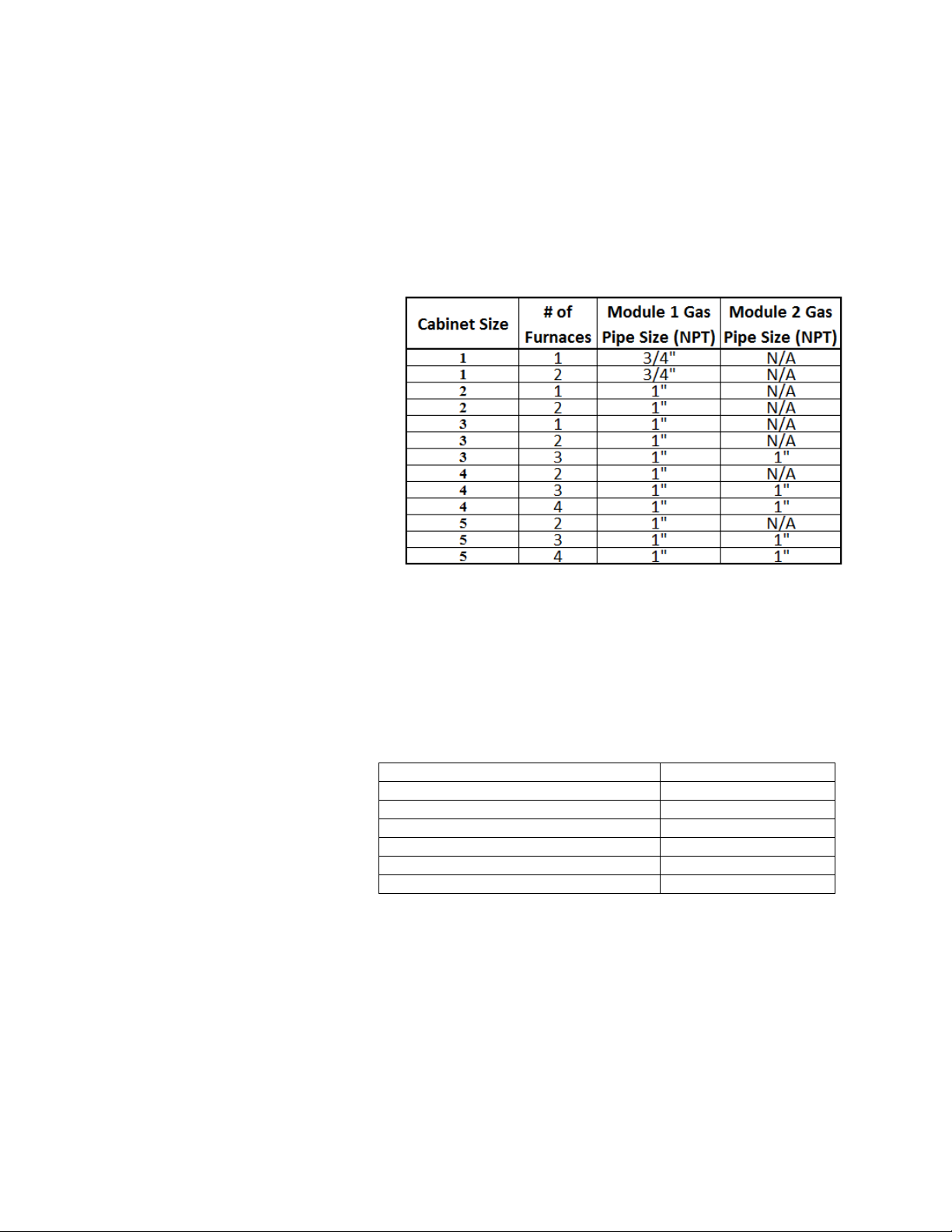
Gas Pressure Table
Gas Pressure Type Gas Pressure
Inlet Pressure - Natural Gas 7 in. w.c. – 14 in. w.c.
Inlet Pressure - Propane 11 in. w.c. – 14 in. w.c.
Max. Manifold Pressure - Natural Gas 3.5 in. w.c. maximum
Max. Manifold Pressure - Propane 10 in. w.c. maximum
Min. Manifold Pressure - Natural Gas 0.15 in. w.c. minimum
Min. Manifold Pressure - Propane 0.75 in. w.c. minimum

12
8. This unit requires a constant 7 in. w.c. minimum natural gas supply, (LP should be 11 in. w.c.
WARNING!!
NOTICE
minimum) when the unit is operating at maximum gas flow. If the gas supply exceeds 14 in.
w.c. it will damage the internal valve
components, and if it is below 7 in. w.c., the
heater may not perform to specifications.
Refer to the heater rating
plate for determining the
minimum gas supply
pressure for obtaining the
maximum gas capacity for
which this heater is specified.
Gas Connection Diagram
Electrical
Before connecting power to the heater, read and understand
this entire section of this document. As-built wiring diagrams
are furnished with each fan by the factory, and are attached
to the door of the unit.
Electrical wiring and connections should be done in
accordance with local ordinances and the National Electric
Code, ANSI/NFPA70. Be sure the voltage and phase of the
power supply and the wire amperage capacity is in accordance with the motor nameplate. For additional
safety information refer to AMCA publication 410-96, Recommended Safety Practices for Users and
Installers of Industrial and Commercial Fans.
Disconnect power before
installing or servicing fan. High
voltage electrical input is
needed for this equipment. This
work should be performed by a
qualified electrician.
1. Always disconnect power before working on or near a
heater. Lock and tag the disconnect switch or breaker
to prevent accidental power up.
2. An electrical drop containing the motor power wiring is
shipped with every fan. The electrical drop should be
brought through one of the conduit openings located in
the base of the unit, run through the curb, and
connected to a junction box inside the building.
3. A dedicated branch circuit should supply the motor
circuit with short circuit protection
according to the National Electric
Code. This dedicated branch
should be run to the junction box
mentioned above and connected
as shown in a following illustration
labeled “Fan to Building Wiring
Connection”.
4. Make certain that the power
source is compatible with the
requirements of your equipment.
The heater nameplate identifies
Copper Wire Ampacity
Wire Size AWG Maximum Amps
14 20
12 25
10 30
8 40
6 55

13
the proper phase and voltage of the motor.
5. Units shipped with an optional remote panel have two electrical circuit drops. It is important to
run the motor wires in a separate conduit from the remote control wiring. The DC wires from the
unit temperature controller, located in the control drop, should either be shielded cable or be run
in a separate conduit.
6. Before connecting heater to the building power source, verify power line wiring is de-energized.
7. Secure the power cables to prevent contact with sharp objects.
8. Do not kink power cable and never allow the cable to come in contact with oil, grease, hot
surfaces or chemicals.
9. Before powering up the heater, check fan wheel for free rotation and make sure that the interior of
the heater is free of loose debris or shipping materials.
10. If any of the original wire supplied with the heater must be replaced, it must be replaced with type
TW wire or equivalent.
PSC (Permanent Split Capacitor) Motor Speed Control
Some single phase direct drive fans contain speed controls that regulate the amount
of voltage going to the motor. Specific PSC motors must be used in conjunction with
speed controls. The speed control has a knob with an off position, and high to low
range. At high speed, the speed control allows all of the line voltage to pass right to
the motor.
A minimum speed adjustment is provided to allow independent control of the
minimum speed setting. Minimum speed adjustment ensures motor runs with
sufficient torque to prevent stalling. To adjust this:
1) Motor must be in actual operating conditions to achieve proper speed
adjustment. Motor will not slow down unless proper load is applied.
2) Turn main control knob to lowest speed position.
3) Locate and adjust minimum speed setting and adjust with small screw driver. This can be found
under the speed control faceplate. (rotate clockwise to decrease minimum speed; counterclockwise to increase minimum speed).
4) Motor will now operate from this preset minimum speed to full speed.
The lowest minimum voltage that may be applied to these motors is 65VAC. Running lower
voltages to the motor can cause premature failure and overheating problems.
ECM (Electronically Controlled Motor) Speed Control
ECM motors and control allows accurate manual adjustment of fan speed.
The benefit of ECM motors is exceptional efficiency, performance, and
motor life.
The control used with ECM motors features a 4 digit LED numerical
display. The blue knob on the control allows the user to set the flow index
with a screwdriver. Twenty seconds later, the display shows the motor
RPM. Then, the display periodically alternates between the flow index and
motor RPM. The flow index has a range of 0 to 100% and is typically linear with motor RPM.
The ECM control requires a 24 VAC input and can locally turn the motor on and off. The motor can be
adjusted between 300 RPM and maximum speed with this control.
NOTE: To adjust the speed of 3 phase direct drive motors, a variable frequency
drive is required.

14
Electric Cabinet Heater
On units shipped with an optional electric cabinet heater, ensure that the heater is wired to a separate
120V, 15 amp input, the thermostat sensing bulb is mounted correctly in the control vestibule where the
heater is located, and the thermostat set to 0 Degrees Fahrenheit.
Motorized Intake Damper
On units shipped with the optional motorized intake damper, a power transformer is supplied with the unit
if the main incoming voltage is greater than 120V. The damper motor is automatically energized when
the main disconnect switch is in the ON position. No external wiring to the damper motor is required.
Remote Control Panel
On units shipped with the optional remote control panel, an electrical drop containing the panel wiring is
provided with the heater. There is a terminal strip inside the remote panel that matches the terminals in
the heater unit. The remote panel should be wired as shown below.
 Loading...