

FloAire FKB-INLINE User Manual
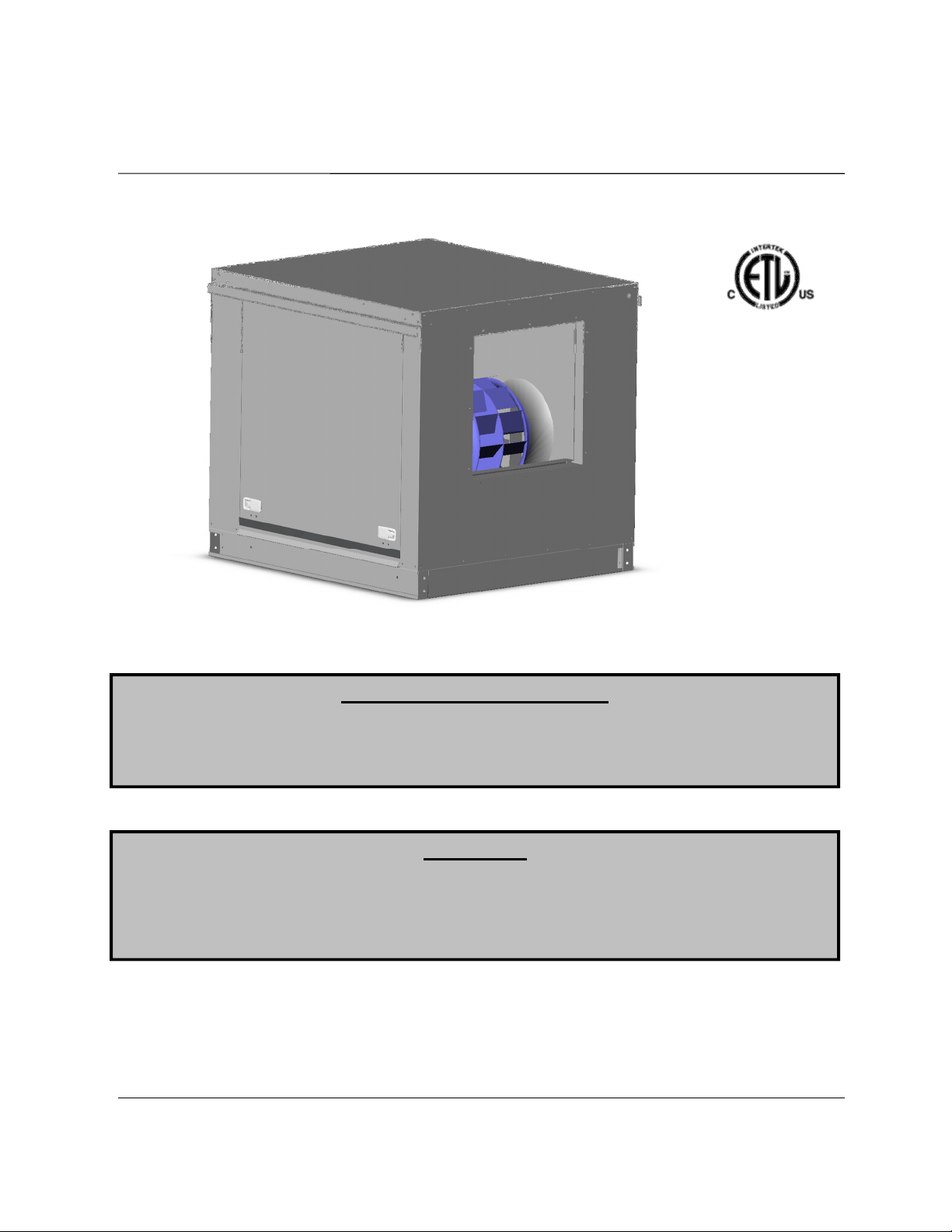
PCU
and Inline
Exhaust Fan
Installation, Operation, and Maintenance Manual
Save these instructions
RECEIVING AND INSPECTION
WARNING!!
Upon receiving unit, check for any interior and exterior damage, and if found, report it
immediately to the carrier. Also check that all accessory items are accounted for and are
damage free. Turn the blower wheel by hand to verify free rotation and check the damper (if
supplied) for free operation.
Installation of this ventilator should only be performed by a qualified professional who has
read and understands these instructions and is familiar with proper safety precautions.
Improper installation poses serious risk of injury due to electric shock, contact with rotating
equipment, and other potential hazards. Read this manual thoroughly before installing or
servicing this equipment. ALWAYS disconnect power prior to working on fan.
. This document is the property of the owner of this equipment and is
required for future maintenance. Leave this document with the owner when installation or
service is complete.
August 2014 Rev. 6
A0017475

TABLE OF CONTENTS
WARRANTY .................................................................................................................................................. 3
LISTINGS ...................................................................................................................................................... 4
INSTALLATION ............................................................................................................................................. 4
Mechanical ................................................................................................................................................ 4
Site Preparation .................................................................................................................................... 4
Roof Mounting ...................................................................................................................................... 4
Indoor Mounting .................................................................................................................................... 4
Curb and Ductwork ............................................................................................................................... 5
Recommended Discharge Ductwork Size ............................................................................................ 5
Typical Roof Mount KB Installation with PCU ...................................................................................... 6
Typical Indoor KB Installation with PCU ............................................................................................... 6
Typical Roof Mount KB-INLINE Installation ......................................................................................... 7
Typical Indoor KB-INLINE Installation .................................................................................................. 7
Copper Wire Ampacity ......................................................................................................................... 8
Fan to Building Wiring Connection ....................................................................................................... 9
OPERATION ............................................................................................................................................... 10
Start Up ................................................................................................................................................... 10
Special Tools Required ...................................................................................................................... 10
Start Up Procedure ............................................................................................................................. 10
Pulley Adjustment (Belt Drive Fans) ................................................................................................... 11
Pulley Setscrew Torque ..................................................................................................................... 11
Pulley Alignment ................................................................................................................................. 11
Proper Belt Tension ............................................................................................................................ 11
Pulley Combination Chart for 3600 RPM Motors ............................................................................... 12
Pulley Combination Chart for 1800 RPM Motors ............................................................................... 13
Troubleshooting ...................................................................................................................................... 14
Troubleshooting Chart ........................................................................................................................ 14
MAINTENANCE .......................................................................................................................................... 15
General Maintenance ............................................................................................................................. 15
2 weeks after startup .............................................................................................................................. 15
Every 3 months ....................................................................................................................................... 15
Yearly ...................................................................................................................................................... 15
Job Information ................................................................................................................................... 16
Fan Unit Information ........................................................................................................................... 16
Maintenance Record .......................................................................................................................... 16
Factory Service Department ............................................................................................................... 16
2

WARRANTY
This equipment is warranted to be free from defects in materials and workmanship, under normal use and
service, for a period of 12 months from date of shipment. This warranty shall not apply if:
1. The equipment is not installed by a qualified installer per the MANUFACTURER’S installation
instructions shipped with the product,
2. The equipment is not installed in accordance with federal, state and local codes and regulations,
3. The equipment is misused or neglected,
4. The equipment is not operated within its published capacity,
5. The invoice is not paid within the terms of the sales agreement.
The MANUFACTURER shall not be liable for incidental and consequential losses and damages
potentially attributable to malfunctioning equipment. Should any part of the equipment prove to be
defective in material or workmanship within the 12-month warranty period, upon examination by the
MANUFACTURER, such part will be repaired or replaced by MANUFACTURER at no charge. The
BUYER shall pay all labor costs incurred in connection with such repair or replacement. Equipment shall
not be returned without MANUFACTURER’S prior authorization and all returned equipment shall be
shipped by the BUYER, freight prepaid to a destination determined by the MANUFACTURER.
3

LISTINGS
The KB fan is ETL listed to standard UL-705 (electrical). The KB fan complies with UL-762 and CSA Std
C22.2, No.113 listing when attached to a multi-pass air cleaning unit and installed in accordance with
National Fire Protection Association Standard “NFPA 96, Standard for Ventilation Control and Fire
Protection of Commercial Cooking Operations”.
KB-INLINE is ETL listed and complies with UL705 (electrical) and UL762 and CSA Std C22.2, No 113.
INSTALLATION
It is imperative that this unit is installed and operated with the designed airflow and electrical supply in
accordance with this manual. If there are any questions about any items, please call the service
department at 1-866-784-6900 for warranty and technical support issues.
Mechanical
WARNING: DO NOT RAISE VENTILATOR BY THE HOOD, BLOWER OR MOTOR
SHAFT, OR BEARINGS – USE LIFTING LUGS PROVIDED OR A SLING
Site Preparation
1. Provide clearance around installation site to safely rig and lift equipment into its final position.
Supports must adequately support equipment. Refer to manufacturer’s estimated weights.
2. Consider general service and installation space when locating unit.
3. Locate unit close to the space it will serve to reduce long, twisted duct runs.
4. The fan discharge must be located at least 10 feet away from any supply intakes. The fan
discharge shall be located in accordance with the applicable building code provisions.
5. The PCU is designed to operate in a negative pressure environment. Be sure to install the KB
unit after a PCU. This will also keep the fan cleaner during operation.
Roof Mounting
1. Ventilators are designed for installation atop a prefabricated or factory built roof curb. Follow
manufacturer’s instructions for proper curb installation.
2. Secure ventilator curb through vertical portion of the ventilator base assembly flange using a
minimum of eight (8) lug screws, anchor bolts, or other suitable fasteners (not furnished).
3. Before connecting fan motor to power source verify power line wiring is de-energized.
4. Connect power supply wiring to the motor as indicated on the motor nameplate or terminal box
cover. Make certain that the power source is compatible with the requirements of your
equipment.
5. Before powering up fan check ventilator wheel for free rotation.
6. Check all fasteners for tightness.
Indoor Mounting
1. Ventilators are designed for installation in indoor or inline installations.
2. Optional uni-strut bars can be ordered to suspend the unit from a roof structure.
3. 18 inches of clearance are required on all sides of the ventilator or the unit must be wrapped
with clearance reducing grease rated insulation.
4. Before connecting fan motor to power source verify power line wiring is de-energized.
5. Connect power supply wiring to the motor as indicated on the motor nameplate or terminal box
cover. Make certain that the power source is compatible with the requirements of your
equipment.
6. Before powering up fan check ventilator wheel for free rotation.
7. Check all fasteners for tightness.
4
Curb and Ductwork
This fan was specified for a specific CFM and static
pressure. The ductwork attached to this unit will
significantly affect the airflow performance.
Flexible ductwork and square elbows should not be
used. Also, transitions and turns in ductwork near
the fan inlet will cause system effect and will
drastically increase the static pressure and reduce
airflow. Follow SMACNA guides and
recommendations for the remaining duct run.
Fans designed for rooftop installation should be
installed on a prefabricated or factory built roof curb. Follow curb manufacturer’s instructions for proper
curb installation. Curbs should be connected to structural roof members with at least four (3) lug screws,
anchor bolts, or other suitable fasteners (not furnished) per curb flange. Curb flanges should be caulked
to roof.
The fan should be installed on a curb and/or rail elevated not less than 14” above any surface when
installed outdoors. Be sure duct connection and fan outlet are properly aligned and sealed. Secure fan
to curb through vertical portion of the ventilator base assembly flange using a minimum of eight (8) lug
screws, anchor bolts, or other suitable fasteners (not furnished). Shims may be required depending upon
curb installation and roofing material. Check all fasteners for tightness. The diagrams below show
different mechanical installation configurations.
Ensure duct connections are properly aligned and sealed. When this fan unit is used in commercial
grease ductwork, the ductwork connections must be FULLY WELDED to the fan. Clearance ratings of
ductwork connected to the unit apply to the fan as well. Ductwork must be listed or installed in
accordance with the IMC.
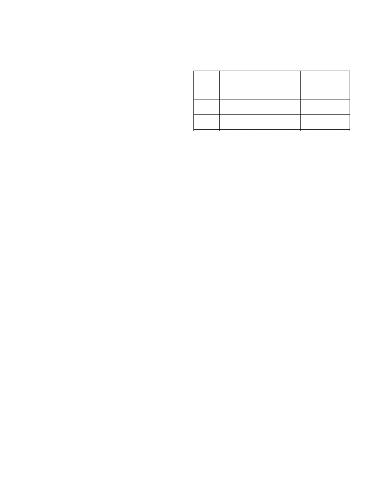
Recommended Discharge Ductwork Size
Blower
Size
10 14 in. x 14 in.
14 20 in. x 20 in.
18 24 in. x 24 in. 33 in. 86 in.
20 26 in. x 26 in. 37 in. 108 in.
Min.
Rectangular
Duct Size
Min.
Round
Duct
Diameter
19 in. 48 in.
26 in. 72 in.
Min. Straight
Duct Length
5
 Loading...