

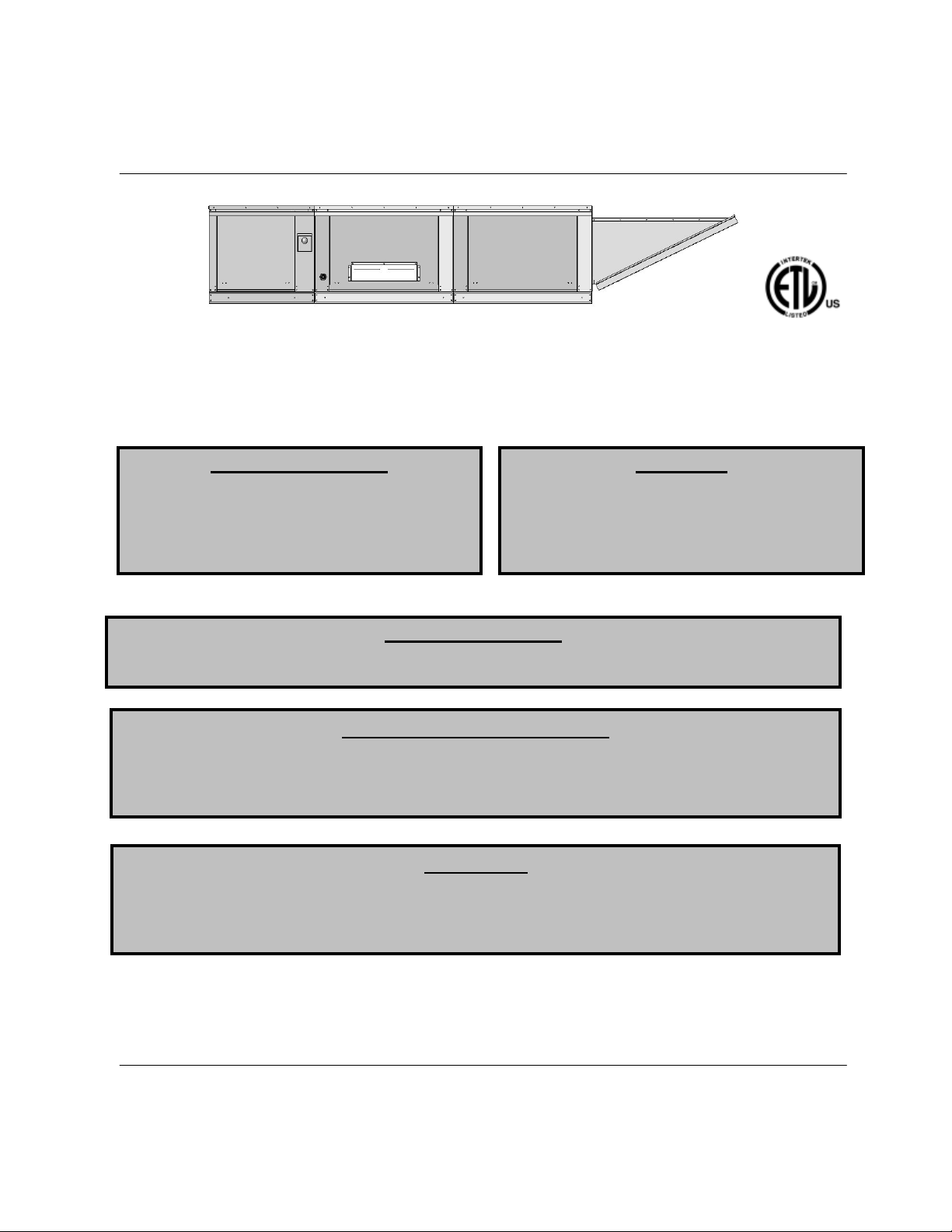
FloAire F-D User Manual
FOR YOUR SAFETY
Standard and Modular
Direct Fired
Re-Circulating
Heater
s
Installation, Operation, and Maintenance Manual
Save these instructions
RECEIVING AND INSPECTION
WARNING!!
FOR YOUR SAFETY
WARNING
Modular Direct Fired Re-Circulating Heater
1. Open windows.
2. Don’t touch electrical switches.
3. Extinguish any open flames.
4. Immediately call your gas supplier.
The use and storage of gasoline or other flammable vapors and liquids in open containers in the
vicinity of this appliance is hazardous.
If you smell gas:
On heaters that recirculate room air, outside
ventilation air must be provided in accordance
with the information shown on the heater name
plate.
Upon receiving unit, check for any interior and exterior damage, and if found, report it
immediately to the carrier. Also check that all accessory items are accounted for and are
damage free. Turn the blower wheel by hand to verify free rotation and check the damper (if
supplied) for free operation.
Improper installation, adjustment, alteration, service or maintenance can cause property
damage, injury or death. Read the installation, operating and maintenance instructions
thoroughly before installing or servicing this equipment. ALWAYS disconnect power and gas
prior to working on heater.
. This document is the property of the owner of this equipment and is
required for future maintenance. Leave this document with the owner when installation or
service is complete.
August 2013 Rev. 1
A0020936


TABLE OF CONTENTS
WARRANTY ...................................................................................................................................................................................... 4
INSTALLATION ................................................................................................................................................................................. 5
Mechanical ................................................................................................................................................................................... 5
Site Preparation ...................................................................................................................................................................... 5
Assembly ................................................................................................................................................................................ 6
Curb and Ductwork ................................................................................................................................................................. 6
Indoor (INLINE) Installation ..................................................................................................................................................... 7
Roof Mount Installation ........................................................................................................................................................... 7
Gas .............................................................................................................................................................................................. 8
Gas Connection Sizes ............................................................................................................................................................ 8
Gas Pressure Table ................................................................................................................................................................ 8
Gas Connection Diagram ........................................................................................................................................................ 8
Electrical ...................................................................................................................................................................................... 9
Copper Wire Ampacity ............................................................................................................................................................ 9
PSC (Permanent Split Capacitor) Motor Speed Control ........................................................................................................ 10
ECM (Electronically Controlled Motor) Speed Control ........................................................................................................... 10
Motorized Intake Damper ...................................................................................................................................................... 10
Electric Cabinet Heater ......................................................................................................................................................... 10
Remote Control Panel ........................................................................................................................................................... 11
Fan to Building Wiring Connection ........................................................................................................................................ 11
Start Up ...................................................................................................................................................................................... 12
Special Tools Required ......................................................................................................................................................... 12
Start Up Procedure ............................................................................................................................................................... 12
Pilot Adjustment .................................................................................................................................................................... 12
Pilot Assembly ...................................................................................................................................................................... 12
Main Burner Adjustment ........................................................................................................................................................ 13
Maxitrol M511 and M611 Low Fire Bypass Screw ................................................................................................................. 13
Heater Start Up Summary ..................................................................................................................................................... 14
Final Start Up Procedure ....................................................................................................................................................... 15
Pulley Adjustment ................................................................................................................................................................. 15
Pulley Alignment ................................................................................................................................................................... 15
Proper Belt Tension .............................................................................................................................................................. 15
Pulley Setscrew Torque ........................................................................................................................................................ 15
Pulley Combination Chart ..................................................................................................................................................... 16
Sequence of Operation ............................................................................................................................................................... 17
Flame Safety Control ............................................................................................................................................................ 17
Air Flow Switch ..................................................................................................................................................................... 17
DC Flame Signal ................................................................................................................................................................... 17
Modulating Gas System ........................................................................................................................................................ 18
High Temperature Limit......................................................................................................................................................... 18
Operation Summary .............................................................................................................................................................. 18
Optional Remote Panel Circuit .............................................................................................................................................. 19
Re-Circulating Control Options ........................................................................................................................................................ 20
Manual Positioning Control (Potentiometer) .......................................................................................................................... 20
Two Position Control ............................................................................................................................................................. 20
Static Pressure Control (Photohelic) ..................................................................................................................................... 21
A306 Outdoor Sensor ........................................................................................................................................................... 22
Building Signal Damper Control ............................................................................................................................................ 22
Components .................................................................................................................................................................................... 23
Remote Panel Option ............................................................................................................................................................ 24
Troubleshooting ............................................................................................................................................................................... 25
Airflow Troubleshooting Chart ............................................................................................................................................... 25
Burner Troubleshooting Chart ............................................................................................................................................... 26
Remote Panel Troubleshooting Chart ................................................................................................................................... 27
Troubleshooting Flowcharts .................................................................................................................................................. 28
MAINTENANCE .............................................................................................................................................................................. 29
General Maintenance ................................................................................................................................................................. 29
2 weeks after startup .................................................................................................................................................................. 30
Every 3 months .......................................................................................................................................................................... 30
Filter Quantity Chart .............................................................................................................................................................. 30
Yearly ......................................................................................................................................................................................... 31
Burner Orifice Drill Size ........................................................................................................................................................ 31
Start-Up and Maintenance Documentation ................................................................................................................................. 32
Job Information ..................................................................................................................................................................... 32
Heater Information ................................................................................................................................................................ 32
Maintenance Record ............................................................................................................................................................. 32
Factory Service Department.................................................................................................................................................. 32
3

WARRANTY
This equipment is warranted to be free from defects in materials and workmanship, under normal use and
service, for a period of 12 months from date of shipment. This warranty shall not apply if:
1. The equipment is not installed by a qualified installer per the MANUFACTURER’S installation
instructions shipped with the product,
2. The equipment is not installed in accordance with federal, state and local codes and regulations,
3. The equipment is misused or neglected,
4. The equipment is not operated within its published capacity,
5. The invoice is not paid within the terms of the sales agreement.
The MANUFACTURER shall not be liable for incidental and consequential losses and damages
potentially attributable to malfunctioning equipment. Should any part of the equipment prove to be
defective in material or workmanship within the 12-month warranty period, upon examination by the
MANUFACTURER, such part will be repaired or replaced by MANUFACTURER at no charge. The
BUYER shall pay all labor costs incurred in connection with such repair or replacement. Equipment shall
not be returned without MANUFACTURER’S prior authorization and all returned equipment shall be
shipped by the BUYER, freight prepaid to a destination determined by the MANUFACTURER.
4
INSTALLATION
CLEARANCES
It is imperative that this unit is installed and operated with the designed airflow, gas, and electrical supply
in accordance with this manual. If there are any questions about any items, please call the service
department at 1-866-784-6900 for warranty and technical support issues.
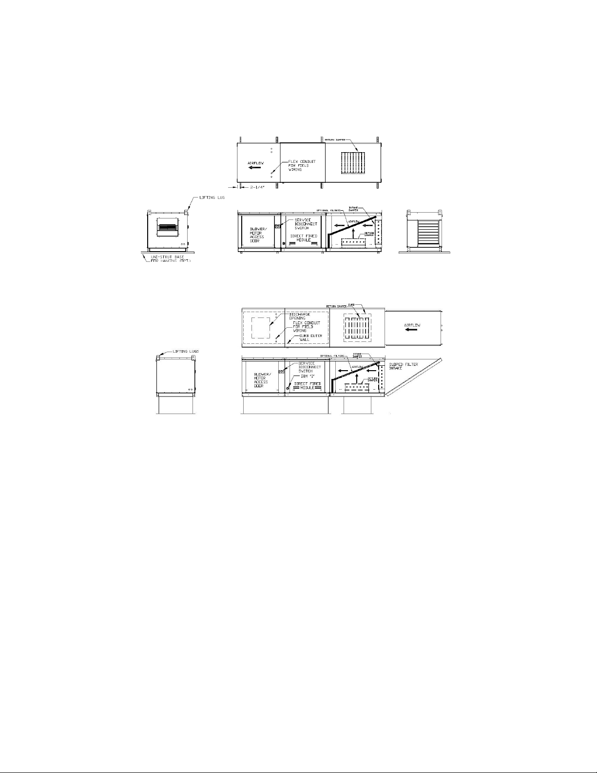
Mechanical
WARNING: DO NOT RAISE VENTILATOR BY THE INTAKE HOOD, BLOWER OR
MOTOR SHAFT, OR BEARINGS – USE LIFTING LUGS PROVIDED OR A SLING
Site Preparation
1) Provide clearance around installation site to safely rig and
lift equipment into its final position. Supports must
adequately support equipment. Refer to manufacturer’s
estimated weights.
2) Consider general service and installation space when
locating unit.
3) Locate unit close to the space it will serve to reduce long,
twisted duct runs.
4) Do not allow air intake to face prevailing winds. Support
unit above ground or at roof level high enough to prevent
precipitation from being drawn into its inlet. The inlet must
also be located at least 10 feet away from any exhaust
vents. The heater inlet shall be located in accordance with the applicable building code
provisions for ventilation air. If in doubt regarding the application, consult the manufacturer. All
ventilation air to the heater shall be ducted directly from the outdoors.
5) Recirculation of room air may be hazardous in the presence of:
a) Flammable solids, liquids and gases
b) Explosive materials (e.g., grain dust, coal dust, gunpowder, etc.)
c) Substances which may become toxic when exposed to heat (e.g., refrigerants, aerosols, etc.)
6) Recirculation is not recommended in uninsulated buildings where outside temperatures fall below
32°F (0°C).
7) Excessive recirculation or insufficient ventilation air, which results in inadequate dilution of the
combustion products generated by the heater, may create hazardous concentrations of carbon
dioxide, carbon monoxide, nitrogen dioxide, and other combustion products in the heated space.
8) If gas fork trucks or other fossil fuel powered equipment are utilized in the conditioned area,
additional ventilation requirements for the facility must be addressed separately.
9) If the heater utilizes room sensors for limiting room CO2 concentration:
a) The CO2 control set-point shall be no greater than the maximum allowable room
concentration of 5000 ppm less the sensor’s published accuracy tolerance. The control shall
prevent the CO2 concentration in room air from exceeding 5000 ppm.
b) A minimum of one sensor shall be installed per room served by the heater.
c) When a room area, served by a single heater, does not exceed 10,000 ft2 (929 m2) and height
does not exceed 20 ft (6 m), a duct sensor may be installed in the return air opening of the
heater.
d) Sensors shall be calibrated per the sensor manufacturer’s recommended procedure and
frequency or annually, whichever is more frequent.
e) Sensors shall not be place near sources of CO2.
f) Each heater shall require its own CO2 sensor(s).
The top, back, and front
surfaces of this heater may not
be installed less than 6” from
combustible materials. The
heater base may be installed
on combustible surfaces.
Allow 24” minimum service
clearance on both sides of this
heater.
5
Assembly
Mixing Box Size
Duct Size
1
19 x 15
2
25 x 24
331 x 2
9
5
44 x 44
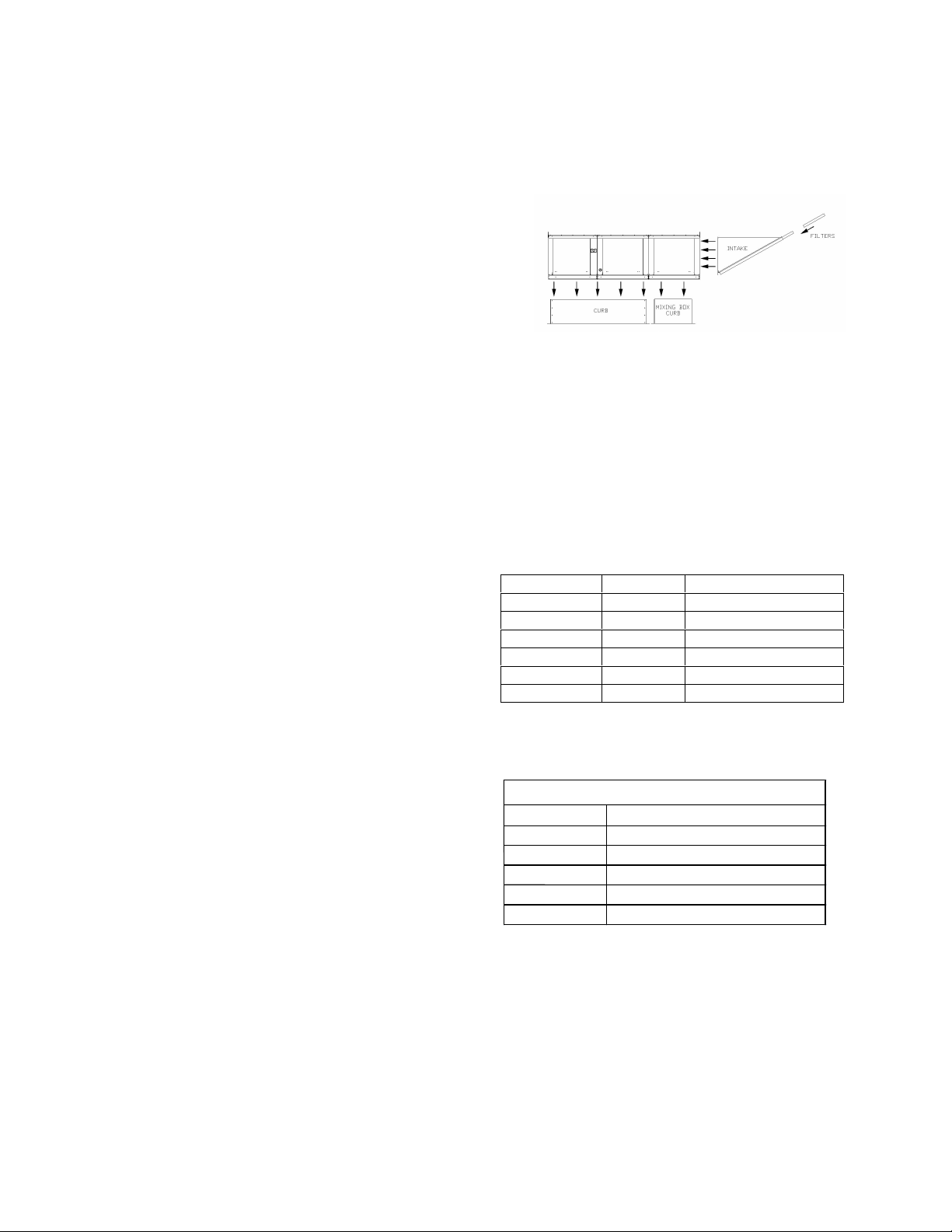
Intakes and curbs are shipped unassembled. Upon unit arrival, follow the following procedure to
assemble the intake to the heater:
1. Apply silicone or weather-proof gasket on the back
side of the flanges of the intake hood or v-bank
intake.
2. Screw the flanges of the intake hood or v-bank to
the unit with the supplied sheet metal screws.
Place caulk on the outside of the screws to prevent
water leaks. If the unit is a modular unit with a vbank or evaporative cooler section, the v-bank or
evaporative cooler will bolt to the heater with the bolts provided.
Curb and Ductwork
This fan was specified for a specific CFM and static pressure. The ductwork attached to this unit will
significantly affect the airflow performance. Flexible ductwork and square elbows should not be used.
Also, transitions and turns in ductwork near the fan outlet will cause system effect and will drastically
increase the static pressure and reduce airflow. The chart below shows the minimum fan outlet duct
sizes and straight lengths recommended for optimal fan performance. Follow SMACNA guides and
recommendations for the remaining duct run. Fans designed for rooftop installation should be
installed on a prefabricated or factory built roof curb.
Follow curb manufacturer’s instructions for proper
curb installation. The unit should be installed on a
curb and/or rail elevated not less than 20” above
any surface. Be sure duct connection and fan outlet
are properly aligned and sealed. Secure fan to curb
through vertical portion of the ventilator base
assembly flange using a minimum of eight (8) lug
screws, anchor bolts, or other suitable fasteners (not
furnished). Shims may be required depending upon
curb installation and roofing material. Check all
fasteners for tightness. The diagrams below show
different mechanical installation configurations.
Adequate building relief shall be provided so as to not
over pressurize the building when the heating system
is operating at its rated capacity. This can be
accomplished by taking into account, through standard
engineering methods, the structure’s designed
infiltration rate; by providing properly sized relief
openings; or by interlocking a powered exhaust
system; or by a combination of these methods.
Heaters installed with intake ductwork must be purged to replace at least four air changes of the volume
of the intake duct.
If the failure or malfunction of this heater creates a hazard to other fuel burning equipment in the building
(e.g. when the heater is providing make up air to a boiler room), the unit is to be interlocked to open inlet
air dampers or other such devices.
Units being installed in airplane hangars should be installed in accordance with the Standard for Aircraft
Hangars, ANSI/NFPA 409. Units being installed in public garages should be installed in accordance
Recommended Supply Ductwork Sizes
Blower Size Duct Size Straight Duct Length
10 14 x 14 48 in.
12 16 x 16 54 in.
15 20 x 20 72 in.
18 24 x 24 86 in.
20 26 x 26 108 in.
25 32 x 32 168 in.
Recommended Return Ductwork Sizes
4 37 x 34
6
with the Standard for Parking Structures, ANSI/NFPA 88A, or the Standard for Repair Garages,
ANSI/NFPA 88B, and with CAN/CGA B149 Installation Codes.
Indoor (INLINE) Installation
Roof Mount Installation
7
NOTICE
Gas
Installation of gas piping must conform with local building codes, or in the absence of local codes, with the
National Fuel Gas Code, ANSI Z223.1 (NFPA 54) – latest edition. In Canada, installation must be in
accordance with CAN/CGA-B149.1 for natural gas units and CAN/CGA-B149.2 for propane units.
WARNING: INLET GAS PRESSURE MUST NOT EXCEED PRESSURE INDICATED
ON NAMEPLATE. SEE UNIT NAMEPLATE FOR PROPER GAS SUPPLY
PRESSURE AND GAS TYPE.
1. Always disconnect power before working on or near a heater. Lock and tag the disconnect
switch or breaker to prevent accidental power up.
2. Piping to the unit should conform with local and national requirements for type and volume of gas
handled, and pressure drop allowed in the line. Refer to the Gas Engineer’s Handbook for gas
line capacities.
3. The incoming pipe near the heater should be sized to
match the connection on the outside of the unit. Unit inlet
sizes are shown in the table to the right. Avoid multiple
taps in the gas supply so the unit has a steady supply of
gas at all times.
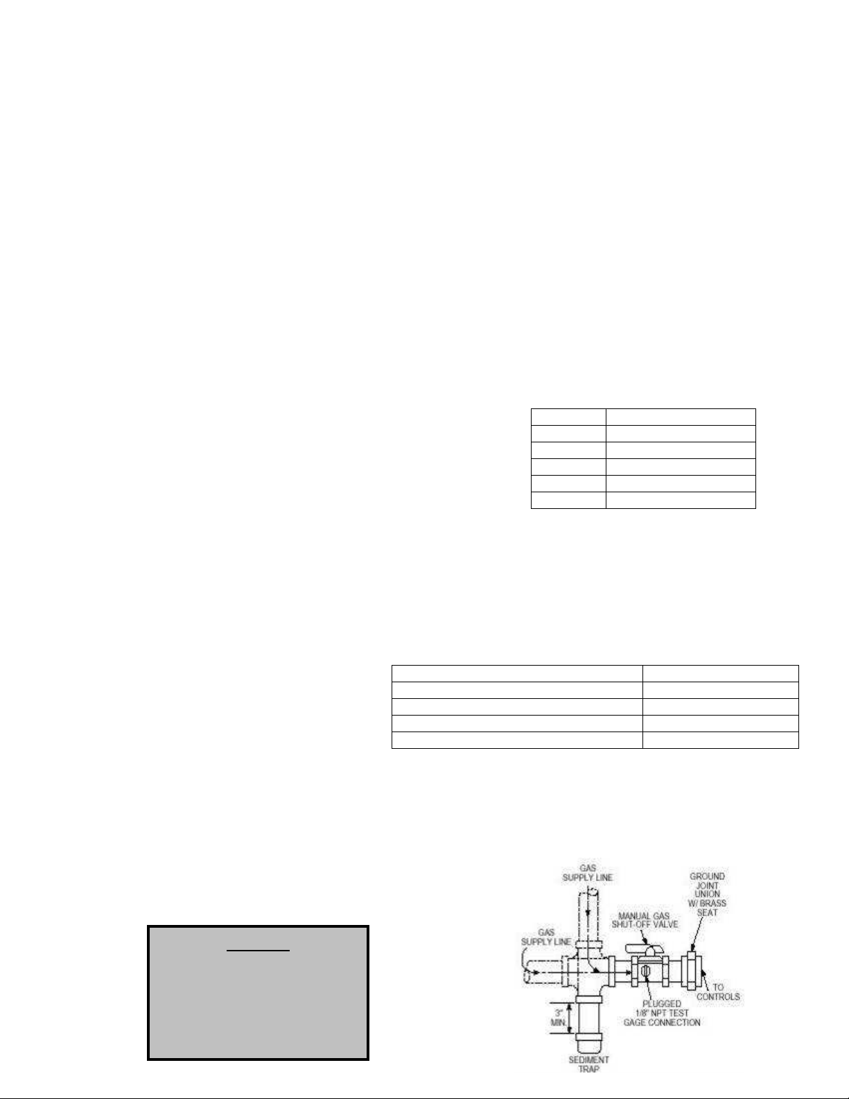
4. Install a ground joint union with brass seat and a manual
shut-off valve external to the unit casing, as shown below,
adjacent to the unit for emergency shut-off and easy
servicing of controls.
5. Provide a sediment trap, as shown below, before each
unit and where low spots in the pipe line cannot be avoided.
6. Blow out the gas line to remove debris before making connections. Purge line to remove air
before attempting to start unit. Purging of air from gas lines should be performed as described in
ANSI Z223.1-latest edition “National Fuel Gas Code”, or in Canada in CAN/CGA-B149.
7. All field gas piping must be pressure/leak tested prior to unit operation. Use a non-corrosive
bubble forming solution or equivalent
for leak testing. The heater and its
individual shut-off valve must be
disconnected from the gas supply
piping system during any pressure
testing of that system at test
pressures in excess of ½ psi. The
heater must be isolated from the gas
supply piping system by closing its
individual manual shutoff valve
during any pressure testing of the gas supply piping system at test pressures equal to or less
than ½ psi.
8. This unit requires a constant 7 in. w.c. minimum
natural gas supply, when the unit is operating at
maximum gas flow. If the gas supply exceeds 14 in.
w.c. (5 psi. for sizes 4-5 housings) it will damage the
internal valve components, and if it is below 7 in.
w.c., the heater may not perform to specifications.
Max. Manifold Pressure - Natural Gas 5 in. w.c. maximum
Max. Manifold Pressure - Propane 2.5 in. w.c. maximum
Gas Pressure Type Gas Pressure
Size 1-3 Inlet Pressure 7 in. w.c. – 14 in. w.c.
Size 4-5 Inlet Pressure 7 in. w.c. – 5 psi.
Gas Connection Sizes
Unit Size Gas Pipe Size (NPT)
Size 1 ¾”
Size 2 1”
Size 3 1”
Size 4 1-1/4”
Size 5 1-1/2”
Gas Pressure Table
Gas Connection Diagram
Refer to the heater rating
plate for determining the
minimum gas supply
pressure for obtaining the
maximum gas capacity for
which this heater is specified.
8
WARNING!!
Electrical
Before connecting power to the heater, read and understand this
entire section of this document. As-built wiring diagrams are
furnished with each fan by the factory, and are attached to the
door of the unit.
Electrical wiring and connections should be done in accordance
with local ordnances and the National Electric Code,
ANSI/NFPA70. Be sure the voltage and phase of the power
supply and the wire amperage capacity is in accordance with the
motor nameplate. For additional safety information refer to AMCA publication 410-96, Recommended
Safety Practices for Users and Installers of Industrial and Commercial Fans.
Disconnect power before
installing or servicing fan. High
voltage electrical input is
needed for this equipment. This
work should be performed by a
qualified electrician.
1. Always disconnect power before working on or near a
heater. Lock and tag the disconnect switch or breaker to
prevent accidental power up.
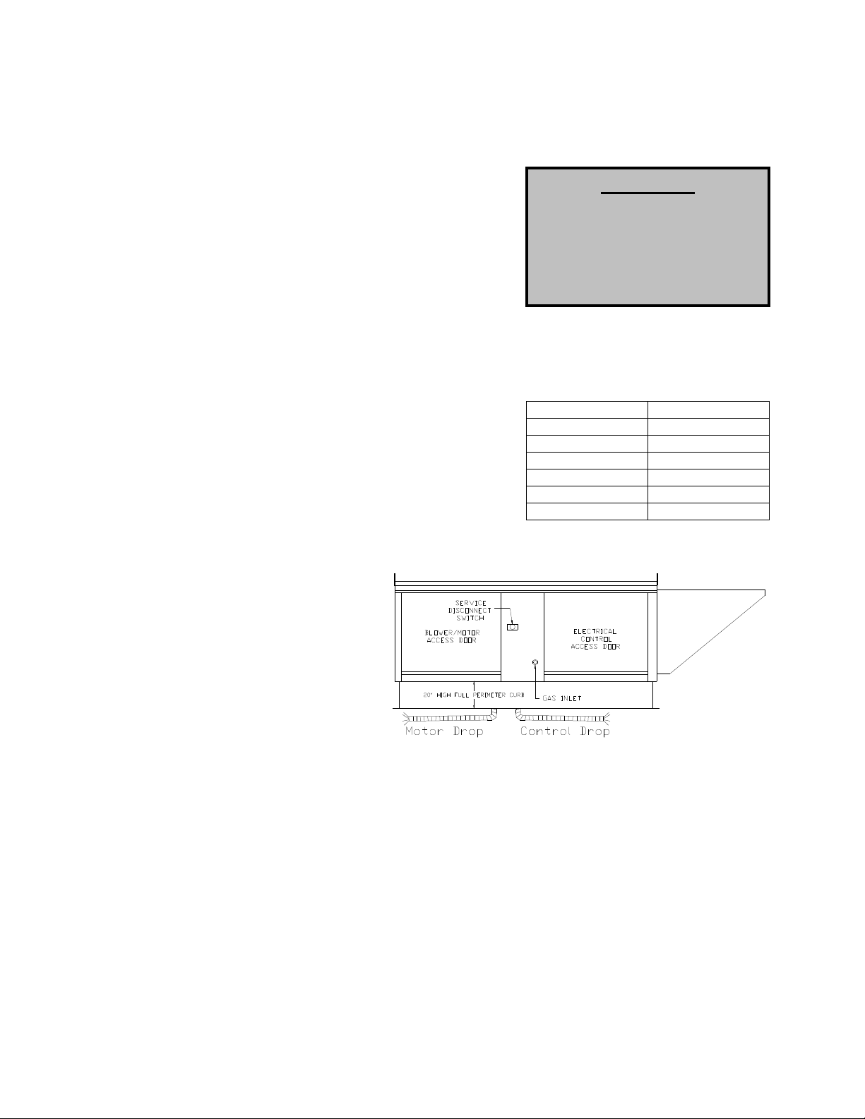
2. An electrical drop containing the motor power wiring is
shipped with every fan. The electrical drop should be
brought through one of the conduit openings located in
the base of the unit, run through the curb, and connected
to a junction box inside the building.
3. A dedicated branch circuit should supply the motor circuit
with short circuit protection according to the National
Electric Code. This dedicated branch should be run to the junction box mentioned above and
connected as shown in a following
illustration labeled “Fan to Building
Wiring Connection”.
4. Make certain that the power source
is compatible with the
requirements of your equipment.
The heater nameplate identifies
the proper phase and voltage of
the motor.
5. Units shipped with an optional
remote panel have two electrical
circuit drops. It is important to run
the motor wires in a separate conduit from the remote control wiring. The DC wires from the unit
temperature controller, located in the control drop, should either be shielded cable or be run in a
separate conduit.
6. Before connecting heater to the building power source, verify power line wiring is de-energized.
7. Secure the power cables to prevent contact with sharp objects.
8. Do not kink power cable and never allow the cable to come in contact with oil, grease, hot
surfaces or chemicals.
9. Before powering up the heater, check fan wheel for free rotation and make sure that the interior of
the heater is free of loose debris or shipping materials.
10. If any of the original wire supplied with the heater must be replaced, it must be replaced with type
THHN wire or equivalent.
Copper Wire Ampacity
Wire Size AWG Maximum Amps
14 15
12 20
10 30
8 50
6 65
4 85
9
10
PSC (Permanent Split Capacitor) Motor Speed Control
Some single phase direct drive fans contain speed controls that regulate the amount
of voltage going to the motor. Specific PSC motors must be used in conjunction
with speed controls. The speed control has a knob with an off position, and high to
low range. At high speed, the speed control allows all of the line voltage to pass
right to the motor.
A minimum speed adjustment is provided to allow independent control of the
minimum speed setting. Minimum speed adjustment ensures motor runs with
sufficient torque to prevent stalling. To adjust this:
1) Motor must be in actual operating conditions to achieve proper speed
adjustment. Motor will not slow down unless proper load is applied.
2) Turn main control knob to lowest speed position.
3) Locate and adjust minimum speed setting and adjust with small screw driver. This can be found
under the speed control faceplate. (rotate clockwise to decrease minimum speed; counterclockwise to increase minimum speed).
4) Motor will now operate from this preset minimum speed to full speed.
The lowest minimum voltage that may be applied to these motors is 65VAC. Running lower
voltages to the motor can cause premature failure and overheating problems.
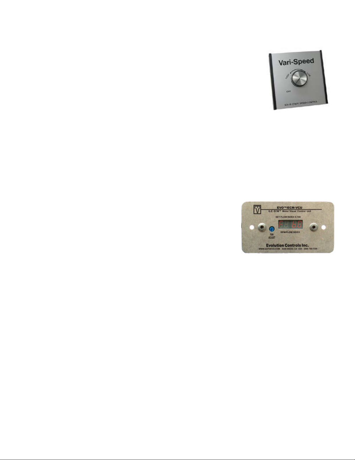
ECM (Electronically Controlled Motor) Speed Control
ECM motors and control allows accurate manual adjustment of fan speed.
The benefit of ECM motors is exceptional efficiency, performance, and
motor life.
The control used with ECM motors features a 4 digit LED numerical
display. The blue knob on the control allows the user to set the flow index
with a screwdriver. Twenty seconds later, the display shows the motor
RPM. Then, the display periodically alternates between the flow index and
motor RPM. The flow index has a range of 0 to 100% and is typically linear with motor RPM.
The ECM control requires a 24 VAC input and can locally turn the motor on and off. The motor can be
adjusted between 300 RPM and maximum speed with this control.
NOTE: To adjust the speed of 3 phase direct drive motors, a variable frequency
drive is required.
Motorized Intake Damper
On units shipped with the optional motorized intake damper, a power transformer is supplied with the unit
if the main incoming voltage is greater than 120V. The damper motor is automatically energized when
the main disconnect switch is in the ON position. No external wiring to the damper motor is required.
Electric Cabinet Heater
On units shipped with an optional electric cabinet heater, ensure that the heater is wired to a separate
120V, 15 amp input, the thermostat sensing bulb is mounted correctly in the control vestibule where the
heater is located, and the thermostat set to 0 Degrees Fahrenheit.
 Loading...