

Page 1
Electrical Controls
Installation, Operation, and Maintenance Manual
Save these instructions. This document is the property of the owner of this equipment and is
required for future maintenance. Leave this document with the owner when installation or
service is complete.
RECEIVING AND INSPECTION
Upon receiving unit, check for any interior and exterior damage, and if found, report it
immediately to the carrier. Also check that all accessory items are accounted for and are
damage free.
WARNING!!
Installation of this control panel should only be performed by a qualified professional who has
read and understands these instructions and is familiar with proper safety precautions.
Improper installation poses serious risk of injury due to electric shock and other potential
hazards. Read this manual thoroughly before installing or servicing this equipment. ALWAYS
disconnect power prior to working on module.
August 2014 Rev. 7
A0023032
Page 2

2
TABLE OF CONTENTS
WARRANTY .................................................................................................................................................. 3
SAFETY INFORMATION .............................................................................................................................. 4
General ................................................................................................................................................. 4
Installation............................................................................................................................................. 4
Control board (ECPM03) Technical Information .................................................................................. 4
INSTALLATION ............................................................................................................................................. 6
Mechanical ................................................................................................................................................ 6
Site Preparation .................................................................................................................................... 6
Assembly .............................................................................................................................................. 6
Utility Cabinet Installation (Typical) ...................................................................................................... 6
Room Sensor Installation ..................................................................................................................... 6
Wall Mount Installation (Optional) ........................................................................................................ 7
Duct Sensor Installation ........................................................................................................................ 7
Electrical ................................................................................................................................................... 7
High Voltage Wiring .............................................................................................................................. 8
Low Voltage Wiring ............................................................................................................................... 9
OPERATION ............................................................................................................................................... 10
Start-Up Procedure ................................................................................................................................. 10
Functionality ............................................................................................................................................ 12
Fan Control ......................................................................................................................................... 12
Hood Lights ........................................................................................................................................ 12
Electric Gas Valve Reset .................................................................................................................... 12
High Temperature Automatic Appliance Shutdown ........................................................................... 12
Appliances Pilot Check Warning: ....................................................................................................... 12
Building Management System (Dry Contact) ..................................................................................... 12
Minimum Room Temperature ............................................................................................................. 13
Self-Cleaning Function (Optional) ...................................................................................................... 13
Fan Proving Interlock (Optional) (i.e. Loss of Load Interlock/Airflow Fault Interlock) ........................ 14
CORE Fire Protection System (Optional) ........................................................................................... 14
PCU Advanced Filter Monitoring (AFM) (Optional) ............................................................................ 14
Electric Gas Valve Follow Fans (optional) .......................................................................................... 14
Shunt Trip Follow Fans (Optional) ...................................................................................................... 14
Dimmable HMI (Optional) ................................................................................................................... 14
CO Sensor Input (Optional) ................................................................................................................ 15
PCU CORE ONLY (Optional) ............................................................................................................. 15
Configuration and Diagnostics ................................................................................................................ 16
Security ............................................................................................................................................... 16
Setup Options ..................................................................................................................................... 16
Component Description ............................................................................................................................... 23
Temperature Sensor ............................................................................................................................... 23
Room Temperature Sensor .................................................................................................................... 23
HMI ......................................................................................................................................................... 23
Current Sensor........................................................................................................................................ 23
ECPM03 board ....................................................................................................................................... 24
Troubleshooting .......................................................................................................................................... 25
MAINTENANCE .......................................................................................................................................... 27
A0023032
August 2014 Rev. 7
Page 3

3
WARRANTY
This equipment is warranted to be free from defects in materials and workmanship, under normal use and
service, for a period of 12 months from date of shipment. This warranty shall not apply if:
1. The equipment is not installed by a qualified installer per the MANUFACTURER’S installation
instructions shipped with the product,
2. The equipment is not installed in accordance with federal, state and local codes and regulations,
3. The equipment is misused or neglected,
4. The equipment is not operated within its published capacity,
5. The invoice is not paid within the terms of the sales agreement.
The MANUFACTURER shall not be liable for incidental and consequential losses and damages
potentially attributable to malfunctioning equipment. Should any part of the equipment prove to be
defective in material or workmanship within the 12-month warranty period, upon examination by the
MANUFACTURER, such part will be repaired or replaced by MANUFACTURER at no charge. The
BUYER shall pay all labor costs incurred in connection with such repair or replacement. Equipment shall
not be returned without MANUFACTURER’S prior authorization and all returned equipment shall be
shipped by the BUYER, freight prepaid to a destination determined by the MANUFACTURER.
August 2014 Rev. 7
A0023032
Page 4

4
SAFETY INFORMATION
Ratings
24VDC, 10-20Watts
Other Ratings
On-board relay contacts are 120VAC with 4Amps Max
Flammability
FR4 board with 94V0 flammability rating
IP rating
IPX0
Fuse on board
Slo-Blo 4 Amp fuse, 5x20mm
Humidity
< 95% non-condensing
Temperature range
-10 to +55°C or +15 to +130 °F
Battery
Model 2032 - Lithium Coin Cell, 3VDC, 0.043mA
Dimensions
203mm L x 140mm W x 46mm H
Weight
0.6 lbs
General
This control panel utilizes a mixture of traditional controls along with a “smart” digital circuit board
controller, referred to as the ECPM03 control board. It is intended to be installed within a UL508A
electrical control package. The board is powered by 24 Volts DC, which is provided by an approved 10-20
Watt class 2 power supply included inside the panel.
Some parts of the ECPM03 circuit board can be electrically live and some surfaces can be hot.
Inappropriate use and incorrect installation or operation creates the risk of injury to personnel and/or
damage to equipment. All operations concerning installation, commissioning and maintenance must be
carried out by qualified, skilled person who is familiar with the installation, assembly, commissioning, and
operation of the control panel and the application for which it is being used.
Installation
Ensure proper handling and avoid excessive mechanical stress. Do not bend any components during
transport, handling, installation or maintenance. Do not touch any electronic components or contacts. This
board contains electrostatically sensitive components, which can easily be damaged by inappropriate
handling. Static control precautions must be adhered to during installation, testing, servicing and repairing
of this board. Component damage may result if proper procedures are not followed.
To ensure proper operation, do not install the board where it is subjected to adverse environmental
conditions such as combustible, oily, or hazardous vapors; corrosive chemicals; excessive dust, moisture
or vibration; direct sunlight or extreme temperatures.
The ECPM03 may be mounted by means of DIN rail clips and board standoffs or by standoffs alone. It
will be mounted in a NEMA 1 enclosure for indoor use only.
When working on live panel controllers, applicable national safety regulations must be observed. The
electrical installation must be carried out according to the appropriate regulations (e.g. cable crosssections, circuit breaker, protective earth [PE] connection). While this document does make
recommendations in regards to these items, national and local codes must be adhered to.
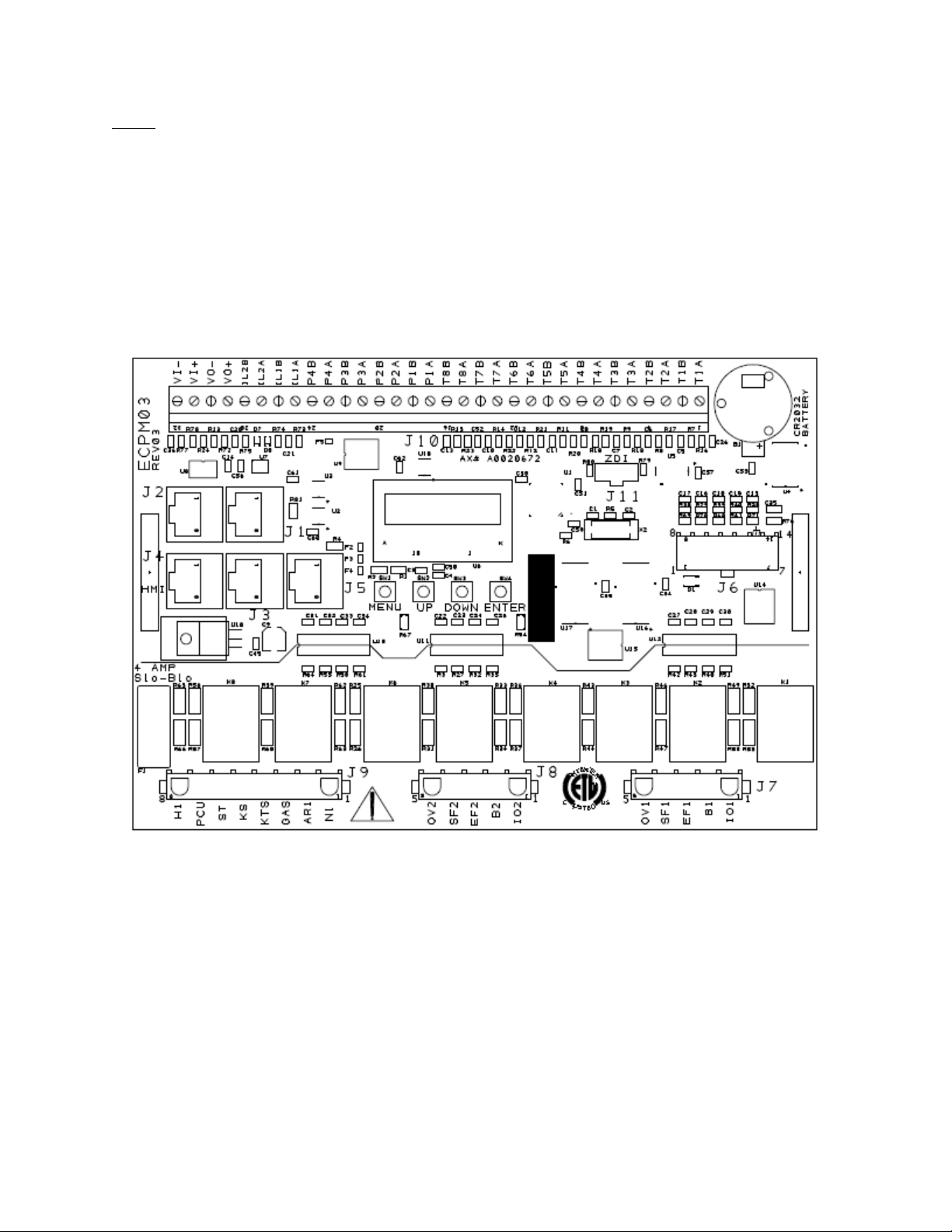
Control board (ECPM03) Technical Information
August 2014 Rev. 7
A0023032
Page 5
5
NOTE: The following is for reference only. All 120 Volt AC field wiring is landed on terminal blocks, not on
the board itself. See Installation section for details. Low voltage class 2 field wiring may be landed at J3,
J4, J5, or J10 connectors only, as indicated by the panel labeling and installation schematic. Provision for
spacing and routing of the field wiring is provided in the panel.
J7, J8, J9 are provided for the control of 120 Volt AC relays, contactors, solenoids and shunt trip
breakers. Under no circumstances shall any lighting or motor loads be directly connected to these
connectors. These connectors are intended to be used for factory wiring only by a UL508A panel shop.
J1, J2, J6, are reserved for low voltage class 2 factory wiring.
Control Board (ECPM03) diagram
A0023032
August 2014 Rev. 7
Page 6

6
INSTALLATION
It is imperative that this unit is installed and operated with the designed airflow and electrical supply in
accordance with the manual and applicable codes. If there are any questions about any items, please call
the service department at 1-866-784-6900 for warranty and technical support issues.
Mechanical
WARNING: DO NOT LIFT CONTROL BY WIRING COMPONENTS
Site Preparation
1. Provide clearance around installation site to safely install equipment into its final position.
Supports must adequately support equipment. Refer to manufacturer’s estimated weights.
2. Consider general service and installation space when locating unit.
Assembly
When the control panel is ordered in a utility cabinet installed on the hood, there is no mechanical
assembly required by the installer. If the control panel is ordered as a wall mounted panel, the enclosure
must be secured to a fixed wall near the exhaust hoods. Be certain to maintain adequate clearance
from excessive heat sources such as appliances to prevent damage of the components.
Utility Cabinet Installation (Typical)
Room Sensor Installation
A room temperature sensor is provided with the panel. It should be installed in a safe location, free of
influence from external heat sources. It should be indicative of the average kitchen temperature away
from the appliances. For packages with 2 separate fan zones, a 2nd room sensor may require installation.
Refer to the Installation Schematic for landing terminal locations.
A0023032
August 2014 Rev. 7
Page 7
7
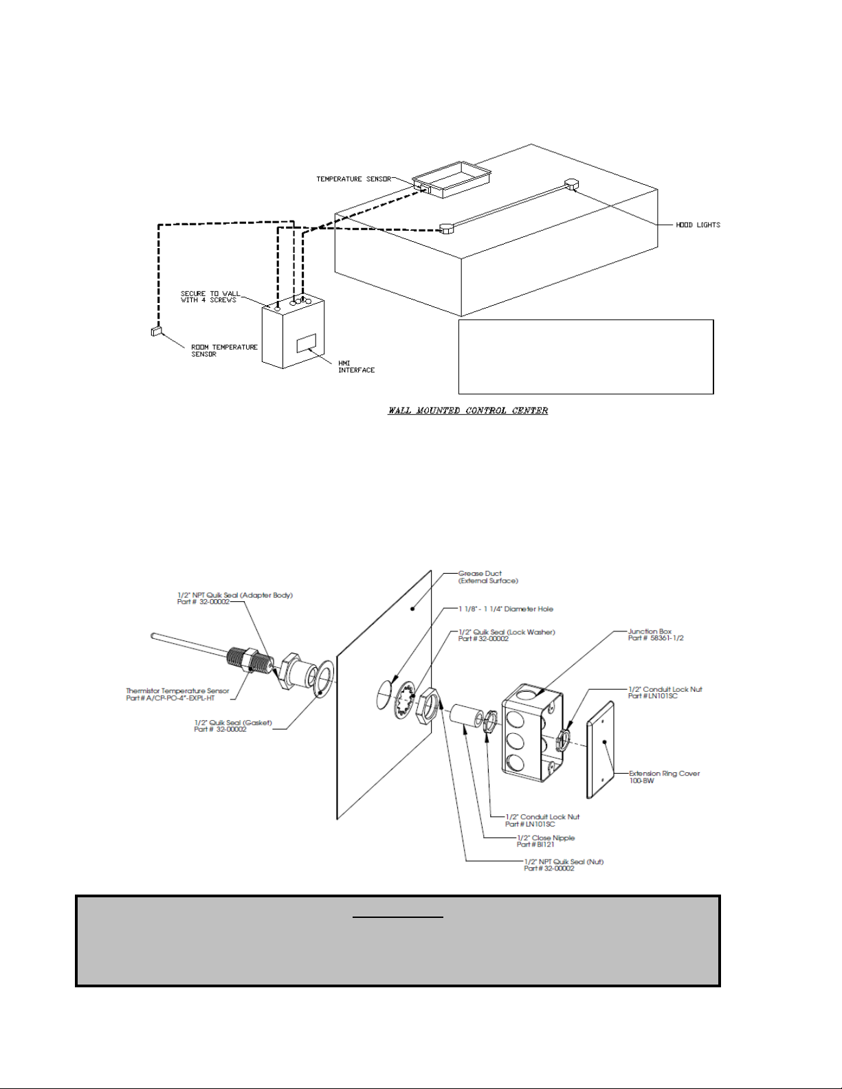
Wall Mount Installation (Optional)
Mount control panel with adequate
clearance from excessive heat
sources such as appliances to prevent
damage of the components.
IMPORTANT!!
When exhaust duct connections are located and cut in the field, duct temperature probes are
shipped loose in the electrical package enclosure. These must be installed in the duct
immediately above the hood for proper system operation.
Duct Sensor Installation
When the control panel is ordered, the system typically consists of one duct sensor per hood exhaust
riser. These sensors are typically shipped factory installed in factory assembled hood risers. If the risers
are field cut, the sensor and other components are shipped loose for field installation as shown below. A
hole must be cut in the grease duct, and the quick seal and sensor must be assembled as shown below.
A 2-wire plenum rated thermistor cable (18 gauge typical), run in conduit, should be used to wire the
sensors back to the controller and landed on connector J10 as indicated on the installation schematic.
A0023032
August 2014 Rev. 7
Page 8
8
Copper Wire Ampacity
Wire Size AWG
Maximum Amps
14
15
12
20
10
30 8 50 6 65 4 85
Electrical
WARNING!!
Disconnect power before
installing or servicing control.
High voltage electrical input is
needed for this equipment. This
work should be performed by a
qualified electrician.
Before connecting power to the control, read and understand
this entire document. As-built wiring diagrams are furnished
with each control by the factory and are attached either to the
door of the unit or provided within a paperwork pouch internal
to the panel.
Electrical wiring and connections should be done in
accordance with local ordinances and the National Electric
Code, ANSI/NFPA70. Be sure the voltage and phase of the
power supply and the wire amperage capacity is in accordance
with the unit nameplate.
1. Always disconnect power before working on or near
this equipment. Lock and tag the disconnect switch or
breaker to prevent accidental power up.
2. Make certain that the power source is compatible with
the requirements of your equipment. The installation
wiring schematic identifies the proper phase and
voltage of the source breakers.
3. Before connecting control to power source, verify
power line wiring is de-energized.
4. Secure all wiring to prevent contact with sharp objects.
5. Do not kink power cable and never allow the cable to come in contact with oil, grease, hot
surfaces or chemicals.
6. Before powering up the system, make sure that the interior of the control is free of loose debris,
metal shavings, or shipping materials. `
7. If any of the original wire supplied with the system must be replaced, it must be replaced with type
THHN wire or equivalent.
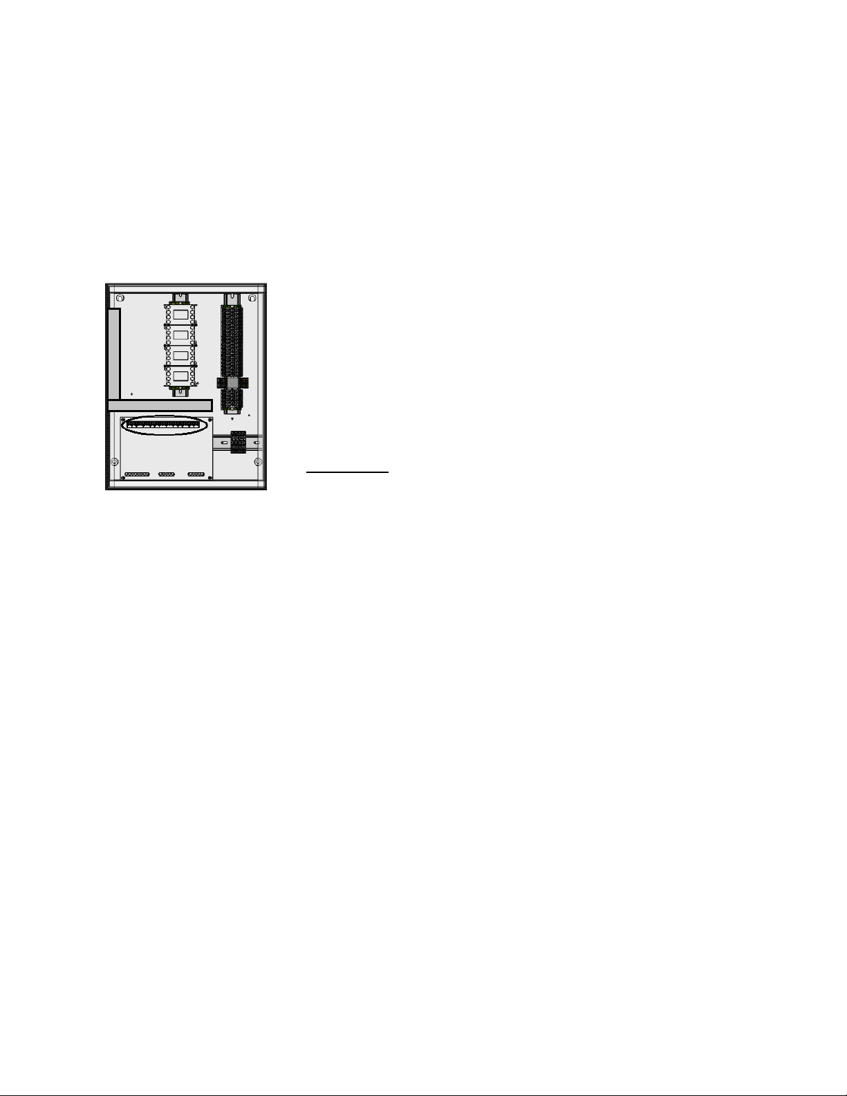
High Voltage Wiring
1. All high voltage wiring shall be terminated on the right side of the
terminal blocks or directly on the starters as designated in the
circled areas on the left hand diagram.
2. There are multiple electrical connections required for this
control. 120VAC should be wired to terminals H1 and N1. Input
power to the motors should be wired to “L” series terminals. Motor
output power should be connected to “T” terminals on the starters.
3. The hood light wiring will also need to be wired to terminals as
indicated on the installation diagram.
4. If an ANSUL fire system is present, the fire system micro-switch will
need to be wired to terminals as indicated on the installation
diagram, typically “C1”, “AR1”. C1 is the common and connects to
terminal 1 on the micro-switch. AR1 is the armed state and
connects to terminal 2 on the micro-switch. If a CORE fire system is
present, this connection is not required.
A0023032
August 2014 Rev. 7
Page 9
9
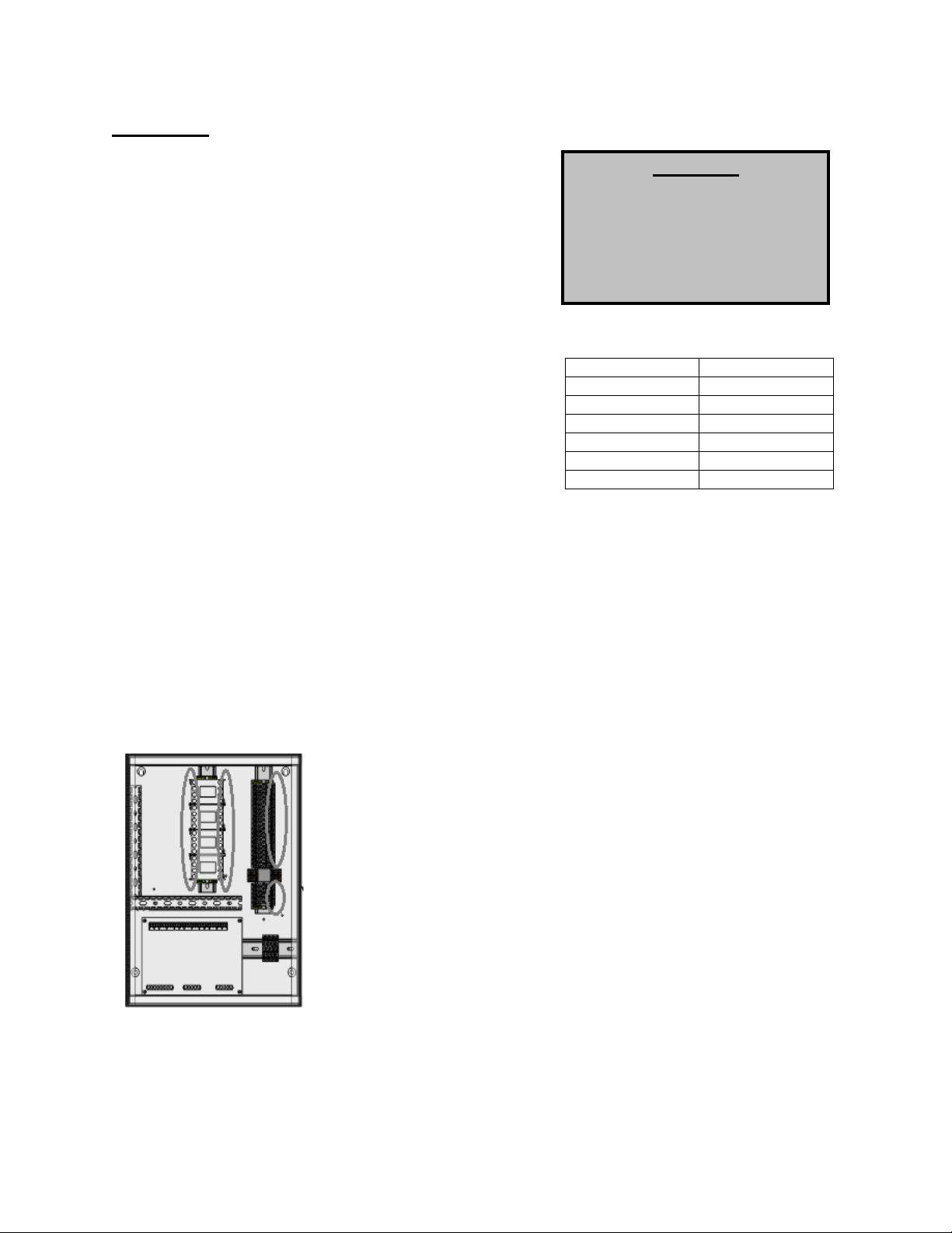
Low Voltage Wiring
Low voltage field wiring consists of Duct and Room Temperature sensors, ECM motors, 0-10VDC output,
24VDC input, or Modbus communication over CAT-5 cables for HMIs and remote equipment.
Additionally, panels can be ordered with Building Management Options. Refer to the Building
Management Owner’s Manual, if equipped, for low voltage building management wiring requirements.
Low voltage wiring must be run through the wireway show below in the grey rectangle area. Wires will be
terminated on the terminals located on the ECPM03 board, circled below.
WARNING: Low voltage wires should never be run together with high voltage wires.
1- Room temperature sensor(s): For all installations utilizing duct
thermostats, at least 1 room temperature sensor must be installed in a
safe location, free of influence from external heat sources. It should be
indicative of the average kitchen temperature away from the appliances.
For packages with 2 separate fan zones, 1 or 2 room sensors can be
used. 2-wire 18 AWG thermistor cable must be used. The room
temperature sensor shall be wired according to the installation wiring
schematic, typically terminals “T1A”,”T1B”.
2- Duct temperature sensors: For all installations excluding a single
hood with factory risers and a hood mounted panel, duct mounted
temperature sensors will need to be wired in the field. 2-wire 18 AWG
plenum rated thermistor cable must be used. The temperature sensor
should be wired to terminal blocks as indicated on the installation wiring
schematic.
3- HMI(s) are connected to the ECPM03 board through CAT-5 cable. The HMI have two RJ-45
connectors connected together for Modbus.
a. If the panel was ordered with only 1 fan switch and/or 1 light switch, the HMI would connect
to port J4 (RJ-45) of the ECPM03 board. The other RJ-45 port of the HMI will typically be
occupied by a RJ-45 end-of-line terminator (Part # EOL120A).
b. If the panel was ordered and configured for 2 fan or 2 light switches, the first HMI would
connect to port J4 (RJ-45) of the ECPM03 board. The second HMI would connect to
ECPM03 board two ways:
o Connect the second HMI to the first HMI through CAT-5 cable. In this case the RJ-45
end-of-line terminator (Part # EOL120A) would only be used on the second HMI.
o Connect the second HMI to port J5 (RJ-45) of the ECPM03 Board. The other RJ-45
port of the HMI will typically be occupied by a RJ-45 end-of-line terminator (Part #
EOL120A).
4- Two end-of-line terminators (Part # EOL120A) are included in each panel. They are typically
plugged in at the factory on J3 and either on port J4 or in the back of the first HMI. If another HMI or
other equipment need to connect to a port occupied by an end-of-line terminator, it shall be removed
and place on the HMI or equipment that became connected at the end of the Modbus network.
NOTE: A third end-of-line terminator would be included with the package if the panel is ordered with 2
fan or 2 light switches. The extra end-of-line terminators will be mounted on the second HMI, if
decided to connect the HMI to J5. Otherwise, if daisy chained both HMIs, the third-end-line terminator
should be mounted on J5.
5- If other pieces of equipment such as PCU Advanced Filter Monitoring (AFM) are connected to this
panel, a cat-5 cable will also be used to run the Modbus communication between these devices. The
cable would be plugged in port J3 of the ECPM03 board. The end-of-line terminators should then be
relocated from J3 to the empty RJ45 port of the PCU AFM module.
A0023032
August 2014 Rev. 7
Page 10

10
OPERATION
Button
Associated
function
Start-Up Procedure
NOTE: FIRE system must be in ARMED state before proceeding.
1. Once all required connections have been completed as indicated on the installation schematic,
startup can begin. Apply power to the panel. The ECPM03 board and the HMI will power up and
beep. If that is not the case, check all power connections. Verify that there is no alarm message
displayed on any HMI screen. If there are alarms present, you can press the MUTE button to
silence the alarm and then work to resolve them.
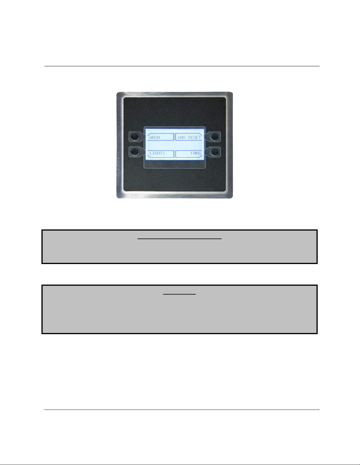
A HMI has 4 buttons; function is displayed adjacent to them on the screen. These functions will
change depending on the status of the panel. If no text is adjacent to the button, it does not have
a function.
Typically LIGHTS and FANS functions are shown on the bottom 2 buttons. The status of those
elements is shown by the shading used inside the box associated with the function. An empty box
around the FAN function means that the FANS are turned OFF. A dark box around the FAN
function means that the FANS are turned ON. The same applies to LIGHTS.
Note: For the rest of the document, the term button will be used to refer to either the actual button
or the function associated with it.
The center two lines of the HMI are reserved for displaying informational or fault messages
When a fault occurs, an audible alarm is triggered and a message is displayed on the HMI(s).
The Audible Alarm can be silenced by pushing the Mute button that appears on the top right
corner.
2. Press the Lights button on the HMI to energize the hood lights. If the lights do not come on,
make sure the light bulbs are installed and/or check the lighting circuit.
3. Press the Fans button on the HMI to energize the fans.
If there are multiple fan zones, pressing the Fans button on the first HMI will only energize the
fans in zone #1. Pressing the Fans button on the second HMI will energize the fans in zone #2.
If the supply fan does not come ON, verify that there is not a Fire Condition Alarm on the screen.
If that is the case, the fire system might be tripped or not properly wired.
4. If cooking appliances are connected to an Electric gas valve controlled by the control panel, the
gas valve can be turned ON by pressing the Gas Reset button on the top right corner of the HMI.
The icon will only show if the Gas Valve Option is turned ON under the ECPM03 menu:
Configuration / Misc. Options / Set Gas Valve, or if a CORE fire protection system is enabled.
A0023032
August 2014 Rev. 7
Page 11

11
5. Turn the Fans off. Turn on the cooking appliance(s) and allow them to reach idle temperature.
The fans should automatically activate as the cooking appliance(s) heats up. The factory set
activation point for duct temperature override of the fan switch is 15 degrees above kitchen room
temperature. Each duct temperature sensor has its own temperature offset setting. These values
should be adjusted based on the cooking appliances and cooking load. Refer to paragraph (e)
under the Configuration section for further details.
6. If the controls include the Self Cleaning or Hood CORE Protection Fire System option, a Wash
button will be displayed on the HMI screen. Push the button to start the wash cycle. Water will be
sprayed in the plenum and duct of the hood and surfactant will be injected at a predetermined
frequency. The wash cycle will stop when the wash timer expires or when the Stop Wash button
is pressed. Make sure Hood filters remain in place during the wash cycle.
7. If the controls include the Proving Interlock Option, as indicated on the installation schematic with
current sensors included inside the package, a calibration step is required at startup. Please refer
to the Fan Proving Interlock section below under Functionality for further details about this
function. To perform the calibration, refer to paragraph (i) under the Configuration section.
August 2014 Rev. 7
A0023032
Page 12

12
Functionality
Fan Control
The control panel controls fans through starters. Each ECPM03 board can control 1 or 2 Fan zones. A fan
zone includes all exhaust fans and supply fans that will come ON and OFF simultaneously. Fan zones
are typically independent from each other, except in certain conditions like fire.
Hood Lights
1. A control panel can have 1 or 2 HMI light switches. Typically each light switch controls one light
circuit with a maximum of 1400W per circuit. If more than 2800 watts of lights are needed,
additional 15 amp circuits can be brought to the panel and be run through a lighting contactor.
Panel specific lighting limitations are indicated on the installation schematic.
2. Hood lights can be controlled manually through the Light button on the HMI screen. They will also
be automatically turned ON or OFF when the fans assigned to that same fan zone turn ON or
OFF. Manual light switch command on the HMI screen always takes priority.
Electric Gas Valve Reset
If the Gas Valve option is turned ON, an additional button is displayed on the HMI screen to allow the
user to reset or re-energize an electric gas valve connected to the panel. The gas valve is de-energized
at initial startup, when the Fire System is triggered or in other conditions as well.
Refer to paragraph (h) under Configuration section to turn this option ON or OFF.
High Temperature Automatic Appliance Shutdown
When any of the duct temperature sensors reads a temperature above the Appliance Shutdown
Temperature threshold settings (Factory Default: 250 Deg °F), any electric gas valve wired to the panel
will shut down and the shunt trip output of the panel will activate. This is intended to prevent potential
fires. The activation threshold set point can be adjusted under Configuration/Fire Options.
Appliances Pilot Check Warning:
Every time an electric gas valve is reset, a warning message will be displayed on the HMI for 1 minute. A
CLEAR button will be displayed on the HMI to clear the warning message and stop the beeps. If after 1
minute, the clear button is not pressed, the message disappears. This message is normal and provided
as a reminder only. There is no need to take any action.
Building Management System (Dry Contact)
1. All controls are equipped with the ability to control the fans via a dry contact BMS interlock.
Terminal IO1 should be energized by closing a dry contact placed between terminals H1 and IO1.
NOTE: the CO Censor option must be disabled for BMS dry contact functionality. If two HMI are
present (two fan groups), terminal IO1 will control the first group, and terminal IO2 will control the
second group.
2. Removing the signal from IO1 will typically cause the fans to turn off. However if the duct
thermostat sensors are hot or if the fans are energized through the fan button on the HMI, then
the fans will continue to run.
NOTE: If the panel is ordered with a digital building management option, such as CASlink, BACnet, or
Lonworks, please refer to the Building Management Owner’s Manual for alternative fan interlock
scheduling.
A0023032
August 2014 Rev. 7
Page 13

13
Minimum Room Temperature
This option is designed to prevent unnecessary automatic fan activation due to excessively cold room
temperatures. This value is adjustable between 50 degrees and 85 degrees. As long as the room
temperature reading is above the Min Room Temp set value, the package will use the actual room
temperature sensor reading to calculate the duct thermostat offset. However, if the room temperature
sensor reading is below the Min Room Temp set value, the package will ignore the actual room temp
reading and use the Min Room Temp set value as a reference instead. This prevents a system from
activating the fans unnecessarily, due to a large gap between room temperature and the hood duct
temperature. This option can also help alleviate fan activation troubles with lower temperature
appliances, which are not satisfying the minimum temperature requirements for fan activation.
Self-Cleaning Function (Optional)
1. During the wash cycle, water will be sprayed in the plenum and duct and surfactant will be
injected at a set frequency. The wash cycle will stop when the wash timer expires or when the
Wash button is pressed again.
2. The wash timer is factory set to 3 minutes and is adjustable through the Configuration Menu. The
surfactant is injected for 1 second at the start of each minute of Wash. This setting is not
adjustable. If equipped with CORE Fire Protection, the wash timer is not configurable through the
ECPM03 control board. Refer to the CORE Owner’s Manual for further information.
3. Hood filters MUST remain in place during the wash cycle.
4. The wash cycle can be initiated in several ways:
a. Manually, when the WASH button is pressed on the HMI.
b. Automatically, if the following conditions are met
Fans will need to go out of modulation mode either with the FANS button being
pressed or by the duct temperature cooling down and hysteresis value and timer
are met.
The fans will need to have effectively run cumulatively for a period of time longer
than the “Wash Min Fan Runtime” value configured under “Misc Options”.
Preparation Time mode and Cool Down mode fan time do not count towards
runtime. The runtime is reset to zero when the wash cycle is run.
The amount of time elapsed since the previous wash cycle is greater than the
“Wash Min Interval time” value configured under “Misc Options”. That elapsed
time is reset to zero when the wash cycle is run.
c. If a Building Management System (BMS) is remotely controlling the fans through the
external input terminal IO1, when the Fans are turned ON and then OFF through the IO1
terminal, granted that the fans are not maintained on by the duct temperature sensors or
the fan button.
d. Through a digital Building Management System. Refer to the Building Management
Owner’s Manual for more information.
5. If the surfactant level is too low, an alarm will be triggered on the HMI. If the wash cycle is
initiated while this alarm is active, water will be sprayed but no surfactant will be injected. Refill
Surfactant as soon as possible for best results. (Refer to Self-Cleaning or CORE Manual for
additional information)
August 2014 Rev. 7
A0023032
Page 14

14
Fan Proving Interlock (Optional) (i.e. Loss of Load Interlock/Airflow Fault
Interlock)
1. This function is only available if there is a supply fan in the system and the panel was ordered
from the factory with current sensors.
2. This function is designed to prevent exhaust fans from running if the supply fans are not running,
which in turn would shut off the cooking equipment. In practical terms, this means that all fans will
shut off along with cooking equipment if any of the exhaust or supply fans are not properly
running. Examples of reasons why a fan would not be properly running are: overload tripped,
broken fan belt, defective motor, disconnect switch off, etc.
3. This function requires calibration, which can be performed through the Configuration/Misc
Options/Proving Calibration setting on the ECPM03 LCD.
4. When fans initially start, the supply fan(s) will be energized first, the motorized damper(s) (if
present) will open. Once open the supply blower(s) will start running which in turn will allow the
exhaust fans to run. If a supply blower doesn’t run within 90 sec, a proving fault will occur.
5. Once the fans are running, the load on all the exhaust and supply fans is constantly monitored. If
the load for an exhaust fan or the load for a supply fan drops below the threshold calculated after
calibration for more than the 15 sec, all exhaust and supply fans will shut down.
6. If an electric gas valve and shunt trip are attached to the system, they will shut down as well.
7. To reset the system after a Proving fault, press the Fault Reset button on the HMI.
CORE Fire Protection System (Optional)
1. If a CORE Protection Fire system is connected to the control panel, alarms from the CORE
system will automatically be displayed on the HMI.
2. Multiple CORE systems can be connected to the same control panel. Refer to the CORE Manual
for setup of CORE Interlock Network addressing to prevent communication conflicts.
PCU Advanced Filter Monitoring (AFM) (Optional)
a If a PCU AFM is connected to the control panel through Modbus, alarms from the PCU will
automatically be displayed on the HMI.
b To connect the AFM system to the HMI, run a cat-5 connection from terminal J3 to the RJ45 port
on the PCU AFM internal to the PCU. This is outlined in the installation schematics.
c Up to 8 PCU AFM can be connected to the same Control panel. . Note that each additional PCU
AFM must be assigned a unique Modbus address. Refer to PCU AFM manual for more
information.
Electric Gas Valve Follow Fans (optional)
This option is only available when an electric gas valve is enabled. If this option is ON, the gas valve is
shut off whenever the fans are off and requires a reset when the fans are turned ON. This is meant to
prevent gas cooking appliances from running when the fans are off and is only required in some
jurisdictions. This option can be enabled under Configuration/Misc Options/Gas Follow Fans. NOTE: Pilot
lights must be relit after each fan cycle when this option is enabled.
Shunt Trip Follow Fans (Optional)
If this option is ON, the shut trip will be energized whenever the fans are off. This is meant to prevent
electric cooking appliances from running when the fans are off and is only required in some jurisdictions.
This option can be enabled under Configuration/Misc Options/Shunt trip Follow Fans.
Dimmable HMI (Optional)
This option allows the backlight on all HMIs to turn off whenever a timer is satisfied. The timer is refreshed
every time the HMI button is pressed. This option is factory set to be disabled and can be enabled under
Configuration/Misc Options/ Set HMI Dimming.
August 2014 Rev. 7
A0023032
Page 15

15
CO Sensor Input (Optional)
If a CO Sensor is wired to the Electric Control package and the CO sensor is triggered, all exhaust fans
will be turned ON and will ramp up to their high speed. All supply fans will be turned OFF, the gas valve
will be shut off, and the shunt trip will be ON. This option is only accessible through terminal IO1.
Terminal IO1 should be energized by closing a dry contact placed between terminals H1 and IO1. CO
sensor should be enabled; otherwise, the IO1 terminal will function as BMS input. Factory Default Setting
is OFF.
PCU CORE ONLY (Optional)
This option can only be enabled if CORE Hood is disabled. If this option is enabled, all the faults
occurring on a connected PCUCORE system will be displayed on the HMI. A cat5 cable will be needed
to connect the PCUCORE to the slave side of the network,typically J3. Factory Default Setting is OFF.
August 2014 Rev. 7
A0023032
Page 16

16
Configuration and Diagnostics
Security
1. To access the Configuration / Factory, the password 1111 must be used.
2. To access the Configuration / Fire Options, the password 1234 must be used.
Setup Options
The ECPM03 board allows the user to configure a broad range of options associated with the functionality
of the system through the setup menus on its LCD as shown above. Below the ECPM03 LCD are 4
buttons for navigation: MENU, UP, DOWN, ENTER.
The MENU button typically takes you up one level in the menu tree while the ENTER button takes you
down one level. UP and DOWN navigate through the same level of the menu tree and also allow the user
to change the value of a parameter.
After changing some parameters in the configuration menus, the user needs to press MENU multiple
times until the screen displays the message “Press any Key to reboot.” As indicated, the processor will
reboot after any key is pressed. This allows the board to correctly process the parameters changed.
NOTE: a reboot of the board will cause the electric gas valve (if equipped) to shut off. Confirm that
gas/pilot lights are re-lit if necessary.
1. Display System Information
Starting from the Main menu, press the DOWN button, press DOWN again. Screen displays
“Info”. Press the ENTER button. Screen displays “Fault History”. Press DOWN to View the
Version number. Press DOWN to view the package Type, which should be “Standard Prewire”.
2. Display Fault History
Starting from the Main menu, press the DOWN button, press DOWN again. Screen displays
“Info”. Press the ENTER button. Screen displays “Fault History”. Press ENTER. Press UP and
DOWN to scroll through the fault history, with 1 being the most recent fault. To clear the fault
history, please ENTER and press ENTER again when prompted “Clear Fault History”. Or press
MENU to go back without clearing.
3. Display temperature readings
Starting from the Main menu, press the DOWN button. Screen displays “Temperatures”. Press
the ENTER button. Press the UP and DOWN buttons to view all temperatures measured by the
room and duct temperature sensors.
A0023032
August 2014 Rev. 7
Page 17

17
4. System Bypass (optional)
This option is designed to bypass the HMI and have the fans running at full speed. Starting from
the Main menu, press UP or DOWN until the screen displays “System Bypass”. Press the ENTER
button. Press the UP or DOWN buttons to activate or deactivate the system bypass. Press enter
to save the selection.
5. Configure Temperature Sensor Assignments
Starting from the Main menu, press the MENU button. Screen displays “Configuration” Press the
ENTER button. Screen displays “Temperature Sensor Assignment”. Press ENTER.
Screen displays “Select Temp Sens to assign:1”
To navigate to another Temperature sensor, press the UP button.
To configure the assignment for Temperature Sensor 1, press ENTER.
a. For Temperature sensor 1, the options are either to follow the room sensor wired to
terminal T1A, T1B (“Room Temp 1”), or to assign a preset room temperature (75°F by
default). Press UP or DOWN to choose the proper option. Press MENU to confirm the
selection. To change the default preset value, press the ENTER button when displaying
the Preset Temperature. Press UP or DOWN to change the preset value. Press MENU
multiple times to get out to main menu.
b. For Temperature sensor 2, the options are: Riser1, Capture Volume 1, Auxiliary Temp,
Hood Coil Input, Hood Coil Output, PSP Discharge, or ACPSP Discharge.
c. If 2 Fan zones are present, the menu for Temperature Sensor 2 will include these
options: Room Temp 2, Riser2, and Capture Volume 2.
d. Riser1 and Capture Volume1 are the only factors that determine how fans connected to
zone 1 are controlled.
If Fan Zone 2 is selected, Riser 2 and Capture Volume 2 would determine how the fans
connected to zone 2 are controlled.
If Room Temp 2 is selected, the sensor reading would be used for fan zone 2 only.
e. The extra options, within each sensor assignment menu, are only used for monitoring
and do not interfere with the control logic.
f. For Temperature sensor 3 and above, the options will be the same as Temperature
Sensor 2 except Room Temp option.
Press MENU multiple times to get out to the main menu and reboot the processor.
6. Configure Temperature Sensor Offset values (Factory Default: 15 Deg °F)
Starting from the Main menu, press the MENU button. Screen displays “Configuration” Press the
ENTER button. Press DOWN. Screen displays “Temperature Sens Offset”. Press ENTER.
Screen displays “Select Temp Sens to assign:2”
Press UP or DOWN to navigate between the different Duct Temperature sensors. Press ENTER
to select one. Then press UP or DOWN to adjust the offset Temperature.
Press MENU multiple times to get out to the main menu and reboot the processor.
7. Enable Electric Gas Valve control (Factory Default: OFF)
Starting from the Main menu, press the MENU button. Screen displays “Configuration” Press the
ENTER button. Press DOWN or UP until the screen displays “Misc Options”. Press ENTER.
Press UP or DOWN until the screen displays “Gas Valve”. Press ENTER. Press UP or DOWN to
turn this option ON or OFF.
Press MENU multiple times to get out to the main menu and reboot the processor.
8. Enable Electric Gas Valve Follow Fans (Factory Default: OFF)
This option is only available when Gas Valve is turned ON. Starting from the Main menu, press
the MENU button. Screen displays “Configuration” Press the ENTER button. Press DOWN or UP
until the screen displays “Misc Options”. Press ENTER. Press UP or DOWN until the screen
displays “Gas Valve Follow Fans”. Press ENTER. Press UP or DOWN to turn this option ON or
OFF.
Press MENU multiple times to get out to the main menu and reboot the processor.
August 2014 Rev. 7
A0023032
Page 18

18
9. Enable Shunt Trip Follow Fans (Factory Default: OFF)
Starting from the Main menu, press the MENU button. Screen displays “Configuration” Press the
ENTER button. Press DOWN or UP until the screen displays “Misc Options”. Press ENTER.
Press UP or DOWN until the screen displays “Shunt Trip Follow Fans”. Press ENTER. Press UP
or DOWN to turn this option ON or OFF.
Press MENU multiple times to get out to the main menu and reboot the processor.
10. Adjust the Temperature Hysteresis (Factory Default: 2°F):
The hysteresis is used to prevent the fans from cycling ON and OFF when the temperature in the
duct is near the activation value. The fans will turn ON when the duct temperature exceeds the
activation value, but they will only turn off when the duct temperature goes below the activation
temperature minus the temperature hysteresis. For example, if the activation Temperature is at
85 °F and Temperature Hysteresis is set to 2 °F, the fans will turn ON at 85 °F and will turn OFF
at 83 °F.
Starting from the Main menu, press the MENU button. Screen displays “Configuration” Press the
ENTER button. Press DOWN or UP until the screen displays “Misc Options”. Press ENTER.
Press UP or DOWN until the screen displays “Set Temp Hyst”. Press ENTER. Press UP or
DOWN to adjust the Hysteresis value. Press ENTER
Press MENU multiple times to get out to the main menu and reboot the processor.
11. Adjust the Hysteresis Timer (Factory Default: 30 min):
The hysteresis is used to prevent the fans from cycling on and off too often due to small
appliances generating just enough heat to turn on the fans but not enough to keep them ON for a
long time. The Hysteresis Timer will maintain the fans on after they have been activated by
temperature for a minimum time set by this timer, even if the temperature in the duct cools back
down.
Starting from the Main menu, press the MENU button. Screen displays “Configuration” Press the
ENTER button. Press DOWN or UP until the screen displays “Misc Options”. Press ENTER.
Press UP or DOWN until the screen displays “Set Hyst Timer”. Press ENTER. Press UP or
DOWN to adjust the Timer value. Press ENTER
Press MENU multiple times to get out to the main menu and reboot the processor.
12. Fan Proving Interlock Settings
If the Fan Proving Interlock option is enabled, two related settings are displayed: Proving
Calibration and Proving Percentage.
a. Calibration is required at startup. To perform calibration, make sure Test and Balance
has been performed on the entire system first. Filters should be in place.
From the previous menu (Misc Option), press DOWN until the screen displays “Set
Proving Calib”. Press ENTER. Press ENTER again to start the Calibration process which
takes about 90 sec. Press MENU once when calibration is complete.
b. Proving Percentage can be adjusted. Value can range between 50% and 100% (factory
default 0.8). The greater the ratio, the tighter the limits will be for fault detection, which
also means the greater likelihood of false positive.
From the previous menu (Misc Option), press DOWN until the screen displays “Set
Proving Percent”. Press ENTER. Press UP or DOWN to adjust the ratio value. Press
ENTER. Press MENU multiple times to get out to the main menu and reboot the
processor.
August 2014 Rev. 7
A0023032
Page 19

19
13. Adjust Wash Time (Min): (Factory Default: 3 min):
This option is available if the control system includes self-cleaning option from the factory. The
wash time value is setup in minutes with a maximum value of 30 minutes.
Starting from the Main menu, press the MENU button. Screen displays “Configuration” Press the
ENTER button. Press DOWN or UP until the screen displays “Misc Options”. Press ENTER.
Press UP or DOWN until the screen displays “Set Wash Time”. Press ENTER. Press UP or
DOWN to adjust the time value. Press ENTER
Press MENU multiple times to get out to the main menu and reboot the processor.
14. Set Wash Min Fan Runtime (Factory Default: 480 min):
This option is available if the control system includes self-cleaning option from the factory. Its
maximum value is 1440 minutes or 24 hours. Refer to the Self-Cleaning Section under
Functionality for more details about this option.
Starting from the Main menu of HMI, press DOWN or UP until the screen displays “Misc Options”.
Press ENTER. Press UP or DOWN until the screen displays “Set Wash Min Fan Runtime”. Press
ENTER. Press UP or DOWN to adjust the time value. Press ENTER. Press MENU multiple times
to get back to the main menu or one more time to reboot the processor.
15. Set Wash Min Interval Time (Factory Default: 720 min):
This option is available if the control system includes self-cleaning option from the factory. Its
maximum value is 1440 minutes or 24 hours. Refer to the Self-Cleaning Section under
Functionality for more details about this option.
Starting from the Main menu of HMI, press DOWN or UP until the screen displays “Misc Options”.
Press ENTER. Press UP or DOWN until the screen displays “Set Wash Min Interval time”. Press
ENTER. Press UP or DOWN to adjust the time value. Press ENTER. Press MENU multiple times
to get back to the main menu or one more time to reboot the processor.
16. Adjust the number of PCU Advanced Filter Monitoring (AFM) Units
If PCU AFM units are connected to the control panel (through Modbus), the number of units has
to be adjusted through this parameter. Refer to the PCU AFM manual for additional information
on how to setup the PCU AFM unit number at the unit control panel.
Starting from the Main menu, press the MENU button. Screen displays “Configuration” Press the
ENTER button. Press DOWN or UP until the screen displays “Misc Options”. Press ENTER.
Press UP or DOWN until the screen displays “Set Number of PCU AFM”. Press ENTER. Press
UP or DOWN to adjust the number of units. Press ENTER. Press MENU multiple times to get out
to the main menu and reboot the processor.
17. Set HMI Dimming (Factory Default: OFF)
Starting from the Main menu, press the MENU button. Screen displays “Configuration” Press the
ENTER button. Press DOWN or UP until the screen displays “Misc Options”. Press ENTER.
Press UP or DOWN until the screen displays “Set HMI Dimming”. Press ENTER. Press UP or
DOWN to turn this option ON or OFF. Press ENTER. Press MENU multiple times to get back to
the main menu or one more time to reboot the processor.
18. Set Dim Delay Time(Factory Default: 60sec)
This option is only accessible when HMI dimming is ENABLED. It allows the user to modify the
time for which the backlight of the HMI remains on before it will turn off. The Dim Delay Time is
factory set to 60 seconds, and is refreshable every time a button on the HMI is pressed. The Dim
Delay Time is adjustable between 10 seconds and 5 minutes.
Starting from the Main menu, press the MENU button. Screen displays “Configuration”. Press the
ENTER button. Press DOWN or UP until the screen displays “Misc Options”. Press ENTER.
Press UP or DOWN until the screen displays “Set DimDelay Time”. Press ENTER. Press UP or
DOWN to adjust the time value. Press ENTER
Press MENU multiple times to get back to the main menu or one more time to reboot the
processor.
August 2014 Rev. 7
A0023032
Page 20

20
19. CO Sensor Input(Factory Default:OFF)
Starting from the Main menu, press the MENU button. Screen displays “Configuration” Press the
ENTER button. Press DOWN or UP until the screen displays “Misc Options”. Press ENTER.
Press UP or DOWN until the screen displays “CO Sensor Input”. Press ENTER. Press UP or
DOWN to turn this option ON or OFF. Press ENTER. Press MENU multiple times to get back to
the main menu or one more time to reboot the processor.
20. Set Min Room Temp(Factory Default: 50 Degrees °F)
Starting from the Main menu, press the MENU button. Screen displays “Configuration” Press the
ENTER button. Press DOWN or UP until the screen displays “Misc Options”. Press ENTER.
Press UP or DOWN until the screen displays “Set Min Room Temp”. Press ENTER. Press UP or
DOWN to adjust the set value. Press ENTER. Press MENU multiple times to get back to the main
menu or one more time to reboot the processor.
21. Set Min Room Temp2(Factory Default: 50 Degrees °F)
This option will only show when the board is configured for two fan zones and the second duct
stat is assigned to Room Temp2.
Starting from the Main menu, press the MENU button. Screen displays “Configuration” Press the
ENTER button. Press DOWN or UP until the screen displays “Misc Options”. Press ENTER.
Press UP or DOWN until the screen displays “Set Min Room Temp2”. Press ENTER. Press UP or
DOWN to adjust the set value. Press ENTER. Press MENU multiple times to get back to the main
menu or one more time to reboot the processor.
22. PCU CORE Only(Factory Default: OFF)
Starting from the Main menu, press the MENU button. Screen displays “Configuration” Press the
ENTER button. Press DOWN or UP until the screen displays “Misc Options”. Press ENTER.
Press UP or DOWN until the screen displays “PCU CORE Only ON/OFF”. Press ENTER. Press
UP or DOWN to turn this option ON or OFF. Press ENTER. Press MENU multiple times to get
back to the main menu or one more time to reboot the processor. NOTE: This will not be present
if HOOD CORE is enabled under the Factory Options menu.
23. Set IO1 Delay Time (Factory Default: 0 min)
This option is intended to be used with some BMSs that require the fans on the first fan zone to
keep running for a specific amount of time right after the BMS signal is OFF. The delay time
value is setup in minutes with a maximum value of 15 minutes.
Starting from the Main menu, press the MENU button. Screen displays “Configuration” Press the
ENTER button. Press DOWN or UP until the screen displays “Misc Options”. Press ENTER.
Press UP or DOWN until the screen displays “Set IO1 Delay Time”. Press ENTER. Press UP or
DOWN to adjust the set value. Press ENTER. Press MENU multiple times to get back to the main
menu or one more time to reboot the processor.
24. Set IO2 Delay Time (Factory Default: 0 min)
This option is intended to be used with some BMSs that require the fans on the second fan zone
to keep running for a specific amount of time right after the BMS signal is OFF. The delay time
value is setup in minutes with a maximum value of 15 minutes.
Starting from the Main menu, press the MENU button. Screen displays “Configuration” Press the
ENTER button. Press DOWN or UP until the screen displays “Misc Options”. Press ENTER.
Press UP or DOWN until the screen displays “Set IO2 Delay Time”. Press ENTER. Press UP or
DOWN to adjust the set value. Press ENTER. Press MENU multiple times to get back to the main
menu or one more time to reboot the processor.
August 2014 Rev. 7
A0023032
Page 21

21
25. Manual to Auto Fans ON/OFF(Factory Default: OFF)
When this option is turned ON and fans are manually turned on, a timer is started. Once the
timer expires, the fans will automatically turn off if the temperature allows them to.
Starting from the Main menu, press the MENU button. Screen displays “Configuration” Press the
ENTER button. Press DOWN or UP until the screen displays “Misc Options”. Press ENTER.
Press UP or DOWN until the screen displays “Manual to Auto Fans ON/OFF”. Press ENTER.
Press UP or DOWN to turn this option ON or OFF. Press ENTER. Press MENU multiple times to
get back to the main menu or one more time to reboot the processor.
26. Manual to Auto Fan Time(Factory Default : 2 hours)
This option allows adjustment of the timer associated with Manual to Auto Fan option. The timer
is adjustable between 1 hour and 18 hours.
Starting from the Main menu, press the MENU button. Screen displays “Configuration” Press the
ENTER button. Press DOWN or UP until the screen displays “Misc Options”. Press ENTER.
Press UP or DOWN until the screen displays “Manual to Auto Fan Time”. Press ENTER. Press
UP or DOWN to adjust the set value. Press ENTER. Press MENU multiple times to get back to
the main menu or one more time to reboot the processor.
27. Configure the Fire Options
This sub-menu is Password protected and changes should not be made after passing an
inspection.
Starting from the Main menu, press the MENU button. Screen displays “Configuration” Press the
ENTER button. Press DOWN or UP until the screen displays “Fire Options”. Press ENTER. When
prompted, enter the password specified under the security section of this manual above. Press
UP or DOWN until one of the options below is displayed. Press ENTER to access that option.
Press UP or DOWN to change the value of that option. Press ENTER to move on to the next
option.
a. Exhaust On in Fire (Factory Default: ON): When this option is turned ON, the exhaust
fans will be turned ON in a fire condition. If the option is turned OFF, the exhaust fans will
stay in whatever state they were before the fire condition.
b. Lights Out in Fire (Factory Default: ON): When this option is turned ON, the hood lights
will be turned OFF in a Fire condition. If the option is turned OFF, the hood lights will stay
in whatever state they were before the fire condition.
c. Supply Off in Fire (Factory Default: OFF): When this option is turned OFF, the Supply
fans will be turned OFF in a Fire condition. If the option is turned ON, the Supply fans will
turn ON in a fire condition.
d. Appliance Shutdown Temp Threshold (Factory Default: 250 Deg °F): When any of the
duct temperature sensors reads a temperature above that threshold, the gas valve shuts
down and shunt trip output is activated.
Once all the changes are complete, press MENU multiple times to get to the main menu and
reboot the processor.
August 2014 Rev. 7
A0023032
Page 22

22
28. Configure Factory Options
This sub-menu is password protected and should only be accessed by the factory since all the
settings under it are directly related to the hardware configuration of the system. Only access this
page if instructed by the manufacturer.
Starting from the Main menu, press the DOWN button until the screen displays “Factory”. Press
ENTER. When prompted, enter the password specified under the security section of this manual
above. Press UP or DOWN until one of the options below is displayed. Press ENTER to access
that option. Press UP or DOWN to change the value of that option. Press ENTER to move on to
the next option.
a. Set Number of Temp Sensors
This includes all Room Temperature Sensors and Duct Temperature sensors connected
to the ECPM03 board. Valid values range from 2 to 32. Set the number of Temp Sensors
to 0 is also a valid, if the system in controlled only by HMI and no temperature sensor is
used.
b. Set Number of Fan Zones:
This defines the number of independent fan zones controlled by the system. There can `
This defines the number of fan switches controlled by the system. There can be 0, 1 or 2
fan switches. A fan switch will be displayed on a HMI accordingly. If 0 is selected, the
fans will be only controlled by the temperature sensors.
c. Set Number of Light switches
This defines the number of hood light switches controlled by the system. There can be 0,
1 or 2 light switches. A light switch will be displayed on the HMI accordingly.
d. Set Proving Enable
This option enables or disables the Fan Proving Interlock. Refer to the Fan Proving
Interlock paragraph under Functionality for further details. If this option is enabled,
Proving calibration is required. Refer to paragraph i under Setup Options.
e. Set Hood CORE
This option determines if the system is connected to a CORE Fire Protection system.
f. Set Wash
This option determines if the system includes a self-cleaning option. This option will not
be available if CORE is enabled.
g. Set KTS
This option determines if a Kill switch or Tamper switch are connected to the system. If
this option enabled, the input KTS shall be maintained energized for normal cooking
operations. If KTS is deenergized, an electric gas valve connected to the system would
drop and the shunt trip output will be energized.
Once all the changes are complete, press MENU multiple times to get out to the main menu and
reboot the processor.
A0023032
August 2014 Rev. 7
Page 23

23
Component Description
Temperature Sensor
The temperature sensor is a 10K Ohm Thermistor. The
sensor gives constant feedback to the controller. One
sensor is installed in every riser.
Room Temperature Sensor
The Room temperature sensor is a 10K Ohm Thermistor. The sensor provides constant
room temperature to the controller. It should be installed on a wall somewhere in the
space but not directly under the hood or close to an appliance so that the reading is not
affected by heat.
Typically a system will have one room temperature sensor. However systems
configured with 2 fan zones have the option to be ordered with 2 room temperature
sensors, one for each zone. They should be mounted in the space accordingly.
HMI
The HMI is designed to withhold grease and water when installed on
the face of the hood or utility cabinet.
The HMI is connected to the ECPM03 through a CAT-5 cable. If the
HMI is installed on the face of the hood, a high temperature CAT-5
Cable is used.
The HMI can be mounted to a standard 2-gang junction box.
Current Sensor
One or several current sensors are included in the panel when the
Proving Option has been ordered. A current sensor has a solid core and
provides a 4-20 mA analog output that is proportional to the current
measured. It has an adjustable range of 0-10 amp, 0-20 amp or 0-50
amp based on the position of the jumper on the top of it: L, M or H
respectively. The jumper is typically adjusted at the factory. The range
selected should be the smallest range possible that includes the FLA of
the motor being monitored.
August 2014 Rev. 7
A0023032
Page 24

24
ECPM03 board
The ECPM03 is the main brain of the system. It receives all the digital and analog inputs, delivers the
digital outputs, and sends out messages to other devices.
Connector Descriptions
J1, J2: Modbus slave network connectors feed through
RJ45s, which conform to the Modbus pin out for RS485 2
wire differential Modbus RTU standard. See
http://www.modbus.org. Modbus communication is not
configured for third party integration without additional
components.
J3, J4, J5: Modbus master network connectors, feed through RJ45s, which conform to the
Modbus pin out for RS485 2 wire differential Modbus RTU standard. J4 or J5 are the only RJ45
port on the ECPM03 which serves as a power source for HMI(s).
J6 Factory low voltage connections
o Pin 1 positive side of the 24 Volt DC input to the board
o Pin 2 – 7 Open collector outputs, 100ma max each, suitable for driving 24VDC relays or
indicator lamps.
o Pin 8 – 12 4-20ma current inputs. 150 Ohm impedance to 24 VDC ground pin 14.
o Pin 13 Chassis ground connection, this pin connects to the 24VDC ground through a
paralleled 1000pf 2000V cap and a 100k Ohm 1/4W resistor.
o Pin 14 negative side of the 24 volt DC power input (ground or common side of the low
voltage circuitry)
J7: 120 VAC control connector for factory wiring
o Pin 1 IO1, BMS input, can detect the presence of 120VAC, this forces the fans on.
o Pin 2 B1, input, this pin can detect the presence of 120VAC
o Pin 3 EF1, output and input, this pin can source 120VAC and detect the presence of
120VAC
o Pin 4, SF1, output, this pin can source 120VAC
o Pin 5, OV1, input, this pin can detect the presence of 120VAC
J8: 120 VAC control connector for factory wiring
o Pin 1 IO2, output and input, this pin can source 120VAC and detect the presence of
120VAC
o Pin 2 B2, input, this pin can detect the presence of 120VAC
o Pin 3 EF2, output and input, this pin can source 120VAC and detect the presence of
120VAC
o Pin 4, SF2, output, this pin can source 120VAC
o Pin 5, OV2, input, this pin can detect the presence of 120VAC
J9: 120 VAC control connector for factory wiring
o Pin 1 N1, Neutral, this is the neutral or return path for the detection of 120VAC by the
input pins. It would be connected to the Neutral side of the 120 VAC supply
o Pin 2 AR1, input, this pin can detect the presence of 120VAC
o Pin 3 GAS, output, this pin can source 120VAC
o Pin 4 KTS, input, this pin can detect the presence of 120VAC
o Pin 5 KS, output, this pin can source 120VAC
o Pin 6 ST, output, this pin can source 120VAC
o Pin 7 PCU, input, this pin can detect the presence of 120VAC
o Pin 8 H1, this is the 120 Volt AC 50/60Hz input to the board, it feeds through an on board
4 Amp Slo-Blo fuse and is used to source 120 VAC to all the pins described as 120 VAC
outputs. The total current draw of all the 120VAC outputs must not exceed 4Amps.
August 2014 Rev. 7
A0023032
Page 25

25
J10 Low voltage field connections
Problem
Potential Cause
Corrective Action
Smoke Rollout of Hood – Fans
don’t start-up when appliances
are ON
Dirty temperature sensor
Clean grease and dirt from
sensor
Poor Heat detection
Decrease duct Temperature
offset values
Improper hood installation
Check for proper hood overhang,
cross drafts or improper hood
design
Fans Spin Wrong Direction
3 phase Motor output wired
backward
Swap 2 of the 3 phase wires on
the output of the starter feeding
the motor
Light icon On but No Lights
Come On
Light bulbs are blown
Replace hood light bulbs
Loose wiring connection
Check light terminal block wiring
connections
Fan icon On but Fan doesn’t
comes On
Broken fan belt
Replace fan belt
Loose wiring connection
Check wiring connections on
starters
o Pin 1,2 – 15,16 thermistor temperature probe inputs. 10k type B thermistors are
connected to these inputs.
o Pin 17, 19, 21, 23, 25, 27, sources 24VDC which is current limited through an on board
200ma PTC Poly-Fuse. This is the high side of the pulse with modulated outputs, and low
voltage inputs listed below.
o Pin 18, 20, 22, 24 Open collector PWM outputs, 100ma max each. Suitable for driving
the opto-isolated PWM speed control inputs of ECM motors.
o Pin 26, 28 low voltage inputs, suitable for detecting dry contact closures with pins 25, 27
above.
o Pin29 0-10 Volt output, 5ma max, suitable for driving instrumentation inputs.
o Pin 30, negative, common or ground side of the above 0-10 Volt output
o Pin 31 0-10 Volt input, 10k Ohm impedance to ground or common.
o Pin 32, negative, common or ground side of the above 0-10 Volt output
J11: factory programming only, Zilog ZDI microcontroller debug/programming interface
o Pin 1 3.3VDC
o Pin 2 /reset
o Pin 3,5 GND
o Pin 4 DBG input
o Pin 6 NC
Troubleshooting
The following table lists causes and corrective actions for possible problems with this control. Review this
list prior to consulting manufacturer.
Troubleshooting Chart
August 2014 Rev. 7
A0023032
Page 26

26
The following table lists Fault messages displayed on the HMI and corrective actions. Review this list prior
Fault Message on HMI
Potential Cause
Corrective Action
“Fire”
FIRE or fire circuit not wired
properly.
If no fire, verify connection between
terminal blocks C1 and AR1.
“Equipment Disable
High Temp”
Duct temperature exceeded the
High Temp Equipment shutdown
Threshold and shut down the gas
valve and energizes the shunt trip.
Verify why Temp in duct is high.
Verify the Threshold value under
Configuration is set sufficiently high
(250 deg default).
“Light Fault Zone x
Bx De-energized”
(x=1 or 2)
Light output is energized but no
power is detected on terminal Bx.
Verify that the light relay is not
damaged and that the light circuit
breaker is not tripped.
“Light Fault Zone x
Bx energized” (x=1 or 2)
Light output is de-energized but
power is detected on terminal Bx.
Verify that the light relay contact is
not welded in the close position.
“Overload Trip
Zone x” (x=1 or 2)
One of the overload relays for fans
associated with zone x is tripped.
Reset overload relay. Monitor fan to
see why overload tripped.
“Surfactant Low”
Surfactant level is low.
Refill Surfactant into the tank. Refer
to Self-Cleaning or CORE manual.
“PCU Fault”
PCU filters are clogged or missing.
Verify PCU filters and replace if
needed.
“Proving Fault”
Fan Proving Interlock enabled.
Exhaust fan not meeting its
minimum calibrated load.
Verify fans are running properly.
Verify Fan Proving calibration. Refer
to Fan Proving Interlock section.
“Fuse F1 Blown”
Fuse F1 is blown or missing
Replace fuse and verify there is no
short-circuit and load is below 4
amps.
“Temp Sensor x
Not Connected”
Temperature sensor x is not wired
to the ECPM03 board.
Verify proper wiring to terminals TxA
and TxB on the board and wiring to
the sensor.
“Modbus Communication
Fault”
One or several components on the
Modbus network are not
responding.
Verify HMIs are all plugged in. Verify
CORE or PCU AFM are plugged in if
configured as such.
“CORE x Fault”
Fault description
Specific fault is present on the
CORE fire system
Refer to the CORE manual for
specific fault description.
“PCU x Fault”
Fault description
Specific fault is present on the PCU
AFM x connected to the system.
Refer to the PCU AFM manual for
specific fault description.
“Temp Sensor x
Bad Sensor”
Bad Temp Sensor due to
overheating or internal failure
Replace the Temperature Sensor
“Communications fault
Check Configuration”
ECPM03 board and HMI not
communicating due to:
Software incompatible
Switchplate # doesn’t
match number of zones
Re-flash the HMI
Change switchplate #
Replace cat5 cable
Replace EOL
to consulting manufacturer.
August 2014 Rev. 7
A0023032
Page 27

27
MAINTENANCE
To guarantee trouble free operation of this control, the manufacturer suggests following these guidelines.
Most problems associated with unit failures are directly related to poor service and maintenance.
Please record any maintenance or service performed on this equipment in the documentation section
located at the end of this manual.
WARNING: DO NOT ATTEMPT MAINTENANCE ON THIS CONTROL UNTIL THE ELECTRICAL
SUPPLY HAS BEEN COMPLETELY DISCONNECTED
General Maintenance
1. Control enclosure should be kept clean and free from any grease or dirt build-up.
2. All fasteners should be checked for tightness each time maintenance checks are preformed prior
to restarting unit.
3. Control enclosure door panel should be securely closed after maintenance to prevent tampering
or electrical shock.
4. Real Time Clock (RTC) battery should be replaced every 10 Years.
Every Month
1. Temperature sensor(s) in exhaust hood riser(s) need to be cleaned by wiping any grease or
dust build-up from probe with a clean cloth. A clean sensor ensures that the temperature switch
will quickly respond to changes in exhaust air temperature.
2. Check all fasteners, sensors, and electrical connections for proper tightness and continuity.
Self-Cleaning
Please refer to the Self-Cleaning or CORE Manual for Installation, Operation, and Maintenance of the
Self-Cleaning system.
August 2014 Rev. 7
A0023032
Page 28

28
Start-Up and Maintenance Documentation
Job Name
Service Company
Address
Address
City
City
State
State
Zip
Zip Phone Number
Phone Number
Fax Number
Fax Number
Contact
Contact
Purchase Date
Start-Up Date
Date
Service Performed
START-UP AND MEASUREMENTS SHOULD BE PERFORMED AFTER THE SYSTEM HAS BEEN
AIR BALANCED (Warranty will be void without completion of this form)
Job Information
Maintenance Record
Factory Service Department
Phone: 1-866-784-6900
Fax: 1-919-554-9374
A0023032
August 2014 Rev. 7
 Loading...