

Page 1
EVAPORATOR COIL (DX)
INSTALLATION
OPERATION
AND
MAINTENANCE
Commercial Products
PO Box 1457 / 1000 Heatcraft Drive, Grenada, MS 38902-1457
Tel: 800-225-4328 / 662-229-4000 Fax: 662-229-4212
Email: coils@heatcraft.com
Web Site: www.heatcraft.com
Page 2

EVAPORATOR IOM
Guidelines for the installation, operation and maintenance of Heatcraft’s direct expansion (DX)
cooling coils have been provided to help insure proper performance of the coils and their longevity .
These are general guidelines that may have to be tailored to meet the specific requirements of any
one job. As always, a qualified party or individual should perform the installation and maintenance
of any coil. Protective equipment such as safety glasses, steel toe boots and gloves are recommended
during the installation and routine maintenance of the coil.
Receiving Instructions
1. All Heatcraft coils are factory tested, inspected and carefully packaged.
2. Damage to the coils can occur after they have left the factory . Therefore, the coils should
be inspected for shipping damage upon receipt. The freight bill should also be checked
against items received for complete delivery .
3. Damaged and/or missing items should be noted on the carrier’s freight bill and signed by
the driver.
4. For additional assistance, contact your local Heatcraft representative.
Nomenclature
Tube O.D. Finned Length (inches)
4=1/2”
5=5/8” Fin Height (inches)
Coil Type Fin Design
E = Evaporator A - flat (Al, Cu)
Circuiting C - sine wave (Al, Cu)
N = Normal F - flat (SS, CS, Al, Cu)
F = Face Control G - corrugated (SS, CS, Al, Cu)
R = Row Control H - sine wave (SS, CS, Al, Cu)
J = Interlaced
K = Interlaced Face Control Rows Deep
Mounting
1. Position the coil such that the suction header is at the entering air-side of the coil and the
distributor tubes are at the leaving air-side of the coil. This orientation provides counterflow heat exchange which is required for proper coil performance.
2. The suction connection is located at the bottom of the coil when properly installed.
5 E N 14 06 C 24.00 x 144.00
B - corrugated (Al, Cu)
Fins Per Inch
3. See Figure 1 - Evaporator Coils.
1
Page 3
EVAPORATOR IOM
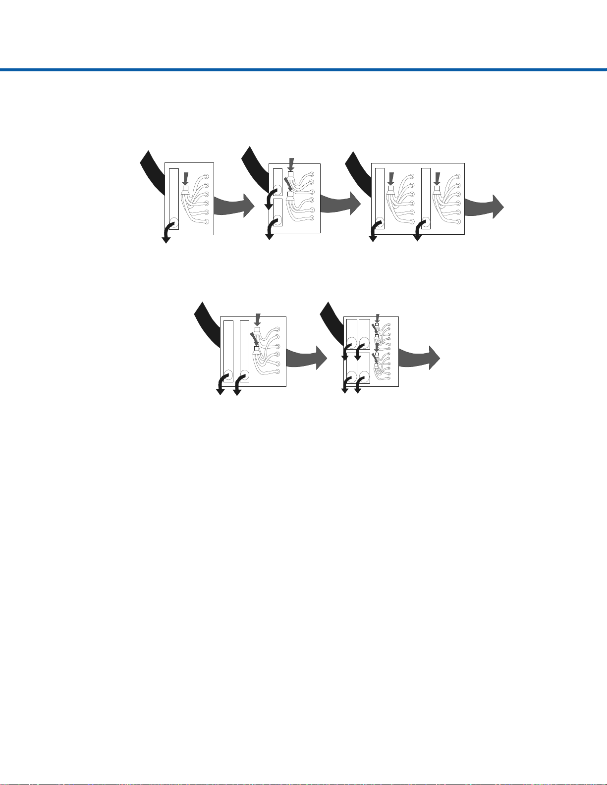
EN
NORMAL
Rows
2,3,4,5
6,8,10,12
FACE CONTROL
6,8,10,12
EJ
INTERLACED
Rows
3,4,6,8,10,12
2 Distributors
EF
Rows
2,3,4,5
ER
ROW CONTROL
6 Row
EK
INTERLACED
Face Control
Rows 4,6,8,10,12
4 Distributors
Figure 1 - Evaporator Coils
Coil Types
1. Heatcraft’s model EN evaporator is used for applications where capacity control is not
required. Single or multiple distributors are available depending on the number of circuits required. Model EN evaporators utilize dual suction connections when multiple
distributors are used.
2. Face control (model EF) is another evaporator coil option offered by Heatcraft. Face
control is the simplest form of capacity control. Type EF coils are normally furnished
with two distributors and two suction connections offering 50% capacity reduction capabilities.
3. Heatcraft offers a row control (ER) option for six row evaporators. These coils are split
two rows and four rows which offer approximately a 50% capacity reduction.
4. Heatcraft’s EJ coils come with interlaced circuiting. This form of capacity control utilizes two distributors with each feeding every other tube in the first row of the coil. Each
distributor has a separate suction connection.
5. For applications that require face control and interlaced circuits, Heatcraft offers evaporator model EK. Interlaced face control utilizes four distributors and four suction connections.
6. See Figure 1 - Evaporator Coils.
2
Page 4

EVAPORATOR IOM
Installation
1. Carefully remove the coil from the shipping package to avoid damage to the finned area.
Damaged fins can be straightened using an appropriate fin comb.
2. Heatcraft recommends cleaning the coil with a commercially available coil cleaner prior
to installation. Refer to Maintenance on Page 6 for cleaning recommendations.
3. Proper clearance should be maintained between the coil and other structures such as the
fan, filter racks, transition areas, etc.
4. Inspect the refrigerant distributor and verify that the nozzle is in place. The nozzle is
generally held in place by a retaining ring or it is an integral part of the distributor itself
(see Figure 2 - Distributor). If a hot gas bypass kit was ordered with the coil, the nozzle
will be located in it rather than the distributor (see Figure 3 - Hot Gas Bypass Kit).
5. All field brazing and welding should be performed using high quality materials and an
inert gas purge (such as nitrogen) to reduce oxidation of the internal surface of the coil.
6. If a hot gas bypass kit was ordered with the coil install it now. Complete installation
instructions are in the box that contains the hot gas bypass kit. Align the side port with
the hot gas line prior to brazing into place.
7. Connect the suction line and suction connection.
8. Install the expansion valve. Follow the expansion valve manufacturer’s recommendations for installation to avoid damaging the valve. If the valve is externally equalized, use
a tubing cutter to cut off the plugged end of the factory installed equalizer line. Next, use
a de-burring tool to remove any loose metal from the equalizer line and attach it to the
expansion valve. If the valve is internally equalized, the factory installed equalizer line
can be left as is or it can be cut back and sealed.
9. The expansion valve’s remote sensing bulb should be securely strapped to the horizontal
run of the suction line at the 3 or 9 o’clock position and insulated.
10. Connect the liquid line to the expansion valve.
Pressurize the coil, expansion valve assembly and suction connection to 100 psig with
dry nitrogen or other suitable gas. The coil should be left pressurized for a minimum of
10 minutes.
11. If the coil holds pressure, the hook-up can be considered leak free. If the pressure drops
by 5 psi or less, repressurize the coil and wait another 10 minutes. If the pressure drops
again, there are more than likely one or more small leaks, which should be located and
repaired. Pressure losses greater than 5 psi would indicate a larger leak, which should be
isolated and repaired. Be sure to check valves and fittings as potential sites for leakage
or bleed. If the coil is found to be leaking, contact your local Heatcraft representative.
Unauthorized repair of the coil may void the coil’s warranty (see Heatcraft’s warranty
policy on back cover).
3
Page 5

EVAPORATOR IOM
12. Use a vacuum pump to evacuate the coil and any interconnecting piping that has been
open to atmosphere. Measure the vacuum in the piping using a micron gauge located as
far from the pump as possible (the vacuum at the pump will be greater than the rest of the
system). Evacuate the coil to 500 microns or less then close the valve between the pump
and the system. If the vacuum holds to 500 microns or less for one minute, the system is
ready to be charged or refrigerant pumped down in another portion of the system can be
opened to the coil. A steady rise in microns would indicate that moisture is still present
and that the coil should be further vacuumed until the moisture has been removed.
13. Failure to obtain a high vacuum is indicative of a great deal of moisture or a small leak.
Break the vacuum with a charge of dry nitrogen or other suitable gas and recheck for
leaks (soapy water works well). If no leaks are found, continue vacuuming the coil until
the desired vacuum is reached.
14. All field piping must be self-supporting.
15. Refer to Figures 4 - Hot Gas Bypass Kit Installed and Figure 5 - General Diagram, for
general piping.
Figure 2 - Distributor
Figure3 - Hot Gas Bypass Kit
4
Page 6

EVAPORATOR IOM
y
g
Suction Header
Liquid Line
Distributor
Equalizer Line
Nozzle
Expansion Valve
Hot Gas B
-Pass
Hot Gas Side Port
Suction Line
Remote Sensing Bulb
Straps
Figure 4 - Hot Gas Bypass Kit Installed
Coil
Suction Connection
Liquid Line
Exp an sion Valve
Suction Line
Remote Sensin
Figure 5 - General Diagram
5
Distributor
Equalizer Line
Nozzle
Bulb
Suction Header
Straps
Coil
Suction Connection
Page 7

Operation
1. Proper air distribution is vital to coil performance. Air flow anywhere on the coil face
should not vary by more than 20%.
2. Air velocities should be maintained between 200 and 550 feet per minute.
3. The drain pan should be designed and installed such that there is no standing water .
Maintenance
1. Filters should be inspected on a regular basis and changed as needed. Maintaining clean
filters is a cost-effective way to help maintain maximum coil performance and service
life.
2. Periodic inspection of the coil for signs of corrosion and for leaks is recommended.
Small leaks can be detected using a Halide torch. Repair and replacement of the coil and
the connecting piping, valves, etc., should be performed as needed by a qualified
individual(s).
EVAPORATOR IOM
3. Should the coil surface need cleaning, caution should be exercised in selecting the cleaning solution as well as the cleaning equipment. Improper selection can result in damage
to the coil and/or health hazards. Clean the coil from the leaving air-side so that foreign
material will be washed out of the coil rather than pushed further in. Be sure to carefully
read and follow the manufacturer’s recommendations before using any cleaning fluid.
4. The use of filter-dryers in the system piping is recommended along with a sight glass that
has a moisture indicator. Replace the filter dryer(s) as needed.
Note: Refrigerant conversions are beyond the scope of this manual and should only be performed by
qualified parties.
6
Page 8

Commercial Products
WARRANTY
The Heat Transfer Division of Heatcraft Inc., hereinafter referred to as the “Company”, warrants that it will provide
free suitable repair or replacement of coils in the event any coil of its manufacture used in the United States proves
defective in material or workmanship within twelve (12) months from the date shipped by the Company.
THIS WARRANTY CONSTITUTES THE BUYER’S SOLE REMEDY. IT IS GIVEN IN LIEU OF ALL OTHER
WARRANTIES. THERE IS NO IMPLIED WARRANTY OF MERCHANT ABILITY OR FITNESS FOR A
P AR TICULAR PURPOSE. IN NO EVENT AND UNDER NO CIRCUMSTANCE SHALL THE COMPANY BE
LIABLE FOR INCIDENTAL OR CONSEQUENTIAL DAMAGES, WHETHER THE THEORY BE BREACH
OF THIS OR ANY OTHER WARRANTY, NEGLIGENCE, OR STRICT TORT.
This warranty extends only to the original purchaser. Of course, abuse, misuse, or alteration of the product
in any manner voids the Company’s warranty obligation.
This warranty does not obligate the Company to pay any labor or service costs for removing or replacing
parts, or any shipping charges.
No person (including any agent or salesman) has authority to expand the Company’s obligation beyond the
terms of this express warranty , or to state that the performance of the coil is other than that published by the
Heat Transfer Division of Heatcraft Inc.
PO Box 1457 / 1000 Heatcraft Drive, Grenada, MS 38902-1457
Tel: 800-225-4328 / 662-229-4000 Fax: 662-229-4212
Email: coils@heatcraft.com
Web Site: www.heatcraft.com
Printed in U.S.A.
December 1999
 Loading...