

Page 1

RECEIVING AND INSPECTION
Upon receiving unit, check for any interior and exterior damage, and if found, report it
immediately to the carrier. Also check that all accessory items are accounted for and are
damage free.
WARNING!!
Installation of this control panel should only be performed by a qualified professional who has
read and understands these instructions and is familiar with proper safety precautions.
Improper installation poses serious risk of injury due to electric shock and other potential
hazards. Read this manual thoroughly before installing or servicing this equipment. ALWAYS
disconnect power prior to working on module.
Demand Control Ventilation System
Installation, Operation, and Maintenance Manual
Save these instructions. This document is the property of the owner of this equipment and is
required for future maintenance. Leave this document with the owner when installation or
service is complete.
A0023662
May 2014 Rev. 5
Page 2

2
TABLE OF CONTENTS
Demand Control Ventilation System ............................................................................................................. 1
Installation, Operation, and Maintenance Manual ........................................................................................ 1
WARRANTY .................................................................................................................................................. 3
SAFETY INFORMATION .............................................................................................................................. 4
General ................................................................................................................................................. 4
Installation............................................................................................................................................. 4
Control board (ECPM03) Technical Information .................................................................................. 4
INSTALLATION ............................................................................................................................................. 6
Mechanical ................................................................................................................................................ 6
Site Preparation .................................................................................................................................... 6
Assembly .............................................................................................................................................. 6
Room Sensor Installation ..................................................................................................................... 6
Utility Cabinet Installation (Typical) ...................................................................................................... 6
Wall Mount Installation (Optional) ........................................................................................................ 7
Duct Sensor Installation ........................................................................................................................ 7
Electrical ................................................................................................................................................... 7
Copper Wire Ampacity .......................................................................................................................... 8
High Voltage Wiring .............................................................................................................................. 8
Low Voltage Wiring ............................................................................................................................... 9
Variable Frequency Drive (VFD) Installation Instructions .................................................................. 10
OPERATION ............................................................................................................................................... 12
Start-Up Procedure ................................................................................................................................. 12
Sequence of Operation ........................................................................................................................... 13
Functionality ............................................................................................................................................ 15
Fan Control ......................................................................................................................................... 15
Preparation Time Mode ...................................................................................................................... 15
Hood Lights ........................................................................................................................................ 15
Electric Gas Valve Reset .................................................................................................................... 15
High Temperature Automatic Appliance Shutdown ........................................................................... 15
Make-Up Air Interlock ......................................................................................................................... 15
Appliances Pilot Check Warning: ....................................................................................................... 16
Building Management System (Dry Contact) ..................................................................................... 16
Minimum Room Temperature ............................................................................................................. 16
Self-Cleaning (Optional) ..................................................................................................................... 16
Fan Proving Interlock (Optional) (i.e. Loss of Load Interlock/Airflow Fault Interlock) ........................ 17
CORE Protection Fire System (Optional) ........................................................................................... 17
PCU Advanced Filter Monitoring (AFM) (Optional) ............................................................................ 17
Electric Gas Valve Follow Fans (optional) .......................................................................................... 17
Shunt Trip Follow Fans (Optional) ...................................................................................................... 18
Dimmable HMI (Optional) ................................................................................................................... 18
CO Censor Input (Optional) ................................................................................................................ 18
PCU CORE ONLY (Optional) ............................................................................................................. 18
Energy Saving Graph (optional) ......................................................................................................... 18
Configuration and Diagnostics ................................................................................................................ 19
Security ............................................................................................................................................... 19
Setup Options ..................................................................................................................................... 19
Component Description ............................................................................................................................... 28
Variable Frequency Drive ................................................................................................................... 28
ECPM03 board ................................................................................................................................... 28
Temperature Sensor ........................................................................................................................... 30
Room Temperature Sensor ................................................................................................................ 30
HMI ..................................................................................................................................................... 30
Troubleshooting .......................................................................................................................................... 31
MAINTENANCE .......................................................................................................................................... 33
A0023662
May 2014 Rev.5
Page 3

3
WARRANTY
This equipment is warranted to be free from defects in materials and workmanship, under normal use and
service, for a period of 12 months from date of shipment. This warranty shall not apply if:
1. The equipment is not installed by a qualified installer per the MANUFACTURER’S installation
instructions shipped with the product,
2. The equipment is not installed in accordance with federal, state and local codes and regulations,
3. The equipment is misused or neglected,
4. The equipment is not operated within its published capacity,
5. The invoice is not paid within the terms of the sales agreement.
The MANUFACTURER shall not be liable for incidental and consequential losses and damages
potentially attributable to malfunctioning equipment. Should any part of the equipment prove to be
defective in material or workmanship within the 12-month warranty period, upon examination by the
MANUFACTURER, such part will be repaired or replaced by MANUFACTURER at no charge. The
BUYER shall pay all labor costs incurred in connection with such repair or replacement. Equipment shall
not be returned without MANUFACTURER’S prior authorization and all returned equipment shall be
shipped by the BUYER, freight prepaid to a destination determined by the MANUFACTURER.
A0023662
May 2014 Rev.5
Page 4

4
Ratings
24VDC, 10-20Watts
Other Ratings
On-board relay contacts are 120VAC with 4Amps Max
Flammability
FR4 board with 94V0 flammability rating
IP rating
IPX0
Fuse on board
Slo-Blo 4 Amp fuse, 5x20mm
Humidity
< 95% non-condensing
Temperature range
-10 to +55°C or +15 to +130 °F
Battery
Model 2032 - Lithium Coin Cell, 3VDC, 0.043mA
Dimensions
203mm L x 140mm W x 46mm H
Weight
0.6 lbs.
SAFETY INFORMATION
General
This control panel utilizes a mixture of traditional controls along with a “smart” digital circuit board
controller, referred to as the ECPM03 control board. It is intended to be installed within a UL508A
electrical control package. The board is powered by 24 Volts DC, which is provided by an approved 10-20
Watt class 2 power supply included inside the panel.
Some parts of the ECPM03 circuit board can be electrically live and some surfaces can be hot.
Inappropriate use and incorrect installation or operation creates the risk of injury to personnel and/or
damage to equipment. All operations concerning installation, commissioning and maintenance must be
carried out by qualified, skilled person who is familiar with the installation, assembly, commissioning, and
operation of the control panel and the application for which it is being used.
Installation
Ensure proper handling and avoid excessive mechanical stress. Do not bend any components during
transport, handling, installation or maintenance. Do not touch any electronic components or contacts. This
board contains electrostatically sensitive components, which can easily be damaged by inappropriate
handling. Static control precautions must be adhered to during installation, testing, servicing and repairing
of this board. Component damage may result if proper procedures are not followed.
To ensure proper operation, do not install the board where it is subjected to adverse environmental
conditions such as combustible, oily, or hazardous vapors; corrosive chemicals; excessive dust, moisture
or vibration; direct sunlight or extreme temperatures.
The ECPM03 may be mounted by means of DIN rail clips and board standoffs or by standoffs alone. It
will be mounted in a NEMA 1 enclosure for indoor use only.
When working on live panel controllers, applicable national safety regulations must be observed. The
electrical installation must be carried out according to the appropriate regulations (e.g. cable crosssections, circuit breaker, protective earth [PE] connection). While this document does make
recommendations in regards to these items, national and local codes must be adhered to.
Control board (ECPM03) Technical Information
May 2014 Rev.5
A0023662
Page 5
5
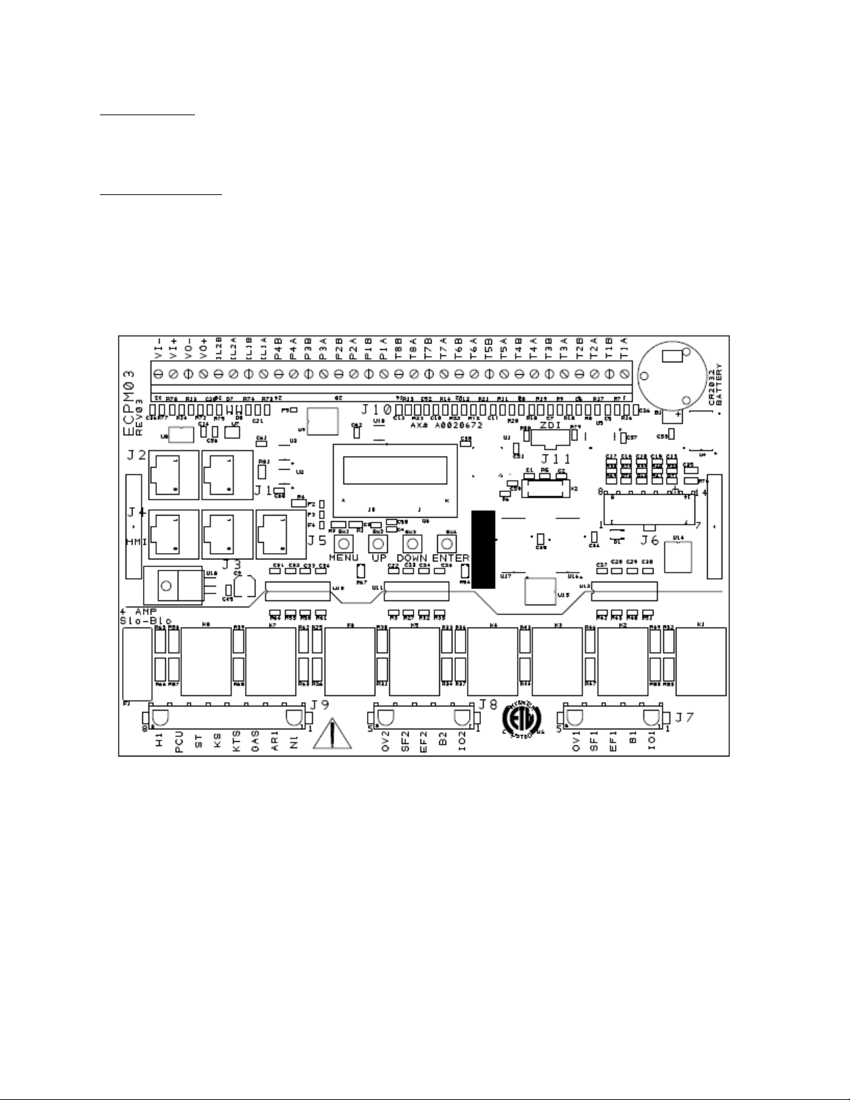
FIELD WIRING: The following is for reference only. All 120 Volt AC field wiring is landed on terminal
blocks, not on the board itself. See Installation section for details. Low voltage class 2 field wiring may be
landed at J3, J4, J5, or J10 connectors only, as indicated by the panel labeling and installation schematic.
Provision for spacing and routing of the field wiring is provided in the panel.
FACTORY WIRING:
The connectors below are intended to be used for factory wiring only by a UL508A panel shop:
J7, J8, J9 are provided for the control of 120 Volt AC relays, contactors, solenoids and shunt trip
breakers. Under no circumstances shall any lighting or motor loads be directly connected to these
connectors.
J1, J2, J6, are reserved for low voltage class 2 factory wiring.
Control Board (ECPM03) diagram
A0023662
May 2014 Rev.5
Page 6
6
INSTALLATION
It is imperative that this unit is installed and operated with the designed airflow and electrical supply in
accordance with these manual and applicable codes. If there are any questions about any items, please
call the service department at 1-866-784-6900 for warranty and technical support issues.
Mechanical
WARNING: DO NOT LIFT CONTROL BY WIRING COMPONENTS
Site Preparation
1. Provide clearance around installation site to safely install equipment into its final position.
Supports must adequately support equipment. Refer to manufacturer’s estimated weights.
2. Consider general service and installation space when locating unit.
Assembly
When the control panel is ordered in a utility cabinet installed on the hood, there is no mechanical
assembly required by the installer. If the control panel is ordered as a wall mounted panel, the enclosure
must be secured to a fixed wall near the exhaust hoods. Be certain to maintain adequate clearance
from excessive heat sources such as appliances to prevent damage of the components.
Room Sensor Installation
A room temperature sensor is provided with the panel. It should be installed in a safe location, free of
influence from external heat sources. It should be indicative of the average kitchen temperature away
from the appliances. The room sensor will always be landed at terminals T1A, T1B on the J10 connector
of the ECPM03.
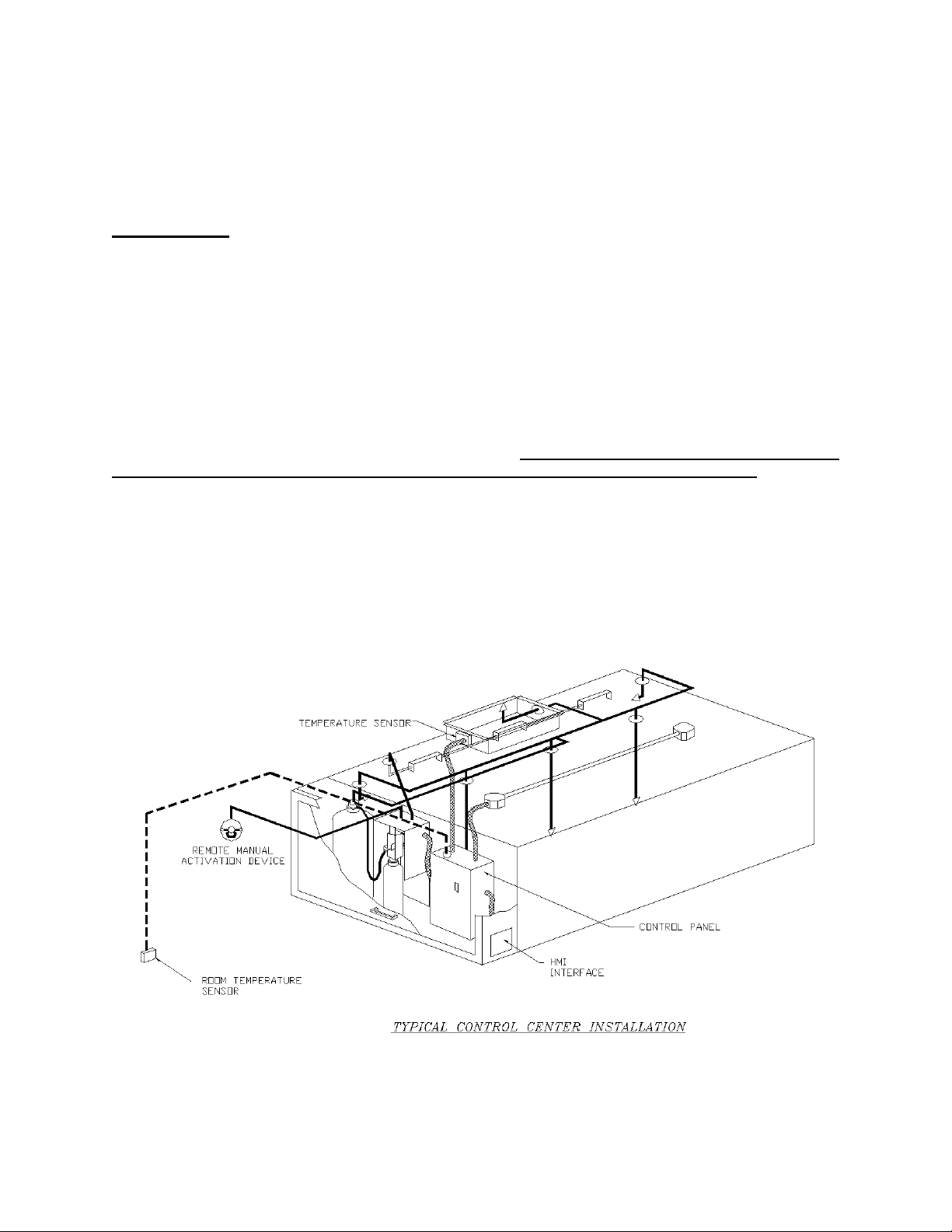
Utility Cabinet Installation (Typical)
A0023662
May 2014 Rev.5
Page 7
7
Mount control panel with adequate
clearance from excessive heat
sources such as appliances to prevent
damage of the components.
IMPORTANT!!
When exhaust duct connections are located and cut in the field, duct temperature probes are
shipped loose in the electrical package enclosure. These must be installed in the duct
immediately above the hood for proper system operation.
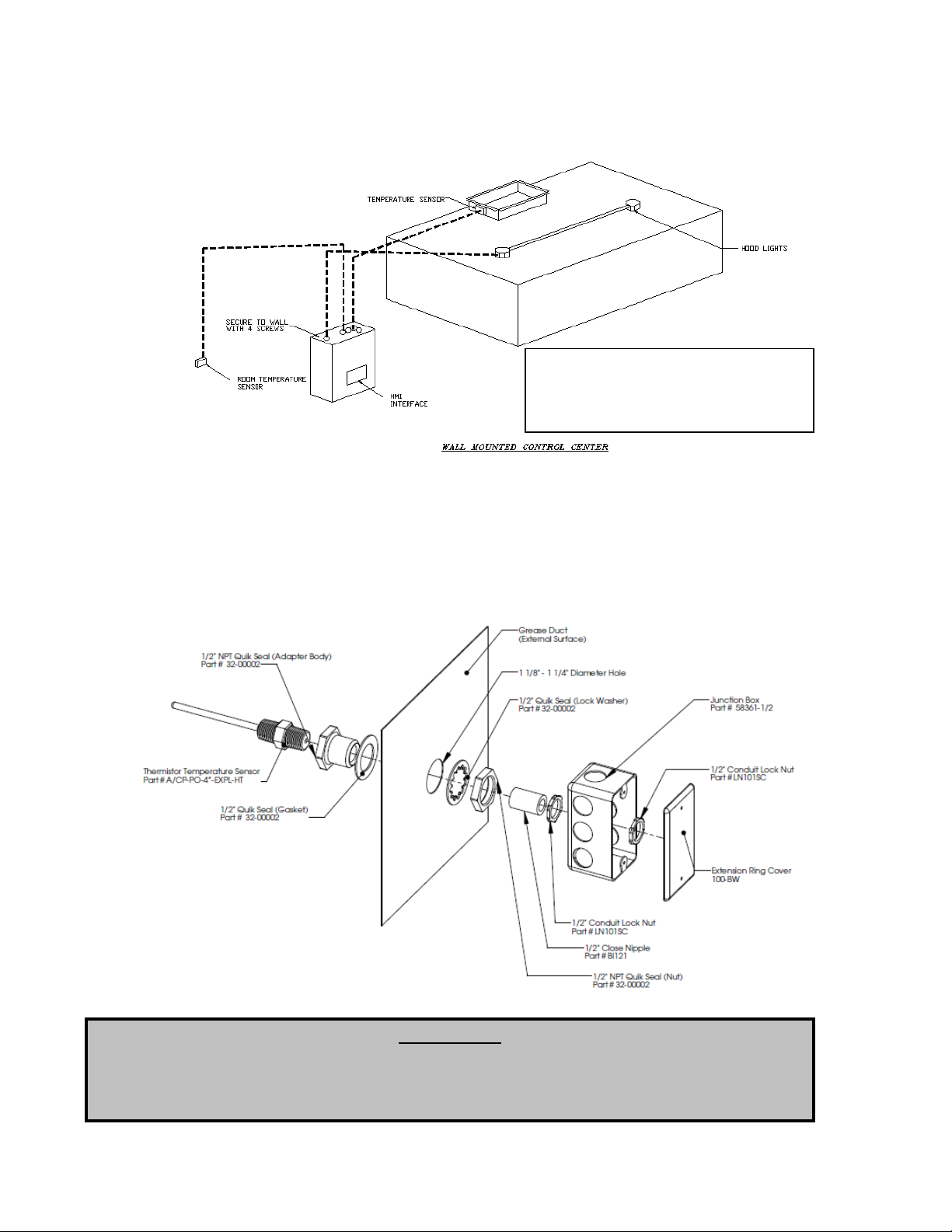
Wall Mount Installation (Optional)
Duct Sensor Installation
When the control panel is ordered, the system typically consists of one duct sensor per hood exhaust
riser. These sensors are typically shipped factory installed in factory assembled hood risers. If the risers
are field cut, the sensor and other components are shipped loose for field installation as shown below. A
hole must be cut in the grease duct, and the quick seal and sensor must be assembled as shown below.
A 2-wire plenum rated thermistor cable (18 gauge typical), run in conduit, should be used to wire the
sensors back to the controller and landed on connector J10 as indicated on the installation schematic.
A0023662
May 2014 Rev.5
Page 8

8
Copper Wire Ampacity
Wire Size AWG
Maximum Amps
14
15
12
20
10
30 8 50 6 65 4 85
WARNING!!
Disconnect power before
installing or servicing control.
High voltage electrical input is
needed for this equipment. This
work should be performed by a
qualified electrician.
Electrical
Before connecting power to the control, read and
understand this entire document. As-built wiring
diagrams are furnished with each control by the factory
and are attached either to the door of the unit or
provided within a paperwork pouch internal to the panel.
Electrical wiring and connections should be done in
accordance with local ordinances and the National
Electric Code, ANSI/NFPA70. Be sure the voltage and
phase of the power supply and the wire amperage
capacity is in accordance with the unit nameplate.
1. Always disconnect power before working on or near this
equipment. Lock and tag the disconnect switch or breaker
to prevent accidental power up.
2. Make certain that the power source is compatible with the
requirements of your equipment. The installation wiring
schematic identifies the proper phase and voltage of the
source breakers.
3. Before connecting control to power source, verify power
line wiring is de-energized.
4. Secure all wiring to prevent contact with sharp objects.
5. Do not kink power cable and never allow the cable to come in contact with oil, grease, hot
surfaces or chemicals.
6. Before powering up the system, make sure that the interior of the control is free of loose debris,
metal shavings, or shipping materials. `
7. If any of the original wire supplied with the system must be replaced, it must be replaced with type
THHN wire or equivalent.
High Voltage Wiring
terminals as indicated on the installation diagram, typically “C1” and “AR1”. C1 is the common
and connects to terminal 1 on the micro-switch. AR1 is the armed state and connects to terminal
2 on the micro-switch. If a CORE fire system is present, this connection is not required.
1. All high voltage wiring shall be terminated
on the right side of the vertical terminal blocks
located on the right hand side.
2. There are multiple electrical power
sources required for this panel. Refer to
Installation diagrams for details.
3. The hood light wiring will also need to be
wired to terminals as indicated on the installation
diagram.
4. If an ANSUL fire system is present, the
fire system micro-switch will need to be wired to
A0023662
May 2014 Rev.5
Page 9

9
Low Voltage Wiring
Low voltage field wiring consists of Duct and Room Temperature sensors, ECM motors, 0-10VDC output,
24VDC input, or Modbus communication over CAT-5 cables for HMI(s) and remote equipment.
Additionally, panels can be ordered with Building Management Options. Refer to the Building
Management Owner’s Manual, if equipped, for low voltage building management wiring requirements.
Low voltage wiring must be run on the left hand side and directly terminated on the terminals located on
the ECPM03 board.
WARNING: Low voltage wires should never be run together with high voltage wires.
1- Room temperature sensor(s): For all installations, at least 1 room temperature sensor must be
installed in a safe location, free of influence from external heat sources. It should be indicative of the
average kitchen temperature away from the appliances. 2-wire 18 AWG thermistor cable must be
used. The room temperature sensor shall be wired according to the installation wiring schematic,
terminals “T1A” and ”T1B”.
2- Duct temperature sensors: For all installations excluding a single hood with factory risers and a
hood mounted panel, duct mounted temperature sensors will need to be wired in the field. 2-wire 18
AWG plenum rated thermistor cable must be used. The temperature sensor should be wired to
terminal blocks as indicated on the installation wiring schematic.
3- HMI is connected to the ECPM03 board through a CAT-5 cable. The HMI has two RJ-45 connectors
connected together for Modbus. The HMI connects to port J4 or J5 (RJ-45) of the ECPM03 board.
The other RJ-45 port of the HMI will typically be occupied by a RJ-45 end-of-line terminator (Part #
EOL120A).
4- Two end-of-line terminators (Part # EOL120A) are included in each panel. They are typically
plugged in at the factory on J3 and either on port J4 or in the back of the first HMI. If another HMI or
other equipment need to connect to a port occupied by an end-of-line terminator, it shall be removed
and place on the HMI or equipment that became connected at the end of the Modbus network.
5- If other pieces of equipment such as PCU Advanced Filter Monitoring (AFM) are connected to this
panel, a cat-5 cable will also be used to run the Modbus communication between these devices. The
cable would be plugged in port J3 of the ECPM03 board. The end-of-line terminators should then be
relocated from J3 to the PCU AFM module.
A0023662
May 2014 Rev.5
Page 10

10
Variable Frequency Drive (VFD) Installation Instructions
Input AC Power
1. Circuit breakers feeding the VFDs are recommended to be thermal-magnetic and fast acting.
They should be sized 1.25 to 1.5 times the input amperage of the drive. Refer to the installation
schematic for breaker sizing.
2. Each VFD should be fed by its own breaker. If multiple VFDs are to be combined on the same
breaker, each drive should have its own protection measure (fuses or miniature circuit breaker)
downstream from the breaker.
3. Input AC line wires should be run in conduit from the breaker panel to the drives. AC input power
to multiple VFDs can be run in a single conduit if needed.
4. The VFD should be grounded on the terminal marked PE.
STOP!
DO NOT connect incoming AC power to output terminals U, V, W. Severe damage to the drive
will result. Input power must always be wired to the L terminal connections (L1, L2, L3)
Output Power
1. Motor wires from each VFD to its respective motor MUST be run in a separate steel
conduit away from control wiring and incoming AC power wiring to avoid noise and
crosstalk between drives.
2. Load reactors: If the distance between the VFD and the motor is great, a load reactor should be
used between the VFD and the motor. The output reactor should be sized accordingly.
208/230V – Load reactor should be used when distance exceeds 250 feet.
460/480V – Load reactor should be ordered when distance exceeds 50 feet.
575V– Load reactor should be ordered when distance exceeds 25 feet.
3. If the distance between the VFD and the motor is between 500 and 1000 FT, a dV/dT filter should
be used.
4. No contactor should be installed between the drive and the motor. Operating such a device while
the drive is running can potentially cause damage to the power components of the drive.
5. When a disconnect switch is installed between the drive and motor, it should only be operated
when the drive is in a STOP state.
Programming
Most VFD parameters are preprogrammed at the factory when proper information about the fan
motors is provided. However the 2 parameters below should be verified in the field during startup.
1. The Drive should be programmed for the proper motor voltage. Refer to parameter P107 in the
“Component Description - Variable Frequency Drive” chapter below.
P107 is set to 0 (Low) if motor voltage is 120 VAC, 208 VAC or 400 VAC. P107 is set to 1 (High)
if motor voltage is 230 VAC, 480 VAC or 575 VAC.
2. The Drive should be programmed for the proper motor overload value. Refer to parameter P108
in the “Component Description - Variable Frequency Drive” chapter below.
P108 is calculated as Motor FLA x 100 / Drive Output Rating (available in table below). P108 is
also indicated on the factory wiring schematic under the “Motor Power Circuit” column.
NOTE: Do NOT adjust minimum and maximum frequency on the VFD. Communication errors will
result between the control board and the VFD. These parameters should be adjusted through the
control panel only.
A0023662
May 2014 Rev.5
Page 11

11
Model Number
Volts
1Ø
input
3Ø
input
HP
Input
Amps
1Ø
120VAC
Input
Amps
1Ø
240VAC
Output
Amps
Breaker
1Ø
120VAC
Breaker
1Ø
240VAC
ESV751N01SXB571
120/
240V X 1 16.6
8.3
4.2
25
15
ESV112N01SXB571
120/
240V X
1.5
20
10 6 30
20
Input
Amps
1Ø
Input
Amps
3Ø
Breaker
1Ø
Breaker
3Ø
ESV371N02YXB571
240V X X
0.5
5.1
2.9
2.4
15
15
ESV751N02YXB571
240V X X 1 8.8 5 4.2
15
15
ESV112N02YXB571
240V X X
1.5
12
6.9 6 20
15
ESV152N02YXB571
240V X X 2 13.3
8.1 7 25
15
ESV222N02YXB571
240V X X 3 17.1
10.8
9.6
30
20
ESV402N02TXB571
240V X 5
18.6
16.5 30
ESV552N02TXB571
240V X
7.5 26
23 40
ESV752N02TXB571
240V X
10 33
29 50
ESV113N02TXB531
240V X
15 48
42 80
ESV153N02TXB531
240V X
20 59
54 90
ESV751N04TXB571
480V X 1
2.5
2.1 15
ESV112N04TXB571
480V X
1.5 3.6 3
15
ESV152N04TXB571
480V X 2
4.1
3.5 15
ESV222N04TXB571
480V X 3
5.4
4.8 15
ESV402N04TXB571
480V X 5
9.3
8.2 15
ESV552N04TXB571
480V X
7.5 12.4
11 20
ESV752N04TXB571
480V X
10 15.8
14 25
ESV113N04TXB531
480V X
15 24
21 40
ESV153N04TXB531
480V X
20 31
27 50
ESV183N04TXB531
480V X
25 38
34 60
ESV223N04TXB531
480V X
30 45
40 70
ESV751N06TXB571
600V X 1 2 1.7 15
ESV152N06TXB571
600V X 2
3.2
2.7 15
ESV222N06TXB571
600V X 3
4.4
3.9 15
ESV402N06TXB571
600V X 5
6.8
6.1 15
ESV552N06TXB571
600V X
7.5 10.2 9
20
ESV752N06TXB571
600V X
10 12.4
11 20
ESV113N06TXB531
600V X
15 19.7
17 30
ESV153N06TXB531
600V X
20 25
22 40
ESV183N06TXB531
600V X
25 31
27 50
ESV223N06TXB531
600V X
30 36
32 60
ACTECH SMV VFD CROSS-REFERENCE TABLE
A0023662
May 2014 Rev.5
Page 12

12
Button
Associated
function
OPERATION
Start-Up Procedure
NOTE: FIRE system must be in ARMED state before proceeding.
1. Once all required connections have been completed as indicated on the installation schematic,
startup can begin. Apply power to the panel. The ECPM03 board and the HMI(s) will power up
and beep. If that is not the case, check all power connections. Verify that there is no alarm
message displayed on any HMI. If there are alarms present, you can press the MUTE button to
silence the alarm and then work to resolve them.
The HMI has 4 buttons; function is displayed adjacent to them on the LCD. These functions will
change depending on the status of the panel. If no text is adjacent to the button, it does not have
a function.
Typically LIGHTS and FANS functions
are shown on the bottom 2 buttons.
The status of those elements is shown
by the shading used inside the box
associated with the function. An empty
box around the FAN function means
that the FANS are turned OFF. A dark
box around the FAN function means
that the FANS are turned ON. The
same applies to LIGHTS.
Note: For the rest of the document, the
term button will be used to refer to
either the actual button or the function
associated with it.
The center two lines of the LCD are reserved for displaying informational or fault messages
When a fault occurs, an audible alarm is triggered and a message is displayed on the HMI(s).
The Audible Alarm can be silenced by pushing the Mute button that appears on the top right
corner.
2. Press the LIGHTS button on the HMI to energize the hood lights. If the lights do not come on,
make sure the light bulbs are installed and/or check the lighting circuit.
3. Press the FANS button on the HMI to energize the fans. Also press the PREP OFF button to run
all exhaust and supply fans.
4. If cooking appliances are connected to an Electric gas valve controlled by the control panel, the
gas valve can be turned ON by pressing the GAS RESET button on the top right corner of the
HMI. The icon will only show if the Gas Valve Option is turned ON under the ECPM03 menu:
Configuration / Misc. Options / Set Gas Valve. , or if a CORE fire protection system is enabled.
5. Turn the Fans off. Turn on the cooking appliance(s) and allow them to reach idle temperature.
The fans should automatically activate as the cooking appliance(s) heats up. The factory set
activation point for duct temperature override of the fan switch is 10 degrees above kitchen room
temperature. Each duct temperature sensor has its own temperature offset setting. These values
should be adjusted based on the cooking appliances and cooking load. Refer to paragraph (e)
under the Configuration section for further details.
A0023662
May 2014 Rev.5
Page 13

13
6. If the controls include the Self Cleaning or CORE Protection Fire System option, a WASH button
will be displayed on the HMI. Push the button to start the wash cycle. Water will be sprayed in the
plenum and duct of the hood and surfactant will be injected at a predetermined frequency. The
wash cycle will stop when the wash timer expires or when the Stop Wash button is pressed.
Make sure Hood filters remain in place during the wash cycle.
NOTE: The hood self-cleaning function will occur automatically at predetermined intervals after the
system detects a hood use period (heated duct sensors). Refer to paragraph (10) to (13) under
miscellaneous configuration section(h) of this manual for adjustment information.
7. If the Proving Interlock Option is enabled, a calibration step is required at startup. Please refer to
the Fan Proving Interlock section below under Functionality for further details about this function.
To perform the calibration, refer to paragraph (e) under the Configuration section.
Sequence of Operation
Preparation Time mode:
Turn on the cooking appliances and allow
Temperature to rise. The exhaust fans will
automatically be energized in Preparation
Time mode at first (Supply off). The
factory set Prep activation point is 7.5
degrees above kitchen room temperature.
LIGHTS will automatically be turned on as
well. LIGHTS can be turned ON and OFF
manually by pressing the LIGHTS button.
Manual method: The FANS button can be
pressed to energize the exhaust fans in
Preparation Time mode (supply off).
Full Modulation:
As the cooking appliances heat up, the
system will go into modulation mode with
supply fan ON. The factory set activation
point for modulation is 10 degrees above
kitchen room temperature. This function
allows the system to meet the
requirements of IMC 507.2.1.1, which
require exhaust fans to activate when
cooking is occurring. The fans take a few
seconds to come up to speed; this setting
is programmed into the panel for a soft
motor startup to prolong the fan motors.
The VFDs should all indicate 48Hz. Once
the cooking process begins, the VFDs will
begin to modulate typically between 48 Hz and 60 Hz based on the Duct temperature. This results in
a 20% reduction in airflow when operation is in low speed, which is equivalent to a 48% reduction in
electrical consumption by the fan motors.
For every exhaust fan, there are two possible factory settings for the temperature control: 450
degree rated hoods are programmed for a modulation range of 5F, while the 600-700 degree rated
hoods are programmed for a modulation range of 45F. All temperature ranges are adjustable as
needed for the application.
Manual Method: The PREP OFF button can be pressed to go into modulation mode and energize the
supply fan. VFDs for all fans will typically run at 48 Hz to start with and modulate based on
temperature from that point on.
A0023662
May 2014 Rev.5
Page 14

14
Max Air Flow:
By manually pressing the MAX AIR button, the fans will run at High Frequency, typically 60 Hz for a
factory set time of 30 minutes. This time is adjustable under the Misc Options section of the
configuration menu. Once the time period has expired or if the MAX AIR button is pressed again, the
VFDs will go back to operating based on the duct temperature.
Cool Down mode:
The fans will go into Cool Down mode when the duct temperature goes below the activation point
minus the temperature hysteresis of 2 degrees. For example, if the activation temperature is at 85 F
and the hysteresis is set to 2F, Cool Down mode will start at 83F.
In Cool Down mode, the exhaust fans will run at the same speed than in Preparation Time mode and
the supply fans will turn off.
NOTE: The hysteresis timer, factory set at 30 minutes, is used to prevent the fans from cycling on
and off too often due to small appliances generating just enough heat to turn on the fans but not
enough to keep them ON for a long time. The Hysteresis Timer will maintain the fans on after they
have been activated by temperature for a minimum time set by this timer, even if the temperature in
the duct cools back down.
Manual Method: If the duct temperature is in the Cool Down mode range, the Hysteresis timer can be
bypassed by pressing the FANS button.
Fans Off:
If the system was in automatic operation, the fans will turn off when the duct temperature goes below
the Prep activation point minus the temperature hysteresis of 2 degrees. For example, if the Prep
activation temperature is at 80F and the temperature hysteresis is set to 2F, then the fans will turn
off at 78F.
NOTE: The Prep hysteresis timer, factory set at 30 minutes, is used to prevent the fans from cycling
on and off too often due to small appliances generating just enough heat to turn on the fans but not
enough to keep them ON for a long time. The Hysteresis Timer will maintain the fans on Cool Down
mode after they have been activated by temperature for a minimum time set by this timer, even if the
temperature in the duct cools back down.
Manual Method: If the duct temperature is below the Cool Down mode range, the Hysteresis timer
can be bypassed by pressing the FANS button. This will also turn the lights off. If the temperature
never went above the Prep activation point and the fans were turned on only by pressing the FANS
button, the pressing the FANS button will directly turn off the fans.
A0023662
May 2014 Rev.5
Page 15

15
Functionality
Fan Control
The control panel controls fans through VFDs. They are used to adjust the speed of 3 phase motors and
frequency is proportional to airflow. There is one VFD for each fan in the system.
Preparation Time Mode
1. This option is enabled by default from the factory.
It can be disabled under Configuration → Factory options.
2. Preparation Time Mode is available for morning operation when appliances are off or when very light
food preparation is performed. Dedicated make-up air will be locked out only allowing the use of
transfer air during this mode. Exhaust fan(s) will run at low CFM while maintaining a balanced kitchen
pressure.
3. Preparation Time mode can be initiated by different means:
By pressing the FANS button on the HMI
When the duct temperature exceeds Prep activation point =Room Temperature + Temp Offset/2
(Factory Default: 7.5 °F).
4. The fans will go back to running in modulation mode if the PREP OFF button is pressed or if the
temperature sensors in the duct measure a temperature above the activation Temperature value.
5. The speed of the exhaust fan(s) in Preparation Time is calculated automatically and is equal to
the speed that will produce the same amount of CFM than the Transfer CFM when the fans are
running in full speed in normal operation. If there is no dedicated supply fan in the system, the
exhaust fans will run at the set High Frequency divided by 4 (typically 15 Hz).
NOTE: If the calculated value falls below the set minimum frequency, then the value will be adjusted
to the lowest allowable frequency.
Hood Lights
1. A control panel can have 1 HMI light switch but potentially controls multiple light circuits. Each
light circuit can feed with a maximum of 1400W. If more than 1400 watts of lights are needed,
additional 15 amp circuits can be brought to the panel. Panel specific lighting limitations are
indicated on the installation schematic.
2. Hood lights can be controlled manually through the LIGHTS button on the HMI. They will also be
automatically turned ON or OFF when the fans assigned to that same fan zone turn ON or OFF.
Manual light switch command on the HMI always takes priority.
Electric Gas Valve Reset
If the Gas Valve option is turned ON or the system is equipped with CORE Fire Protection, an additional
button (GAS RESET/GAS ON) is displayed on the HMI to allow the user to reset or re-energize an electric
gas valve connected to the panel. The gas valve is de-energized at initial startup, when the Fire System is
triggered or in other conditions as well.
Refer to paragraph (h) under Configuration section to turn this option ON or OFF.
High Temperature Automatic Appliance Shutdown
When any of the duct temperature sensors reads a temperature above the Appliance Shutdown
Temperature threshold settings (Factory Default: 250 Degrees °F), any electric gas valve wired to the
panel will shut down and the shunt trip output of the panel will activate. This is intended to prevent
potential fires. The activation threshold set point can be adjusted under Configuration/Fire Options.
Make-Up Air Interlock
When the dedicated supply fan is a Tempered Make-up Air unit, the blower inside the supply unit can be
interlock so that it will not run unless the safety controls (Freezestat, CO sensor, Smoke Detector etc.)
inside the supply fan are armed and until the internal motorized damper has reached its end limit switch.
A0023662
May 2014 Rev.5
Page 16

16
If the signal from the make-up air is not received by the DCV 90 Sec (factory default) after the start signal
is sent to the supply fan, an alarm will appear on the HMI. The DCV panel ships with a jumper between
terminals IL1A and IL1B for supply #1 and IL2A and IL2B for supply #2 if present. The jumper has to be
removed first before wiring the interlock from a make-up air unit.
Appliances Pilot Check Warning:
Every time an electronic gas valve is reset, a warning message will be displayed on the HMI for 1 minute.
A CLEAR button will be displayed on the HMI to clear the warning message and stop the beeps. If after 1
minute, the clear button is not pressed, the message disappears. This message is normal and provided
as a reminder only. There is no need to take any action.
Building Management System (Dry Contact)
1. All controls are equipped with the ability to control the fans via a dry contact BMS interlock.
Terminal IO1 should be energized by closing a dry contact placed between terminals H1 and IO1.
NOTE: the CO Censor option must be disabled for BMS dry contact functionality.
2. Removing the signal from IO1 will typically cause the fans to turn off. However, if the duct
thermostat sensors are hot or if the fans are energized through the fan button on the HMI, then
the fans will continue to run.
NOTE: If the panel is ordered with a digital building management option, such as CASlink,
BACnet, or Lonworks, please refer to the Building Management Owner’s Manual for alternative
fan interlock scheduling.
Minimum Room Temperature
This option is designed to prevent unnecessary automatic fan activation due to excessively cold room
temperatures. This value is adjustable between 50 degrees and 85 degrees. As long as the room
temperature reading is above the Min Room Temp set value, the package will use the actual room
temperature sensor reading to calculate the duct thermostat offset. However, if the room temperature
sensor reading is below the Min Room Temp set value, the package will ignore the actual room temp
reading and use the Min Room Temp set value as a reference instead. This prevents a system from
activating the fans unnecessarily, due to a large gap between room temperature and the hood duct
temperature. This option can also help alleviate fan activation troubles with lower temperature
appliances, which are not satisfying the minimum temperature requirements for fan activation.
Self-Cleaning (Optional)
1. During the wash cycle, water will be sprayed in the plenum and duct and surfactant will be
injected at a set frequency. The wash cycle will stop when the wash timer expires or when the
Wash button is pressed again.
2. The wash timer is factory set to 3 minutes and is adjustable through the Configuration Menu. The
surfactant is injected for 1 second at the start of each minute of Wash. This setting is not
adjustable. If equipped with CORE Fire Protection, the wash timer is not configurable through the
ECPM03 control board. Refer to the CORE Owner’s Manual for further information.
3. Hood filters MUST remain in place during the wash cycle.
4. The wash cycle can be initiated in several ways:
a. Manually, when the WASH button is pressed on the HMI.
b. Automatically, if the following conditions are met
Fans will need to go out of modulation mode either with the FANS button being
pressed or by the duct temperature cooling down and hysteresis value and timer
are met.
The fans will need to have effectively run cumulatively for a period of time longer
than the “Wash Min Fan Runtime” value configured under “Misc Options”.
Preparation Time mode and Cool Down mode fan time do not count towards
runtime. The runtime is reset to zero when the wash cycle is run.
A0023662
May 2014 Rev.5
Page 17

17
The amount of time elapsed since the previous wash cycle is greater than the
“Wash Min Interval time” value configured under “Misc Options”. That elapsed
time is reset to zero when the wash cycle is run.
c. If a Building Management System (BMS) is remotely controlling the fans through the
external input terminal IO1, when the Fans are turned ON and then OFF through the IO1
terminal, granted that the fans are not maintained on by the duct temperature sensors or
the fan button.
d. Through a digital Building Management System. Refer to the Building Management
Owner’s Manual for more information.
5. If the surfactant level is too low, an alarm will be triggered on the HMI. If the wash cycle is
initiated while this alarm is active, water will be sprayed but no surfactant will be injected. Refill
Surfactant as soon as possible for best results. (Refer to Self-Cleaning or CORE Manual for
additional information)
Fan Proving Interlock (Optional) (i.e. Loss of Load Interlock/Airflow Fault Interlock)
1. This function is designed to prevent exhaust fans from running if the supply fans are not running,
which in turn would shut off the cooking equipment. In practical terms, this means that all fans will
shut off along with cooking equipment if any of the exhaust or supply fans are not properly
running. Examples of reasons why a fan would not be properly running are: overload tripped,
broken fan belt, defective motor, disconnect switch off, etc.
2. This function requires calibration, which can be performed through the Calibration setting on the
ECPM03 LCD.
3. If this option is enabled, the load on all the exhaust and supply fans is constantly monitored. If the
load for an exhaust fan or the load for a supply fan drops below the threshold calculated after
calibration for more than the 35 sec, all exhaust and supply fans will shut down.
4. If an electric gas valve and shunt trip are attached to the system, they will shut down as well.
5. To reset the system after a Proving fault, press the Fault Reset button on the HMI.
CORE Protection Fire System (Optional)
1. If a CORE Protection Fire system is connected to the control panel, alarms from the CORE
system will automatically be displayed on the HMI.
2. Multiple CORE systems can be connected to the same control panel. Refer to the CORE Manual
for setup of CORE Interlock Network addressing to prevent communication conflicts.
PCU Advanced Filter Monitoring (AFM) (Optional)
1. If a PCU AFM is connected to the control panel through Modbus, alarms from the PCU will
automatically be displayed on the HMI.
2. To connect the AFM system to the HMI, run a CAT-5 connection from terminal J3 to the RJ45
port on the PCU AFM internal to the PCU. This is outlined in the installation schematics.
3. Up to 8 PCU AFM can be connected to the same Control panel. . Note that each additional PCU
AFM must be assigned a unique Modbus address. Refer to the PCU AFM manual for more
information. Note that each additional PCU AFM must be assigned a unique Modbus address.
Refer to the PCU AFM manual for more information.
Electric Gas Valve Follow Fans (optional)
This option is only available when an electric gas valve is enabled. If this option is ON, the gas valve is
shut off whenever the fans are off and requires a reset when the fans are turned ON. This is meant to
prevent gas cooking appliances to run when the fans are off and is only required in some jurisdictions.
This option can be enabled under Configuration/Misc Options/Gas Follow Fans. Factory Default Setting is
OFF. NOTE: Appliance pilots must be relit after each fan cycle when this option is enabled.
A0023662
May 2014 Rev.5
Page 18

18
Shunt Trip Follow Fans (Optional)
If this option is ON, the shunt trip will be energized whenever the fans are off. This is meant to prevent
electric cooking appliances from running when the fans are off and is only required in some jurisdictions.
This option can be enabled under Configuration/Misc Options/Shunt trip Follow Fans. Factory Default
Setting is OFF.
Dimmable HMI (Optional)
This option allows the backlight on all HMIs to turn off whenever a timer is satisfied. The timer is refreshed
every time the HMI button is pressed. This option is factory set to be disabled, and can be enabled under
Configuration/Misc Options/ Set HMI Dimming.
CO Censor Input (Optional)
If a CO Sensor is wired to the DCV and the CO sensor is triggered, all exhaust fans will be turned ON and
will ramp up to their high speed. All supply fans will be turned OFF, the gas valve will be shut off, and the
shunt trip will be energized. This option is only accessible through terminal IO1. Terminal IO1 should be
energized by closing a dry contact placed between terminals H1 and IO1, also CO sensor should be
enabled; otherwise, the IO1 terminal will function as BMS input. Factory Default Setting is OFF.
PCU CORE ONLY (Optional)
This option can only be enabled if CORE Hood is disabled. If this option is enabled, all the faults
occurring on a connected PCU CORE system will be displayed on the HMI. A cat5 cable will be needed
to connect the PCU CORE to the slave side of the network, typically J3. Factory Default Setting is OFF.
Energy Saving Graph (optional)
The % Savings graph on the HMI provides information on how much fan energy is saved by the system
when running the fans at lower speed. It is calculated based on the actual Kilowatts measured from each
Variable Frequency Drive controlling the fans. However, it doesn’t include the additional savings resulting
from the lower CFM of Make-up air and HVAC air that require heating or cooling. This option is factory set
to be enabled, and can be disabled under Configuration/Misc Options/Hide Energy Savings.
A0023662
May 2014 Rev.5
Page 19

19
Configuration and Diagnostics
Security
1. To access the Configuration / Factory, the password 1111 must be used.
2. To access the Configuration / Fire Options, the password 1234 must be used.
Setup Options
The ECPM03 board allows the user to monitor the system and configure a broad range of options
associated with the functionality of the system. Monitoring is done through the setup menus on the
ECPM03 LCD as shown above. Configuration is done through the HMI after calling for Configuration
through the ECPM03 menu.
Below the ECPM03 LCD are 4 buttons for navigation: MENU, UP, DOWN, ENTER. When in configuration
mode, the four buttons on the HMI will be labeled the same. See picture above.
The MENU button typically takes you up one level in the menu tree while the ENTER button takes you
down one level. UP and DOWN navigate through the same level of the menu tree and also allow the user
to change the value of a parameter.
After changing some parameters in the configuration menus, the user needs to press MENU multiple
times on the HMI until the screen displays the message “Saving. Wait for reboot” As indicated, the
processor will reboot. This allows the board to correctly process the parameters changed.
NOTE: a reboot of the board will cause the electric gas valve (if equipped) to shut off. Confirm that
gas/pilot lights are re-lit if necessary. It will also cause the VFDs to stop if not in Auto mode.
The 4 items below can be accessed through the ECPM03 LCD:
a. Display System Information
Starting from the Main menu, press the DOWN button, press DOWN again. Screen displays “Info”.
Press the ENTER button. Screen displays “Fault History”. Press DOWN to View the Version number.
Press DOWN to view the package Type, which should be “DCV”.
b. Display Fault History
Starting from the Main menu, press the DOWN button, press DOWN again. Screen displays “Info”.
Press the ENTER button. Screen displays “Fault History”. Press ENTER. Press UP and DOWN to
scroll through the fault history, with 1 being the most recent fault. To clear the fault history, please
ENTER and press ENTER again when prompted “Clear Fault History”. Or press MENU to go back
without clearing.
A0023662
May 2014 Rev.5
Page 20

20
c. Display temperature readings
Starting from the Main menu, press the DOWN button. Screen displays “Temperatures”. Press the
ENTER button. Press the UP and DOWN buttons to view all temperatures measured by the room and
duct temperature sensors.
d. Display Fan Monitoring data: Fan Frequencies and Motor Amps
Starting from the Main menu, press the DOWN button until the screen displays “Monitoring”. Press
the ENTER button. Press the UP and DOWN buttons to alternate between “Fan Frequencies” and
“Motor Amps”. Press enter for either one to view Frequency of each VFD or amps drawn by the motor
on each fan.
e. Fan Proving Interlock: Calibration
If the Fan Proving Interlock option is enabled, Calibration is required at startup. To perform
calibration, make sure Test and Balance has been performed on the entire system first. Filters should
be in place.
Starting from the Main menu, press DOWN until the screen displays “Calibration”. Press ENTER. The
screen should display “Proving Calib. Calibrate?” Press ENTER again to start the Calibration process
which takes about 40 sec. Press MENU once when calibration is complete.
If Calibration is unsuccessful, the message “Calibration Fail” will appear. Make sure the VFDs are
running and the MUA interlock signal is wired correctly to ILxA ILxB.
All the items below are for Configuration and are accessed by putting the HMI into Configuration mode.
To do this, starting from the Main menu on the ECPM03 LCD, press the MENU button. Screen displays
“Configuration” Press the ENTER button. Screen will display “Config Menu
on HMI”. From there, the rest can be done on the HMI.
f. Configure Temperature Sensor Assignments
Starting from the Main menu of HMI, screen displays “Temp Sensor
Assignment”. Press ENTER. Screen displays “Select Temp Sens to
assign: 1”.
To navigate to another Temperature sensor, press the UP button. To
configure the assignment for a Temperature Sensor, press ENTER.
1. For Temperature sensor 1, the options are either to follow the room sensor wired to terminal T1A,
T1B (“Room Temp 1”) or to assign a preset room temperature (75°F by default). Press UP or
DOWN to choose the proper option. Press MENU to confirm the selection. To change the default
preset value, press the ENTER button when displaying the Preset Temperature. Press UP or
DOWN to change the preset value. Press MENU multiple times to get out to main menu.
2. For Temperature sensor 2 and above, the options are either control or monitor. To control the fan
the choice should be capture volume or riser followed by the fan number. To monitor the
temperature. The decision should be one out of the list: Auxiliary Temp, Hood Coil Input, Hood
Coil Output, PSP Discharge, or ACPSP Discharge.
Press MENU multiple times to get back to the main menu or one more time to reboot the processor.
g. Configure Temperature Sensor Offset values (Factory Default: 15 Degrees °F)
Starting from the Main menu of HMI, press DOWN once so screen displays “Temp Sensor Offset”.
Press ENTER. Screen displays “Select Temp Sens to Offset: 2”
Press UP or DOWN to navigate between the different Duct Temperature sensors. Press ENTER to
select one. Then press UP or DOWN to adjust the offset Temperature.
Press MENU multiple times to get back to the main menu or one more time to reboot the processor.
A0023662
May 2014 Rev.5
Page 21

21
h. Configure Misc. Options:
1. Enable Electric Gas Valve control
This option will be enabled by default if the system is equipped with CORE Protection Fire
system.
Starting from the Main menu of HMI, press DOWN or UP until the screen displays “Misc Options”.
Press ENTER. Press UP or DOWN until the screen displays “Set Gas Valve”. Press ENTER.
Press UP or DOWN to turn this option ON or OFF. Press ENTER.
Press MENU multiple times to get back to the main menu or one more time to reboot the
processor.
2. Enable Electric Gas Valve Follow Fans (Factory Default: OFF)
This option is only available when Gas Valve is turned ON or CORE is enabled.
Starting from the Main menu of HMI, press DOWN or UP until the screen displays “Misc Options”.
Press ENTER. Press UP or DOWN until the screen displays “Gas Valve Follow Fans”. Press
ENTER. Press UP or DOWN to turn this option ON or OFF.
Press MENU multiple times to get back to the main menu or one more time to reboot the
processor
3. Enable Shunt Trip Follow Fans (Factory Default: OFF)
Starting from the Main menu of HMI, press the MENU button. Press DOWN or UP until the
screen displays “Misc Options”. Press ENTER. Press UP or DOWN until the screen displays
“Shunt Trip Follow Fans”. Press ENTER. Press UP or DOWN to turn this option ON or OFF.
Press MENU multiple times to get back to the main menu or one more time to reboot the
processor
4. Adjust the Temperature Hysteresis (Factory Default: 2°F):
The hysteresis is used to prevent the fans from cycling ON and OFF when the temperature in the
duct is near the activation value. The fans will turn ON when the duct temperature exceeds the
activation value, but they will only turn off when the duct temperature goes below the activation
temperature minus the temperature hysteresis. For example, if the activation Temperature is at
85 °F and Temperature Hysteresis is set to 2 °F, the fans will turn ON at 85 °F and will turn OFF
at 83 °F.
Starting from the Main menu of HMI, press DOWN or UP until the screen displays “Misc Options”.
Press ENTER. Screen displays “Set Temp Hyst”. Press ENTER. Press UP or DOWN to adjust
the Hysteresis value. Press ENTER
Press MENU multiple times to get back to the main menu or one more time to reboot the
processor.
5. Adjust the Hysteresis Timer (Factory Default: 30 min):
The hysteresis is used to prevent the fans from cycling on and off too often due to small
appliances generating just enough heat to turn on the fans but not enough to keep them ON for a
long time. The Hysteresis Timer will maintain the fans on after they have been activated by
temperature for a minimum time set by this timer, even if the temperature in the duct cools back
down.
Starting from the Main menu of HMI, press DOWN or UP until the screen displays “Misc Options”.
Press ENTER. Press UP or DOWN until the screen displays “Set Hyst Timer”. Press ENTER.
Press UP or DOWN to adjust the Timer value. Press ENTER
Press MENU multiple times to get back to the main menu or one more time to reboot the
processor.
6. Adjust the Max Air Time (Factory Default: 30 min):
Starting from the Main menu of HMI, press DOWN or UP until the screen displays “Misc Options”.
Press ENTER. Press UP or DOWN until the screen displays “Set Max Air Time”. Press UP or
DOWN to adjust the Timer value. Press ENTER.
Press MENU multiple times to get back to the main menu or one more time to reboot the
processor.
A0023662
May 2014 Rev.5
Page 22

22
7. Set 0-10VDC output (Factory Default: Exhaust CFM Ratio):
In addition to each variable frequency drive (VFD) in the DCV system providing a 0-10 VDC
analog output from its terminals 30 and 2 directly proportional to its Fan Speed Ratio (Fan
Frequency / Fan High Frequency), the ECPM03 also offers a 0-10VDC output from terminals VO-
and VO+. This output can be configured depending on the type of signal needed by the building
management system or the equipment receiving it.
Three (3) types of signal are available:
- Total Exhaust CFM Ratio = Total Operating Exh CFM / Total Design Exh CFM
- Total Supply CFM Ratio = Total Operating Sup CFM / Total Design Sup CFM
- Total Transfer CFM Ratio = Total Operating Transfer CFM / Total Design Transfer CFM
Total Exhaust CFM Ratio could be sent to a Roof Top Unit providing make-up air to the hood.
Total Transfer CFM Ratio could be sent to a HVAC unit indicating how much transfer air is
needed for the kitchen. This selection takes in consideration the Preparation Time Mode where
the same amount of transfer air is used as when the fans are all running at maximum speed.
Total Supply CFM Ratio is only available if a Supply fan is present in the DCV system. In
Preparation Time, Total Supply CFM Ratio would be 0.
Starting from the Main menu of HMI, press DOWN or UP until the screen displays “Misc Options”.
Press ENTER. Press UP or DOWN until the screen displays “0-10VDC output”. Press UP or
DOWN to set the option needed. Press ENTER.
Press MENU multiple times to get back to the main menu or one more time to reboot the
processor.
8. Fan Proving Interlock: Proving Percentage (factory default 80%)
If the Fan Proving Interlock option is enabled, the Proving Percentage setting is available.
Its value can range between 50% and 100%. The greater the ratio, the tighter the limits will be for
fault detection, which also means the greater likelihood of false positive.
Starting from the Main menu of HMI, press DOWN or UP until the screen displays “Misc Options”.
Press ENTER. Press UP or DOWN until the screen displays “Set Proving Percent”. Press
ENTER. Press UP or DOWN to adjust the ratio value. Press ENTER. Press MENU multiple times
to get back to the main menu or one more time to reboot the processor.
9. Adjust Wash Time (Min) (Factory Default: 3 min):
This option is available if the control system includes self-cleaning option from the factory. The
wash time value is setup in minutes with a maximum value of 30 minutes.
Starting from the Main menu of HMI, press DOWN or UP until the screen displays “Misc Options”.
Press ENTER. Press UP or DOWN until the screen displays “Set Wash Time”. Press ENTER.
Press UP or DOWN to adjust the time value. Press ENTER
Press MENU multiple times to get back to the main menu or one more time to reboot the
processor.
10. Adjust Wash Frequency (Hz) (Factory Default: 15 Hz):
This option is available if the control system includes self-cleaning option from the factory. This
value is the frequency at which all exhaust fans will run in wash mode. The Supply fan will be
stopped during Wash.
Starting from the Main menu of HMI, press DOWN or UP until the screen displays “Misc Options”.
Press ENTER. Press UP or DOWN until the screen displays “Set Wash Frequency”. Press
ENTER. Press UP or DOWN to adjust the frequency value. Press ENTER
Press MENU multiple times to get back to the main menu or one more time to reboot the
processor.
A0023662
May 2014 Rev.5
Page 23

23
11. Set Wash Min Fan Runtime (Factory Default: 480 min):
This option is available if the control system includes self-cleaning option from the factory. Its
maximum value is 1440 minutes or 24 hours. Refer to the Self-Cleaning Section under
Functionality for more details about this option.
Starting from the Main menu of HMI, press DOWN or UP until the screen displays “Misc Options”.
Press ENTER. Press UP or DOWN until the screen displays “Set Wash Min Fan Runtime”. Press
ENTER. Press UP or DOWN to adjust the time value. Press ENTER.
Press MENU multiple times to get back to the main menu or one more time to reboot the
processor.
12. Set Wash Min Interval Time (Factory Default: 720 min):
This option is available if the control system includes self-cleaning option from the factory. Its
maximum value is 1440 minutes or 24 hours. Refer to the Self-Cleaning Section under
Functionality for more details about this option.
Starting from the Main menu of HMI, press DOWN or UP until the screen displays “Misc Options”.
Press ENTER. Press UP or DOWN until the screen displays “Set Wash Min Interval time”. Press
ENTER. Press UP or DOWN to adjust the time value. Press ENTER. Press MENU multiple times
to get back to the main menu or one more time to reboot the processor.
13. Adjust the number of PCU Advanced Filter Monitoring (AFM) Units
If PCU AFM units are connected to the control panel (through Modbus), the number of units has
to be adjusted through this parameter. Refer to the PCU AFM manual for additional information
on how to setup the PCU AFM unit number at the unit control panel.
Starting from the Main menu of HMI, press DOWN or UP until the screen displays “Misc Options”.
Press ENTER. Press UP or DOWN until the screen displays “Set Number of PCU AFM”. Press
ENTER. Press UP or DOWN to adjust the number of units. Press ENTER.
Press MENU multiple times to get back to the main menu or one more time to reboot the
processor.
14. Set External input to interlock Fans option
This option is used when the DCV panel is used in conjunction with a third party panel handling a
wash sequence. Based on the value selected for this option, the fans will behave differently when
an input is received on the OV2 terminal.
- OFF: no action.
- WASH CYCLE: Exhaust fans will run at the wash frequency and supply fans will stop.
This is used when a third party panel is washing the hood.
- DRY CYCLE: Exhaust fans will run at High frequency and supply fans will stop. This is
used when a third party panel requires the exhaust fan to run at full speed for drying
purposes.
15. Set HMI Dimming (Factory Default :OFF)
Starting from the Main menu of HMI, press DOWN or UP until the screen displays “Misc Options”.
Press ENTER. Press UP or DOWN until the screen displays “Set HMI Dimming”. Press ENTER.
Press UP or DOWN turn this option ON or OFF. Press ENTER
Press MENU multiple times to get back to the main menu or one more time to reboot the
processor.
16. Set Dim Delay Time (Factory Default: 60sec)
This option is only accessible when HMI Dimming is ENABLED. It allows the user to modify the
time for which the backlight of the HMI remains on before it will turn off. The Dim Delay Time is
factory set to 60 sec, and is refreshable every time a button on the HMI is pressed. The Dim
Delay Time is adjustable between 10sec and 5 minutes.
Starting from the Main menu of HMI, press DOWN or UP until the screen displays “Misc Options”.
Press ENTER. Press UP or DOWN until the screen displays “Set Dim Delay Time”. Press
ENTER. Press UP or DOWN to adjust the time value. Press ENTER
A0023662
May 2014 Rev.5
Page 24

24
Press MENU multiple times to get back to the main menu or one more time to reboot the
processor.
17. Set Min Prep Frequency(Factory Default: 10Hz)
This option is only displayed when Prep Time Mode is enabled. Its maximum value is the
minimum of the low frequencies of all the fans controlled by the package and minimum value is
5Hz.
Starting from the Main menu of HMI, press DOWN or UP until the screen displays “Misc Options”.
Press ENTER. Press UP or DOWN until the screen displays “Set Min Prep Frequency”. Press
ENTER. Press UP or DOWN to adjust the Min Frequency. Press ENTER
Press MENU multiple times to get back to the main menu or one more time to reboot the
processor.
18. Hide Energy Savings(Factory Default: NO)
Starting from the Main menu of HMI, press DOWN or UP until the screen displays “Misc Options”.
Press ENTER. Press UP or DOWN until the screen displays “Hide Energy Saving”. Press
ENTER. Press UP or DOWN to choose YES or NO. Press ENTER
Press MENU multiple times to get back to the main menu or one more time to reboot the
processor.
19. CO Sensor Input(Factory Default:OFF)
Starting from the Main menu of HMI, press UP or DOWN until the screen displays “Misc Options”.
Press ENTER. Press UP or DOWN until the screen displays “CO Sensor Input”. Press ENTER.
Press UP or DOWN to choose: ON or OFF. Press ENTER
Press MENU multiple times to get back to the main menu or one more time to reboot the
processor.
20. Set Min Room Temp(Factory Default: 50 Degrees °F)
Starting from the Main menu of HMI, press UP or DOWN until the screen displays “Misc Options”.
Press ENTER. Press UP or DOWN until the screen displays “Set Min Room Temp”. Press
ENTER. Press UP or DOWN to adjust the set value. Press ENTER
Press MENU multiple times to get back to the main menu or one more time to reboot the
processor.
21. PCU CORE Only(Factory Default: OFF)
Starting from the Main menu of HMI, press UP or DOWN until the screen displays “Misc Options”.
Press ENTER. Press UP or DOWN until the screen displays “PCU CORE Only ON/OFF”. Press
ENTER. Press UP or DOWN to choose: ON or OFF. Press ENTER
Press MENU multiple times to get back to the main menu or one more time to reboot the
processor. NOTE: This will not be present if HOOD CORE is enabled under the Factory Options
menu.
i. Set IO1 Delay Time (Factory Default: 0 min)
This option is intended for applications that require the fans to keep running for a specific amount of
time right after the BMS signal is turned OFF. The delay time value is set in minutes with a maximum
value of 15 minutes. The fans will remain ON for the set time after the BMS is de-energized.
Starting from the Main menu of HMI, press UP or DOWN until the screen displays “Misc Options”.
Press ENTER. Press UP or DOWN until the screen displays “Set IO1 Delay Time”. Press ENTER.
Press UP or DOWN to adjust the set value. Press ENTER
Press MENU multiple times to get back to the main menu or one more time to reboot the processor.
A0023662
May 2014 Rev.5
Page 25

25
j. Configure Fan Options
This sub-menu contains all options related to Fan configuration.
Starting from the Main menu of HMI, press DOWN or UP until the screen displays “Fan Options”.
Press ENTER. Press UP or DOWN until one of the options below is displayed. Press ENTER to
access that option. Press UP or DOWN to select the fan (EXH1, EXH2, SUP1 etc.). Press ENTER.
Press UP or DOWN to change the value of that option for that fan. Press ENTER Press UP or DOWN
to select another fan or press MENU and then UP or DOWN to move on to the next option.
1. Set Fan Direction (Factory Default: FWD):
If the fan is running in the wrong direction at startup, the direction can be changed here without
having to change the wiring of the 3-phase motor.
Fan direction can be changed between Forward (FWD) and Reverse (REV).
2. Set Fan Design CFM
This is the design CFM value specified for each fan. This value is internally matched to the High
Frequency set for this fan and used to calculate the Supply fan frequency, as well as the
Preparation Time Frequency. This value should be adjusted after Test and Balance has been
performed on the hood.
NOTE: Changing this value will NOT automatically change the actual CFM exhausted by the fan.
This is achieved by changing the High Frequency. This value is to report to the Controller what
the design CFM is so it is used for internal calculation.
3. Set High Frequency
The High Frequency is the maximum frequency at which an exhaust fan will be running in
modulation mode. This corresponds to the design CFM of the exhaust fan. This value can be
adjusted during Test and Balance of the hood, if needed to adjust the amount of CFM exhausted
at the hood when the adjustment is smaller than what can be achieved with a pulley change. The
value can be increased up to 80 Hz and lowered down all the way to the Low Frequency setting.
4. Set Low Frequency (Exhaust fans only)
The Low Frequency is the minimum frequency at which an exhaust fan will be running in
modulation mode. The fan can still run slower in Wash mode or in Preparation Time. By default
this value is set to 48 Hz which represents a minimum of 80% of full speed when High Frequency
is left at 60 Hz. 20% is the recommended modulation value to ensure capture and containment at
the hood during cooking. Lowering this value is possible but should be carefully evaluated.
5. Set Modulation (Exhaust fans only)
This value is used to calculate the high temperature of the modulation range for each exhaust
fan. The low temperature is the value at which the fan will come on automatically and at which it
runs at the Low Frequency value. Low temperature = Room temperature measured + Temp
Offset. The high temperature is the value at which the fans are running at full speed or High
Frequency. High temperature = Room temperature measured + Temp Offset + Modulation
Range.
Press MENU multiple times to get back to the main menu or one more time to reboot the processor.
A0023662
May 2014 Rev.5
Page 26

26
k. Configure the Fire Options
This sub-menu is Password protected and changes should not be made after passing an
inspection.
Starting from the Main menu of HMI, press DOWN or UP until the screen displays “Fire Options”.
Press ENTER. When prompted, enter the password specified under the security section of this manual
above. Press UP or DOWN until one of the options below is displayed. Press ENTER to access that
option. Press UP or DOWN to change the value of that option. Press ENTER to move on to the next
option.
1. Exhaust On in Fire (Factory Default: ON): When this option is turned ON, the exhaust fans will be
turned ON in a fire condition. If the option is turned OFF, the exhaust fans will stay in whatever
state they were before the fire condition.
2. Lights Out in Fire (Factory Default: ON): When this option is turned ON, the hood lights will be
turned OFF in a Fire condition. If the option is turned OFF, the hood lights will stay in whatever
state they were before the fire condition.
3. Supply Off in Fire (Factory Default: OFF): When this option is turned OFF, the Supply fans will be
turned OFF in a Fire condition. If the option is turned ON, the Supply fans will turn ON in a fire
condition.
4. Appliance Shutdown Temp Threshold (Factory Default: 250 Degrees °F): When any of the duct
temperature sensors reads a temperature above that threshold, the gas valve shuts down and
shunt trip output is activated.
Press MENU multiple times to get back to the main menu or one more time to reboot the processor.
l. Configure Factory Options
This sub-menu is password protected and should only be accessed by the factory since all the
settings under it are directly related to the hardware configuration of the system. Only access this
page if instructed by the manufacturer.
Starting from the Main menu of HMI, press the DOWN button until the screen displays “Factory”.
Press ENTER. When prompted, enter the password specified under the security section of this
manual above. Press UP or DOWN until one of the options below is displayed. Press ENTER to
access that option. Press UP or DOWN to change the value of that option. Press ENTER to move on
to the next option.
1. Set Number of Temp Sensors
This includes all Room Temperature Sensors and Duct Temperature sensors conneted to the
ECPM03 board. Valid values range from 2 to 32.
2. Set Number of Exhaust Fans:
This defines the number of exhaust VFDs controlled the system. There can be up to 8 exhaust
fans.
3. Set Number of Supply Fans
This defines the number of exhaust VFDs controlled the system. There can be up to 2 supply
fans.
NOTE: Based on the number of Exhaust fans, number of Supply fans, and size of VFDs you may be
required to use an expansion box.
A0023662
May 2014 Rev.5
Page 27

27
4. Set Number of Fan Switches
This defines the number of fan switches controlled by the system. There can be 0 or 1 fan
switch. A fan switch will be displayed on the HMI accordingly. If 0 is selected, the fans will be
only controlled by the temperature sensors.
5. Set Number of Light switches
This defines the number of hood light switches controlled by the system. There can be 0, or 1
light switch. A light switch will be displayed on the HMI accordingly.
6. Set Proving Interlock
This option enables or disables the Fan Proving Interlock. Refer to the Fan Proving Interlock
paragraph under Functionality for further details. If this option is enabled, Proving calibration is
required. Refer to paragraph e under Setup Options.
7. Set Hood CORE
This option determines if the system is connected to a CORE Fire Protection system.
8. Set Wash
This option determines if the system includes a self-cleaning option. This option will not be
available if CORE is enabled.
9. Set Prep Time Enable
This option enables or disables the Preparation Time mode. Refer to the Preparation Time Mode
paragraph under Functionality for further details.
10. Set KTS
This option determines if a Kill switch or Tamper switch are connected to the system. If this
option enabled, the input KTS shall be maintained energized for normal cooking operations. If
KTS is deenergized, an electric gas valve connected to the system would drop and the shunt trip
output will be energized.
11. Fan Controller type
For each Fan, this option determines the type of Controller being used. Two (2) options are
available: 571 and 531. If 571 is selected, the ECPM03 will communicate to a VFD with part
number ending in 571. Typically these VFDs are 10 HP and below. If 531 is selected, the
ECPM03 will communicate to a VFD with part number ending in 531. Typically these VFDs are
15 HP and above.
Press MENU multiple times to get back to the main menu or one more time to reboot the processor.
A0023662
May 2014 Rev.5
Page 28

28
Component Description
Variable Frequency Drive
Variable frequency drives change the speed of 3 phase motors by changing the
frequency signal sent to the motor. There is one variable frequency drive for each
fan in this system. 2 RJ-45 plugs are used to connect the drives to each other and
to the ECPM03 controller through CAT-5 cables.
Variable Frequency Drive Parameters
Variable frequency drive parameters can be changed with the buttons on the face
of the drive. Only parameters P107 (Line voltage Selection) and P108 (Motor
Overload) should be adjusted in the field if needed. All other settings can be adjusted through the HMI.
P107 is set to 0 (Low) if motor voltage is 120 VAC, 208 VAC or 400 VAC. P107 is set to 1 (High) if motor
voltage is 230 VAC, 480 VAC or 575 VAC.
P108 is calculated as Motor FLA x 100 / Drive Output Rating (available in the VFD cross reference table
under the Electrical Installation chapter above).
To enter the PROGRAM mode to access the parameters:
1. Press the Mode (M) button.
2. If no password is required, the display will read “P100”. If it prompts for a password (PASS), use
the Up and Down buttons to scroll to the password value (the factory default password is “0225”)
and press the Mode (M) button. Once the correct password is entered, the display will read
“P100”, which indicates that the PROGRAM mode has been accessed at the beginning of the
parameter menu.
3. Use the Up and Down buttons to scroll to the desired parameter number.
4. Once the desired parameter is found, press the Mode (M) button to display the present parameter
setting. The parameter value will begin blinking, indicating that the present parameter setting is
being displayed. The value of the parameter can be changed by using the Up and Down buttons.
5. Pressing the Mode (M) button will store the new setting and also exit the PROGRAM mode. To
change another parameter, press the Mode (M) button again to re-enter the PROGRAM mode. If
the Mode button is pressed within 1 minute of exiting the PROGRAM mode, the password is not
required to access the parameters. After one minute, the password must be re-entered in order to
access the parameters again.
P500 parameter provides a history of the last 8 faults on the drive. It can be accessed without getting into
PROGRAM mode.
ECPM03 board
The ECPM03 is the main brain of the system. It receives all the digital and
analog inputs and delivers the digital outputs and sends out messages to
other devices.
Connector Descriptions
J1, J2: Modbus slave network connectors feed through RJ45s,
which conform to the Modbus pin out for RS485 2 wire differential
Modbus RTU standard. See http://www.modbus.org. Modbus
communication is not configured for third party integration without
additional components.
J3, J4, J5: Modbus master network connectors, feed through RJ45s, which conform to the
Modbus pin out for RS485 2 wire differential Modbus RTU standard. J4 and J5 are the only RJ45
port on the ECPM03, which serves as a power source for HMI(s).
J6: Factory low voltage connections
A0023662
May 2014 Rev.5
Page 29

29
o Pin 1 positive side of the 24 Volt DC input to the board
o Pin 2 – 7 Open collector outputs, 100ma max each, suitable for driving 24VDC relays or
indicator lamps.
o Pin 8 – 12 4-20ma current inputs. 150 Ohm impedance to 24 VDC ground pin 14.
o Pin 13 Chassis ground connection, this pin connects to the 24VDC ground through a
paralleled 1000pf 2000V cap and a 100k Ohm 1/4W resistor.
o Pin 14 negative side of the 24 volt DC power input (ground or common side of the low
voltage circuitry)
J7: 120 VAC control connector for factory wiring
o Pin 1 IO1, BMS input, can detect the presence of 120VAC, this forces the fans on.
o Pin 2 B1, input, this pin can detect the presence of 120VAC.
o Pin 3 EF1, output and input, this pin can source 120VAC and detect the presence of
120VAC
o Pin 4, SF1, output, this pin can source 120VAC
o Pin 5, OV1, input, this pin can detect the presence of 120VAC
J8: 120 VAC control connector for factory wiring
o Pin 1 IO2, output and input, this pin can source 120VAC and detect the presence of
120VAC
o Pin 2 B2, input, this pin can detect the presence of 120VAC
o Pin 3 EF2, output and input, this pin can source 120VAC and detect the presence of
120VAC
o Pin 4, SF2, output, this pin can source 120VAC
o Pin 5, OV2, input, this pin can detect the presence of 120VAC
J9: 120 VAC control connector for factory wiring
o Pin 1 N1, Neutral, this is the neutral or return path for the detection of 120VAC by the
input pins. It would be connected to the Neutral side of the 120 VAC supply
o Pin 2 AR1, input, this pin can detect the presence of 120VAC
o Pin 3 GAS, output, this pin can source 120VAC
o Pin 4 KTS, input, this pin can detect the presence of 120VAC
o Pin 5 KS, output, this pin can source 120VAC
o Pin 6 ST, output, this pin can source 120VAC
o Pin 7 PCU, input, this pin can detect the presence of 120VAC
o Pin 8 H1, this is the 120 Volt AC 50/60Hz input to the board, it feeds through an on board
4 Amp Slo-Blo fuse and is used to source 120 VAC to all the pins described as 120 VAC
outputs. The total current draw of all the 120VAC outputs must not exceed 4Amps.
J10: Low voltage field connections
o Pin 1, 2 – 15, 16 thermistor temperature probe inputs. 10k type B thermistors are
connected to these inputs.
o Pin 17, 19, 21, 23, 25, 27, sources 24VDC which is current limited through an on board
200ma PTC Poly-Fuse. This is the high side of the pulse with modulated outputs, and low
voltage inputs listed below.
o Pin 18, 20, 22, 24 Open collector PWM outputs, 100ma max each. Suitable for driving
the opto-isolated PWM speed control inputs of ECM motors.
o Pin 26, 28 low voltage inputs, suitable for detecting dry contact closures with pins 25, 27
above.
o Pin29 0-10 Volt output, 5ma max, suitable for driving instrumentation inputs.
o Pin 30, negative, common or ground side of the above 0-10 Volt output
o Pin 31 0-10 Volt input, 10k Ohm impedance to ground or common.
o Pin 32, negative, common or ground side of the above 0-10 Volt output
J11: factory programming only, Zilog ZDI microcontroller debug/programming interface
o Pin 1 3.3VDC
o Pin 2 /reset
o Pin 3,5 GND
o Pin 4 DBG input
o Pin 6 NC
A0023662
May 2014 Rev.5
Page 30

30
Temperature Sensor
The temperature sensor is a 10K Ohm Thermistor. The
sensor gives constant feedback to the controller. One
sensor is installed in every riser.
Room Temperature Sensor
The Room temperature sensor is a 10K Ohm Thermistor. The sensor provides constant
room temperature to the controller. It should be installed on a wall somewhere in the
space but not directly under the hood or close to an appliance so that the reading is not
affected by heat.
Typically a system will have one room temperature sensor. However systems
configured with 2 fan zones have the option to be ordered with 2 room temperature
sensors, one for each zone. They should be mounted in the space accordingly.
HMI
The HMI is designed to withhold grease and water when installed on
the face of the hood or utility cabinet.
The Interface is connected to the ECPM03 through a CAT-5 cable. If
the interface is installed on the face of the hood, a high temperature
CAT-5 Cable is used.
The HMI can be mounted to a standard 2-gang junction box.
A0023662
May 2014 Rev.5
Page 31

31
Problem
Potential Cause
Corrective Action
Smoke Rollout of Hood – Fans
don’t start-up when appliances
are ON
Dirty temperature sensor
Clean grease and dirt from
sensor
Poor Heat detection
Decrease duct Temperature
offset values
Improper hood installation
Check for proper hood overhang,
cross drafts or improper hood
design
Fans Spin Wrong Direction
3 phase Motor output wired
backward
Swap 2 of the 3 phase wires on
the output of the starter feeding
the motor
Light icon On but No Lights
Come On
Light bulbs are blown
Replace hood light bulbs
Loose wiring connection
Check light terminal block wiring
connections
Fan icon On but Fan doesn’t
comes On
Broken fan belt
Replace fan belt
Loose wiring connection
Check wiring connections on
starters
0
No Fault
1
IGBT Temperature Fault
2
Output Fault
3
Ground Fault
4
Temperature Fault
5
Flying Start Fault
6
High DC BUS
7
Low DC BUS
8
Overload Fault
9
OEM Fault
10
Illegal Setup Fault
11
Dynamic Brake Fault
12
Phase Lost
13
External Fault
14
Control Fault
15
Start Fault
16
Incompatible Parameter Set
17
EPM Hardware Fault
18-27
Internal Fault
28
Remote Keypad Lost
29
Assertion Level Fault
30 - 33
Internal Fault
34
Comm. Module Failure
35 - 44
Network Fault
Troubleshooting
The following table lists causes and corrective actions for possible problems with this control. Review this
list prior to consulting manufacturer.
Troubleshooting Chart
VFD Fault List
Refer to VFD manufacturer manual for further details.
A0023662
May 2014 Rev.5
Page 32

32
Fault Message on HMI
Potential Cause
Corrective Action
“Fire”
FIRE or fire circuit not wired
properly.
If no fire, verify connection between
terminal blocks C1 and AR1.
“Equipment Disable
High Temp”
Duct temperature exceeded the
High Temp Equipment shutdown
Threshold and shut down the gas
valve and energizes the shunt trip.
Verify why Temp in duct is high.
Verify the Threshold value under
Configuration is set sufficiently high
(250 degrees default).
“Light Fault Zone 1
Bx De-energized”
Light output is energized but no
power is detected on terminal B1.
Verify that the light relay is not
damaged and that the light circuit
breaker is not tripped.
“Light Fault Zone x
B1 energized”
Light output is de-energized but
power is detected on terminal B1.
Verify that the light relay contact is
not welded in the close position.
“Overload Trip
Zone 1”)
One of the overload relays for fans
associated with zone 1 is tripped.
Reset overload relay. Monitor fan to
see why overload tripped.
“Surfactant Low”
Surfactant level is low.
Refill Surfactant into the tank. Refer
to Self-Cleaning or CORE manual.
“PCU Fault”
PCU filters are clogged or missing.
Verify PCU filters and replace if
needed.
“Proving Fault”
Fan Proving Interlock enabled.
Exhaust fan not meeting its
minimum calibrated load.
Verify fans are running properly.
Verify Fan Proving calibration. Refer
to Fan Proving Interlock section.
“Fuse F1 Blown”
Fuse F1 is blown or missing
Replace fuse and verify there is no
short-circuit and load is below 4
amps.
“Temp Sensor x
Not Connected”
Temperature sensor x is not wired
to the ECPM03 board.
Verify proper wiring to terminals TxA
and TxB on the board and wiring to
the sensor.
“Modbus Communication
Fault”
One or several components on the
Modbus network are not
responding.
Verify HMIs are all plugged in. Verify
CORE or PCU AFM are plugged in if
configured as such.
“CORE x Fault”
Fault description
Specific fault is present on the
CORE fire system
Refer to the CORE manual for
specific fault description.
“PCU x Fault”
Fault description
Specific fault is present on the PCU
AFM x connected to the system.
Refer to the PCU AFM manual for
specific fault description.
"Sup 1 Interlock"
"Check MUA-1 Controls "
Interlock signal was not received
back from the MUA.
Verify MUA is not faulted and
damper is fully open.
Verify Interlock is properly wired.
"Exh" or “Sup”
"VFD Fault"
VFD fault on Exhaust or Supply
Refer to the VFD manual for details
“Temp Sensor x
Bad Sensor”
Bad Temp Sensor due to
overheating or internal failure
Replace the Temperature Sensor
The following table lists Fault messages displayed on the HMI and corrective actions. Review this list prior
to consulting manufacturer.
A0023662
May 2014 Rev.5
Page 33

33
MAINTENANCE
To guarantee trouble free operation of this control, the manufacturer suggests following these guidelines.
Most problems associated with unit failures are directly related to poor service and maintenance.
Please record any maintenance or service performed on this equipment in the documentation section
located at the end of this manual.
WARNING: DO NOT ATTEMPT MAINTENANCE ON THIS CONTROL UNTIL THE ELECTRICAL
SUPPLY HAS BEEN COMPLETELY DISCONNECTED
General Maintenance
1. Control enclosure should be kept clean and free from any grease or dirt build-up.
2. All fasteners should be checked for tightness each time maintenance checks are preformed prior
to restarting unit.
3. Control enclosure door panel should be securely closed after maintenance to prevent tampering
or electrical shock.
4. Real Time Clock (RTC) battery should be replaced every 10 Years. Use CR2032 or equivalent.
Every Month
1. Temperature sensor(s) in exhaust hood riser(s) need to be cleaned by wiping any grease or
dust build-up from probe with a clean cloth. A clean sensor ensures that the temperature switch
will quickly respond to changes in exhaust air temperature.
2. Check all fasteners, sensors, and electrical connections for proper tightness and continuity.
Enclosure Fan Filter Inspection (Wall Mounted Enclosures Only).
1. Remove outer black plastic housing of the enclosure fan to gain access to the fan filter. The cover
is held in place by frictional clips, simply pry on it to remove.
2. Inspect the fan filter for grease/debris. If the filter is dirty, clean or replace.
Replacement fan filter part number: MC32658 (pack of 5)
WARNING: If fan filter cleaning is not performed, grease/debris buildup may occur
resulting in VFD failure due to overheating. VFD warranty may be denied if filter
inspection is not performed on a monthly basis and logged on the maintenance record.
Self-Cleaning
Please refer to the Self-Cleaning or CORE Manual for Installation, Operation, and Maintenance of the
Self-Cleaning system.
A0023662
May 2014 Rev.5
Page 34

34
Job Name
Service Company
Address
Address
City
City
State
State
Zip
Zip Phone Number
Phone Number
Fax Number
Fax Number
Contact
Contact
Purchase Date
Start-Up Date
Date
Service Performed
Start-Up and Maintenance Documentation
START-UP AND MEASUREMENTS SHOULD BE PERFORMED AFTER THE SYSTEM HAS BEEN
AIR BALANCED (Warranty will be void without completion of this form)
Job Information
Maintenance Record
Factory Service Department
Phone: 1-866-784-6900
Fax: 1-919-554-9374
A0023662
May 2014 Rev.5
Page 35

35
A0023662
May 2014 Rev.5
Page 36

36
A0023662
May 2014 Rev.5
 Loading...