

Page 1
Direct Digital Controls (DDC)
Installation, Operation, and Maintenance Manual
Save these instructions
RECEIVING AND INSPECTION
damage free.
INSTALLATION & PROGRAMMING WARNING!!
Upon receiving unit, check for any interior and exterior damage, and if found, report it
immediately to the carrier. Also check that all accessory items are accounted for and are
Direct Digital Controls should only be set up by trained Controls Contractors or similarly
trained personnel. For proper operation, a thorough understanding of the total system design
is required. If you are unsure of the proper setup and operation of this unit, please contact
your onsite Controls Contractor.
. This document is the property of the owner of this equipment and is required
for future maintenance. Leave this document with the owner when installation or service is complete.
A0020659
May 2014 Rev. 3
Page 2

TABLE OF CONTENTS
WARRANTY .................................................................................................................................................. 3
INSTALLATION ............................................................................................................................................. 4
PREREQUISITES ..................................................................................................................................... 4
SITE PREPARATION ........................................................................................................................... 4
OPTIONAL SENSOR CONNECTIONS ............................................................................................... 4
PHYSICAL NETWORK CONNECTION ............................................................................................... 4
DDC PROTOCOL SELECTION ........................................................................................................... 5
SETTING THE CONTROLLER ADDRESS ......................................................................................... 5
CONTROLS CONNECTION ................................................................................................................ 6
SOFTWARE SETUP & NETWORK VARIABLES .................................................................................... 7
LIST OF ANALOG VARIABLES (AV):.................................................................................................. 7
LIST OF BINARY VARIABLES (BV): ................................................................................................. 13
NETWORK ALARM VARIABLES .......................................................................................................... 16
LOGIC MODIFICATION NOTES ............................................................................................................ 19
Start-Up and Maintenance Documentation ............................................................................................ 20
Job Information ................................................................................................................................... 20
Factory Service Department ............................................................................................................... 20
2
Page 3

WARRANTY
This equipment is warranted to be free from defects in materials and workmanship, under normal use and
service, for a period of 12 months from date of shipment. This warranty shall not apply if:
1. The equipment is not installed by a qualified installer per the MANUFACTURER’S installation
instructions shipped with the product,
2. The equipment is not installed in accordance with federal, state and local codes and regulations,
3. The equipment is misused or neglected,
4. The equipment is not operated within its published capacity,
5. The invoice is not paid within the terms of the sales agreement.
The MANUFACTURER shall not be liable for incidental and consequential losses and damages
potentially attributable to malfunctioning equipment. Should any part of the equipment prove to be
defective in material or workmanship within the 12-month warranty period, upon examination by the
MANUFACTURER, such part will be repaired or replaced by MANUFACTURER at no charge. The
BUYER shall pay all labor costs incurred in connection with such repair or replacement. Equipment shall
not be returned without MANUFACTURER’S prior authorization and all returned equipment shall be
shipped by the BUYER, freight prepaid to a destination determined by the MANUFACTURER.
3
Page 4
INSTALLATION
It is imperative that this unit is installed and operated with the designed airflow and electrical supply in
accordance with this manual. If there are any questions about any items, please call the service
department at 1-866-784-6900 for warranty and technical support issues.
PREREQUISITES
SITE PREPARATION
1. This manual assumes that the unit has been physically installed in its proper location.
2. All ductwork connections should be complete
3. All high voltage electrical connections need to be complete, and power should be available at the
unit breaker.
OPTIONAL SENSOR CONNECTIONS
1. If your unit was ordered with a duct mounted, field installed smoke detector; this will need to be
wired prior to startup. The smoke detector is attached at terminals S1 and GN, as per the
schematic.
PHYSICAL NETWORK CONNECTION
1. Depending on the communication method, the following steps will need to be taken to connect
the controller to the network.
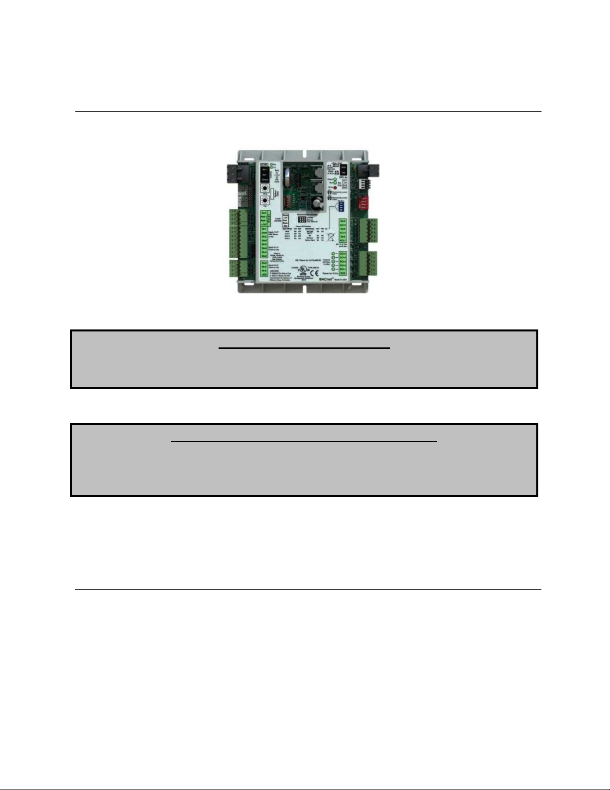
2. For BACnet MS/TP, N2, and Modbus, a shielded twisted pair network connection needs to be
connected to the RS-485 port in the upper left hand corner of the controller. Please refer to the
connector shown in Figure 1.
Fig. 1
3. For LonWorks, connect to the standard LonWorks communication port located on the LonWorks
daughter board(Figure 3), mounted on the daughter board bracket above the controller.
4
Page 5
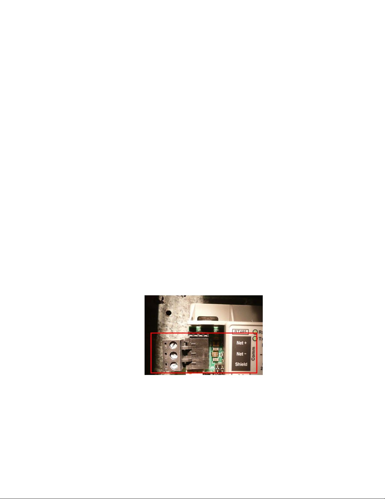
DDC PROTOCOL SELECTION
1.
The appropriate DDC controls protocol is factory set using dip switches on the DDC controller.
The four possible protocols are BACnet MS/TP, Metasys N2, Modbus, and LonWorks (LonTalk).
Confirm the dip switch setting prior to startup. A table showing the dip switch configurations
available is on the front label of the controller. Switches 1 and 2 control the BAUD rate. Switches
3 and 4 control the communication protocol. The factory BAUD rate 9600. Most LonWorks
systems use a different BAUD for connection (38.4K typical).
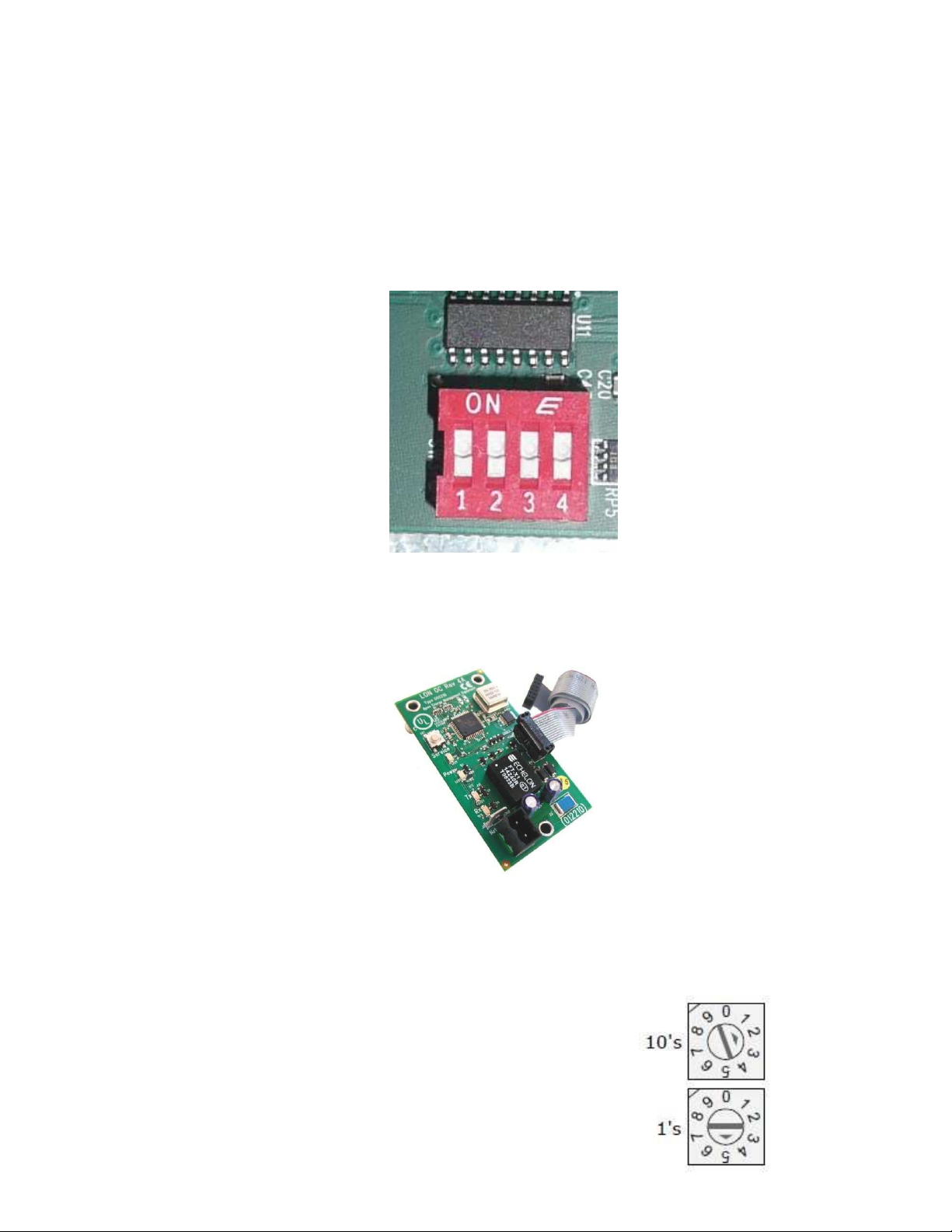
2.
NOTE: LonWorks protocol is only available with the optional LonWorks adapter card. If
ordered with this card, you will see a daughter circuit board mounted above the controller on a
daughter card bracket. The LonWorks card ( PN: LON-OC) is shown in Figure 3.
Fig. 2
Fig. 3
SETTING THE CONTROLLER ADDRESS
1. For each unit on the jobsite, there needs to be a specific address
set on the controller. If multiple units have the same address,
there will be communication problems in the field. The controller
has 2 rotary switches in the upper left side. The uppermost switch
is the “tens” digit and the lower switch is the “ones” digit. In the
example to the right the address is 25.
5
Page 6
2. Using the rotary switches, set the controllers address. The factory default is 03. The number
used is arbitrary, so long as it doesn’t conflict with other unit addresses on the network.
3. For N2 or Modbus connections, the address set on the rotary switches is the unit’s slave address.
4. If the unit was powered up for any reason during the rotary setting adjustment, a power cycle
needs to be performed to store the new address.
5. For LonWorks, the address is irrelevant, but must not be zero.
CONTROLS CONNECTION
1. The site specific method of communicating with the network should be powered on. This can be
a computer or alternatively a handheld or LCD DDC controls device such as the BACview.
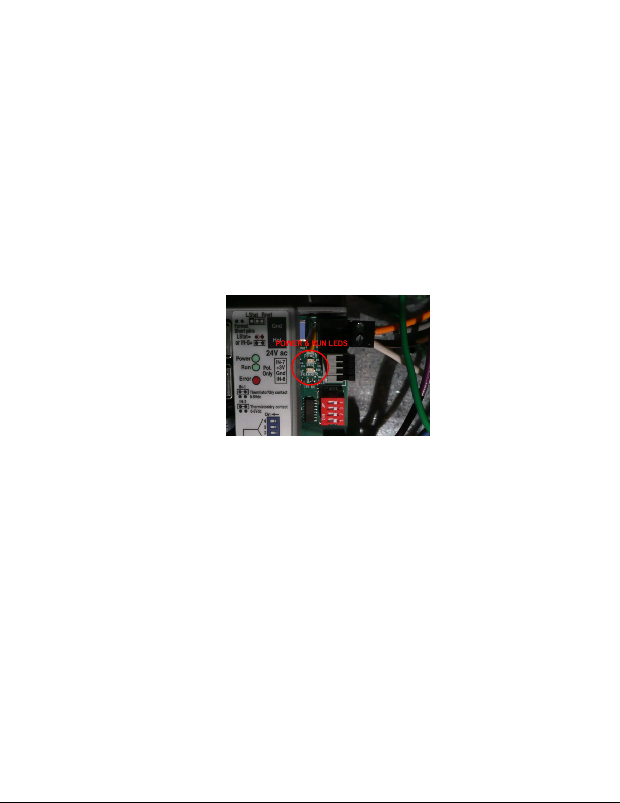
2. Next provide power to the heater/controls unit by turning on the breaker. Confirm that the DDC
controller has flashing lights in the upper right hand corner of the unit. A solid “power LED”
indicates proper power supply and a blinking “run LED” indicates that the unit is functioning and
running the program as expected. See Figure 4.
FIG. 4
3. Confirm that the unit is visible on the network, either through the computer interface or handheld
unit, if equipped.
6
Page 7

SOFTWARE SETUP & NETWORK VARIABLES
The DDC controller provides a fixed set of analog and binary variables for adjustment in the field. These
variables are listed below for each language. All variables are factory set (if applicable) to the values as
shown. The on-site DDC Controls Contractor should adjust values accordingly as required.
LIST OF ANALOG VARIABLES (AV):
AV: 1: Software Control Source. Use this variable to set the method of controlling the
occupied/unoccupied status of the unit.
Properties
- Editable using integer values only
- BACnet Reference: ctrl_source
- Modbus Register: 40001
- N2 Register: 1
- Lonworks ID: nviCtrlsrc
- Range: 0 to 4
- Description:
0 = digital input
1 = keypad control (service)
2 = building automation control using BV: 1
3 = BACnet Schedule control
4 = Override ON
AV: 2: Incoming Air Temperature Sensor. This variable provides the intake air temperature
sensor reading from the unit.
Properties
- Fixed readout. Non-editable
- BACnet Reference: iat_sensor_visible
- Modbus Register: 40027
- N2 Register: 14
- Lonworks ID: nvoIncomingAir
- Range of -25.0 to 225.0
- Units of degrees Fahrenheit (can be changed in software)
- Type II 10K Thermistor
AV: 3: Heating Supply Air Setpoint. Use this variable to set the heating supply air target setpoint
for the unit.
Properties
- Editable, precision to the tenth of a degree
- BACnet Reference: hsat_stpt
- Modbus Register: 40021
- N2 Register: 11
- Lonworks ID: nviHeatSupAirStp
- Units of degrees Fahrenheit (can be changed in software)
- Range: 40.0 to 140.0
- Default: 55.0
7
Page 8

AV: 4: Effective Heating Setpoint. This is the effective heating setpoint, after the inclusion of
internal logic to prevent rapid ramp-up/down of the value.
Properties
- Fixed readout. Non-editable
- BACnet Reference: eht_stpt
- Modbus Register: 40017
- N2 Register: 9
- Lonworks ID: nvoEffHeatStp
- Units of degrees Fahrenheit (can be changed in software)
- Has a maximum rise of 5.0 Degrees per 1 minute from AV:3
- Has a maximum fall of 5.0 Degrees per 1 minute from AV:3
AV: 5: Heating Intake Air Activation Setpoint. This variable is used to activate the call for heat. If
the Intake Air Temperature Sensor Value falls below this value, the call for heat output will be
activated.
Properties
- Editable, precision to the tenth of a degree.
- BACnet Reference: ht_iat_stpt
- Modbus Register: 40025
- N2 Register: 13
- Lonworks ID: nviHeatIntakeStp
- Units of degrees Fahrenheit (can be changed in software)
- Range: 40.0 to 90.0
- Default: 45.0
AV: 6: Cooling Intake Air Setpoint. This variable is used to activate the call for stage 1 cooling.
If the Intake Air Temperature Sensor Value rises above this value, the stage 1 cooling output will
be activated.
Properties
- Editable, precision to the tenth of a degree.
- BACnet Reference: cl_iat_stpt
- Modbus Register: 40003
- N2 Register: 2
- Lonworks ID: nviCoolIntakeStp
- Units of degrees Fahrenheit (can be changed in software)
- Range: 60.0 to 120.0
- Default: 85.0
AV: 7: Effective Cooling Setpoint. This is the effective cooling setpoint, after the inclusion of
internal logic to prevent rapid ramp-up/down of the value.
Properties
- Fixed readout. Non-editable
- BACnet Reference: ecl_stpt
- Modbus Register: 40013
- N2 Register: 7
- Lonworks ID: nvoEffCoolStp
- Units of degrees Fahrenheit (can be changed in software)
- Has a maximum rise of 5.0 Degrees per 5 minutes from AV:6
- Has a maximum fall of 3.0 Degrees per 5 minutes from AV:6
8
Page 9

AV: 8: Cooling Stage 2 Offset. This is the offset value from AV:6, which will activate the second
stage cooling. If the Intake Air Temperature rises above AV:6 + AV:8, 2nd stage cooling will
enable.
Properties
- Editable, precision to the tenth of a degree
- BACnet Reference: cl_s2_ofst
- Modbus Register: 40009
- N2 Register: 5
- Lonworks ID: nviCoolTwoOfst
- Units of degrees Fahrenheit (can be changed in software)
- Range: 1.0 to 30.0
AV: 9: Effective Discharge Air Temperature. This is the effective discharge air temperature, as
read from the unit’s internal discharge air sensor.
Properties
- Fixed readout. Non-editable
- BACnet Reference: edat
- Modbus Register: 40015
- N2 Register: 8
- Lonworks ID: nvoEffDisAirTemp
- Units of degrees Fahrenheit (can be changed in software)
- Range: -25.0 to 225.0
- Type II 10K Thermistor
AV: 10: Cooling Stage 1 Off Delay. This is the time, in minutes, of which the stage 1 cooling
must remain on after stage 2 cooling has been disabled. This prevents cycling between stage 1
and stage 2 cooling.
Properties
- Editable using integer values only
- BACnet Reference: s1_cl_dly
- Modbus Register: 40007
- N2 Register: 4
- Lonworks ID: nviCoolOneOffDly
- Units of minutes
- Range: 1 to 30
- Default: 5
AV: 11: Cooling Stage 2 On Delay. This is the time, in minutes, of which the stage 1 cooling must
be on before stage 2 cooling is allowable. This prevents abrupt cooling demand if the network
were to have a large fluctuation of intake air temperature values.
Properties
- Editable using integer values only
- BACnet Reference: s2_cl_dly
- Modbus Register: 400011
- N2 Register: 6
- Lonworks ID: nviCoolTwoOnDly
- Units of minutes
- Range: 1 to 30
- Default: 5
9
Page 10

10
AV: 12: Heating Valve Output. This is the output, in percentage, of the PID loop which feeds the
heating valve. A value of 0% is low fire, and a value of 100% is high fire.
Properties
- Fixed readout. Non-editable. This value is determined by comparison of
AV: 4 to AV: 9 using the PID loop
- BACnet Reference: htg_vlv_out
- Modbus Register: 40023
- N2 Register: 12
- Lonworks ID: nvoHeatVlvOut
- Units of percentage
- Range: 0.0 to 100.0%
AV: 13: VFD Speed Input. This is the network input, in volts (V), of which will be used by the
controller to send out a 0 to 10 V signal to an internal VFD. For externally network controlled
VFDs, this AV is not to be used.
Properties
- Editable, precision to the tenth decimal place
- BACnet Reference: vfd_spd_in
- Modbus Register: 40041
- N2 Register: 21
- Lonworks ID: nviVFDSpdInput
- Units of Volts
- Range: 0.0 to 10.0
AV: 14: VFD Speed Output. This is the output, in volts (V), which is being sent to the VFD by the
controller. This is for internally controlled VFDs only. This AV is simply a confirmation of
receiving the input from AV:13.
Properties
- Fixed readout. Non-editable.
- BACnet Reference: vfd_spd_out
- Modbus Register: 40043
- N2 Register: 22
- Lonworks ID: nvoVFDSpdOut
- Units of Volts
- Range: 0.0 to 10.0
AV: 15: Modulating Damper Input. This is the network input, in volts (V), of which will be used by
the controller to send out a 0.0 to 10.0 V signal to the modulating damper.
Properties
- Editable, precision to the tenth decimal place
- BACnet Reference: mod_dmp_in
- Modbus Register: 40029
- N2 Register: 15
- Lonworks ID: nviModDmpInput
- Units of Volts
- Range: 0.0 to 10.0
Page 11

11
AV: 16: Modulating Damper Output. This is the output, in volts (V), which is being sent to the
modulating damper from the controller. This AV is simply a confirmation of receiving the input
from AV:15.
Properties
- Fixed readout. Non-editable.
- BACnet Reference: mod_dmp_out
- Modbus Register: 40031
- N2 Register: 16
- Lonworks ID: nvoModDmpOut
- Units of Volts
- Range: 0.0 to 10.0
AV: 17: Heating Room Override Supply Air Setpoint. This variable is used to control the supply
air temp when the Room Override (BV:16) is on. This occurs when BV:17 is set to “On” or
“Space” and the space temperature (AV:20) falls below the space heating setpoint (AV:21 minus
AV:22). Used as a space heating function.
Properties
- Editable, precision to the tenth of a degree.
- BACnet Reference: rodt_heat_stpt
- Modbus Register: 40035
- N2 Register: 18
- Lonworks ID: nviRoomOvSAT
- Units of degrees Fahrenheit (can be changed in software)
- Range: 80.0 to 140.0
- Default: 120.0
AV: 18: Cooling Intake Air Low Temp Lockout. This variable is used to prevent cooling if the
intake air temperature is too low. If the Intake Air Temperature Sensor Value falls below this
value, the call for cooling will not be permitted.
Properties
- Editable, precision to the tenth of a degree.
- BACnet Reference: cool_intake_lockout
- Modbus Register: 40005
- N2 Register: 3
- Lonworks ID: nviCoolILOLowT
- Units of degrees Fahrenheit (can be changed in software)
- Range: 60.0 to 130.0
- Default: 65.0
AV: 19: Heating Intake Air High Temp Lockout. This variable is used to prevent heating if the
intake air temperature is too high. If the Intake Air Temperature Sensor Value rises above this
value, the call for heating will not be permitted.
Properties
- Editable, precision to the tenth of a degree.
- BACnet Reference: heat_intake_lockout
- Modbus Register: 40019
- N2 Register: 10
- Lonworks ID: nviHeatILOHighT
- Units of degrees Fahrenheit (can be changed in software)
- Range: 35.0 to 130.0
- Default: 65.0
Page 12

12
AV: 20: Space (Room) Air Temperature Sensor. This variable provides the room air temperature
sensor reading from the field installed sensor.
Properties
- Fixed readout. Non-editable
- BACnet Reference: rat_sensor_visible
- Modbus Register: 40043
- N2 Register: 22
- Lonworks ID: nvoRoomTSensor
- Range of -25.0 to 225.0
- Units of degrees Fahrenheit (can be changed in software)
- Type II 10K Thermistor
AV: 21: Heating Room Temperature Setpoint. This variable is used to activate the space heating
function. This occurs when BV:17 is set to “On” or “Space” and the space temperature (AV:20)
falls below the space heating setpoint (AV:21 minus AV:22). Used as a space heating function.
Properties
- Editable, precision to the tenth of a degree.
- BACnet Reference: rt_heat_stpt
- Modbus Register: 40037
- N2 Register: 19
- Lonworks ID: nviRoomTStpt
- Units of degrees Fahrenheit (can be changed in software)
- Range: 50.0 to 90.0
- Default: 70.0
AV: 22: Heating Room Temperature Setpoint Differential. This variable is used to adjust the
space heating setpoint differential to keep space heating supply temp from bouncing.
Properties
- Editable, precision to the tenth of a degree.
- BACnet Reference: rt_heat_stpt_diff
- Modbus Register: 40039
- N2 Register: 20
- Lonworks ID: nviRoomTDiff
- Units of degrees Fahrenheit (can be changed in software)
- Range: 1.0 to 10.0
- Default: 2.0
Page 13

13
LIST OF BINARY VARIABLES (BV):
BV: 1: BV Unit Enable (BAS). This is the Unoccupied/Occupied switch used for BAS control of
unit run condition. NOTE: AV:1 must be set to 2 for BV:1 to function.
Properties
- On/Off Switch.
- BACnet Reference: enable_bas
- Modbus Register: 3
- N2 Register: 3
- Lonworks ID: nviEnableBMS
BV: 2: Occupancy Status. This is the Unoccupied/Occupied confirmation BV, used to confirm the
occupied/unoccupied state of the unit. Can be activated by numerous sources, as outlined in
section AV:1.
Properties
- Fixed readout. Status only.
- BACnet Reference: occ_status
- Modbus Register: 10005
- N2 Register: 5
- Lonworks ID: nvoOccStatus
BV: 3: Supply Fan Command. This is the command controlling the Supply Fan Output. Used to
confirm if the unit is calling for Supply Fan Activation.
Properties
- Fixed readout. Status only.
- BACnet Reference: sf_cmd
- Modbus Register: 10011
- N2 Register: 11
- Lonworks ID: nvoSupFanCmd
BV: 4: Supply Fan Status. This is the status of the Supply Fan. This will only show an On State
when sufficient airflow is induced to activate the internal airflow proving switches, or when an
internal network airflow proving input has been activated.
Properties
- Fixed readout. Status only.
- Network Reference: sf_status
- Modbus Register: 10012
- N2 Register: 12
- Lonworks ID: nvoSupFanStatus
BV: 5: Airflow Proving Status. This is the status of the internal airflow proving switches. This will
only show an On State when unit airflow is between the high and low limits, which are preset and
non-adjustable.
Properties
- Fixed readout. Status only.
- Network Reference: af_sts
- Modbus Register: 10002
- N2 Register: 2
- Lonworks ID: nvoAirFlowProv
Page 14

14
BV: 6: Outside Air Damper Command. This is the command to control the on/off state of the
outside air damper. Used to confirm if the unit is calling for outside air damper to be open.
Properties
- Fixed readout. Status only.
- Network Reference: oad_cmd
- Modbus Register: 10006
- N2 Register: 6
- Lonworks ID: nvoDampCmd
BV: 7: Outside Air Damper Status. This is the status of the Outside Air Damper. This will only
show an On State when the damper end limit switch has been activated.
Properties
- Fixed readout. Status only.
- Network Reference: oad_sts
- Modbus Register: 10007
- N2 Register: 7
- Lonworks ID: nvoDampStatus
BV: 8: 1st Stage Cooling On. This is the request for stage 1 cooling directly from the network.
This command can be activated whenever stage 1 cooling should be run. Cooling must be
allowed by external logic, and other safeties must be satisfied before the compressor will activate.
Properties
- On/Off Switch.
- Network Reference: s1_clg_on
- Modbus Register: 1
- N2 Register: 1
- Lonworks ID: nviCoolOneOn
- Requires BV:4 to be On
- Requires Heating to be off
- Requires AV: 2 to be > AV:6 and AV:18 Degrees Fahrenheit
- Does not override minimum on/off cycle time logic
BV: 9: 1st Stage Cooling Command. This is the command used to activate the stage 1 cooling
output from the controller.
Properties
- Fixed readout. Status only.
- Network Reference: s1_clg_cmd
- Modbus Register: 10029
- N2 Register: 29
- Lonworks ID: nvoCoolOneCmd
- Activates from either BV: 8 or when the call for cooling logic is satisfied using AV: 2 and
AV: 7
BV: 10: 2nd Stage Cooling On. This is the request for stage 2 cooling directly from the network.
This command can be activated whenever stage 2 cooling should be run. Cooling must be
allowed by external logic, and other safeties must be satisfied before the compressor will activate.
Properties
- On/Off Switch.
- Network Reference: s2_clg_on
- Modbus Register: 2
- N2 Register: 2
- Lonworks ID: nviCoolTwoOn
- Requires BV: 9 to be activated for a period of time longer than AV: 11
- Does not override minimum on/off cycle time logic
Page 15

15
BV: 11: 2nd Stage Cooling Command. This is the command used to activate the stage 2 cooling
output from the controller.
Properties
- Fixed readout. Status only.
- Network Reference: s2_clg_cmd
- Modbus Register: 10001
- N2 Register: 1
- Lonworks ID: nvoCoolTwoCmd
- Activates from either BV: 10 or when the call for second stage cooling logic is satisfied
using AV: 2, AV: 7, and AV: 8
BV: 12: Heat On Command. This is the command used to activate the call for heat relay.
Properties
- Fixed readout. Status only.
- Network Reference: ht_on_cmd
- Modbus Register: 10004
- N2 Register: 4
- Lonworks ID: nvoHeatOnCmd
- Activates when a call for heat is determined from comparison of AV: 2 to AV: 5
BV: 13: Clogged Filter Status. This is the status of the clogged filter input to the controller. A
value displayed here is only relevant if the clogged filter option was ordered with the unit.
Properties
- Fixed readout. Status only.
- Network Reference: fltr_sts
- Modbus Register: 10003
- N2 Register: 3
- Lonworks ID: nvoClogFltrSts
- Activates when the clogged filter input is On. An On state is the normal run condition.
An Off state indicates clogged filter. A clogged filter alarm will sound (see alarm section).
BV: 14: Smoke Detector Status. This is the status of the smoke detector input to the controller.
A value displayed here is only relevant if the smoke detector option was ordered with the unit.
Properties
- Fixed readout. Status only.
- Network Reference: smk_sts
- Modbus Register: 10009
- N2 Register: 9
- Lonworks ID: nvoSmokDtctSts
- Activates when the smoke detector input is On. An On state is the alarm state
condition. A Smoke alarm will sound and shut down the unit (see alarm section).
BV: 15: Emergency Alarm. This is the network input for an emergency alarm. If the network
value of this input is changed to On, the unit will shut down.
Properties
- On/Off Switch
- Network Reference: emerg_alm_in
- Modbus Register: 4
- N2 Register: 4
- Lonworks ID: nviEmerAlarmOn
Page 16

16
BV: 16: Room Override Status. This is the status of the room override space heating function. .
Room Override will be On if the unit is operating in space heating mode.
Properties
- Fixed readout. Status only.
- Network Reference: room_override
- Modbus Register: 10008
- N2 Register: 8
- Lonworks ID: nvoRoomOver
- This occurs when BV:17 is set to “On” or “Space” and the space temperature (AV:20)
falls below the space heating setpoint (AV:21 minus AV:22). Used as a space heating
function.
BV: 17: Heating Temperature Control. This can either be set to “OFF” (Discharge heating
temperature control) or “ON” (Space heating temperature control)
Properties
- On/Off Switch
- Network Reference: eat_control
- Modbus Register: 7
- N2 Register: 7
- Lonworks ID: nviHeatControl
NETWORK ALARM VARIABLES
The DDC controller provides a set of alarms for various status notifications. These alarms are listed
below. The on-site DDC Controls Contractor should link the alarm values accordingly as required to
operate the facility in accordance with specifications.
BV: 31 AF_FAIL: Airflow Failure.
- Network Reference: af_fail
- Modbus Register: 10013
- N2 Register: 13
- Lonworks ID: nvoAfFailAlm
- Activates if BV: 2, occupancy status, is in occupied mode for longer than 5:00 minutes, and
airflow has not yet been established.
BV: 32 CLG_FLTR: Filter Change Required.
- Network Reference: clg_fltr
- Modbus Register: 10014
- N2 Register: 14
- Lonworks ID: nvoFltClgAlm
- Activates if BV:13, the Clogged Filter Status, is Off for 10:00 minutes, and BV: 2 indicates
that the unit is in the occupied state.
BV: 33 CLG_RNTM: Cooling Runtime Expired.
- Network Reference: clg_rntm
- Modbus Register: 10015
- N2 Register: 15
- Lonworks ID: nvoFltClgRntmAlm
- Activates if BV: 9 or BV:11 have been in the On state for 10000 hours.
BV: 34 CSAT_HI: High Cooling Supply Air Temperature.
- Network Reference: csat_hi
- Modbus Register: 10016
- N2 Register: 16
- Lonworks ID: nvoCoolSATHiAlm
Page 17

17
- Activates if AV: 9, the Discharge Air Temperature, is greater than AV: 7, the cooling setpoint,
plus 5.0 degrees, for 5 minutes. Cooling must be on for this alarm to occur.
BV: 35 FREEZE: Freezestat.
- Network Reference: freeze
- Modbus Register: 10017
- N2 Register: 17
- Lonworks ID: nvoFreezeAlm
- Activates if AV: 9, the Discharge Air Temperature, is less than 35 Degrees, and BV: 2
indicates that the unit is in the occupied state. Will not activate unless the above conditions
are true for 10:00 minutes of run time.
- This Alarm is a shutdown alarm.
BV: 36 HSAT_LO: Low Heating Supply Air Temperature.
- Network Reference: hsat_lo
- Modbus Register: 10018
- N2 Register: 18
- Lonworks ID: nvoHeatSATLoAlm
- Activates if AV: 9, the Discharge Air Temperature, is less than AV: 4, the Heating Setpoint,
minus 5.0 Degrees. Heating must be on for a minimum of 5:00 minutes for alarm to activate.
Unit must be in this state for 10:00 minutes before alarm will activate.
BV: 37 HT_FAIL: Heating Failure.
- Network Reference: ht_fail
- Modbus Register: 10019
- N2 Register: 19
- Lonworks ID: nvoHeatFailAlm
- Activates if AV: 9, the Discharge Air Temperature, is less than AV: 2, the Intake Air
Temperature, plus 5.0 Degrees. Heating must be on for alarm to activate. Unit must be in
this state for 3:00 minutes before alarm will activate.
BV: 38 KEY_OUT_LCK: Keypad Output Locked.
- Network Reference: key_out_lck
- Modbus Register: 10020
- N2 Register: 20
- Lonworks ID: nvoKeyPadAlm
- Activates if any of the keypad overrides are left in the locked on status. This alarm prevents
a service technician from leaving the unit in a locked out state.
BV: 39 OAD_FAIL: Outside Air Damper Failure.
- Network Reference: oad_fail
- Modbus Register: 10021
- N2 Register: 21
- Lonworks ID: nvoOadFailAlm
- Activates if BV: 6, the Outside Air Damper Command, is Off, however BV: 7, the Outside Air
Damper Status, is On. There is a 90 second feedback delay.
BV: 40 OAD_HAND: Outside Air Damper In Hand.
- Network Reference: oad_hand
- Modbus Register: 10022
- N2 Register: 22
- Lonworks ID: nvoOadHandAlm
- Activates if BV: 6, the Outside Air Damper Command, is On, however BV: 7, the Outside Air
Damper Status, is Off. There is a 90 second feedback delay.
BV: 41 OAD_RNTM: Outside Air Damper Runtime Expired.
Page 18

18
- Network Reference: oad_rntm
- Modbus Register: 10023
- N2 Register: 23
- Lonworks ID: nvoOadRntmAlm
- Activates if BV: 7 has been in the On state for 10000 hours.
BV: 42 SAT_HI: High Supply Air Temperature.
- Network Reference: sat_hi
- Modbus Register: 10024
- N2 Register: 24
- Lonworks ID: nvoSATHiAlm
- Activates if AV: 9, the Discharge Air Temperature, is greater than 160 Degrees for 10:00
minutes, and the unit has proper airflow.
BV: 43 SAT_LO: Low Supply Air Temperature.
- Network Reference: sat_lo
- Modbus Register: 10025
- N2 Register: 25
- Lonworks ID: nvoSATLoAlm
- Activates if AV: 9, the Discharge Air Temperature, is less than 35 Degrees for 10:00 minutes,
and the unit has proper airflow.
BV: 44 SF_FAIL: Supply Fan Failure.
- Network Reference: sf_fail
- Modbus Register: 10026
- N2 Register: 26
- Lonworks ID: nvoSfFailAlm
- Activates if BV: 3, the Supply Fan Command, is Off, however BV: 4, the Supply Fan Status, is
On. There is a 30 second feedback delay.
BV: 45 SF_HAND: Supply Fan In Hand.
- Network Reference: sf_hand
- Modbus Register: 10027
- N2 Register: 27
- Lonworks ID: nvoSFHandAlm
- Activates if BV: 3, the Supply Fan Command, is On, however BV: 4, the Supply Fan Status, is
Off. There is a 30 second feedback delay.
BV: 46 SF_RNTM: Supply Fan Runtime Expired.
- Network Reference: sf_rntm
- Modbus Register: 10028
- N2 Register: 28
- Lonworks ID: nvoSfRntmAlm
- Activates if BV: 4 has been in the On state for 10000 hours.
BV: 47 SMOKE: Smoke Detector Alarm.
- Network Reference: smoke
- Modbus Register: 10029
- N2 Register: 29
- Lonworks ID: nvoSmokeAlm
- Activates if BV: 14, the Smoke Detector Status, is in the On state. There is no delay.
- This alarm is a shutdown alarm.
Page 19

19
LOGIC MODIFICATION NOTES
AV:1
AV:2
AV:3
AV:4
AV:5
AV:6
AV:7
AV:8
AV:9
AV:10
AV:11
AV:12
AV:13
AV:14
AV:15
AV:16
AV:17
AV:18
AV:19
AV:20
AV:21
AV:22
BV:1
BV:2
BV:3
BV:4
BV:5
BV:6
BV:7
BV:8
BV:9
BV:10
BV:11
BV:12
BV:13
BV:14
BV:15
BV:16
BV:17
Page 20

20
Start-Up and Maintenance Documentation
Job Information
Job Name Service Company
Address Address
City City
State State
Zip Zip
Phone Number Phone Number
Fax Number Fax Number
Contact Contact
Purchase Date Start-Up Date
Date Service Performed
NOTES:
Factory Service Department
Phone: 1-866-784-6900
Fax: 1-919-554-9374
 Loading...