

Page 1
FOR YOUR SAFETY
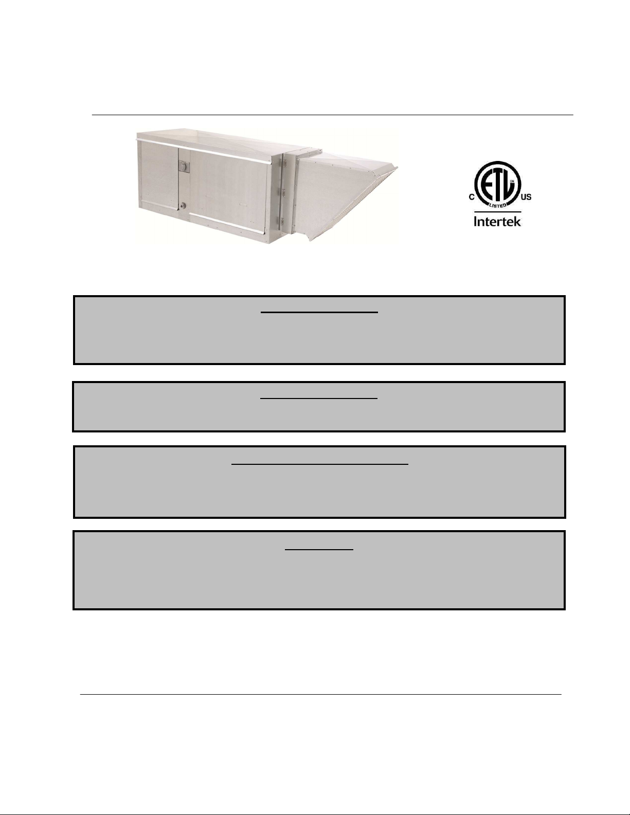
Compact
Direct Fired
Heater
Installation, Operation, and Maintenance Manual
Save these instructions
RECEIVING AND INSPECTION
WARNING!!
FOR YOUR SAFETY
If you smell gas:
1. Open windows.
2. Don’t touch electrical switches.
3. Extinguish any open flames.
The use and storage of gasoline or other flammable vapors and liquids in open containers in the
vicinity of this appliance is hazardous.
Upon receiving unit, check for any interior and exterior damage, and if found, report it
immediately to the carrier. Also check that all accessory items are accounted for and are
damage free. Turn the blower wheel by hand to verify free rotation and check the damper (if
supplied) for free operation.
Improper installation, adjustment, alteration, service or maintenance can cause property
damage, injury or death. Read the installation, operating and maintenance instructions
thoroughly before installing or servicing this equipment. ALWAYS disconnect power and gas
prior to working on heater.
. This document is the property of the owner of this equipment and is
required for future maintenance. Leave this document with the owner when installation or service
is complete.
A0011029
April 2013 Rev. 9
Page 2

Page 3

TABLE OF CONTENTS
WARRANTY ...................................................................................................................................................................................... 4
INSTALLATION ................................................................................................................................................................................. 5
Mechanical ................................................................................................................................................................................... 5
Site Preparation ...................................................................................................................................................................... 5
Assembly ................................................................................................................................................................................ 5
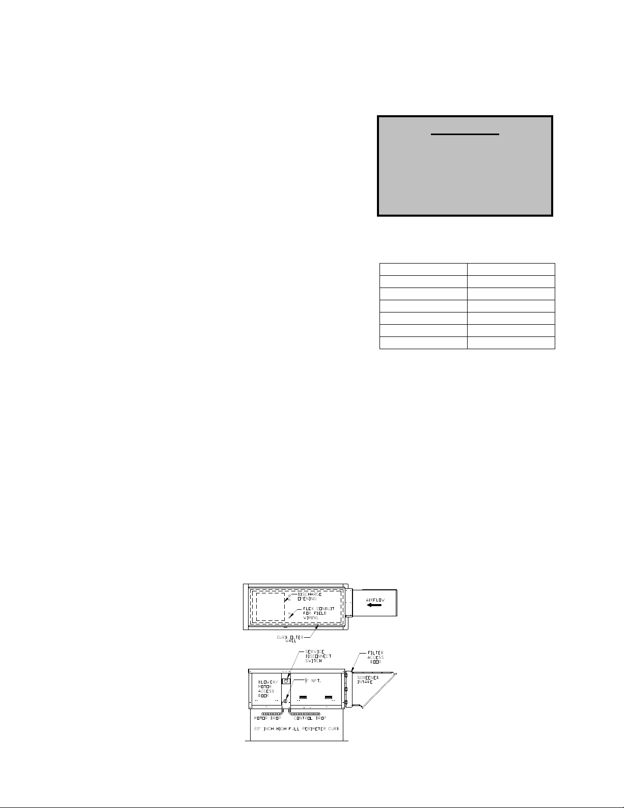
Curb and Ductwork ................................................................................................................................................................. 6
Roof Mount Installation............................................................................................................................................................ 6
Installation with Exhaust Fan ................................................................................................................................................... 7
Indoor (INLINE) Installation ..................................................................................................................................................... 7
Gas .............................................................................................................................................................................................. 8
Gas Connection Sizes ............................................................................................................................................................. 8
Gas Pressure Table ................................................................................................................................................................ 8
Gas Connection Diagram ........................................................................................................................................................ 8
Electrical ...................................................................................................................................................................................... 9
Copper Wire Ampacity ............................................................................................................................................................ 9
PSC (Permanent Split Capacitor) Motor Speed Control ......................................................................................................... 10
ECM (Electronically Controlled Motor) Speed Control ........................................................................................................... 10
Motorized Intake Damper ...................................................................................................................................................... 11
Electric Cabinet Heater ......................................................................................................................................................... 11
Remote Control Panel ........................................................................................................................................................... 11
Fan to Building Wiring Connection ........................................................................................................................................ 12
OPERATION ................................................................................................................................................................................... 12
Start Up ...................................................................................................................................................................................... 12
Special Tools Required ......................................................................................................................................................... 12
Start Up Procedure ............................................................................................................................................................... 12
Pilot Adjustment .................................................................................................................................................................... 13
Pilot Assembly ...................................................................................................................................................................... 13
Main Burner Adjustment ........................................................................................................................................................ 14
Heater Start Up Summary ..................................................................................................................................................... 15
Final Start Up Procedure ....................................................................................................................................................... 16
Pulley Adjustment ................................................................................................................................................................. 16
Pulley Alignment ................................................................................................................................................................... 16
Proper Belt Tension .............................................................................................................................................................. 16
Pulley Setscrew Torque ........................................................................................................................................................ 16
Pulley Combination Chart ...................................................................................................................................................... 17
Sequence of Operation ............................................................................................................................................................... 17
Flame Safety Control ............................................................................................................................................................ 17
Air Flow Switch ..................................................................................................................................................................... 18
Modulating Gas System ........................................................................................................................................................ 18
High Temperature Limit ......................................................................................................................................................... 19
Operation Summary .............................................................................................................................................................. 19
Optional Remote Panel Circuit .............................................................................................................................................. 20
Components ............................................................................................................................................................................... 21
Remote Panel Option ............................................................................................................................................................ 22
Troubleshooting.......................................................................................................................................................................... 23
Airflow Troubleshooting Chart ............................................................................................................................................... 23
Burner Troubleshooting Chart ............................................................................................................................................... 24
Remote Panel Troubleshooting Chart ................................................................................................................................... 25
Troubleshooting Flowcharts .................................................................................................................................................. 26
MAINTENANCE .............................................................................................................................................................................. 27
General Maintenance ................................................................................................................................................................. 27
2 weeks after startup .................................................................................................................................................................. 28
Every 3 months .......................................................................................................................................................................... 28
Filter Quantity Chart .............................................................................................................................................................. 28
Yearly ......................................................................................................................................................................................... 28
Burner Orifice Drill Size ........................................................................................................................................................ 28
Start-Up and Maintenance Documentation ................................................................................................................................. 29
Job Information ..................................................................................................................................................................... 29
Heater Information ................................................................................................................................................................ 29
Maintenance Record ............................................................................................................................................................. 29
Factory Service Department .................................................................................................................................................. 29
3
Page 4

WARRANTY
This equipment is warranted to be free from defects in materials and workmanship, under normal use and
service, for a period of 12 months from date of shipment. This warranty shall not apply if:
1. The equipment is not installed by a qualified installer per the MANUFACTURER’S installation
instructions shipped with the product,
2. The equipment is not installed in accordance with federal, state and local codes and regulations,
3. The equipment is misused or neglected,
4. The equipment is not operated within its published capacity,
5. The invoice is not paid within the terms of the sales agreement.
The MANUFACTURER shall not be liable for incidental and consequential losses and damages
potentially attributable to malfunctioning equipment. Should any part of the equipment prove to be
defective in material or workmanship within the 12-month warranty period, upon examination by the
MANUFACTURER, such part will be repaired or replaced by MANUFACTURER at no charge. The
BUYER shall pay all labor costs incurred in connection with such repair or replacement. Equipment shall
not be returned without MANUFACTURER’S prior authorization and all returned equipment shall be
shipped by the BUYER, freight prepaid to a destination determined by the MANUFACTURER.
4
Page 5

INSTALLATION
CLEARANCES
It is imperative that this unit is installed and operated with the designed airflow, gas, and electrical supply
in accordance with this manual. If there are any questions about any items, please call the service
department at 1-866-784-6900 for warranty and technical support issues.
Mechanical
WARNING: DO NOT RAISE VENTILATOR BY THE INTAKE HOOD, BLOWER OR
MOTOR SHAFT, OR BEARINGS, THE USE OF A SLING IS ADVISED.
Site Preparation
1. Provide clearance around installation site to safely rig and
lift equipment into its final position. Supports must
adequately support equipment. Refer to manufacturer’s
estimated weights.
2. Consider general service and installation space when
locating unit.
3. Locate unit close to the space it will serve to reduce long,
twisted duct runs.
4. Do not allow air intake to face prevailing winds. Support
unit above ground or at roof level high enough to prevent
precipitation from being drawn into its inlet. The inlet must
also be located at least 10 feet away from any exhaust
vents. The heater inlet shall be located in accordance with the applicable building code
provisions for ventilation air. All air to the heater must be ducted from the outdoors. Recirculation
of room air is not permitted. If in doubt regarding the application, consult the manufacturer.
The top, back, and front
surfaces of this heater may not
be installed less than 6” from
combustible materials. The
heater base may be installed
on combustible surfaces.
Allow 24” minimum service
clearance on both sides of this
heater.
Assembly
Intakes and curbs are shipped unassembled. Upon unit arrival, follow the following procedure to
assemble the intake to the heater:
1. Apply silicone or weather-proof gasket on the back side of the flanges of the intake hood or
filtered intake.
2. Screw the flanges of the intake hood or filtered intake to the unit with the supplied sheet metal
screws. Cover screw heads with silicone to prevent water leaks.
5
Page 6
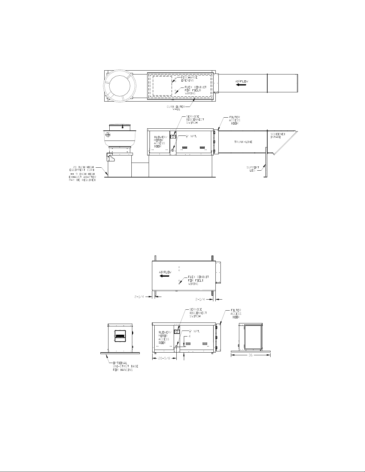
Curb and Ductwork
This fan was specified for a specific CFM and static pressure. The ductwork attached to this unit will
significantly affect the airflow performance. Flexible ductwork and square elbows should not be used.
Also, transitions and turns in ductwork near the fan outlet will cause system effect and will drastically
increase the static pressure and reduce airflow. The minimum fan outlet duct size is 12 inches x 12
inches with a recommended minimum straight duct length of 36 inches. Follow SMACNA guides and
recommendations for the remaining duct run.
Fans designed for rooftop installation should be installed on a prefabricated or factory built roof curb.
Follow curb manufacturer’s instructions for proper curb installation. The unit should be installed on a curb
and/or rail elevated not less than 20” above any surface. Be sure duct connection and fan outlet are
properly aligned and sealed. Secure fan to curb through vertical portion of the ventilator base assembly
flange using a minimum of eight (8) lug screws, anchor bolts, or other suitable fasteners (not furnished).
Shims may be required depending upon curb installation and roofing material. Check all fasteners for
tightness. The diagrams below show different mechanical installation configurations.
Adequate building relief shall be provided so as to not over pressurize the building when the heating
system is operating at its rated capacity. This can be accomplished by taking into account, through
standard engineering methods, the structure’s designed infiltration rate; by providing properly sized relief
openings; or by interlocking a powered exhaust system; or by a combination of these methods.
Heaters installed with intake ductwork must be purged to replace at least four air changes of the volume
of the intake duct.
If the failure or malfunction of this heater creates a hazard to other fuel burning equipment in the building
(e.g. when the heater is providing make up air to a boiler room), the unit is to be interlocked to open inlet
air dampers or other such devices.
Units being installed in airplane hangars should be installed in accordance with the Standard for Aircraft
Hangars, ANSI/NFPA 409. Units being installed in public garages should be installed in accordance
with the Standard for Parking Structures, ANSI/NFPA 88A, or the Standard for Repair Garages,
ANSI/NFPA 88B, and with CAN/CGA B149 Installation Codes.
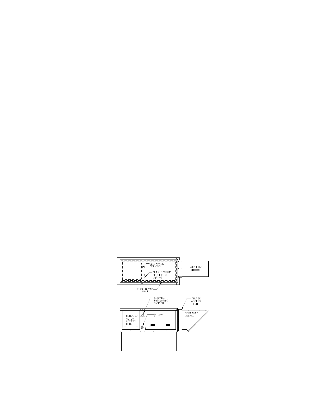
Roof Mount Installation
6
Page 7
Installation with Exhaust Fan
Indoor (INLINE) Installation
7
Page 8
Gas
NOTICE
Installation of gas piping must conform with local building codes, or in the absence of local codes, with the
National Fuel Gas Code, ANSI Z223.1 (NFPA 54) – latest edition. In Canada, installation must be in
accordance with CAN/CGA-B149.1 for natural gas units and CAN/CGA-B149.2 for propane units.
WARNING: INLET GAS PRESSURE MUST NOT EXCEED PRESSURE INDICATED
ON NAMEPLATE. SEE UNIT NAMEPLATE FOR PROPER GAS SUPPLY
PRESSURE AND GAS TYPE.
1. Always disconnect power before working on or near a heater. Lock and tag the disconnect
switch or breaker to prevent accidental power up.
2. Piping to the unit should conform with local and national requirements for type and volume of gas
handled, and pressure drop allowed in the line. Refer to the Gas Engineer’s Handbook for gas
line capacities.
3. The incoming pipe near the heater should be sized to
match the connection on the outside of the unit. Unit inlet
sizes are shown in the table to the right. Avoid multiple
taps in the gas supply so the unit has a steady supply of
gas at all times.
4. Install a ground joint union with brass seat and a manual
shut-off valve external to the unit casing, as shown below,
adjacent to the unit for emergency shut-off and easy servicing of controls.
5. Provide a sediment trap, as shown below, before each unit and where low spots in the pipe line
cannot be avoided.
6. Blow out the gas line to remove debris
before making connections. Purge line to
remove air before attempting to start unit.
Purging of air from gas lines should be
performed as described in ANSI Z223.1latest edition “National Fuel Gas Code”, or
in Canada in CAN/CGA-B149.
7. All field gas piping must be pressure/leak tested prior to unit operation. Use a non-corrosive
bubble forming solution or equivalent for leak testing. The heater and its individual shut-off valve
must be disconnected from the gas supply piping system during any pressure testing of that
system at test pressures in excess of ½ psi. The heater must be isolated from the gas supply
piping system by closing its individual manual shutoff valve during any pressure testing of the gas
supply piping system at test pressures equal to or less than ½ psi.
8. This unit requires a constant 5 in. w.c. minimum
natural gas supply, when the unit is operating at
maximum gas flow. If the gas supply exceeds 14
in. w.c. it will damage the internal valve
components, and if it is below 5 in. w.c., the heater
may not perform to specifications.
Gas Pressure Type Gas Pressure
Natural 5 in. w.c. – 14 in. w.c.
LP 5 in. w.c. – 14 in. w.c.
Gas Connection Sizes
Unit Size Gas Pipe Size
(NPT)
76 1/2”
Gas Pressure Table
Gas Connection Diagram
Refer to the heater rating
plate for determining the
minimum gas supply pressure
for obtaining the maximum
gas capacity for which this
heater is specified.
8
Page 9
Electrical
WARNING!!
Before connecting power to the heater, read and understand this entire section of this document. As-built
wiring diagrams are furnished with each fan by the factory, and
are attached to the door of the unit.
Electrical wiring and connections should be done in accordance
with local ordnances and the National Electric Code,
ANSI/NFPA70. Be sure the voltage and phase of the power
supply and the wire amperage capacity is in accordance with the
motor nameplate. For additional safety information refer to
AMCA publication 410-96, Recommended Safety Practices for
Users and Installers of Industrial and Commercial Fans.
Disconnect power before
installing or servicing fan. High
voltage electrical input is
needed for this equipment. This
work should be performed by a
qualified electrician.
1. Always disconnect power before working on or near a
heater. Lock and tag the disconnect switch or breaker to
prevent accidental power up.
2. An electrical drop containing the motor power wiring is
shipped with every fan. The electrical drop should be
brought through one of the conduit openings located in
the base of the unit, run through the curb, and connected
to a junction box inside the building.
3. A dedicated branch circuit should supply the motor circuit
with short circuit protection according to the National
Electric Code. This dedicated branch should be run to the junction box mentioned above and
connected as shown in a following illustration labeled “Fan to Building Wiring Connection”.
4. Make certain that the power source is compatible with the requirements of your equipment. The
heater nameplate identifies the proper phase and voltage of the motor.
5. Units shipped with an optional remote panel have two electrical circuit drops. It is important to
run the motor wires in a separate conduit from the remote control wiring. The DC wires from the
unit temperature controller, located in the control drop, should either be shielded cable or be run
in a separate conduit.
6. Before connecting heater to the building power source, verify power line wiring is de-energized.
7. Secure the power cables to prevent contact with sharp objects.
8. Do not kink power cable and never allow the cable to come in contact with oil, grease, hot
surfaces or chemicals.
9. Before powering up the heater, check fan wheel for free rotation and make sure that the interior of
the heater is free of loose debris or shipping materials.
10. If any of the original wire supplied with the heater must be replaced, it must be replaced with type
TW wire or equivalent.
Copper Wire Ampacity
Wire Size AWG Maximum Amps
14 20
12 25
10 30
8 40
6 55
4 70
9
Page 10
10
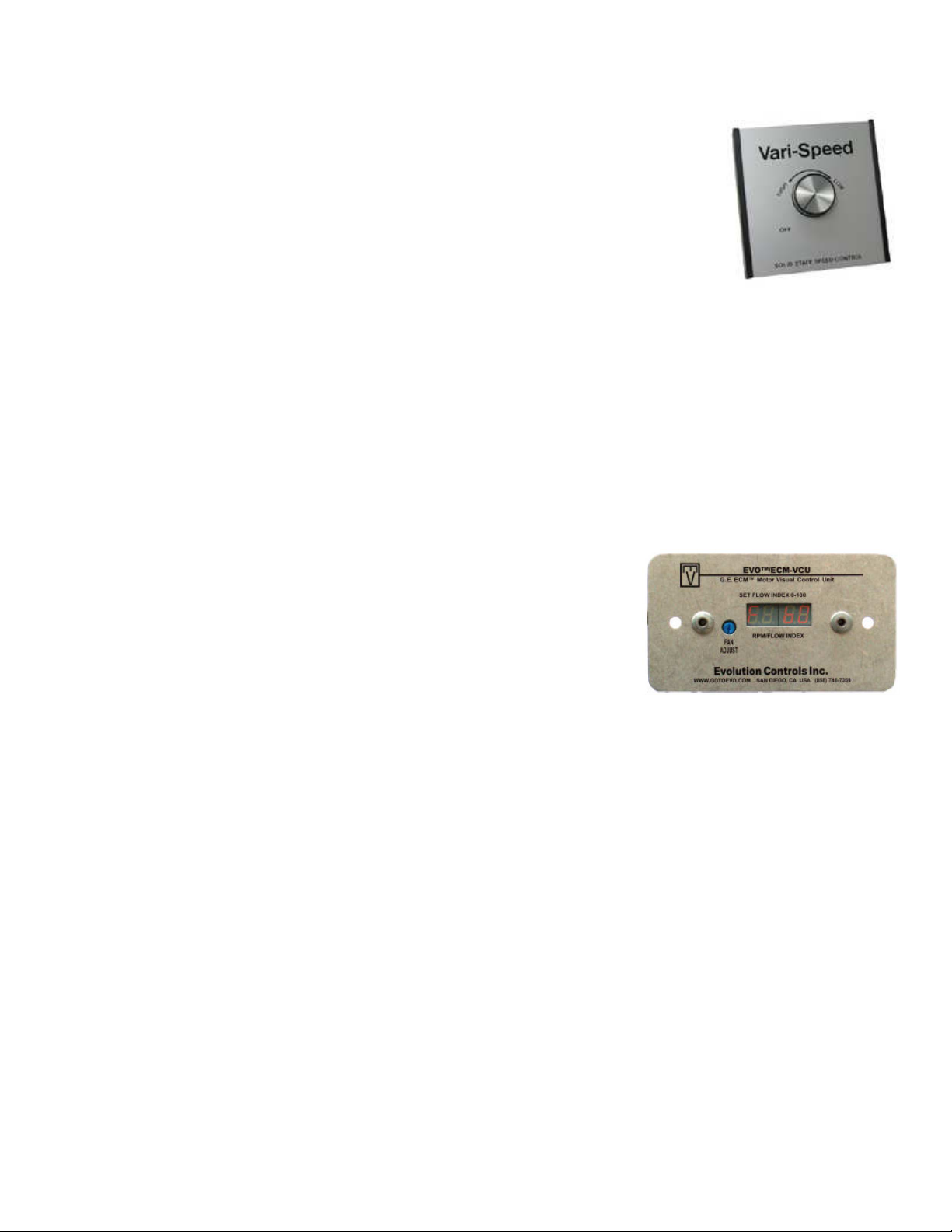
PSC (Permanent Split Capacitor) Motor Speed Control
Some single phase direct drive fans contain speed controls that regulate the amount
of voltage going to the motor. Specific PSC motors must be used in conjunction with
speed controls. The speed control has a knob with an off position, and high to low
range. At high speed, the speed control allows all of the line voltage to pass right to
the motor.
A minimum speed adjustment is provided to allow independent control of the
minimum speed setting. Minimum speed adjustment ensures motor runs with
sufficient torque to prevent stalling. To adjust this:
1) Motor must be in actual operating conditions to achieve proper speed adjustment. Motor will not
slow down unless proper load is applied.
2) Turn main control knob to lowest speed position.
3) Locate and adjust minimum speed setting and adjust with small screw driver. This can be found
under the speed control faceplate. (rotate clockwise to decrease minimum speed; counterclockwise to increase minimum speed).
4) Motor will now operate from this preset minimum speed to full speed.
The lowest minimum voltage that may be applied to these motors is 65VAC. Running lower
voltages to the motor can cause premature failure and overheating problems.
ECM (Electronically Controlled Motor) Speed Control
ECM motors and control allows accurate manual adjustment of fan speed.
The benefit of ECM motors is exceptional efficiency, performance, and
motor life.
The control used with ECM motors features a 4 digit LED numerical
display. The blue knob on the control allows the user to set the flow index
with a screwdriver. Twenty seconds later, the display shows the motor
RPM. Then, the display periodically alternates between the flow index and
motor RPM. The flow index has a range of 0 to 100% and is typically linear with motor RPM.
The ECM control requires a 24 VAC input and can locally turn the motor on and off. The motor can be
adjusted between 300 RPM and maximum speed with this control.
NOTE: To adjust the speed of 3 phase direct drive motors, a variable frequency
drive is required.
Page 11

11
Motorized Intake Damper
On units shipped with the optional motorized intake damper, a power transformer is supplied with the unit
if the main incoming voltage is greater than 120V. The damper motor is automatically energized when
the main disconnect switch is in the ON position. No external wiring to the damper motor is required.
Electric Cabinet Heater
On units shipped with an optional electric cabinet heater, ensure that the heater is wired to a separate
120V, 15 amp input, the thermostat sensing bulb is mounted correctly in the control vestibule where the
heater is located, and the thermostat set to 0 Degrees Fahrenheit.
Remote Control Panel
On units shipped with the optional remote control panel, an electrical drop containing the panel wiring is
provided with the heater. There is a terminal strip inside the remote panel that matches the terminals in
the heater unit. The remote panel should be wired as shown below.
Fire System
Microswitch
NO
NC
BK
OR
WH
GY
BR
RD
PK
RD
BK
BK
OR
WH
GY
BR
RD
PK
RD
BK
C
BK
PR
1
E
BK
OR
WH
GY
BR
RD
PK
RD
BK
BL
BK
OR
WH
GY
BR
RD
PK
RD
BK
Page 12

12
Fan to Building Wiring Connection
OPERATION
Prior to starting up or operating the heater, check all fasteners for tightness. In particular, check the set
screw in the wheel hub, bearings and the fan sheaves (pulleys). With power and gas to the heater OFF or
prior to connecting ventilator to power, turn the fan wheel by hand to be sure it is not striking the inlet or
any obstacles. Re-center if necessary.
Start Up
Special Tools Required
• AC Voltage Meter
• Tachometer
• Standard Hand Tools
Start Up Procedure
1. Check all electrical connections for tightness and continuity.
2. Check pulley alignment and belt tension as described below.
3. Inspect the condition of the intake damper and damper linkage, if provided.
4. Inspect the air-stream for obstructions and install intake filters if missing.
5. Compare the supplied motor voltage with the fan’s nameplate motor voltage. If this does not
match, correct the problem.
6. Start the fan up, by turning the external disconnect to the ON position, and shut it OFF
immediately to check rotation of the wheel with the directional arrow on the blower scroll.
Reversed rotation will result in poor air performance, motor overloading and possible burnout.
For units equipped with a single-phase motor check the motor wiring diagram to change rotation.
For 3-phase motors, any two power leads can be interchanged to reverse motor direction.
7. When the fan is started up, observe the operation and check for any unusual noises.
• Amperage Meter
• Manometer
• Differential Pressure Gauge
Page 13

13
Pilot Adjustment
1. Restart the fan and check the gas supply pressure at the inlet
gas tap upstream of all electronic valves. The inlet pressure
should be 5 in. - 14 in. w.c. If the inlet pressure is too high,
install an additional pressure regulator external to the unit.
2. Open the field installed manual gas shut-off valve and the
manual main gas valve on the combination gas control valve.
3. Call for heat with the intake air thermostat (turn set-point to
temperature above outside air) and allow the pilot to light. If the
pilot does not light, purge the pilot line. If air purging is
required, disconnect the pilot line at the outlet of the pilot valve.
4. A weak pilot flame can be caused by low gas pressure, or a
dirty pilot orifice. To adjust the pilot flame, remove the cap from
the pilot adjustment screw on the combination gas valve.
Increase the pilot gas flow by turning the screw counterclockwise. Decrease the pilot gas flow by turning the screw
clockwise.
5. Once the pilot has been established, open the main manual gas
shut-off valve downstream of the electronic valves. Check to
make sure that the main gas valve opens, and gas flows to the
burner.
Pilot Assembly
Page 14

14
Maxitrol M411 Low Fire
Mod Valve Voltage Summary
Main Burner Adjustment
1. Once the pilot has been properly established, the
manifold gas pressure or temperature rise should be
adjusted to jobsite conditions. The gas pressure
regulator integral to the combination gas control is
Volts DC Firing Mode
0 to 5 VDC Low Fire
5 to 15 VDC Modulation
15 to 20 VDC High Fire
adjusted at the factory for average gas conditions. It is
important that the gas be supplied to the burner in
accordance with the input rating on the rating plate.
2. Create a high fire call for heat. This should be done with the blower on and all gas controls on.
High fire can be achieved by removing the wire at terminal #4 (remove wires #2 and #4 for
Maxitrol 44 systems) from the Maxitrol 14 amplifier.
3. The manifold pressure should be checked
at the pressure tap downstream of the
Av era ge M an ifold Pre ssu re vs. Fi rin g Rate /Ft . of B ur ner
6.00
modulating valve. The graph to the right
indicates the proper manifold pressure for
the desired amount of BTUs per foot of
burner. For natural gas systems, the high
fire manifold pressure should not exceed 5
in. w.c. For propane gas, the high fire
manifold pressure should not exceed 2.5
in. w.c. Another method of checking high
fire is to measure the temperature rise of
the unit. The temperature rise should be
set to design conditions and typically is
minimum 70°F.
4. Remove the cap from the combination gas
valve regulator adjustment. Using the
5.00
4.00
3.00
2.00
1.00
Mani fold Pre ssure (in. w .c.)
0.00
-1.00
0 100000 200000 300000 400000 500000 600000
Natural Gas Propane Gas
Firing Rat e (BT U/Hr /Ft. o f B urne r)
regulator pressure adjusting screw, adjust
the high fire manifold pressure to 5 in. w.c. maximum for natural gas and 2.5 in. w.c. maximum for
propane gas. High fire should be set to generate the desired temperature rise. If the high fire
screw is at the end of its adjustment and more pressure is needed, then adjust the main building
gas pressure regulator spring (located external to the unit) to achieve the proper manifold
pressure. Turning the regulator screw clockwise will increase pressure and counter-clockwise will
decrease pressure.
5. Reconnect the wire on the Maxitrol 14 amplifier at terminal #4 (wires #2 and #4 for Maxitrol 44).
6. The low fire manifold pressure must now be set. Low fire can be achieved by removing the wire
at terminal #5 from the Maxitrol 14 amplifier (remove #8 for Maxitrol 44).
7. Using the bypass screw located on the side of the M411, adjust the low fire manifold pressure
until there is a very thin flame along the entire length of the burner. No
dark spots should be seen in the burner. The burner may be observed
through the view-port located on the external wall of the heater. Replace
Bypass Screw
the cap to the Maxitrol valve and restore all of the original wiring on the
Maxitrol amplifier and gas components.
8. A final gas leak check shall be performed to verify the gas-tightness of the
heater’s components and piping under normal operating conditions. This
can be done by measuring the gas pressure at the ¼” gas plug just
downstream of the modulating valve.
Page 15

15
Heater Start Up Summary
Is incoming gas pressure
5"-14"?
No
Yes
Adjust
incoming gas
pressure.
Adjust pilot flame.
Lock unit into
high fire.
Does high fire produce
at least a 70°F temp
rise and produce the
correct manifold
pressure?
Yes
Lock unit into low fire.
Does thin flame fill
entire burner length?
Yes
No
Adjust high fire
No
Adjust low
fire.
Setting incoming pressure:
Presure must be measured at first "T" in
supply gas line before the first gas valve.
Adjusting the pilot:
To adjust the pilot flame, remove the cap
from the pilot adjustment screw on the
combination gas valve. Increase the pilot
gas flow by turning the screw counterclockwise. Decrease the pilot gas flow by
turning the screw clockwise.
Adjusting high fire:
High fire manifold pressure should be 5"
maximum for natural gas and 2.5"
maximum for propane. High fire should
produce at least a 70°F temperature rise.
Remove wire #4 from the Maxitrol 14
amplifier (#2 and #4 for Maxitrol 44). This
will drive the valve into its full open
position. Adjust high fire with the
regulator inside the unit. Turn clockwise
to increase temperature rise. Replace the
wires on the Maxitrol Amplifier.
Adjusting low fire:
Remove wire #5 from the Maxitrol 14
amplifier (#8 for Maxitrol 44). This will
drive the valve into its lowest position.
Adjust the low fire by turning the low fire
bypass screw on the side of the M411
modulating valve. Refer to the included
Maxitrol literature for more detailed
information. Ensure that the enite length
of burner is filled with a thin flame.
Burner start up
complete.
Page 16

16
Maximum RPM
and
HP Chart
Pulley Adjustment Illustration
Final Start Up Procedure
1. With the air and burner systems in full operation and all ducts attached, measure the system
airflow. Motor sheave (pulley) is variable pitch, and allows for an increase or decrease of the fan
RPM to adjust the airflow, as shown in the illustration below. For your convenience, a RPM chart
is included in the following pages.
2. Once the proper airflow is achieved, measure and record the fan speed with a reliable
tachometer. Caution - Excessive speed will result in motor overloading or bearing failure.
Do not set fan RPMs higher than specified in the maximum RPM chart. See the
troubleshooting guide for more information.
3. Measure and record the voltage and amperage to the motor and compare with the motor
nameplate to determine if the motor is operating under safe load condition.
4. Once the rpm of the ventilator has been properly set, disconnect power and recheck belt tension
and pulley alignment as described below.
Blower Size Maximum RPM Maximum HP
7” 2400 2
Pulley Adjustment
The adjustable motor pulley is factory set for the RPM specified.
Speed can be increased by closing or decreased by opening the
adjustable motor sheave. Two groove variable pitch pulleys must
be adjusted an equal number of turns open or closed. Any
increase in speed represents a substantial increase in
horsepower required by the unit. Motor amperage should always
be checked to avoid serious damage to the motor when the
speed is varied. Always torque setscrews according to the
setscrew torque chart.
Pulley Alignment
Pulley Setscrew Torque
Thread Size Torque (IN/Lb)
No. 10 (bushing) 32
1/4” (bushing) 72
5/16” 130
Proper Belt Tension
Page 17

Flame Safety Controller
Pulley Combination Chart
Pulley Combination Chart
Motor RPM 1725
1/3 to 1-1/2 HP MOTOR PULLEY D d1 Dd2 Pd1 Pd2
AX BELTS 1VP50 3.4 4.4 3.6 4.6
BLOWER PULLEY DATUM DIAMETER PITCH DIAMETER 5 4 1/2 4 3 1/2 3 2 1/2 2 1 1/2 1 1/2 0
AK32H 3 3.2 1941 1995 2048 2102 2156 2210 2264 2318 2 372 2426 2480
1/3 to 1-1/2 HP MOTOR PULLEY D d1 Dd2 Pd1 Pd2
AX BELTS 1VL44 2.8 3.8 3 4
BLOWER PULLEY DATUM DIAMETER PITCH DIAMETER 5 4 1/2 4 3 1/2 3 2 1/2 2 1 1/2 1 1/2 0
AK32H 3 3.2 1617 1671 1725 1779 1833 1887 1941 1995 2 048 2102 2156
1/3 to 2 HP MOTOR PULLEY Dd1 Dd2 Pd1 Pd2
AX BELTS 1VL40 2.4 3.4 2.6 3.6
BLOWER PULLEY DATUM DIAMETER PITCH DIAMETER 5 4 1/2 4 3 1/2 3 2 1/2 2 1 1/2 1 1/2 0
7 IN. BLOWER
AK66 6.2 6.4 701 728 755 782 809 836 863 889 916 943 970
AK54 5 5.2 863 896 929 962 995 1028 1062 1095 1128 1161 1194
AK46 4.2 4.4 1019 1059 1098 1137 1176 1215 1255 1294 1333 1372 1411
AK39 3.5 3.7 1212 1259 1305 1352 1399 1445 1492 1539 1585 1632 1678
AK32 3 3.2 1402 1455 1509 1563 1617 1671 1725 1779 1833 1887 1941
Open Closed
Open Closed
Open Closed
TURNS ON MOTOR PULLEY
TURNS ON MOTOR PULLEY
TURNS ON MOTOR PULLEY
Sequence of Operation
The direct-fired heater is most easily understood when broken down into smaller individual systems.
There are two main systems, a make-up air fan and a heater. The make-up air fan consists of a blower
and motor. The heater may be further broken down into two control systems, the Flame Safety Control
(FSC) and the Modulating Gas System (MGS). The burner mixes air with the gas (Natural or LP) which
heats the air.
Flame Safety Control
The first system to understand is the Flame Safety Control. The FSC
is there only to monitor the flame, NOT to control temperature. The
FSC uses a flame rectification sensor mounted on the pilot assembly
to detect the presence of flame in the burner. The FSC is also wired
into an airflow switch, which tells it whether there is proper airflow
through the unit (not just any airflow, but proper airflow). Proper airflow
occurs when there is a .15 in. w.c. to .80 in. w.c. differential
pressure drop across the burner. The FSC controls the opening of
the redundant solenoid gas valves and the operation of the spark
igniter to initiate a pilot flame upon start-up.
Upon a call for heat, there is a 15 second Pilot Trial For Ignition (PTFI).
During PTFI, the FSC opens the pilot gas valve and allows gas to flow
to the pilot assembly. At the same moment, the spark igniter is started,
causing the spark to ignite the pilot gas. When the flame rod sensor detects the flame it powers the
modulating gas system. This is the normal operating mode. The FSC continues to monitor the flame and
airflow. Once this occurs, the unit is in a main flame cycle and thus powers the main gas valve and the
modulating gas system. This is the normal operating mode. The FSC continues to monitor the flame and
airflow. If the flame fails to light after 15 seconds of sparking, the FSC goes in to lock-out mode. Anytime
this occurs, the problem must be diagnosed and corrected to avoid future lockouts after resetting. To
begin troubleshooting, or to reset the FSC, shut down power to the heater and restart the heater. This
will clear the alarm from the flame safety.
17
Page 18

18
Maxitrol 14
Air Flow Switch
Air Flow Switch
There are both high and low airflow switches contained within one housing
measuring the pressure drop across the burner. This is to insure that there is
proper airflow (.15 in. w.c. to .80 in. w.c.) across the burner and proper
combustion at all times. Both switches are wired in series and have single pole
double throw (one common contact, one normally open contact, and one normally
closed contact) switches that are ‘switched’ by air pressure. There are two airflow
tubes in the heater, located near the burner and profile plate assembly (profile
plates surround the burner and control air into the burner section). In the case of
clogged filters, blocked intake, excessive duct static pressure, or a broken belt, the
correct burner differential pressure may not be achieved, not allowing the low
airflow switch to close. The high airflow switch protects against profile plate
failures that cause excessive airflow through the burner. In the event that the
pressure drop across the burner is not in the range of the airflow switch, gas flow
to the burner is stopped by the Flame Safety Control.
The graphs below illustrate the approximate cfm going through the unit vs. the differential pressure
measured by the airflow switch. Simply measure the differential profile pressure drop at the airflow tubes
in the unit and match that value up to the matching unit curve below. This will show the cfms traveling
through the burner and will indicate proper airflow or airflow problems (too much or not enough). If the
pressure drop is outside of the .15” to .80” range, the blower rpm should be adjusted to fix airflow.
76 Prof ile Cha rt
1800
1600
1400
1200
CFM
1000
800
600
400
0.15 0.2 0.25 0.3 0.35 0.4 0.45 0.5 0.55 0.6 0.65 0.7 0.75 0.8
Burner Differentia l Profil e Pressure (in. w .c.)
Modulating Gas System
The second system, the Maxitrol modulating gas system, consists of a temperature
selector dial, a discharge air sensor, an amplifier, and a modulating gas valve. The two
types of Maxitrol systems used are the Maxitrol 14 series or the Maxitrol 44 series. The
Maxitrol 14 utilizes a discharge air sensor and modulates the Maxitrol gas valve to provide
discharge air to match the selected temperature on the temperature selector. The Maxitrol
44 utilizes a room temperature sensor to control room temperature as well as a discharge
air sensor in order to control the discharge air temperature. The modulating gas valve
controls the amount of gas flow to the burner based on the temperature rise needed.
When the modulating gas valve is all the way open and achieving the maximum BTUs and
temperature rise of the unit, it is called “high fire”.
Amplifier
Page 19

19
High Temperature Li
mit
High Temperature Limit
One of the back up safety device is the high temperature limit switch.
This switch is a mechanical thermostat that measures the temperature
inside the unit downstream of the burner. If the factory-set temperature
of 180°F is exceeded, it will signal the FSC to turn off the burner. This
requires a manual reset of the high temperature limit. This insures that
the discharge does not exceed 185°F.
Operation Summary
With the blower already running and the airflow switch proven;
The outside air temperature falls below the setting of intake air thermostat
The optional remote panel is set to “Manual” and “Heat” mode
• The FSC in energized and the following occurs;
FSC indicates that it has power
FSC verifies proper Airflow
Begins a 15 second Pilot Trial For Ignition
The pilot gas solenoid valve is opened, the spark igniter begins sparking, and the flamerod
sensor watches for flame initiation
When flame is established, the main valve opens and the FSC powers the Maxitrol system
and gas flow begins modulating
The FSC monitors the flame while the Maxitrol system adjusts to the selected temperature
•
The Maxitrol system checks the discharge air temperature (and the room temperature for the Maxitrol
44) and regulates the gas going to the burner to satisfy the temperature setting. The Maxitrol system
will modulate the main burner gas from 100% down to 5% as needed.
or
Page 20

20
Optional Remote Panel Circuit
Power
Supply
From Heater
Blower Switch
"Auto"
Power is Sent to
Heater to Open
Damper (if
provided) and
Start Blower
"Blower On"
Light
On
"Power" LightOnOff
Panel is
Powered
Damper is not
Open or Freeze-
Stat has Detected
Off
Low Temperature
No Power
to Panel
(3-Position Panels
Operation
"Off"
Position
Only)
"Manual"
Nothing Happens
No Power is Sent
to Heater
Power is Sent to
Heater to Open
Damper (if
provided) and
Start Blower
"Blower On"
Light
On
Off
Damper is not
Open or FreezeStat has Detected
Low Temperature
Operation
Nothing Happens
Intake Air is
Warmer
Than
Thermostat
Set-Point
Thermostat Set -Point
Heat Circuit is Energized
"Burner On" Light Illum inates
Intake Air
Thermstat is
Powered
Intake Air is Cooler
Than
with proper flame.
Blower Operates
Cooling Circuit is
Energized
"Cool"
Position
(if
provided)
Temperature
Heat Circuit is Energized
"Burner On" Light Illum inates
with proper flame.
Control
Switch
"Heat"
Position
Position
"Vent"
Blower Operates
Heat Does not
Operate
Page 21

21
Components
The following image and list outlines the typical direct fired heater components and their functions.
2
11
12
9
3
8
13
5
6
1
16
14
7
17
19
4
22
10
23
18
20
21
15
1. Gas Inlet – Main gas supply connection
2. Motor Starter – Contactor with overload protection to start and protect motor.
3. Freeze-Stat Thermostat (Optional) – De-energizes blower motor if the discharge air
temperature falls below the set point.
4. Cooling Interlock Relay (Optional) – Energizes power to cooling circuit on call for cooling.
5. Inlet Gas Pressure Gauge (Optional) – Inlet gas pressure should be measured here.
6. Combination Gas Valve - A combination of redundant solenoid valves, pilot valve and gas
regulator built into one unit.
7. Pilot Tubing – Pilot tube connection to combination gas valve.
8. Manual Reset High Temperature Limit – Safety device that prevents the heater from
overheating.
9. Maxitrol Modulating Amplifier - Regulates temperature by modulating gas valve
10. Power Transformer – Installed when motor voltage > 120V. Used to provide 120V service to
controls.
11. Circuit Breaker – Protects electrical components from high current spikes.
12. Terminal Strip – Central location to terminate control wiring. Should be used for troubleshooting.
13. Control Transformer – 120V primary; 24V secondary control transformer.
14. Low Pressure Airflow Probe – Measures profile pressure downstream of burner.
15. High Pressure Airflow Probe – Measures profile pressure upstream of burner.
16. Modulating Gas Valve – Modulates gas flow to burner to provide proper air temperature.
17. Manifold Gas Pressure Tap – Manifold gas pressure should be measured here.
18. Flame Safety Control – Initiates and monitors flame.
19. Airflow Switch – A safety device insuring proper air flow during burner operation.
20. Intake Air Thermostat – De-energize heating circuit when intake air exceeds set-point.
21. Damper Actuator (Optional) – Motor containing end switch that opens intake damper.
22. Manual Gas Shut-Off Valve - Allows gas flow to burner to be shut off to leak test gas train
23. Auxiliary Cooling Thermostat (Optional)– Dry contacts for cooling connection
Page 22

22
Remote Panel Option
1
2
3
4
The Remote Panel is a device used to control the operation of the heater from a remote location. This
unit is available in both a “2 Position” or “3 Position” configuration and with or without a cooling output. It
also will accommodate both the Maxitrol discharge temperature dial and the Maxitrol space sensing
Selectrastat. It is important to understand the following Remote Panel controls and uses:
1. Manual/Off/Auto Switch - Used to control blower operation and tempering mode of unit. The
AUTO position allows the unit to “decide”, through the use of the intake air thermostat, whether or
not heating is needed. The MANUAL position allows the user to control whether or not heat is
needed. The OFF position will turn the blower off when a “3 Position” remote panel is ordered.
The OFF position will disable all temperature controls when a “2 Position” remote panel is
ordered and fan power is then controlled by the pre-wire package only.
2. Heat/Vent Switch – This switch is powered when the Manual/Off/Auto switch is in the MANUAL
position. It is used to control the tempering mode of the unit. The VENT position will prevent the
burner from operating and the heater will deliver untempered air. The HEAT position will force
the burner on and the unit will heat the incoming air. This switch becomes a Heat/Vent/Cool
switch when the cooling interlock is ordered. This option provides a 120V cooling output from the
remote panel.
3. Lights- Displays the current status of unit features. The light definitions are as follows:
POWER - Illuminated when there is power to Remote Panel.
BLOWER ON - Illuminated when the blower motor is powered.
BURNER ON - Illuminates after pilot flame has established and main valve is powered.
4. Temperature Control – Controls the discharge temperature of a standard unit. The temperature
dial is replaced with Maxitrol Selectrastat in Space Heating applications and is used to control the
space temperature.
Page 23

23
Troubleshooting
The following tables list causes and corrective actions for possible problems with direct fired heater units.
Review these lists prior to consulting manufacturer.
Airflow Troubleshooting Chart
Problem
Fan Inoperative Blown fuse or open circuit breaker Replace fuse or reset circuit breaker
Motor Overload Fan rotating in the wrong direction Be sure fan is rotating in the direction
Insufficient Airflow Fan rotating in the wrong direction Be sure fan is rotating in the direction
Excessive Airflow Blower speed to high Reduce fan RPM
Excessive Vibration and Noise Misaligned pulleys Align pulleys
Potential Cause
Disconnect switch in “Off” position Turn to “On” position
Motor wired incorrectly Check motor wiring to wiring diagram
Broken fan belt Replace belt
Motor starter overloaded Reset starter and check amps
Remote panel set to “Off” Position Set Remote Panel to “Manual” or
Fan speed is too high Reduce fan RPM
Motor wired incorrectly Check motor wiring to wiring diagram
Overload in starter set too low Set overload to motor FLA value
Motor HP too low Determine if HP is sufficient for job
Duct static pressure lower than design Reduce fan RPM
Poor outlet conditions There should be a straight clear duct
Intake damper not fully open Inspect damper linkage and replace
Duct static pressure higher than
design
Blower speed too low Increase fan RPM. Do not overload
Supply grills or registers closed Open and adjust
Dirty or clogged filters Clean and/or replace
Belt slippage Adjust belt tension
Filters not installed Install filters
Duct static pressure lower than design Reduce fan RPM
Damaged or unbalanced wheel Replace wheel
Fan is operating in the unstable region
of the fan curve
Bearings need lubrication or
replacement
Fan speed is too high Reduce fan RPM
Belts too loose, worn or oily Inspect and replace if needed
Corrective Action
and check amps
located on fan motor
“Auto” Position
shown on rotation label
located on fan motor
shown on rotation label
at the outlet
damper motor if needed
Improve ductwork to eliminate or
reduce duct losses
motor
Refer to performance curve for fan
Lubricate or replace
Page 24

24
Burner Troubleshooting Chart
Proper Spark Gap
Problem
Pilot Does Not Light/Stay Lit Main gas if off Open main gas valve
Main Burner Does Not Light
(Pilot is Lit)
Not Enough Heat Main gas pressure too low Increase main gas pressure – do not
Too Much Heat Defective modulating gas valve Check/replace modulating valve
Potential Cause
Air in gas line Purge gas line
Dirt in pilot orifice Clean orifice with compressed air
Gas pressure out of range Adjust to proper gas pressure
Pilot valve is off Turn pilot valve on
Pilot orifice fitting leak Tighten pilot orifice
Excessive drafts Re-direct draft away from unit
Safety device has cut power Check limits and airflow switch
Dirty flame sensor Clean flame sensor
Remote panel in “Vent” mode Change to “Heat” mode
No spark at igniter Check wiring, sensor, and ignition
Defective valve Replace combination valve
Loose valve wiring Check wiring to valve
Defective pilot sensor Replace pilot sensor
Shut off valve closed Open shut off valve
Defective flame safety controller Replace flame safety controller
Pilot fails as main gas valves open
and main gas begins to flow
Too much airflow Decrease airflow if possible
Burner undersized Check design conditions
Gas controls not wired properly Check wiring
Thermostat setting too low Increase thermostat setting
Thermostat malfunction Check/replace thermostat
Unit locked into low fire Check wiring
Thermostat setting too high Decrease thermostat setting
Unit locked into high fire Check wiring
Thermostat wired incorrectly Check thermostat wiring
Corrective Action
controller. Check spark gap as shown
below.
Plug the first burner port next to the
pilot gas tube with burner cement
exceed 14 in. w.c. inlet pressure
Page 25

25
Remote Panel Troubleshooting Chart
Light Indication
No Lights Power not available to Remote Panel Bad voltage to unit
POWER Light Only Proper unit Off Operation No problem
POWER Light and
BLOWER ON Light
POWER Light and
BLOWER ON Light and
BURNER ON Light
Condition
No power to motor starter Manual/Off/Auto Switch in “Off” Position
Proper Ventilation Operation No Problem
No Power to Flame Safety Controller Manual/Off/Auto Switch in “Off” Position
Improper Airflow Excessive Airflow
Proper Heating Operation No Problem
Possible Cause
Main disconnect in “OFF” Position
Circuit breaker tripped
Bad main transformer
(3 Position Remote Panels Only)
Improper damper function
Low Temperature Thermostat Timed
Out (Option)
(2 Position Remote Panels Only)
Heat/Vent Switch in “Vent” Position
High Temperature Limit Thermostat
Tripped
Manual/Off/Auto Switch in “Auto”
Position and Intake Air Thermostat not
Satisfied
Insufficient Airflow
Bad airflow switch
Problem with air probes
Problem with airflow tubing
Broken Belt
Filters Dirty or Need Replacement
Page 26

26
Nothing
Happens
Is Overload
tripped on
starter?
NO
Is Freeze-Stat
open?
NO
Is end switch on
Motorized
Damper closed?
Reset & measure FLA
YES
of motor. Is it high er
YES
NO
Troubleshooting Flowcharts
than rating?
Adjust or
Replace
Adjust or
Replace
actuator
YES
Adjust
or
change
Pulley
Blower runs
but there is
no heat
Check airflo w across
the burne r, there should be
between .15 an d .65
differenti al pressure (in. w.c.
Is outside air cooler than
intake air thermostat
YES
setting?
YES
Is High Temp.
Limit Tripped?
NO
Is there a
Remote Panel
Installed?
YES
Is Remote set to
"Heat"
YES
Refer to Flame
Safety Guide
NO
YES
NO
NO
Adjust pulley to
achieve proper
NO
Check wiring
"Manual" and
"Heat" mode.
airflow.
Proper
economizer
operation
Reset
Set Remote
Panel to
Burner lights but
heater stays in
Low Fire
Is there voltage on
Terminal #17
Yes
Are all valves
powered and open?
Yes
With wires 3 & 4
removed from the
Maxitrol Amplif ier, is
there 9.5K to 11K
Ohms between the
wires?
Yes
Remove Terminal #4
from the Maxitrol
Amplifier. Does t he
heater go into High F ire?
Yes
With wires 1 & 2
removed from the
Maxitrol Amplif ier, is
there 9.5K to 11K Ohms
between the wires ?
No
Replace
FSC
No
Check valve wiring
or open valves
Replace
No
Discharge Air
Is there a short or open
No
circuit i n Modulating
Valve? Should be 45-55
Ohms (60-80 on MR212)
No
Replace
Amplifier
Replace the
No
Temperature
Selector
Sensor
Yes
Replace
Modulating
Valve
Burner lights but heater
stays in High Fire
Is there a jumper between
terminals 2 & 3 on the
Maxitrol Amplifier?
Yes
Is there a short circuit in
the Remote Temperature
Selector or wiring?
No
Is there an open circuit in
the Discharge Air Sensor
or wiring?
No
Is Plunger in the
Modulating Valve jammed?
Inspect and clean. It
should operate freely in
the sleeve.
No
Foreign object holding
valve open. Remove
bottom plate and inspect
valve and seat. Clean or
replace valve.
No
Yes
Yes
Install
Jumper
Repair short or
replace
Temperature
Selector
Repair Circuit or
replace the
Discharge Air
Sensor
Page 27

27
MAINTENANCE
To guarantee trouble free operation of this heater, the manufacturer suggests following these guidelines.
Most problems associated with fan failures are directly related to poor service and maintenance.
Please record any maintenance or service performed on this fan in the documentation section located at
the end of this manual.
WARNING: DO NOT ATTEMPT MAINTENANCE ON THE HEATER UNTIL THE
ELECTRICAL SUPPLY HAS BEEN COMPLETELY DISCONNECTED AND THE
MAIN GAS SUPPLY VALVE HAS BEEN TURNED OFF.
General Maintenance
1. Fan inlet and approaches to ventilator should be kept clean and free from any obstruction.
2. Motors are normally permanently lubricated. Check bearings periodically. If they have grease
fittings lubricate each season. Use caution when lubricating bearings, wipe the fittings clean, the
unit should be rotated by hand while lubricating. Caution: Use care when touching the exterior
of an operating motor. Motors normally run hot and may be hot enough to be painful or
cause injury.
3. All fasteners should be checked for tightness each time maintenance checks are preformed prior
to restarting unit.
4. Blowers require very little attention when moving clean air. Occasionally oil and dust may
accumulate causing imbalance. If the fan is installed in a corrosive or dirty atmosphere,
periodically inspect and clean the wheel, inlet and other moving parts to ensure smooth and safe
operation.
Re-Setting Of The Unit
If the flame safety control is locked out, reset the unit by:
1. Turn OFF Power to the unit.
2. Turn Power to the unit back ON.
Emergency shutdown of unit
To shut down the unit in the event of an emergency do the following:
1. Turn power OFF to the unit from main building disconnect.
2. Turn the external disconnect switch to the OFF position.
3. CLOSE the inlet gas valve located on the heater.
Prolonged shutdown of the unit
For prolonged shutdown the following steps should be done:
1. Turn the external disconnect switch to the OFF position.
2. CLOSE the inlet gas valve located on the heater.
To re-start the unit the following steps should be done:
1. Turn the external disconnect switch to the ON position.
2. OPEN the inlet gas valve located on the heater.
Page 28

28
2 weeks after startup
1. Belt tension should be checked after the first 2 weeks of fan operation. Belts tend to stretch and
settle into pulleys after an initial start-up sequence. Do not tension belts by changing the
setting of the motor pulley, this will change the fan speed and may damage the motor. To retension belts, turn the power to the fan motor OFF. Loosen the fasteners that hold the blower
scroll plate to the blower. Rotate the motor to the left or right to adjust the belt tension. Belt
tension should be adjusted to allow 1/64” of deflection per inch of belt span. Exercise extreme
care when adjusting V-belts as not to misalign pulleys. Any misalignment will cause a sharp
reduction in belt life and produce squeaky noises. Over-tightening will cause excessive belt and
bearing wear as well as noise. Too little tension will cause slippage at startup and uneven wear.
Whenever belts are removed or installed, never force belts over pulleys without loosening
motor first to relieve belt tension. When replacing belts, use the same type as supplied by the
manufacturer. On units shipped with double groove pulleys, matched belts should always be
used.
2. All fasteners should be checked for tightness each time maintenance checks are preformed prior
to restarting unit.
Every 3 months
1. Belt tension should be checked quarterly. See instructions in the previous maintenance section.
Over-tightening will cause excessive bearing wear and noise. Too little tension will cause
slippage at startup and uneven wear.
2. Filters need to be cleaned and/or replaced quarterly, and more often in severe conditions.
Washable filters can be washed in warm soapy water. When re-installing filters, be sure to install
with the airflow in the correct direction as indicated on the filter.
Filter Quantity Chart
Intake 16” x 20”
76 1
Yearly
1. Inspect bearings for wear and deterioration. Replace if necessary.
2. Inspect belt wear and replace torn or worn belts.
3. Inspect bolts and set screws for tightness. Tighten as necessary.
4. Inspect motor for cleanliness. Clean exterior surfaces only. Remove dust and
grease from the motor housing to ensure proper motor cooling. Remove dirt
and grease from the wheel and housing to prevent imbalance and damage.
5. Check for gas leaks and repair if present.
6. Clean flame sensor by rubbing with steel wool to remove any rust build-up,
7. Clean burner with a wire brush and insure burner ports are free of debris.
Then wipe the burner with a clean rag.
Burner Orifice
Drill Size
Orifice Drill Size
Gas Port 31
Air Port 43
Page 29

Start-Up and Maintenance Documentation
START-UP AND MEASUREMENTS SHOULD BE PERFORMED AFTER THE SYSTEM HAS BEEN
AIR BALANCED AND WITH THE HEAT ON (Warranty will be void without completion of this form)
Job Information
Job Name Service Company
Address Address
City City
State State
Zip Zip
Phone Number Phone Number
Fax Number Fax Number
Contact Contact
Purchase Date Start-Up Date
Heater Information
Refer to the start-up procedure in this manual to complete this section.
Name Plate and Unit Information
Model Number
Serial Number
Motor Volts
Motor Hertz
Motor Phase
Motor FLA
Motor HP
Blower Pulley
Motor Pulley
Belt Number
Gas Type
Min. Btu/Hr
Max. Btu/Hr
**
If measured amps exceed the FLA rating on the nameplate, fan RPM must be reduced to decrease the
measured amps below the nameplate FLA rating.
Field Measured Information
Motor Voltage
Motor Amperage**
RPM
Burner Differential Pressure in. w.c.
Gas Type
High Fire Inlet Gas Pressure in. w.c.
Low Fire Manifold Gas Pressure in. w.c.
High Fire Manifold Gas Pressure in. w.c.
Thermostat Set-Point
Temperature Control Discharge
Space
Airflow Direction Correct
Incorrect
Maintenance Record
Date Service Performed
Factory Service Department
Phone: 1-866-784-6900
Fax: 1-919-554-2415
29
Page 30

30
August 2013 Rev. 9
Page 31

31
August 2013 Rev. 9
Page 32

32
August 2013 Rev. 9
 Loading...