


ThermaCAM™PM575/595
Operator’s Manual

USA Tel: +1 (503) 684-3731 Fax:+1 (503) 684-3207
Sweden Tel: +46(0) 8 753 27 50 Fax:+46(0) 8 755 07 52
France Tel: +33(0)1 41 33 97 97 Fax:+33(0)1 47 36 18 32
Germany Tel: +49(0) 6995 0090-0 Fax:+49(0)6995 0090-40
Italy Tel: +39(0) 2-3909121 Fax: +39(0) 2-39005185
UK Tel: +44(0) 1732 220011 Fax: +44(0) 1732 220014

ThermaCAM™PM575/595
Operator’s Manual
©FLIR Systems AB, May 1999 – Publ. No.557 369– Ed. A


[Table of contents]
Table of contents
1 General information 1
1.1 Warranty 1
1.2 Copyright 1
1.3 Quality Assurance 2
2 Introduction 3
2.1 System overview 3
2.2 Unpacking and assembly 3
3 Controls and connections 6
3.1 Direct access buttons 6
3.2 Connections 7
4 Getting started 9
4.1 Adjusting and connecting system components 9
4.1.1 Lenses 9
4.1.2 PC-card 9
4.1.3 Battery 9
4.1.4 Shoulder strap 9
4.1.5 Headset 10
4.2 First time operation 10
4.2.1 To get an image 10
4.2.2 To set a new language 10
4.2.3 To measure a temperature 11
4.2.4 To save an image 11
4.2.5 To add a voice comment to an image 11
4.2.6 To add text comments to an image 11
4.2.7 To recall a stored image and listen to a
voice comment 12
4.2.8 To recall a previously stored image and view
text comments 12
5 Operation 14
5.1 User interface 14
5.2 Menu objects 15
5.3 Menu area 18
5.3.1 Control box 18
5.3.2 Dialog boxes 18
5.3.3 Confirm boxes 19
© FLIR Systems AB – Publ. No. 557 369 – Ed. A
i

[Table of contents]
5.3.4 Result table 20
5.3.5 Data presentation 20
5.3.6 Temperature scale 21
5.3.7 Status area 21
5.3.8 Joystick control 21
5.3.9 Critical information 22
5.4 File System 22
5.4.1 Advantages with digital recording 22
5.4.2 File organisation 22
5.4.3 Naming files and directories 23
5.4.4 Naming files and directories in a PC 24
5.5 Menu Functions 24
5.5.1 File menu 24
5.5.1.1 Open... 24
5.5.1.2 Save 25
5.5.1.3 Periodic save… 26
5.5.1.4 Voice comment... 26
5.5.1.4.1Voice comment info panel 27
5.5.1.5 Text comment... 27
5.5.1.6 Delete image... 28
5.5.1.7 Directory... 29
5.5.1.8 Report comment… 29
5.5.1.8.1Report comment info panel 29
5.5.2 Analysis menu 30
5.5.2.1 Obj par... 30
5.5.2.2 Ref temp 31
5.5.2.3 Spot 31
5.5.2.4 Area 32
5.5.2.5 Profile 32
5.5.2.6 Isotherm 33
5.5.3 Image menu 33
5.5.3.1 Man adjust... 33
5.5.3.1.1 Level 33
5.5.3.1.2 Span 34
5.5.3.1.3 Temp range 34
5.5.3.2 Freeze 34
5.5.3.3 Auto adjust 34
5.5.3.3.1 Auto palette 34
5.5.3.4 Image only 34
5.5.4 Setup menu 35
5.4.4.1 Analysis... 35
ii
ThermaCAM™ PM575/595 Operator’s Manual

[Table of contents]
5.5.4.1.1 Spot 35
5.5.4.1.2 Area type 35
5.5.4.1.3 Area function 36
5.5.4.1.4 Profile 36
5.5.4.1.5 Isotherm type 36
5.5.4.1.6 Isotherm width 36
5.5.4.1.7 Isotherm colour 36
5.5.4.1.8 Difference temp 37
5.5.4.1.9 Multiple spots 37
5.5.4.2 Image... 37
5.5.4.2.1 Auto adjust 37
5.5.4.2.2 Continuous adjust 37
5.5.4.2.3 Colour scale 37
5.5.4.2.4 Saturation col. 38
5.5.4.2.5 Data field 38
5.5.4.2.6 Data background 38
5.5.4.2.7 Text comments 38
5.5.4.2.8 Scale 39
5.5.4.3 Local adapt... 39
5.5.4.4 Save options... 39
5.5.4.4.1 Image storage 39
5.5.4.4.2 Prompt comment? 40
5.5.4.4.3 Image naming 40
5.5.4.4.4 Image file type 40
5.5.4.4.5 BMP file content 40
5.5.4.5 Date & Time... 40
5.5.4.6 System Info... 40
6 Battery system 42
6.1 Battery 42
6.2 Battery charging 43
6.3 Useful notes on the battery system 43
7 Technical specifications 44
7.1 General specifications 44
7.2 Input & output connectors 46
7.2.1 12 V socket 46
7.2.2 Headset socket 47
7.2.3 Video socket 47
7.2.4 Battery charger 47
© FLIR Systems AB – Publ. No. 557 369 – Ed. A
iii

[Table of contents]
7.2.5 Power supply (optional) 48
7.3 Lens data 48
8 Thermographic measurement techniques 49
8.1 Introduction 49
8.2 Emissivity 49
8.2.1 Finding the emissivity of an object 50
8.2.1.1 Using a thermocouple 50
8.2.1.2 Using reference emissivity 50
8.3 Ambient temperature 50
8.4 Distance 50
8.5 Relative humidity 50
9 Theory of thermography 51
9.1 Introduction 51
9.2 The electromagnetic spectrum 51
9.3 Blackbody radiation 52
9.3.1 Planck’s law 52
9.3.2 Wien’s displacement law 54
9.3.3 The Stefan-Boltzmann law 55
9.3.4 Non-blackbody emitters 55
9.4 Infrared semi-transparent materials 57
iv
ThermaCAM™ PM575/595 Operator’s Manual

[1 — General information]
1 General information
1.1 Warranty
All products manufactured by FLIR Systems AB are warranted against defective
materials and workmanship for a period of one (1) year from the delivery date of
the original purchase, provided such products have been under normal storage,
use and service, and in accordance with FLIR’s instruction.
All products not manufactured by FLIR included in systems delivered by FLIR to
the original purchaser carry the warranty, if any, of the particular supplier only and
FLIR has no responsibility whatsoever for such products.
The warranty extends only to the original purchaser and is not transferable. It is not
applicable to any product which has been subjected to misuse, neglect, accident
or abnormal conditions of operation. Expendable parts are excluded from the warranty.
In the case of a defect in a product covered by this warranty the product must not
be further used in order to prevent additional damage. The purchaser shall
promptly report any defect to FLIR or this warranty will not apply.
FLIR will, at its option, repair or replace any such defective product free of charge
if, upon inspection, it proves to be defective in material or workmanship and provided that it is returned to FLIR within the said one-year period.
FLIR has no other obligation or liability for defects than those set forth above.
No other warranty is expressed or implied. FLIR specifically disclaims the implied
warranties of merchantability and fitness for a particular purpose.
FLIR shall not be liable for any direct, indirect, special, incidental or consequential
loss or damage, whether based on contract, tort or any other legal theory.
1.2 Copyright
© FLIR Systems AB, 1999. All rights reserved worldwide. No parts of the soft-
ware including source code may be reproduced, transmitted, transcribed or translated into any language or computer language in any form or by any means, electronic, magnetic, optical, manual or otherwise, without the prior written permission
of FLIR Systems AB, P.O. Box 3, SE-182 11 Danderyd, Sweden.
This manual must not, in whole or part, be copied, photocopied, reproduced,
translated or transmitted to any electronic medium or machine readable form without prior consent, in writing, from FLIR Systems AB.
© FLIR Systems AB – Publ. No. 557 369 – Ed. A
1

[1.3 — Quality Assurance]
1.3 Quality Assurance
The Quality Management System under which these products are developed and
manufactured has been certified in accordance with the standard for ISO 9001.
FLIR Systems AB is committed to a policy of continuous development; therefore
we reserve the right to make changes and improvements on any of the products
described in this manual without prior notice.
All functions described in this manual are not available in both camera models.
2
ThermaCAM™ PM575/595 Operator’s Manual

[2 — Introduction]
2 Introduction
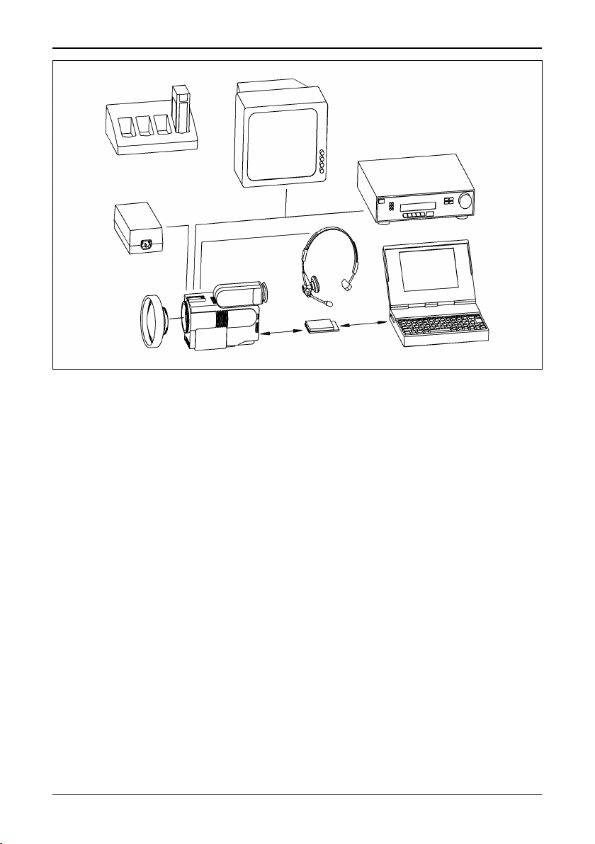
2.1 System overview
The ThermaCAM™ PM575/595 infrared condition monitoring system consists of
an IR-camera with a built-in 24° lens, a removable battery pack and a range of
accessories. The IR-camera measures and images the emitted infrared radiation
from an object. The fact that radiation is a function of object surface temperature
makes it possible for the camera to calculate and display this temperature.
The ThermaCAM™ PM575/595 camera is dust- and splash-proof and shock- and
vibration-tested for use in the most demanding field conditions. It is a handheld,
truly portable camera, which is lightweight and operates for more than 1.5 hours
on one battery pack. A high-resolution colour image is provided in real-time either
in the integral viewfinder or on an external monitor.
The camera is very easy to use and is operated by using a few buttons which are
conveniently placed on the camera, allowing fingertip control of major functions. A
built-in menu system also gives easy access to an advanced, simple-to-use camera software for increased functionality.
To document the object under inspection it is possible to capture and store
images onto a removable PC-card. It is also possible to store, together with every
image, voice comments and/or text comments, including information such as the
object’s ID data, field conditions etc. This is achieved by making use of the headset connected to the camera.
The images can be analysed either in the field by using the real-time measurement
functions built into the camera, or in a PC by using the AGEMA™ Report soft-
ware.
The PC-card is moved from the camera to the PC. In the PC the images cannot
only be viewed and analysed, but the voice comment can also be played back.
AGEMA™ Report makes it very easy to create complete survey reports (containing numerous IR images, photos, tables etc.) from the inspections.
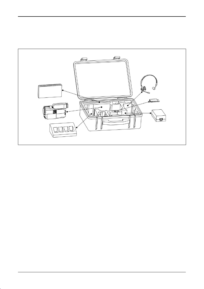
2.2 Unpacking and assembly
On receipt of your ThermaCAM™ PM575/595 remove each component from the
carrying case and inspect them all against the delivery note.
© FLIR Systems AB – Publ. No. 557 369 – Ed. A
3
[2.2 — Unpacking and assembly]
Figure 2.1 System overview.
The ThermaCAM™ PM575/595 system is delivered in a transport case. The system comprises:
• ThermaCAM™ PM575/595 camera with a built-in 24° lens.
• PC-card.
• Batteries (2).
• Fast charger with cable.
• Shoulder strap.
• Video cable.
• Lens cap.
• Operator’s Manual.
• Calibration protocol.
• Transport case.
• Headset.
Optional accessories:
• Power supply with cable.
• 7° lens.
• 12° lens.
• 45° lens.
• 80° lens.
• Extension cable, 5 m (16.4 ft).
4
ThermaCAM™ PM575/595 Operator’s Manual
[2.2 — Unpacking and assembly]
• PC software, AGEMA™ Report.
• High temperature options.
• Remote control handle.
• Camera handle.
Figure 2.2 How to pack the ThermaCAM™ PM575/595 in the transport case.
© FLIR Systems AB – Publ. No. 557 369 – Ed. A
5
[3 — Controls and connections]
3 Controls and connections
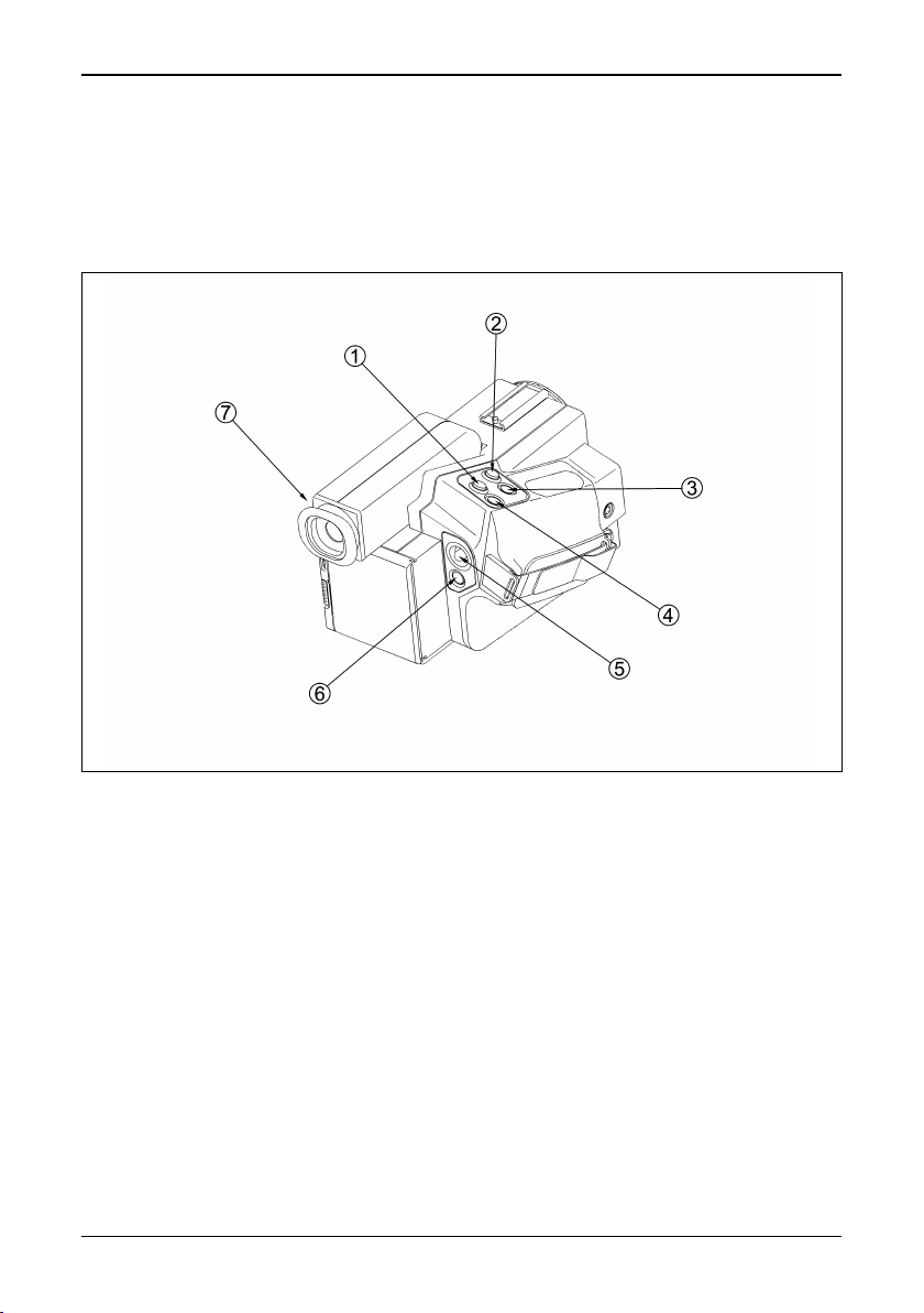
3.1 Direct access buttons
The camera is controlled by pressing the direct access buttons and/or using the
joystick control.
Figure 3.1 Direct access buttons
The ↵ (enter) button [1] brings up the menu system of the camera in the viewfinder. Make your selection in the menu by using the joystick control. You accept
the menu choice and quit the menu mode by pressing the
also means Accept or Confirm.
Press the A (auto) button [2] to get the best image in the viewfinder automatically.
When this button is pressed an automatic calibration is also performed.
Press the S (save) button [3] shortly to switch between a frozen image and a live
image. To store the image to the PC-card press the S button for more than 1 sec.
The C (clear) button [4] is used when you need to skip a menu selection without
making any changes and leave the menu mode. The C button also means Escape
or Don’t accept.
6
ThermaCAM™ PM575/595 Operator’s Manual
↵ button. The ↵ button

[3.2 — Connections]
The joystick [5] has various functions. At the start up of the camera the joystick is
in the default mode controlling focus (up/down) and zoom (left/right). In the menu
mode you use the joystick to select the appropriate function and to increase or
decrease various parameter settings.
The green (on/off) button [6] is used to switch the power of the camera on and
off. Press the button to switch the camera on. Keep down the button for more than
2 seconds to switch the camera off.
The focus of the viewfinder [7]can be adjusted by turning the adjustment ring
either clockwise or counter-clockwise.
For further information on the direct access buttons, see “User interface” on page
14.
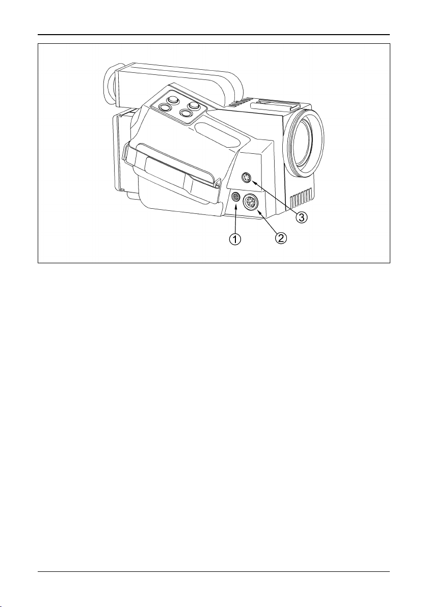
3.2 Connections
There are three connectors on the camera:
• 12 VDC connector: For connection to the power cable from battery belt or
power supply. This connector also provides S-VHS signals (or on some camera
models 14-bit digital signals) and remote control signals when the optional 5
metres (16.4 ft) extension cable is used.
• Headset connector: For connection to a headset to make voice comments to
stored images.
• Video connector: For connection to large monitors or standard VHS-video
equipment for viewing or recording.
[1] Video connector
[2] 12 VDC connector
[3] Headset connector
(Overleaf)
© FLIR Systems AB – Publ. No. 557 369 – Ed. A
7
[3.2 — Connections]
Figure 3.2 Camera connectors.
8
ThermaCAM™ PM575/595 Operator’s Manual

[4 — Getting started]
4 Getting started
4.1 Adjusting and connecting system components
4.1.1 Lenses
The camera is equipped with a built-in 24° lens, but optional lenses can also be fitted.
[1] To mount the lens push the lens carefully into the bayonet of the camera, align-
ing the white dots on the camera bayonet and the lens. Turn the lens 45° clock-
wise to lock the lens.
[2] To release the lens turn it 45° counter-clockwise and remove the lens.
[3] The lens type is recognised by the camera and the correct calibration is auto-
matically used.
4.1.2 PC-card
The recorded images with voice and text comments are stored on a removable
PC-card.
[1] To insert the PC-card open the hatch by pressing the release button on the
back of the camera downwards. Insert the disk with the connector side (i.e. the
bottom side of the disk) to the right and the connectors facing the camera.
[2] To remove the PC-card open the hatch and press the eject button.
After the PC-card has been inserted, the camera software will check that it hasn’t
got any errors. This will be indicated in the viewfinder by the words Checking disk.
4.1.3 Battery
[1] To insert the battery pack open the hatch by pressing the release button down-
wards on the back of the camera. Insert the battery with the connectors facing
the camera and with its convex side facing downwards.
[2] To remove the battery open the hatch and press the battery release button
below the battery.
See also “Battery system” on page 42.
4.1.4 Shoulder strap
[1] To fit the shoulder strap to the camera, pull back the safety clasp at the end of
the shoulder strap by pressing the release button.
© FLIR Systems AB – Publ. No. 557 369 – Ed. A
9

[4.1.5 — Headset]
[2] Pass the thin straps through the slots on the left and right back side of the
camera. Insert the wire hook through the holes at the end of the straps. Lock
the mechanism by pulling forward the safety clasp.
[3] Adjust the length of the shoulder strap so that the camera rests comfortably on
the chest.
4.1.5 Headset
[1] Connect the headset to the headset connector of the camera.
[2] Place the headset on your head with the plastic support above your ear on the
opposite side of the headphone.
[3] Adjust the position of the microphone to about 2–3 cm from your mouth.
The headset can be used with the headphone either to the left or to the right. On
the cable there is also a clip to fasten the cable to the operator.
4.2 First time operation
4.2.1 To get an image
[1] Insert the battery into the battery compartment on the back of the camera.
[2] Remove the lens cover from the camera.
[3] Press the green on/off button to start the camera. After approx. 15 seconds an
image with the FLIR logotype will appear and will be displayed until the camera
controls are ready for use.
[4] Adjust the viewfinder focus to obtain the best display focus for your eyes.
[5] Point the camera at a warm object to be viewed, like a face or a hand.
[6] Press the A button to activate the auto-adjust function to achieve in a good
image in the viewfinder.
[7] Adjust the focus of the camera by moving the joystick up/down.
4.2.2 To set a new language
If the camera is set to the wrong language, press the
system.
[1] Go to Local adapt… in the Set-up menu (Setup
which makes the Setup – Local adaptations panel appear.
[2] Choose Language (Setup
language by moving the joystick to the right or left. When the correct language
is shown press
10
↵ to set the language.
→Local adapt…→Language) and select the desired
ThermaCAM™ PM575/595 Operator’s Manual
↵ button to display the menu
→Local adapt…). Press ↵

[4.2.3 — To measure a temperature]
4.2.3 To measure a temperature
[1] Press the
[2] Go to the Spot function in the menu tree by moving the joystick to the left or
the right. The Spot function is located in the Analysis menu. Press the
when Spot is highlighted. The spot meter crosshair will now appear in the
image and the measured temperature will be shown in the upper right corner
of the display. If the multiple spots option is selected in the setup menu (Set-
→Analysis→Multiple spots→On), the Analysis menu will display Spot 1,
up
Spot 2 and Spot 3 instead of Spot.
[3] To move the spot meter crosshair on the screen the function has to be high-
lighted in the Analysis menu. It can then be moved with the joystick. When the
spot is correctly located, press
stick (i.e. controlling focus and zoom). To be able to move the spot meter after
the joystick has resumed its normal function, it has to be highlighted and con-
firmed in the Analysis menu again.
4.2.4 To save an image
[1] Press the A button and focus the image.
[2] Press the S button to freeze the image.
[3] To save, hold down the S button for one second or until the filename (e.g.
E123232) of the image appears.
Press the S button briefly to go to live mode.
↵ button to display the menu system.
↵ button
↵ to go back to the normal function of the joy-
4.2.5 To add a voice comment to an image
[1] Connect the headset to the headset connector and place it on your head. See
also “Connections” on page 7.
[2] Press the A button and focus the image.
[3] Freeze the image by pressing the S button for a short while.
[4] Press the ↵ to get the menu system and go to Voice comment... in the File
menu by using the joystick. Select Voice comment... by pressing
make the control panel for voice comments appear.
[5] Hold down the S button while recording. The length of the comment is indi-
cated by * signs in the control bar.
[6] Playback in the headphone indicates that the recording is working.
[7] When the voice recording is complete press the
image and the voice comment.
[8] To listen to the comment keep down the A button.
4.2.6 To add text comments to an image
This function is only possible if a file containing user-defined text comments is
stored on the PC-card. These text comments can be created and edited in
© FLIR Systems AB – Publ. No. 557 369 – Ed. A
↵ button to save both the
↵
↵. This will
11

[4.2.7 — To recall a stored image and listen to a voice comment]
AGEMA™ Report PC software. See the software Operator’s Manual for further
information on creating and editing text comments.
[1] Press the A button and focus the image.
[2] Freeze the image by pressing the S button for a short while.
[3] Select Text comment… in the File menu. This brings up a maximum of four
consecutive multiple-choice panels.
[4] Move the joystick up/down to choose the desired text comment. Move the joy-
stick left/right to go to the next text comment panel, or to return to a previous
one.
[5] Press
The suffix T after the image file name indicates that a text comment is attached to
the file.
4.2.7 To recall a stored image and listen to a voice comment
N.B. – The symbol after an image filename denotes that a voice comment is
attached to the image file.
↵ to save the complete text comment in the last panel.
[1] Press the
[2] Go to the Open function in the File menu by moving the joystick to the left or
the right. Press the
ing files will now appear at the bottom of the screen.
[3] To choose the image you would like to open move the joystick up and down. If
the image is in another directory go to the directory selection box by moving
the joystick to the right. When the desired image file name appears, press
select the image.
[4] To listen to the voice message go to the Voice comment... function in the File
menu. Press the
for Voice comment... will now appear on the right side of the screen.
[5] To play back and listen to the message keep down the A button. To remove the
Voice comment... dialog panel, press the C button.
[6] To get back to live mode again, press the S button.
4.2.8 To recall a previously stored image and view text comments
N.B. – The letter T after an image filename indicates that text comments are
attached to the image file.
[1] Press the
[2] Go to the Open function in the File menu by moving the joystick to the left or
the right. Press the
ing files will now appear at the bottom of the screen.
[3] To choose the image you would like to open move the joystick up and down. If
the image is in another directory go to the directory selection box by moving
↵ button to display the menu system.
↵ button when Open is highlighted. A control bar for open-
↵ to
↵ button when Voice comment... is highlighted. A dialog panel
↵ button to display the menu system.
↵ button when Open is highlighted. A control bar for open-
12
ThermaCAM™ PM575/595 Operator’s Manual

[4.2.8 — To recall a previously stored image and view text comments]
the joystick to the right. When the desired image file name appears, press
select the image.
If Text comments: None is selected in the Setup – Image dialog box (Setup
→Text comments→None):
age
[4] Select Text comment… in the File menu when the image is shown. A dialog
box will appear and the current text comments are displayed at the bottom of
the screen, above the data fields.
If Text comments: Value only or Text comments: Value and label is presently
selected in the Setup – Image dialog box (Setup
[5] The current text comments are displayed at the bottom of the screen – above
the data fields – when the image is opened.
→Image):
↵ to
→Im-
© FLIR Systems AB – Publ. No. 557 369 – Ed. A
13
 Loading...