

Page 1

ThermaCAM™PM575/595
Operator’s Manual
Page 2

USA Tel: +1 (503) 684-3731 Fax:+1 (503) 684-3207
Sweden Tel: +46(0) 8 753 27 50 Fax:+46(0) 8 755 07 52
France Tel: +33(0)1 41 33 97 97 Fax:+33(0)1 47 36 18 32
Germany Tel: +49(0) 6995 0090-0 Fax:+49(0)6995 0090-40
Italy Tel: +39(0) 2-3909121 Fax: +39(0) 2-39005185
UK Tel: +44(0) 1732 220011 Fax: +44(0) 1732 220014
Page 3

ThermaCAM™PM575/595
Operator’s Manual
©FLIR Systems AB, May 1999 – Publ. No.557 369– Ed. A
Page 4

Page 5

[Table of contents]
Table of contents
1 General information 1
1.1 Warranty 1
1.2 Copyright 1
1.3 Quality Assurance 2
2 Introduction 3
2.1 System overview 3
2.2 Unpacking and assembly 3
3 Controls and connections 6
3.1 Direct access buttons 6
3.2 Connections 7
4 Getting started 9
4.1 Adjusting and connecting system components 9
4.1.1 Lenses 9
4.1.2 PC-card 9
4.1.3 Battery 9
4.1.4 Shoulder strap 9
4.1.5 Headset 10
4.2 First time operation 10
4.2.1 To get an image 10
4.2.2 To set a new language 10
4.2.3 To measure a temperature 11
4.2.4 To save an image 11
4.2.5 To add a voice comment to an image 11
4.2.6 To add text comments to an image 11
4.2.7 To recall a stored image and listen to a
voice comment 12
4.2.8 To recall a previously stored image and view
text comments 12
5 Operation 14
5.1 User interface 14
5.2 Menu objects 15
5.3 Menu area 18
5.3.1 Control box 18
5.3.2 Dialog boxes 18
5.3.3 Confirm boxes 19
© FLIR Systems AB – Publ. No. 557 369 – Ed. A
i
Page 6

[Table of contents]
5.3.4 Result table 20
5.3.5 Data presentation 20
5.3.6 Temperature scale 21
5.3.7 Status area 21
5.3.8 Joystick control 21
5.3.9 Critical information 22
5.4 File System 22
5.4.1 Advantages with digital recording 22
5.4.2 File organisation 22
5.4.3 Naming files and directories 23
5.4.4 Naming files and directories in a PC 24
5.5 Menu Functions 24
5.5.1 File menu 24
5.5.1.1 Open... 24
5.5.1.2 Save 25
5.5.1.3 Periodic save… 26
5.5.1.4 Voice comment... 26
5.5.1.4.1Voice comment info panel 27
5.5.1.5 Text comment... 27
5.5.1.6 Delete image... 28
5.5.1.7 Directory... 29
5.5.1.8 Report comment… 29
5.5.1.8.1Report comment info panel 29
5.5.2 Analysis menu 30
5.5.2.1 Obj par... 30
5.5.2.2 Ref temp 31
5.5.2.3 Spot 31
5.5.2.4 Area 32
5.5.2.5 Profile 32
5.5.2.6 Isotherm 33
5.5.3 Image menu 33
5.5.3.1 Man adjust... 33
5.5.3.1.1 Level 33
5.5.3.1.2 Span 34
5.5.3.1.3 Temp range 34
5.5.3.2 Freeze 34
5.5.3.3 Auto adjust 34
5.5.3.3.1 Auto palette 34
5.5.3.4 Image only 34
5.5.4 Setup menu 35
5.4.4.1 Analysis... 35
ii
ThermaCAM™ PM575/595 Operator’s Manual
Page 7

[Table of contents]
5.5.4.1.1 Spot 35
5.5.4.1.2 Area type 35
5.5.4.1.3 Area function 36
5.5.4.1.4 Profile 36
5.5.4.1.5 Isotherm type 36
5.5.4.1.6 Isotherm width 36
5.5.4.1.7 Isotherm colour 36
5.5.4.1.8 Difference temp 37
5.5.4.1.9 Multiple spots 37
5.5.4.2 Image... 37
5.5.4.2.1 Auto adjust 37
5.5.4.2.2 Continuous adjust 37
5.5.4.2.3 Colour scale 37
5.5.4.2.4 Saturation col. 38
5.5.4.2.5 Data field 38
5.5.4.2.6 Data background 38
5.5.4.2.7 Text comments 38
5.5.4.2.8 Scale 39
5.5.4.3 Local adapt... 39
5.5.4.4 Save options... 39
5.5.4.4.1 Image storage 39
5.5.4.4.2 Prompt comment? 40
5.5.4.4.3 Image naming 40
5.5.4.4.4 Image file type 40
5.5.4.4.5 BMP file content 40
5.5.4.5 Date & Time... 40
5.5.4.6 System Info... 40
6 Battery system 42
6.1 Battery 42
6.2 Battery charging 43
6.3 Useful notes on the battery system 43
7 Technical specifications 44
7.1 General specifications 44
7.2 Input & output connectors 46
7.2.1 12 V socket 46
7.2.2 Headset socket 47
7.2.3 Video socket 47
7.2.4 Battery charger 47
© FLIR Systems AB – Publ. No. 557 369 – Ed. A
iii
Page 8

[Table of contents]
7.2.5 Power supply (optional) 48
7.3 Lens data 48
8 Thermographic measurement techniques 49
8.1 Introduction 49
8.2 Emissivity 49
8.2.1 Finding the emissivity of an object 50
8.2.1.1 Using a thermocouple 50
8.2.1.2 Using reference emissivity 50
8.3 Ambient temperature 50
8.4 Distance 50
8.5 Relative humidity 50
9 Theory of thermography 51
9.1 Introduction 51
9.2 The electromagnetic spectrum 51
9.3 Blackbody radiation 52
9.3.1 Planck’s law 52
9.3.2 Wien’s displacement law 54
9.3.3 The Stefan-Boltzmann law 55
9.3.4 Non-blackbody emitters 55
9.4 Infrared semi-transparent materials 57
iv
ThermaCAM™ PM575/595 Operator’s Manual
Page 9

[1 — General information]
1 General information
1.1 Warranty
All products manufactured by FLIR Systems AB are warranted against defective
materials and workmanship for a period of one (1) year from the delivery date of
the original purchase, provided such products have been under normal storage,
use and service, and in accordance with FLIR’s instruction.
All products not manufactured by FLIR included in systems delivered by FLIR to
the original purchaser carry the warranty, if any, of the particular supplier only and
FLIR has no responsibility whatsoever for such products.
The warranty extends only to the original purchaser and is not transferable. It is not
applicable to any product which has been subjected to misuse, neglect, accident
or abnormal conditions of operation. Expendable parts are excluded from the warranty.
In the case of a defect in a product covered by this warranty the product must not
be further used in order to prevent additional damage. The purchaser shall
promptly report any defect to FLIR or this warranty will not apply.
FLIR will, at its option, repair or replace any such defective product free of charge
if, upon inspection, it proves to be defective in material or workmanship and provided that it is returned to FLIR within the said one-year period.
FLIR has no other obligation or liability for defects than those set forth above.
No other warranty is expressed or implied. FLIR specifically disclaims the implied
warranties of merchantability and fitness for a particular purpose.
FLIR shall not be liable for any direct, indirect, special, incidental or consequential
loss or damage, whether based on contract, tort or any other legal theory.
1.2 Copyright
© FLIR Systems AB, 1999. All rights reserved worldwide. No parts of the soft-
ware including source code may be reproduced, transmitted, transcribed or translated into any language or computer language in any form or by any means, electronic, magnetic, optical, manual or otherwise, without the prior written permission
of FLIR Systems AB, P.O. Box 3, SE-182 11 Danderyd, Sweden.
This manual must not, in whole or part, be copied, photocopied, reproduced,
translated or transmitted to any electronic medium or machine readable form without prior consent, in writing, from FLIR Systems AB.
© FLIR Systems AB – Publ. No. 557 369 – Ed. A
1
Page 10

[1.3 — Quality Assurance]
1.3 Quality Assurance
The Quality Management System under which these products are developed and
manufactured has been certified in accordance with the standard for ISO 9001.
FLIR Systems AB is committed to a policy of continuous development; therefore
we reserve the right to make changes and improvements on any of the products
described in this manual without prior notice.
All functions described in this manual are not available in both camera models.
2
ThermaCAM™ PM575/595 Operator’s Manual
Page 11

[2 — Introduction]
2 Introduction
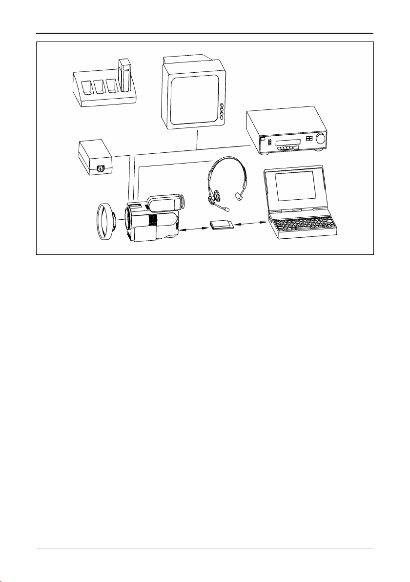
2.1 System overview
The ThermaCAM™ PM575/595 infrared condition monitoring system consists of
an IR-camera with a built-in 24° lens, a removable battery pack and a range of
accessories. The IR-camera measures and images the emitted infrared radiation
from an object. The fact that radiation is a function of object surface temperature
makes it possible for the camera to calculate and display this temperature.
The ThermaCAM™ PM575/595 camera is dust- and splash-proof and shock- and
vibration-tested for use in the most demanding field conditions. It is a handheld,
truly portable camera, which is lightweight and operates for more than 1.5 hours
on one battery pack. A high-resolution colour image is provided in real-time either
in the integral viewfinder or on an external monitor.
The camera is very easy to use and is operated by using a few buttons which are
conveniently placed on the camera, allowing fingertip control of major functions. A
built-in menu system also gives easy access to an advanced, simple-to-use camera software for increased functionality.
To document the object under inspection it is possible to capture and store
images onto a removable PC-card. It is also possible to store, together with every
image, voice comments and/or text comments, including information such as the
object’s ID data, field conditions etc. This is achieved by making use of the headset connected to the camera.
The images can be analysed either in the field by using the real-time measurement
functions built into the camera, or in a PC by using the AGEMA™ Report soft-
ware.
The PC-card is moved from the camera to the PC. In the PC the images cannot
only be viewed and analysed, but the voice comment can also be played back.
AGEMA™ Report makes it very easy to create complete survey reports (containing numerous IR images, photos, tables etc.) from the inspections.
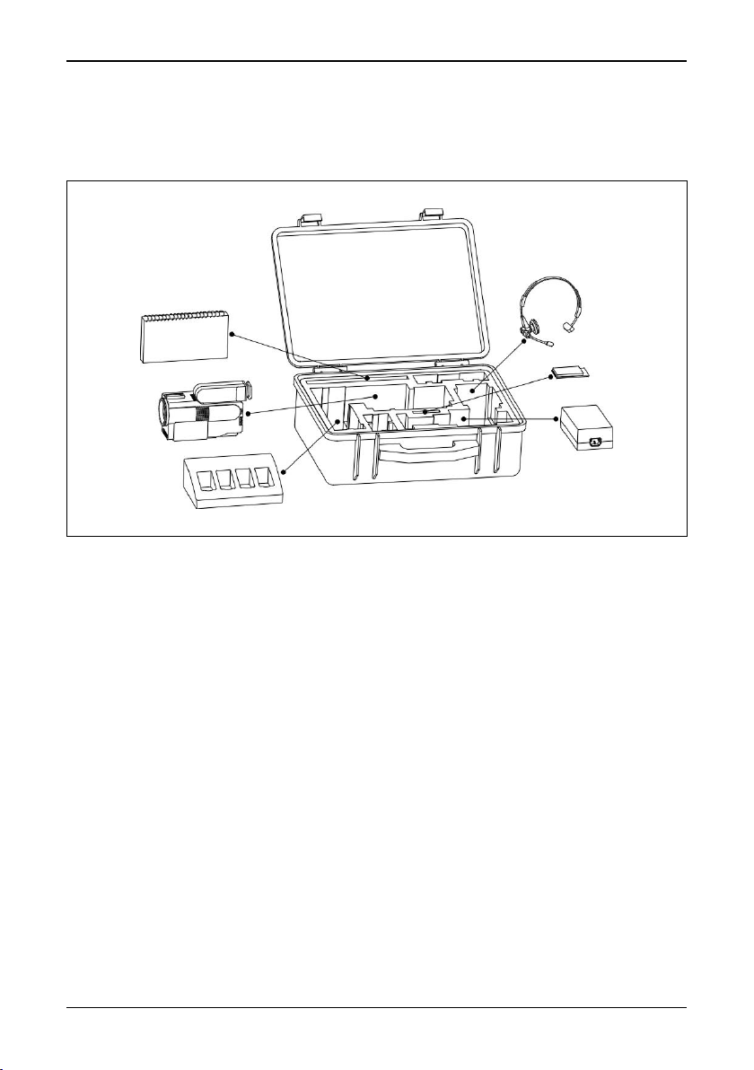
2.2 Unpacking and assembly
On receipt of your ThermaCAM™ PM575/595 remove each component from the
carrying case and inspect them all against the delivery note.
© FLIR Systems AB – Publ. No. 557 369 – Ed. A
3
Page 12
[2.2 — Unpacking and assembly]
Figure 2.1 System overview.
The ThermaCAM™ PM575/595 system is delivered in a transport case. The system comprises:
• ThermaCAM™ PM575/595 camera with a built-in 24° lens.
• PC-card.
• Batteries (2).
• Fast charger with cable.
• Shoulder strap.
• Video cable.
• Lens cap.
• Operator’s Manual.
• Calibration protocol.
• Transport case.
• Headset.
Optional accessories:
• Power supply with cable.
• 7° lens.
• 12° lens.
• 45° lens.
• 80° lens.
• Extension cable, 5 m (16.4 ft).
4
ThermaCAM™ PM575/595 Operator’s Manual
Page 13
[2.2 — Unpacking and assembly]
• PC software, AGEMA™ Report.
• High temperature options.
• Remote control handle.
• Camera handle.
Figure 2.2 How to pack the ThermaCAM™ PM575/595 in the transport case.
© FLIR Systems AB – Publ. No. 557 369 – Ed. A
5
Page 14
[3 — Controls and connections]
3 Controls and connections
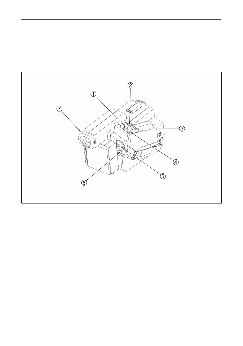
3.1 Direct access buttons
The camera is controlled by pressing the direct access buttons and/or using the
joystick control.
Figure 3.1 Direct access buttons
The ↵ (enter) button [1] brings up the menu system of the camera in the viewfinder. Make your selection in the menu by using the joystick control. You accept
the menu choice and quit the menu mode by pressing the
also means Accept or Confirm.
Press the A (auto) button [2] to get the best image in the viewfinder automatically.
When this button is pressed an automatic calibration is also performed.
Press the S (save) button [3] shortly to switch between a frozen image and a live
image. To store the image to the PC-card press the S button for more than 1 sec.
The C (clear) button [4] is used when you need to skip a menu selection without
making any changes and leave the menu mode. The C button also means Escape
or Don’t accept.
6
ThermaCAM™ PM575/595 Operator’s Manual
↵ button. The ↵ button
Page 15

[3.2 — Connections]
The joystick [5] has various functions. At the start up of the camera the joystick is
in the default mode controlling focus (up/down) and zoom (left/right). In the menu
mode you use the joystick to select the appropriate function and to increase or
decrease various parameter settings.
The green (on/off) button [6] is used to switch the power of the camera on and
off. Press the button to switch the camera on. Keep down the button for more than
2 seconds to switch the camera off.
The focus of the viewfinder [7]can be adjusted by turning the adjustment ring
either clockwise or counter-clockwise.
For further information on the direct access buttons, see “User interface” on page
14.
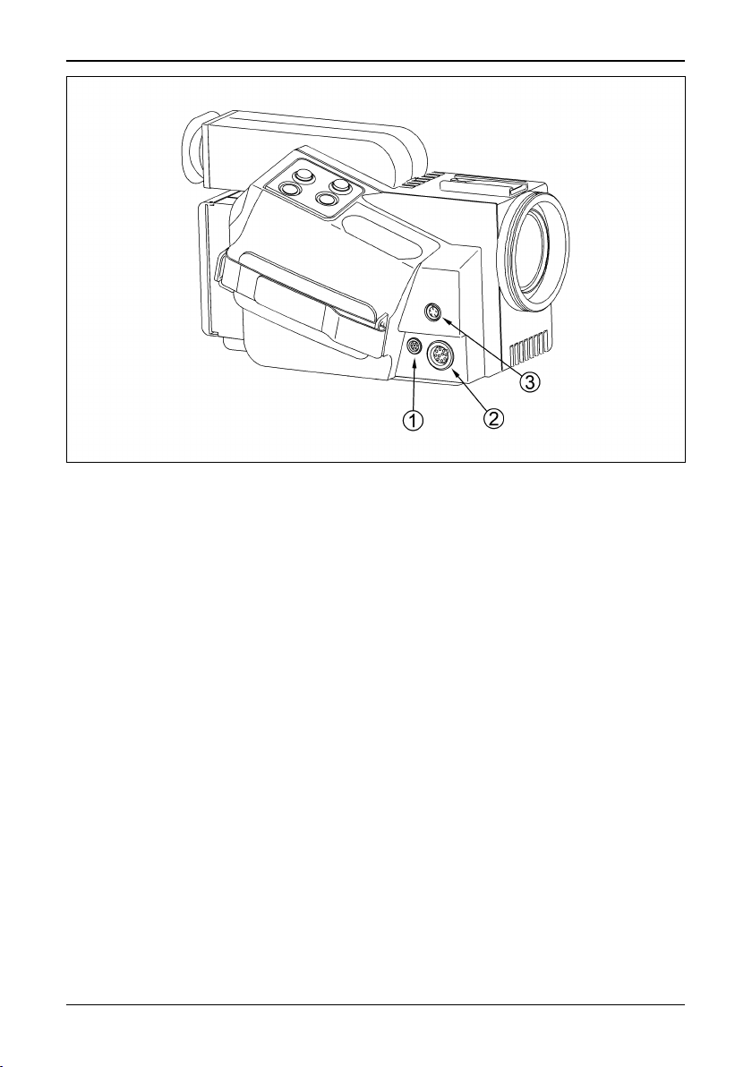
3.2 Connections
There are three connectors on the camera:
• 12 VDC connector: For connection to the power cable from battery belt or
power supply. This connector also provides S-VHS signals (or on some camera
models 14-bit digital signals) and remote control signals when the optional 5
metres (16.4 ft) extension cable is used.
• Headset connector: For connection to a headset to make voice comments to
stored images.
• Video connector: For connection to large monitors or standard VHS-video
equipment for viewing or recording.
[1] Video connector
[2] 12 VDC connector
[3] Headset connector
(Overleaf)
© FLIR Systems AB – Publ. No. 557 369 – Ed. A
7
Page 16
[3.2 — Connections]
Figure 3.2 Camera connectors.
8
ThermaCAM™ PM575/595 Operator’s Manual
Page 17

[4 — Getting started]
4 Getting started
4.1 Adjusting and connecting system components
4.1.1 Lenses
The camera is equipped with a built-in 24° lens, but optional lenses can also be fitted.
[1] To mount the lens push the lens carefully into the bayonet of the camera, align-
ing the white dots on the camera bayonet and the lens. Turn the lens 45° clock-
wise to lock the lens.
[2] To release the lens turn it 45° counter-clockwise and remove the lens.
[3] The lens type is recognised by the camera and the correct calibration is auto-
matically used.
4.1.2 PC-card
The recorded images with voice and text comments are stored on a removable
PC-card.
[1] To insert the PC-card open the hatch by pressing the release button on the
back of the camera downwards. Insert the disk with the connector side (i.e. the
bottom side of the disk) to the right and the connectors facing the camera.
[2] To remove the PC-card open the hatch and press the eject button.
After the PC-card has been inserted, the camera software will check that it hasn’t
got any errors. This will be indicated in the viewfinder by the words Checking disk.
4.1.3 Battery
[1] To insert the battery pack open the hatch by pressing the release button down-
wards on the back of the camera. Insert the battery with the connectors facing
the camera and with its convex side facing downwards.
[2] To remove the battery open the hatch and press the battery release button
below the battery.
See also “Battery system” on page 42.
4.1.4 Shoulder strap
[1] To fit the shoulder strap to the camera, pull back the safety clasp at the end of
the shoulder strap by pressing the release button.
© FLIR Systems AB – Publ. No. 557 369 – Ed. A
9
Page 18

[4.1.5 — Headset]
[2] Pass the thin straps through the slots on the left and right back side of the
camera. Insert the wire hook through the holes at the end of the straps. Lock
the mechanism by pulling forward the safety clasp.
[3] Adjust the length of the shoulder strap so that the camera rests comfortably on
the chest.
4.1.5 Headset
[1] Connect the headset to the headset connector of the camera.
[2] Place the headset on your head with the plastic support above your ear on the
opposite side of the headphone.
[3] Adjust the position of the microphone to about 2–3 cm from your mouth.
The headset can be used with the headphone either to the left or to the right. On
the cable there is also a clip to fasten the cable to the operator.
4.2 First time operation
4.2.1 To get an image
[1] Insert the battery into the battery compartment on the back of the camera.
[2] Remove the lens cover from the camera.
[3] Press the green on/off button to start the camera. After approx. 15 seconds an
image with the FLIR logotype will appear and will be displayed until the camera
controls are ready for use.
[4] Adjust the viewfinder focus to obtain the best display focus for your eyes.
[5] Point the camera at a warm object to be viewed, like a face or a hand.
[6] Press the A button to activate the auto-adjust function to achieve in a good
image in the viewfinder.
[7] Adjust the focus of the camera by moving the joystick up/down.
4.2.2 To set a new language
If the camera is set to the wrong language, press the
system.
[1] Go to Local adapt… in the Set-up menu (Setup
which makes the Setup – Local adaptations panel appear.
[2] Choose Language (Setup
language by moving the joystick to the right or left. When the correct language
is shown press
10
↵ to set the language.
→Local adapt…→Language) and select the desired
ThermaCAM™ PM575/595 Operator’s Manual
↵ button to display the menu
→Local adapt…). Press ↵
Page 19

[4.2.3 — To measure a temperature]
4.2.3 To measure a temperature
[1] Press the
[2] Go to the Spot function in the menu tree by moving the joystick to the left or
the right. The Spot function is located in the Analysis menu. Press the
when Spot is highlighted. The spot meter crosshair will now appear in the
image and the measured temperature will be shown in the upper right corner
of the display. If the multiple spots option is selected in the setup menu (Set-
→Analysis→Multiple spots→On), the Analysis menu will display Spot 1,
up
Spot 2 and Spot 3 instead of Spot.
[3] To move the spot meter crosshair on the screen the function has to be high-
lighted in the Analysis menu. It can then be moved with the joystick. When the
spot is correctly located, press
stick (i.e. controlling focus and zoom). To be able to move the spot meter after
the joystick has resumed its normal function, it has to be highlighted and con-
firmed in the Analysis menu again.
4.2.4 To save an image
[1] Press the A button and focus the image.
[2] Press the S button to freeze the image.
[3] To save, hold down the S button for one second or until the filename (e.g.
E123232) of the image appears.
Press the S button briefly to go to live mode.
↵ button to display the menu system.
↵ button
↵ to go back to the normal function of the joy-
4.2.5 To add a voice comment to an image
[1] Connect the headset to the headset connector and place it on your head. See
also “Connections” on page 7.
[2] Press the A button and focus the image.
[3] Freeze the image by pressing the S button for a short while.
[4] Press the ↵ to get the menu system and go to Voice comment... in the File
menu by using the joystick. Select Voice comment... by pressing
make the control panel for voice comments appear.
[5] Hold down the S button while recording. The length of the comment is indi-
cated by * signs in the control bar.
[6] Playback in the headphone indicates that the recording is working.
[7] When the voice recording is complete press the
image and the voice comment.
[8] To listen to the comment keep down the A button.
4.2.6 To add text comments to an image
This function is only possible if a file containing user-defined text comments is
stored on the PC-card. These text comments can be created and edited in
© FLIR Systems AB – Publ. No. 557 369 – Ed. A
↵ button to save both the
↵
↵. This will
11
Page 20

[4.2.7 — To recall a stored image and listen to a voice comment]
AGEMA™ Report PC software. See the software Operator’s Manual for further
information on creating and editing text comments.
[1] Press the A button and focus the image.
[2] Freeze the image by pressing the S button for a short while.
[3] Select Text comment… in the File menu. This brings up a maximum of four
consecutive multiple-choice panels.
[4] Move the joystick up/down to choose the desired text comment. Move the joy-
stick left/right to go to the next text comment panel, or to return to a previous
one.
[5] Press
The suffix T after the image file name indicates that a text comment is attached to
the file.
4.2.7 To recall a stored image and listen to a voice comment
N.B. – The symbol after an image filename denotes that a voice comment is
attached to the image file.
↵ to save the complete text comment in the last panel.
[1] Press the
[2] Go to the Open function in the File menu by moving the joystick to the left or
the right. Press the
ing files will now appear at the bottom of the screen.
[3] To choose the image you would like to open move the joystick up and down. If
the image is in another directory go to the directory selection box by moving
the joystick to the right. When the desired image file name appears, press
select the image.
[4] To listen to the voice message go to the Voice comment... function in the File
menu. Press the
for Voice comment... will now appear on the right side of the screen.
[5] To play back and listen to the message keep down the A button. To remove the
Voice comment... dialog panel, press the C button.
[6] To get back to live mode again, press the S button.
4.2.8 To recall a previously stored image and view text comments
N.B. – The letter T after an image filename indicates that text comments are
attached to the image file.
[1] Press the
[2] Go to the Open function in the File menu by moving the joystick to the left or
the right. Press the
ing files will now appear at the bottom of the screen.
[3] To choose the image you would like to open move the joystick up and down. If
the image is in another directory go to the directory selection box by moving
↵ button to display the menu system.
↵ button when Open is highlighted. A control bar for open-
↵ to
↵ button when Voice comment... is highlighted. A dialog panel
↵ button to display the menu system.
↵ button when Open is highlighted. A control bar for open-
12
ThermaCAM™ PM575/595 Operator’s Manual
Page 21

[4.2.8 — To recall a previously stored image and view text comments]
the joystick to the right. When the desired image file name appears, press
select the image.
If Text comments: None is selected in the Setup – Image dialog box (Setup
→Text comments→None):
age
[4] Select Text comment… in the File menu when the image is shown. A dialog
box will appear and the current text comments are displayed at the bottom of
the screen, above the data fields.
If Text comments: Value only or Text comments: Value and label is presently
selected in the Setup – Image dialog box (Setup
[5] The current text comments are displayed at the bottom of the screen – above
the data fields – when the image is opened.
→Image):
↵ to
→Im-
© FLIR Systems AB – Publ. No. 557 369 – Ed. A
13
Page 22

[5 — Operation]
5 Operation
5.1 User interface
The most important functions can be accessed with the buttons described below.
Figure 5.1 User interface.
Enter button [1] — This button (marked ↵) has different functions depending on
which mode the camera is in i.e. normal (focus/zoom) mode or menu mode. However, the
Pressing
menu mode.
Pressing
• Activates the selected function or command in the menus.
• Confirms and leaves the selected choices.
Auto-adjust button [2] — Press the button (marked A) to set the best image. The
camera will automatically adjust the viewed temperature span and level and will
also adjust the palette for best contrast in all parts of the image. If the image is in
live mode a calibration is performed automatically. The exact function of the auto
14
↵ button always means continue, confirm or exit.
↵ in normal mode will bring up the menu system and put the camera in
↵ in menu mode:
ThermaCAM™ PM575/595 Operator’s Manual
Page 23

[5.2 — Menu objects]
adjust button when pressed can be changed in the Setup menu (Setup
→Auto-adjust).
age
If the A button is not pressed within a few minutes, the camera will automatically
perform this calibration.
Save button [3] — Press the button (marked S) briefly to switch between frozen
and live images. A frozen image is indicated by the word Frozen in the status area.
An image is saved by pressing the button for about one second until the filename
for the saved image appears in the status area, e.g. Saving G0101-00. If there is
no PC-card inserted in the camera, the message No disk will appear.
Clear button [4] — This button (marked C) clears, quits or cancels without changing anything. In menu mode it normally removes the menu system, putting the camera in normal mode. In normal (focus/zoom) mode it activates a special feature
N.B. – While the C button is held down the level and span can be adjusted with
the joystick:
• Joystick left/right: Decreases/increases span
• Joystick down/up: Decreases/increases level.
Joystick [5] — The joystick can be moved in four directions left, right, up and down.
Functionality in menu mode:
• Change menu items and item values.
→Im-
Functionality in measurement function mode:
• Moving or resizing measurement functions on the screen , i.e. Spot, Area, Profile
and Isotherm.
Functionality in normal mode:
• Joystick left/right: Zooming out/in.
• Joystick down/up: Focusing near/far
Green (on/off) button [6] — Press the button to switch the camera on. Keep down
the button for more than two seconds to switch the camera off.
Viewfinder [7] — See “System overview” on page 3.
5.2 Menu objects
The menu system includes a number of different menu objects. This section
describes these objects.
© FLIR Systems AB – Publ. No. 557 369 – Ed. A
15
Page 24

[5.2 — Menu objects]
N.B. – The screens on the following pages do not necessarily show possible com-
binations of menu objects that can be displayed at the same time. They are only
meant to show the operator the different types of menu objects.
Figure 5.2 Menu objects – example 1.
[1] Menu area with pull-down menus
[2] Spot meter crosshair
[3] Pull-down menu
[4] Critical info (e.g. Battery is empty)
[5] Joystick control
[6] Data presentation – one to three lines (one to five if the text comments option
is enabled).
Figure 5.3 Menu objects – example 2 (explanations overleaf).
16
ThermaCAM™ PM575/595 Operator’s Manual
Page 25

[1] Status text (e.g. Frozen or Saving)
[2] Dialog box (e.g. Setup – Analysis)
[3] Control box
Figure 5.4 Menu objects – example 3.
[1] Result table (i.e. measurement presentation area)
[2] Profile
[3] Area
[5.2 — Menu objects]
Figure 5.5 Menu objects – example 4.
[1] Confirm box
[2] Temperature scale
[3] Selection box (e.g. Del image or Change dir)
© FLIR Systems AB – Publ. No. 557 369 – Ed. A
17
Page 26

[5.3 — Menu area]
5.3 Menu area
The menu area is reached by pressing the ↵ button which activates the menu system. Moving the joystick left/right brings out the different pull-down menus. Selecting an item in a pull-down menu is made by moving the joystick up/down. The
selected item is highlighted. Some of the functions might be marked grey, indicating that they cannot be activated under the current conditions. For example, this is
the case for the Open or Save commands if there is no PC-card disk inserted.
Actions when
• If the selected pull-down menu item has three dots at the end (e.g. Open...) a
menu dialog will show up on the screen.
• If not, the selected menu item (e.g. Save) will be executed and the menu area
will be removed.
Pressing the C button will remove the pull down menu area and restore the normal
function for the joystick, i.e. focus/zoom.
5.3.1 Control box
Some selections in the menu area result in showing a control box in the bottom
left-hand corner of the screen.
Figure 5.6 Control box.
The control box is a horizontal table with different selection possibilities. The upper
line contains the selection headings and the lower line the value/alternative for
each selection.
Joystick functions:
• Left/right: Change item.
• Up/down: Change value/alternative.
↵ is pressed:
The selected item is marked white/dark grey. Pressing the
changes and removes the control box. Pressing the C button will remove the control box, cancel the changes and put the camera in normal mode, i.e. focus/zoom
function for the joystick.
5.3.2 Dialog boxes
Some selections in the menu area result in showing a dialog box on the screen.
18
ThermaCAM™ PM575/595 Operator’s Manual
↵ button saves
Page 27

[5.3.3 — Confirm boxes]
Figure 5.7 Dialog box.
A dialog box contains either one or several horizontal selection items or one vertical selection item (see figure above).
Joystick function, horizontal dialog box
• Up/down: Change item.
• Left/right: Change value/alternative.
Joystick function, vertical dialog box
• Up/down: Change item value/alternative.
The selected item is marked white/dark grey. Pressing the
↵ button results in a
function dependent action (see “Menu functions” on page 6).
Pressing the C button will normally remove the dialog box, cancel the changes
and put the camera in normal mode, i.e. focus/zoom function for the joystick.
5.3.3 Confirm boxes
Some selections (pressing
↵ or C) result in a confirm box appearing on the
screen.
Figure 5.8 Confirm box.
Joystick function:
• Left/right: Change item (e.g. Yes or No)
© FLIR Systems AB – Publ. No. 557 369 – Ed. A
19
Page 28

[5.3.4 — Result table]
The selected item is marked white/dark grey. Pressing the
↵ button normally con-
firms the action (removing the dialog and confirm box) and puts the camera back
in normal mode, i.e. focus/zoom. Pressing the C button removes the confirm box
without any other action.
5.3.4 Result table
When a measurement function is active it is displayed in a result table in the upper
right-hand corner of the screen. The first line contains the selected temperature
unit (see Local adapt…, “Setup menu” on page 35), i.e. degrees Celsius (°C) or
degrees Fahrenheit (°F). The consecutive lines contain one or more measurement
functions, e.g. Sp1, Amin, Amax, Aavg, Cur or Iso and the corresponding values. If
the isotherm is activated together with another measurement function, the Iso
value is located under the measurement function, e.g. Spot 1. If Diff temp (see
“Setup menu” on page 35) is activated, the temperature difference between two
defined measurement functions is displayed. If the reference temperature is activated (Analysis
If one or two functions are selected, each of these functions’
played in the result table. The
→Ref temp), it is displayed in the bottom line of the result table.
∆-values are dis-
∆-value is calculated as the difference between the
function’s temperature and the reference temperature. If three or more functions
are selected, the
∆-value is only calculated for the last chosen, or last adjusted,
measurement function. The reference temperature can be set to either of the different functions that are active by confirming that particular function in the Analy-
sis menu and then confirming Ref temp in the same menu.
Special signs:
---- Undefined temperature
< Temperature below range
> Temperature above range
* Uncalibrated, i.e. the temperature is outside calibrated range
Figure 5.8 Result table – an example.
5.3.5 Data presentation
The data presentation is displayed on the first, second and/or third bottom lines of
the screen. If text comments are attached to an image file, they are displayed
20
ThermaCAM™ PM575/595 Operator’s Manual
Page 29

[5.3.6 — Temperature scale]
above these three lines. In Setup
→Image→Data field, data presentation can be
selected on four different levels, None, Normal, Reduced or Extended. The background can be set either to Solid or Transparent. See “Setup menu” on page 35,
for detailed information.
5.3.6 Temperature scale
The temperature scale is displayed on the right-hand side of the screen. The scale
shows how the colours are distributed over the various temperatures in the image
with high temperatures at the upper end and low temperatures at the lower end.
The small boxes above and below the scale display what colours are used for temperatures outside the scale. See also “Saturation col.” on page 38.
5.3.7 Status area
The status area shows the current action.
Examples:
Checking disk Msg is displayed when a PC-card ATA disk is inserted.
Frozen Msg is displayed when the image is frozen.
Saving G0101-01 Msg is displayed during the time an image with the name G0101-01 is
Adjusting Msg is displayed when the camera performs an auto adjustment.
G0101-01 The recalled image name and the speaker symbol are displayed if the image
G0101-01 T The recalled image name and the T symbol are displayed if the image
Zooming in/out Msg is displayed when zooming.
Focus far/near Msg is displayed when changing focus.
written to the disk.
contains a voice comment.
contains a text comment.
5.3.8 Joystick control
When a measurement function is chosen and activated by highlighting that function in the Analysis menu, the camera shows what measurement function is connected to the joystick. This information is displayed at the bottom of the screen:
Joystick: Spot pos C: Remove
Joystick: Iso temp C: Remove
Joystick: Area size C: Remove
Joystick: Profile pos C: Remove
To deactivate a measurement function, press C when one of the above messages
is displayed.
© FLIR Systems AB – Publ. No. 557 369 – Ed. A
21
Page 30

[5.3.9 — Critical information]
5.3.9 Critical information
Critical camera information is displayed in the centre of the screen.
Typical messages:
Battery low The battery voltage is under a specified limit and the batteries will be empty
Battery empty The battery voltage has dropped below a minimum. The camera will be
Recalibrating camera Msg is displayed when the camera is changing the temperature range.
Failed checking disk Msg is displayed if an error occurs during the disk checking procedure.
Unknown PC-card Msg is displayed if a non-ATA disk is inserted in the camera.
Disk error Msg is displayed if some kind of error is detected while reading/writing
within minutes.
switched off within 10 seconds.
The message will be displayed until the faulty disk is removed.
The message will be displayed until the disk is removed.
to the PC-card disk.
5.4 File System
The ThermaCAM™ PM575/595 uses the standard PC-card (ATA hard/flash
disks), with DOS file system, to record 14 bit-images (*.IMG and/or *.BMP) with
voice comments and/or text comments.
5.4.1 Advantages with digital recording
Digital recording using PC-cards offers a number of advantages when storing
images with the ThermaCAM™ PM575/595. Images can be stored and recalled
later without any loss of accuracy.
5.4.2 File organisation
The camera only creates new inspection/working directories at the root level.
Images are saved under an inspection/working directory.
Figure 5.9 File organisation example using Windows™ 3.11 File Manager.
22
ThermaCAM™ PM575/595 Operator’s Manual
Page 31

[5.4.3 — Naming files and directories]
The camera ignores image files located in the root directory. The camera also
ignores directories located in an inspection/working directory.
5.4.3 Naming files and directories
When storing an image a name is automatically generated based on either the current date or the current directory according to the selection made in the Set-
up
→Save options menu.
Example 1 – Image names based on current date:
When storing an image or creating a new directory the name, based on current
date, is generated according to the following standard:
Image name: YMMDDnnn.EXT
Y = Last digit in the current year, converted to an equivalent letter
MM = Current month (01–12)
DD = Current day (01–31)
nnn = File/directory index.
(A = 0 to J = 9), e.g. 1996
If index [01–99]
If index [100–999]
→ -nn, #nn if directory name.
→ G.
→ -nnn.
The current date is 10/01/96 (January 10th, 1996). Two images have already
been stored on this date. The next image to be stored is allocated the prefix
G0110-03.
G = digit 6 in 1996 converted to a letter.
0110 = January 10th
03 = File index (i.e. this is the third image generated on January 10th,1996).
No extension is used for directory names. The extension *.IMG is used for image
names. The extension is not displayed in the camera.
Example 2 – Image names based on current directory:
Image names can also be based on the current directory that is being used. In that
case they are created according to the following standard:
Image name: DIRECnnn.IMG
DIREC = First 5 characters of the directory name
nnn = File/directory index.
If index [01–99]
If index [100–999]
→ -nn
→ -nnn.
The directory name is COMPANY. Two images have already been stored on this
date. The next image to be stored is allocated the prefix COMPA-03.
© FLIR Systems AB – Publ. No. 557 369 – Ed. A
23
Page 32

[5.4.4 — Naming files and directories in a PC]
5.4.4 Naming files and directories in a PC
When creating directories in a PC there is no restriction on naming the directories.
The camera can also read all directories on the root level independently of chosen
directory name. It is possible to rename image names created in the camera to any
DOS approved name, i.e. the camera can read image files independently of chosen image names. However, the camera can only access files with the extension
*.IMG or *.BMP. If the extension for a file is renamed in a PC the camera ignores
the file. On the other hand, if a non-ThermaCAM™ File Format file has the *.IMG
extension, the camera will display the critical info Bad file format when recalling
the file.
5.5 Menu Functions
The menu system is organised into four main groups File, Analysis, Image and
Setup. This section describes all menu functions in detail.
5.5.1 File menu
The file menu contains all the functions dealing with the digital image and storage
of voice and/or text comments, i.e. Open…, Save, Periodic save…, Voice com-
ment..., Text comment…, Delete image..., Directory... and Report comment...
Figure 5.10 File menu.
5.5.1.1 Open...
This function is used to open or recall previously saved images from the disk. The
function brings up a control box at the bottom of the screen, showing the name of
the image being displayed and the directory in which the image file is stored. To
select another image to be displayed, use the joystick up and down to change the
selected image from the directory.
Figure 5.11 Open control box.
24
ThermaCAM™ PM575/595 Operator’s Manual
Page 33

[5.5.1.2 — Save]
The index field after the image/directory name contains file order information.
Example:
A file with the name G0112-12 12/23 represents the 12th image in a directory
containing 23 images.
Note that the measurement functions, colour scales and object parameters can be
changed since these are saved with the image and will be used when it is recalled.
To change the directory select Change dir by moving the joystick to the right. The
directories can then be changed by moving the joystick up/down.
5.5.1.2 Save
This function will save the displayed image onto the PC-card disk. Together with
the image all the current conditions, like measurement function, colour scale, zoom
factor, values of the object parameters etc., will be saved to be used again when
the image is recalled. If the save function is activated on a recalled image, a confirmation panel will appear on the screen.
Figure 5.12 Confirmation panel; Image exist→Create new or Overwrite.
If Create new is selected, the image on the screen will be stored in a new file (with
a new, automatically allocated name) on the disk. If Overwrite is selected, this will
overwrite the recalled image file on the disk.
The same function as choosing Save in the File menu can be activated by pressing the S button for more than one second.
If Voice comment is enabled (see “Save options...” on page 39) the voice dialog
will be displayed on the screen. The user can now add a comment to the image
(see “To add a voice comment to an image” on page 11, and “Voice comment...”
on page 26) or just press
Depending on the settings in Setup – Save options (Setup
↵ to store the image without a voice comment.
→Save options…),
images can be saved either in *.IMG file format, *.IMG and *.BMP file formats, or
only *.BMP file format. Later analysis of saved images (e.g. in the AGEMA™ Rep-
ort PC software) can only be made if the images are saved in *.IMG file format. If
BMP only or IMG and BMP is selected, the operator can choose if the only the
IR image or the IR image and the graphics (data fields etc.) shall be saved.
© FLIR Systems AB – Publ. No. 557 369 – Ed. A
25
Page 34

[5.5.1.3 — Periodic save…]
5.5.1.3 Periodic save…
This function will save a number of images, at a certain selectable periodicity, onto
the PC-card. Together with the images all the current conditions will be saved.
When activating the function, a periodic save dialog will be displayed on the
screen.
Figure 5.13 Periodic save
The periodicity at which images are saved can be set by using the joystick. The
periodicity can be set from 2 seconds up to 24 hours. Select fast for shortest time
interval (as fast as possible, i.e. about one image per second).
• Pressing
• Pressing
↵ will start the recording.
↵ or C will stop the recording.
Images will be stored as a sequence on the selected directory, image no. 1 under
the name SEQ001, image no. 2 under SEQ002 and so on.
If the recording is stopped and then started again the new images will be added at
the end of the previous sequence on the same directory.
5.5.1.4 Voice comment...
When pressing the
↵ button the voice comment dialog will be displayed on the
screen.
Figure 5.14 Voice comment dialog box.
Features in the image voice comment function:
• listen to a recorded comment, make a pause, and then continue.
• record a new comment, make a pause, and then continue.
• edit a recorded comment, i.e. listen and/or add a comment at the end of the
recorded comment.
26
ThermaCAM™ PM575/595 Operator’s Manual
Page 35

[5.5.1.4.1 — Voice comment info panel]
• overwriting an existing recording.
• adding comments to an already recorded voice comment.
How to use:
As long as the S button is pressed recording will proceed. Playback will proceed
as long as the A button is pressed.
Normally when the
new comment. The camera will then return to the status prior to the image voice
comment session, i.e. a live or recalled image.
The default selection in the confirmation panel is No. If No is selected and the
operator press
selected the old comment will be overwritten.
5.5.1.4.1
This function will display a user-defined ASCII text file on the screen when select-
ing Voice comment.
The function is enabled by selecting Voice comment. An ASCII text file named
VOICECMT.TXT must be located in the working/inspection directory or in the root
directory. If the file is placed in the root directory this function will be enabled independent of the selected working/inspection directory.
The camera displays the first 15 character in each line. A maximum of 9 lines is
displayed. The first line is selected as the heading.
How to use:
[1] Prepare an inspection by creating an inspection directory on the PC-card. Edit
a parameter label list (ASCII-text only) and save it on this directory under the
name VOICECMT.TXT on the PC-card. The directory can be created in the
AGEMA™ Report PC-software.
[2] During the inspection, the parameter label list will show up in the viewfinder
every time you are going to add a voice comment to an image.
[3] Make voice comments to all parameters according to the label list.
↵ button is pressed the image will be stored together with the
↵, dialog boxes will be removed an no storing will occur. If Yes is
Voice comment info panel
If the item parameters in the AGEMA™ Report PC software are arranged in the
same way as the parameter label list, it will now be very easy to input the voice
comments made into the item parameters when making the inspection report.
5.5.1.5 Text comment...
This function allows the operator to add text comments to an image, or a series of
images. Using the function is only possible if a file containing user-defined text
© FLIR Systems AB – Publ. No. 557 369 – Ed. A
27
Page 36

[5.5.1.6 — Delete image...]
comments is stored on the PC-card (*.tcf). These text comments can be created
and edited in AGEMA™ Report PC software. See the software Operator’s Manual
for further information on creating and editing text comments.
To add a text comment to an image, choose Text comments in the File menu. A
dialog box with multiple choices of text comments appears on the screen. The
choice in each dialog box is confirmed by highlighting the comment and pressing
↵. This also brings up the next dialog box. Even though only one choice can be
made in a maximium of four different dialog boxes, the number of dialog boxes may
exceed that number. Pressing
↵ in the last dialog box confirms the complete text
comment. Pressing S in any particular dialog box saves that comment and cancels
the following dialog boxes.
N.B. – Text comments can only be made if IMG only or IMG and BMP is selected
in the Setup – Save options dialog box (Analysis
→Save options). If BMP only is
selected, no text comments can be made.
If the option Label & value or Value is chosen in the Setup
→Image→Text com-
ments menu, the text comments appear above the data presentation field at the
bottom of the screen. The suffix T is also added to the saved image, to indicate
that a text comment is attached to the file.
5.5.1.6 Delete image...
This function is used to delete previously saved images from the disk. The function
brings up a control bar showing the name of the image being displayed and the
directory in which it is stored. To select another image to be deleted move the joystick up and down to change the selected image from the directory.
Figure 5.15 Delete Image control bar.
• To change the directory move the joystick to the right. The different directories
can then be selected by moving the joystick up or down.
• To delete an image, select Del Image and press
after confirming Yes and pressing
↵ in the confirmation dialog box.
↵. The image will be deleted
If the directory is empty it is possible to delete the directory. The dialog box item
Del Image is changed to Del Dir. Deleting the directory is made in the same way
as deleting an image (see above).
28
ThermaCAM™ PM575/595 Operator’s Manual
Page 37

[5.5.1.7 — Directory...]
5.5.1.7 Directory...
This function is used to change the working/inspection directory. To change directory move the joystick up or down until the selected directory is highlighted. By
pressing the
Figure 5.16 Change directory dialog box.
↵ button, the selection is made and the dialog box is removed.
To create a new directory select the last item in the directory list, Create new, and
press the
↵ button. If you select Yes in the confirmation panel an automatically
named directory is created on your disk. This new directory is now your working
directory.
5.5.1.8 Report comment…
This function is used to store a general report comment within an inspection directory. The comment will be stored in a separate file under the present inspection
directory. The handling is similar to the Voice comment... function (see “Voice comment...” on page 26).
5.5.1.8.1
Report comment info panel
The Report comment… function will display a user-defined ASCII text file on the
screen and is enabled by selecting Report comment (File
→Report comment). An
ASCII text file named REPORCMT.TXT must be located in the working/inspection
directory or in the root directory. If the file is placed in the root directory this function will be enabled independent of the selected working/inspection directory.
The camera displays the first 15 characters in each line. A maximum of 9 lines are
displayed. The first line is selected as the heading.
See also “Voice comment info panel” on page 27.
© FLIR Systems AB – Publ. No. 557 369 – Ed. A
29
Page 38

[5.5.2 — Analysis menu]
5.5.2 Analysis menu
In the analysis menu the desired measurement function can be activated. Isotherm
can always be active along with one or more of the other functions, i.e. Area, Spot
or Profile. If the multiple spots option is selected, the Analysis menu shows three
different spot meters, Spot 1, Spot 2 and Spot 3. The result of a measurement
function is presented in the result table located in the top right-hand corner of the
screen. The operator can also select Remove all to de-activate all measurement
functions.
Figure 5.17 Analysis menu.
An asterisk (*) in front of the menu item (-s) indicates that the measurement function is active. More measurement functions than one can be active at the same
time, e.g. three spotmeters and one isotherm. In that case the one that is selected
is indicated with the # sign. By pressing the C button when the joystick text is displayed (e.g. Joystick: Spot pos C: Remove) the measurement function will be disabled.
In order to move or resize a function’s measuring point on the screen – e.g. a
crosshair or area – the operator has to confirm this function by highlighting it in the
Analysis menu. The measuring point can then be moved with the joystick.
5.5.2.1 Obj par...
This function is used to set the object parameters Emiss, (emissivity factor), Dist
(distance), Tamb (ambient temperature), RelHum (relative humidity) and reference
temperature RefT manually. The function brings up a control box showing the different parameters. The parameters are chosen by moving the joystick left/right and
set by moving the joystick up/down.
If the PC-card contains a user-defined table of materials with known emissivities,
this table is brought up by default when trying to set the emissivity manually. In that
case the emissivity can only be chosen from the table. If no PC-card is inserted,
any emissivity can be set by moving the joystick up/down. This user-defined table
30
ThermaCAM™ PM575/595 Operator’s Manual
Page 39

[5.5.2.2 — Ref temp]
of known emissivities can be created and edited in the AGEMA™ Report PC software. See the software Operator’s Manual for further information.
N.B. – The emissivity file can be stored at root level or at directory level. However,
the camera software prioritizes files that are stored at directory level and the directory has to be selected in order to store the emissivity file in the camera memory. If
the camera software does not find an emissivity file at directory level, it searchess
for similar files at root level and saves those instead.
The object parameters are described in “Theory of thermography” on page 51.
5.5.2.2 Ref temp
Activating this command by pressing
tary temperature of the active measurement function. In the result table, the sym-
∆ will indicate the difference between the measurement function’s temperature
bol
and the reference temperature. If the camera is set to single-spot mode, the isotherm value will always be used as the reference temperature. If it is set to multispot mode, the reference temperature can be set to any one of the active measurement functions by higlighting that particular function and then selecting Ref
temp. It is also possible to set the Ref temp manually. See “Obj par...” on page 30
N.B. – To enable the Ref temp function, see “Setup menu” on page 35
Example:
↵ will set the Ref temp equal to the momen-
Point the Area function (with Maximum option enabled, Setup
function
temp command. This will set the reference temperature to the hottest temperature
of the good phase. Point the same area function at the faulty phase and read the
increase in difference in temperature as the difference temperature (
Area max function.
5.5.2.3 Spot
A maximum of three independently measuring spot meters can be activated. Each
spot meter can be positioned anywhere on the screen by confirming that particular
spot meter in the Analysis menu and then moving it with the joystick.
The multiple spots option is selected in the Setup
On menu.
The spot meter function measures the temperature of the crosshair and displays
the value in the result table. In the Setup
mode can be selected. In the Manual mode the position of the crosshair is controlled by the joystick. When the required spot position has been set press the
© FLIR Systems AB – Publ. No. 557 369 – Ed. A
→Maximum) at a good phase of a power breaker and activate the Ref
→Analysis→Multiple spots→
→Analysis→Spot menu the spotmeter
→Analysis→Area
∆) under the
31
↵
Page 40

[5.5.2.4 — Area]
button to resume the normal function of the joystick, i.e. focus/zoom. To move the
crosshair next time, it is necessary to confirm Spot (or Spot 1, 2 or 3) in the Anal-
ysis menu.
In Maximum (or Minimum) mode four corners of a box are displayed on the screen
when the spotmeter function is activated. The size of the box can be controlled by
using the joystick. When the desired box size has been set press the
resume the normal function of the joystick. To change the size of the box next time,
it is necessary to confirm Spot again (or Spot 1 if Maximum or Minimum is
selected in the Setup – Analysis dialog box; Setup
The crosshair will now continuously move to the part of the image within the box
where it hits the maximum (or minimum) temperature.
5.5.2.4 Area
The area function measures either the maximum, minimum or average temperature
within a rectangular or circular area around the centre of the image. The result is
indicated by the Amin, Amax or Aavg text in the result table. To resize the rectangle, confirm Area in the Analysis menu. The size of the area can then be controlled
by the movement of the joystick in the following way while the text Joystick: Area
size C: Remove is shown at the bottom of the screen. To change the size of the
area next time, it is necessary to confirm Area in the Analysis menu again.
• Joystick Up: Increases the rectangle height or circle radius.
• Joystick Down: Decreases the rectangle height or circle radius.
• Joystick Left: Decreases the rectangle width or circle radius.
• Joystick Right: Increases the rectangle width or circle radius.
→Analysis).
↵ button to
Once the required area size has been set, press the
mal function of the joystick, i.e. focus/zoom.
The Area type (i.e. Box or Circle) and the Area function (i.e. Amin, Amax or Aavg)
are selected in the Setup
function menu (see “Setup menu” on page 35).
5.5.2.5 Profile
The profile function shows a horizontal or vertical temperature graph, depending
on the Setup
by the profile line. The temperature of the cursor is indicated by the Cur text in the
result table. To move the cursor and the line along which the measuring takes
place, confirm Profile in the Analysis menu. The position of the cursor can then be
controlled by the movement of the joystick while the text Joystick: Prof pos C:
Remove is shown in the bottom left-hand corner of the viewfinder. Once the
32
→Analysis→Profile setting (see “Setup menu” on page 35), marked
→Analysis→Area type and Setup→Analysis→Area
ThermaCAM™ PM575/595 Operator’s Manual
↵ button to resume the nor-
Page 41

[5.5.2.6 — Isotherm]
required profile position has been set, press the
↵ button to resume the normal
function of the joystick, i.e. focus/zoom. To change the position of the cursor and
line next time, it is necessary to confirm Profile again.
5.5.2.6 Isotherm
The isotherm function colours all pixels in the image which have the same temperature as the selected isotherm temperature or temperature interval. The isotherm
type, width and colour are selected in the Setup
→Analysis→Isotherm width and Setup→Analysis→Isotherm colour menus,
up
→Analysis→Isotherm type, Set-
respectively (see “Setup menu” on page 35).
The isotherm temperature is indicated by the text Iso in the result table and can be
changed by moving the joystick up/down while the text Joystick: Isotemp C:
Remove is shown. The isotherm width is changed by moving the joystick button
left/right. When the required isotherm temperature has been set, press the
↵ but-
ton to resume the normal function of the joystick, i.e. focus/zoom.
N.B. – The choice Dual above/below gives two Iso values in the result table.
5.5.3 Image menu
Figure 5.18 Image menu.
5.5.3.1 Man adjust...
This function is used to make a manual adjustment of the IR-image. After selecting
the function a control panel is presented on the screen. To select an item i.e.
Level, Span, Range or Filter, move the joystick left/right. To change an item value,
move the joystick up/down.
Figure 5.19 Adjustment control panel.
5.5.3.1.1 Level
This function sets the appropriate level of the temperature span displayed in the
image. The unit is degrees Celsius or degrees Fahrenheit.
© FLIR Systems AB – Publ. No. 557 369 – Ed. A
33
Page 42

[5.5.3.1.2 — Span]
The whole temperature range is digitized and used for storage. However, normally
only a small portion of the whole range is used for viewing. Select what temperature to look at by adjusting level.
The level function can be regarded as the brightness.
5.5.3.1.2
This function sets the span of the temperatures displayed in the image. The unit is
degrees Celsius or degrees Fahrenheit.
The whole temperature range is digitized and used for storage. As is the case with
level, mentioned above, normally only a small portion of the whole range is used
for viewing. Select what temperature range to look at by adjusting span.
The span function can be regarded as the contrast.
5.5.3.1.3
The camera supports two different temperature ranges. If a high temperature
option is installed, the user will get an extra range.
5.5.3.2 Freeze
The function switches the frozen/live status of the image. It has the same effect as
pressing the S button.
5.5.3.3 Auto adjust
The camera automatically optimises the parameter (-s) Level, Level & span or Auto
palette (see “Man adjust...” on page 33) for best image contrast and brightness.
Auto adjust is a one-time procedure which can be repeated if required. It has the
same effect as pressing the A button.
Span
Temp range
5.5.3.3.1
This function distributes the colours in a non-linear way along the temperature
scale. The function is useful if the operator wants to capture an image where the
relevant information is cluttered in a few parts of the temperature scale.
5.5.3.4 Image only
This function removes all on-screen graphics (e.g. result table, data fields etc). By
pressing
34
Auto palette
↵ or C button the screen is restored.
ThermaCAM™ PM575/595 Operator’s Manual
Page 43

[5.5.4 — Setup menu]
5.5.4 Setup menu
This menu contains all the functions for changing the camera setup parameters.
The camera is equipped with a non-volatile memory area that holds all setup
parameters while the camera is switched off. The active measurement function
(e.g. Spot 1) and working/inspection directory are also stored in the non-volatile
memory. When the camera is switched on, it retains the same settings as those
before it was last switched off.
Figure 5.20 Setup menu.
5.5.4.1 Analysis...
The analysis setup defines the parameters used for the measurement functions
(see “Analysis menu” on page 30). By pressing
↵ when Analysis... is highlighted in
the Setup menu, the Analysis dialog box is displayed on the screen. By moving the
joystick up/down the different dialog box items are selected i.e. Spot, Area type,
Area function, Profile, Isotherm type, Isotherm width, Isotherm colour, Difference
temp and Multiple spots. By moving the joystick left/right the item parameters will
be changed. When the
↵ button is pressed the parameters are stored and the dia-
log box is removed. If the clear button is pressed the dialog box is removed without storing any changed parameters.
5.5.4.1.1
Spot
There are three modes for the spotmeter function: Manual, Maximum, Minimum. If
Manual is selected, the spot meter crosshair can be moved with the joystick to the
desired position within the measurement area after having been confirmed in the
Analysis menu. If Maximum or Minimum is selected, the spot meter crosshair
automatically moves to the point where it hits the highest or lowest temperature
within the measurement area.
5.5.4.1.2
Area type
The different area types are Box and Circle. Choosing either of these creates a
box measuring area or a circle measuring area when Area is chosen in the Analy-
sis menu
© FLIR Systems AB – Publ. No. 557 369 – Ed. A
35
Page 44

[5.5.4.1.3 — Area function]
5.5.4.1.3
There are three different area measurement functions for the selected area type.
They are Max, Min and Average. See “Area” on page 32.
5.5.4.1.4
The profile measurement can either be displayed in a Vertical or Horizontal mode.
See “Area” on page 32 for further information.
5.5.4.1.5
The isotherm types can be either Interval, Above, Below, Dual Above, Dual Below.
• If Interval is chosen, all pixels with a temperature that lies within the set interval
will be coloured with the same preset isotherm colour.
• If Above is chosen, all pixels with a temperature higher than a set temperature
will be coloured with the same preset isotherm colour.
• If Below is chosen, all pixels with a temperature lower than a set temperature
will be coloured with the same preset isotherm colour.
• If Dual Above is chosen all pixels in two consecutive temperature ranges above
a set temperature will be coloured with two different preset isotherm colours.
Consequently, two different isotherm values will be shonw in the result table.
• If Dual Below is chosen all pixels in two consecutive temperature ranges below
a set temperature will be coloured with two different preset isotherm colours.
Consequently, two different isotherm values will be shonw in the reuslt table.
Area function
Profile
Isotherm type
N.B. – When the isotherm type is set to Interval the isotherm width must be set to
more than zero. Otherwise the isotherm will not show up on the screen.
5.5.4.1.6
The isotherm width can be set within a temperature interval of 0.1–242 °C (or
0.2–436 °F).
5.5.4.1.7
The isotherm colour can be selected as either Green, Black, White or Transparent.
If Transparent is chosen, each isotherm colour retains a certain degree of tranparency, which can be a useful feature in certain applications.
N.B. – The Dual above or Dual below isotherm function (Setup
its own isotherm colours, independently of the colours that are selected as isotherm colours.
36
Isotherm width
Isotherm colour
→Analysis) uses
ThermaCAM™ PM575/595 Operator’s Manual
Page 45

[5.5.4.1.8 — Difference temp]
5.5.4.1.8
Difference temperature is an on/off function. If On is selected the result table will
show the difference between the actual measurement function temperature and
the Ref temp (see “Analysis...” on page 35).
5.5.4.1.9
Multiple spot meters is an on/off function. If On is selected it is possible to activate
a maximum of three spot meters in the Analysis menu.
5.5.4.2 Image...
The image setup defines the parameters used for the image adjustments (see
“Image menu” on page 33). By pressing
menu, the Setup – Image dialog box is displayed on the screen. By moving the
joystick up/down the different dialog box items are selected i.e. Auto adjust, Con-
tinuous adj., Colour scale, Saturation col., Data field, Data background, Text comments and Scale. By moving the joystick left/right the item parameters will be
changed. When the
box is removed. If the C button is pressed the dialog box is removed without storing any changed parameters.
5.5.4.2.1
The auto adjust function uses either Level, Level and span or Auto palette for
adjusting the image for optimal brightness and contrast. See “Image menu” on
page 33 for an explanation of these different settings.
Difference temp
Multiple spots
↵ when Image... is highlighted in the
↵ button is pressed the parameters are stored and the dialog
Auto adjust
5.5.4.2.2
This parameter enables you to select either Level or Level and span for the auto
adjust function for achieving optimal brightness and contrast of the image. As the
name indicates, the function works all the time, continuously adjusting brightness
and contrast according to the image content.
The function can be disabled by selecting None.
5.5.4.2.3
There are eight different palette selections: Grey, Grey 10, Grey inverted, Grey
10 inv, Rainbow, Rainbow 10, Iron and Iron 10. A maximum of three user-defined
palettes can be added.
© FLIR Systems AB – Publ. No. 557 369 – Ed. A
Continuous adjust
Colour scale
37
Page 46

[5.5.4.2.4 — Saturation col.]
5.5.4.2.4
Saturation col.
Saturation colour is an on/off function. If On is selected the areas that contain
temperatures outside the present level/span settings are coloured with the saturation colours. The saturation colours contain an »overflow« colour and an »underflow« colour.
There is also a third red saturation colour that marks everything saturated by the
detector indicating that the range should probably be changed.
5.5.4.2.5
Data field
This parameter determines the amount of data/information that will be shown on
the screen. There are four levels: Reduced, Normal, Extended and None.
Figure 5.21 Extended data presentation.
In Reduced mode, only the lower line is displayed. In Normal mode the lower and
middle lines are displayed. In Extended mode all three lines are displayed.
• The lower line contains information on the date, time, emissivity and zoom factor.
• The middle line contains information on filter setting (optional) and lenses. If no
filter is enabled, the text Filt = NOF is displayed. If a high temperature filter is
enabled, the text Filt = AP1 is displayed. The lense that is currently being used
is indicated as FOV 12, FOV 24 or FOV 45¸ e.g. 12°, 24° and 45° field of view,
respectively. In this line the selected temperature range is also displayed, i.e.
35–1000 °C (95–1832 °F) or -40–350 °C (-40–662 °F).
• The upper line contains information on the current directory, ambient tempera-
ture, relative humidity and object distance.
5.5.4.2.6
Data background
The background of the data can be selected as Transparent or Solid. If Transpar-
ent is selected, the data fields are displayed using the infrared image as a background. If Solid is selected, the data fields are displayed against a near-white
background.
5.5.4.2.7
Text comments
The text comments option can be selected as None, Value only and Label & value.
If Value only is selected, the text comments at the bottom of the screen show only
the user-defined values that the operator has selected when the text comments
were created, e.g. recommendations for repair. If Label & value is selected, both
38
ThermaCAM™ PM575/595 Operator’s Manual
Page 47

[5.5.4.2.8 — Scale]
the subject headings and user-defined values are displayed. If None is selected,
no text comments will be displayed, unless the operator selects Text comments…
in the File menu.
5.5.4.2.8
Scale
A scale (colour bar) can be selected by setting this parameter On. The scale
shows how the colours are distributed over the various temperatures in the image
with high temperatures at the upper end and low temperatures at the lower end.
The small boxes above and below the scale display what colours are used for temperatures outside the scale.
5.5.4.3 Local adapt...
By pressing the
↵ button when Local adapt... is highlighted in the Setup menu, the
Setup – Local adaptations dialog box is displayed on the screen. By moving the
joystick up/down the different dialog box items are selected, i.e. Temp unit, Dist
unit, Language, Date format and Time format. By moving the joystick left/right the
item parameters will be changed. When the
↵ button is pressed the parameters
are stored and the dialog box is removed. If the C button is pressed the dialog box
is removed without storing any changed parameters.
Temp unit: °C (degrees Celsius) or °F (degrees Fahrenheit).
Distance unit: Meters or feet.
Language: The different languages depend on what modules have been
Date format: MM/DD/YY, DD/MM/YY or YY-MM-DD.
Time format: HH:MM:SS, HH:MM:SS PM or HH.MM.SS.
downloaded to the camera.
5.5.4.4 Save options...
By pressing
↵ button when Save options... is highlighted in the Setup menu, the
Setup – Save options dialog box is displayed on the screen. By moving the joy-
stick up/down the different dialog box items are selected, i.e. Image storage,
Prompt comment?, Image naming, Image file type and BMP file content. By mov-
ing the joystick left/right the item parameters will be changed. When the
↵ button
is pressed the parameters are stored and the dialog box is removed. If the clear
button C is pressed, the dialog box is removed without storing any changed
parameters.
5.5.4.4.1
Image storage
If this parameter is selected as Single one image will be stored on the disk after
pressing the S button for an extended period of time. If Continuous is selected,
images will be stored as fast as possible, for as long as the S button is pressed.
© FLIR Systems AB – Publ. No. 557 369 – Ed. A
39
Page 48

[5.5.4.4.2 — Prompt comment?]
5.5.4.4.2
If this parameter is selected as Voice the Voice comment dialog box (see “Voice
comment...” on page 26) will show up on the screen every time an image storage
operation is made. This function gives the user a chance to add a voice comment
to the image before storing the image on disk. If the parameter is selected as Text,
the text comment dialog box will appear when the operator saves an image. If
Continuous mode is selected, as in Image storage above, this function is ignored.
5.5.4.4.3
If Use date is selected, the automatic generation of image names will be based on
current date. If Use dir is selected, the automatic generation of image names will
be based on the first five characters of the current inspection directory. See “Naming files and directories” on page 23.
5.5.4.4.4
If IMG only is selected, this format will apply to all the images that are saved onto
the PC-card. If BMP only is selected, all images will be saved in the bitmap format. The operator can also select IMG & BMP which saves images in both formats. If any IR analysis is to be done to an image after the recording, it has to be
saved as IMG only or IMG & BMP.
5.5.4.4.5
If BMP only or IMG & BMP is selected above, the operator can choose if the
saved images should contain only the infrared data (IR only) or data and graphics
(IR & graphics). If BMP only is selected, no later analysis can be made to an
image.
Prompt comment?
Image naming
Image file type
BMP file content
5.5.4.5 Date & Time...
By pressing the
the Setup – Date & Time dialog box is displayed on the screen. By moving the joystick up/down the different dialog box items are selected, i.e. Year, Month, Day,
Hour and Minute. By moving the joystick left/right the item parameters will be
changed. When the
box is removed. If the clear button C is pressed the dialog box is removed without
storing any changed parameters.
5.5.4.6 System Info...
By pressing the
the first System information panel is displayed on the screen. By moving the joy-
40
↵ button when Date & Time... is highlighted in the Setup menu,
↵ button is pressed the parameters are stored and the dialog
↵ button when System Info... is highlighted in the Setup menu,
ThermaCAM™ PM575/595 Operator’s Manual
Page 49

[5.5.4.6 — System Info...]
stick left/right another information panel is selected. There are three different panels. When the
removed.
↵ button or the clear button C is pressed the information panels are
© FLIR Systems AB – Publ. No. 557 369 – Ed. A
41
Page 50

[6 — Battery system]
6 Battery system
The battery system consists of a removable battery and a fast charger.
Figure 6.1 Battery & battery compartment.
[1] Locking mechanism
[2] Battery
[3] Release button for battery
[4] Hatch
6.1 Battery
The removable battery gives an operation time of about 2 hours per battery. When
Battery low is shown in the camera it is time to change batteries by opening the
hatch of the battery compartment on the back of the camera (see figure above).
The battery shall be inserted into the battery compartment with its convex side facing downwards and the recessed arrow symbol facing inwards, as shown on the
figure. The first battery can now be charged while the camera is running on the
second battery.
42
ThermaCAM™ PM575/595 Operator’s Manual
Page 51

[6.2 — Battery charging]
6.2 Battery charging
Connect the power cable between the power outlet and the back of the charger.
The charger automatically switches between voltages and accepts 100–240
VAC/50–60 Hz.
Place the batteries to be charged in the slots of the charger. The batteries will be
charged one by one in the order the batteries are inserted into the charger.
The status is indicated by the three sets of LEDs in the following way.
Yellow The battery is waiting to be charged either because another battery is being
charged or because thebattery is too cold to be charged.
Blinking yellow The battery is currently being charged
Green The battery is charged and ready for use. After appr. one hour the green light will light
up while the yellow is still blinking. This indicates that the battery is charged to 90 %
capacity and it is ready to be used. After appr. one more hour the yellow LED will stop
blinking and the battery is now charged to 100 %.
Blinking red The battery is faulty and cannot be charged.
6.3 Useful notes on the battery system
• There is no risk of overcharging or damaging already charged batteries. If a
already charged battery is inserted into the charger the charging will start but be
aborted after appr. five minutes when the charger senses that the battery is full.
• If the battery is colder than 15 °C the charging cannot be started until it is
heated. This process will be indicated by a yellow light. If the battery is too warm
the charging will not start.
• Full capacity from new nickel-metal-hydride (NiMH) batteries is obtained after
approx. five discharge cycles.
• Batteries are normally delivered pre-charged.
• The batteries will discharge themselves at the rate of approx. 2 % per day while
being stored. It is therefore advisable to charge batteries each time before use.
• Nickel-metal-hydride batteries do not develop the same memory effect as nickel-
cadmium batteries (NiCd) sometimes do. It is therefore unnecessary to discharge the batteries completely before charging.
© FLIR Systems AB – Publ. No. 557 369 – Ed. A
43
Page 52

[7 — Technical specifications]
7 Technical specifications
7.1 General specifications
Object temperature measurement
range (PM595):
Object temperature measurement
range (PM575):
Measurement accuracy: ± 2 %
Thermal sensitivity: < 0.1 ºC
Field of view (F x V): See “Lens data” on page 48.
Detector type: Focal Plane Array (FPA), uncooled microbolometer,
Spectral range: 7.5—13 µm, built-in atmosheric filter with cut-on
-40—+500 ºC (-40—+930 ºF), two ranges. Up to
+2000 ºC (+2700 ºF) with high temperature option.
-20—+500 ºC (-4—+930 ºF), two ranges. Up to
+1000 ºC (+1832 ºF) with high temperature option.
320 x 240 pixels.
@ 7.5 µm.
Video output: Standard VHS or S-VHS.
Viewfinder: Colour LCD (TFT)
PC-card drive: One slot for Type II or Type III PC-cards. Either FLASH
44
cards or hard disks (ATA-compatible) can be used.
ThermaCAM™ PM575/595 Operator’s Manual
Page 53

[7.1 — General specifications]
Image storing: Full dynamics, 14-bit digital storage.
Battery system: One rechargeable nickel-metal-hydride (NiMH) battery.
Operating time: Typically 2 hours using one battery.
Environmental temperature range –
operation:
Environmental temperature range –
storage:
Enclosure: Metal housing, protection IP54 (IEC 529).
Tripod mount: 1/4"-20.
Weight 1.9 kg (4.19 lbs), excluding battery.
Size: 220 x 133 x 140 mm (8.66" x 5.24" x 5.5").
-15–+50 ºC (+5–+122 ºF).
-40–+70 ºC (-40–+158 ºF).
2.3 kg (5.07 lbs), including battery.
© FLIR Systems AB – Publ. No. 557 369 – Ed. A
45
Page 54

[7.2 — Input & output connectors]
7.2 Input & output connectors
Figure 7.1 Pin configuration.
7.2.1 12 V socket
Pin
[1] RS-232, TxD (output data)
[2] RS-232, RxD (input data)
[3] S-Video Y. (optional 14 bit digital output)
[4] S-Video C. (optional 14 bit digital output)
[5] S-Video ground
[6] Power out 11–16 V
[7] Power in 11–16 V
[8] Ground power
[9] Ground power
[10] Power in 11–16 V
46
ThermaCAM™ PM575/595 Operator’s Manual
Page 55

[7.2.2 — Headset socket]
7.2.2 Headset socket
Pin
[1] Headphone, +, impedance >350 ohm. Max swing 2.3 Vpp
[2] Head phone, [3] Microphone, +, electorate type, phantom feed 5 VDC, 1 mA,
max. swing 30 mVpp
[4] Microphone, [5] N/C
7.2.3 Video socket
Pin
[1] Composite video
[2] N/C
[3] N/C
[4] N/C
[5] Power out
[6] Ground
[7] Ground
7.2.4 Battery charger
Input: 100–240 VAC, 50 W
Frequency: 50/60 Hz
Output: 11–18 VDC, 1.8 A.
Weight: 0.7 kg (1.55 lbs)
Maximum output: 36 W
Size: 230 x 150 x 72 mm (9.06" 5.90" 2.83")
CE certified.
© FLIR Systems AB – Publ. No. 557 369 – Ed. A
47
Page 56

[7.2.5 — Power supply (optional)]
7.2.5 Power supply (optional)
Input: 100–240 VAC, 1.3 A.
Frequency: 50/60 Hz.
Output: 13.5 VDC.
Weight: 0.7 kg (1.55 lbs)
Maximum output: 55 W
Size: 200 x 96 x 60 mm (7.87" 3.78" 2.36")
Cable length: 1.2 m (4 ft)
CE certified.
UL and CSA approved.
7.3 Lens data
OBJECT
DISTANCE
7°
HOR FOV
IFOV
12°
HOR FOV
IFOV
24°
HOR FOV
IFOV
45°
HOR FOV
IFOV
80°
HOR FOV
IFOV
* At close focus.
0.3 0.5 2.0 3.0 5.0 10.0 30.0 100.0 (M)
-
-
-
-
-
-
0.2*
0.8
0.6
1.8
-
-
-
-
0.2*
0.7
0.4
1.3
0.9
2.9
-
-
0.4*
1.3
0.8
2.6
1.7
5.3
3.4
10.8
-
-
0.6
2.0
1.3
4.0
2.5
7.8
5.1
16.0
0.5
1.7
1.1
3.5
2.1
6.6
4.2
13.0
8.5
26.5
1.2
3.6
2.1
6.6
4.2
13.0
8.3
26.0
16.9
52.3
3.6
11.3
6.3
20.0
12.0
40.0
25.0
78.0
50.4
158.0
12.2
38.0
21.0
66.0
42.0
130.0
83.0
260.0
169.0
524.0
(M)
(mm)
(M)
(mm)
(M)
(mm)
(M)
(mm)
(M)
(mm)
48
ThermaCAM™ PM575/595 Operator’s Manual
Page 57

[8 — Thermographic measurement techniques]
8 Thermographic measurement techniques
8.1 Introduction
The ThermaCAM™ PM575/595 measures and images the emitted infrared radiation from an object. The fact that radiation is a function of object surface temperature makes it possible for the camera to calculate and display this temperature.
However, the radiation measured by the camera does not only depend on the temperature of the objecta but is also a function of the emissivity. Radiation also originates from the surroundings and is reflected in the object. The radiation from the
object and the reflected radiation will also be influenced by the absorption of the
atmosphere.
To measure temperature accurately, it is therefore necessary to compensate for
the effects of a number of different radiation sources. This is done on-line automatically by the ThermaCAM™ PM575/595. The following object parameters must
however, be supplied for the camera:
• The emissivity of the object.
• The ambient temperature.
• The distance between the object and the camera.
• The relative humidity.
8.2 Emissivity
The most important object parameter to set correctly is the emissivity which, in
short, is a measure of how much radiation is emitted from the object, compared to
that from a perfect blackbody.
Normally, object materials and surface treatments exhibit emissivities ranging from
approximately 0.1 to 0.95. A highly polished (mirror) surface falls below 0.1, while
an oxidised or painted surface has much higher emissivity. Oil-based paint, regardless of colour in the visible spectrum, has an emissivity over 0.9 in the infrared.
Human skin exhibits an emissivity close to 1.
Non-oxidised metals represent an extreme case of almost perfect opacity and high
specular reflectivity, which does not vary greatly with wavelength. Consequently,
the emissivity of metals is low – only increasing with temperature. For non-metals,
emissivity tends to be high, and decreases with temperature.
© FLIR Systems AB – Publ. No. 557 369 – Ed. A
49
Page 58

[8.2.1 — Finding the emissivity of an object]
8.2.1 Finding the emissivity of an object
8.2.1.1 Using a thermocouple
Select a reference point and measure its temperature using a thermocouple. Alter
the emissivity until the temperature measured by the ThermaCAM™ PM575/595
agrees with the thermocouple reading. This is the emissivity value of the reference
object. However, the temperature of the reference object must not be too close to
the ambient temperature for this to work.
8.2.1.2 Using reference emissivity
A tape or paint of a known emissivity should be put onto the object. Measure the
temperature of the tape/paint using the camera, setting emissivity to the correct
value. Note the temperature. Alter emissivity, until the area with the unknown emissivity adjacent to the tape/paint has the same temperature reading. The emissivity
value can now be read. The temperature of the reference object must not be too
close to the ambient temperature for this to work either.
8.3 Ambient temperature
This parameter is used to compensate for the radiation reflected in the object and
the radiation emitted from the atmosphere between the camera and the object.
If the emissivity is low, the distance very long and the object temperature relatively
close to that of the ambient it will be important to set and compensate for the
ambient temperature correctly.
8.4 Distance
The distance is the distance between the object and the front lens of the camera.
This parameter is used to compensate for the fact that radiation is being absorbed
between the object and the camera and the fact that transmittance drops with distance.
8.5 Relative humidity
The camera can also compensate for the fact that the transmittance is somewhat
dependent on the relative humidity of the atmosphere. To do this set the relative
humidity to the correct value. For short distances and normal humidity the relative
humidity can normally be left at a default value of 50 %.
50
ThermaCAM™ PM575/595 Operator’s Manual
Page 59

[9 — Theory of thermography]
9 Theory of thermography
9.1 Introduction
The subjects of infrared radiation and the related technique of thermography are
still new to many who will use an ThermaCAM™ 500 series camera. In this section
the theory behind thermography will be given.
9.2 The electromagnetic spectrum
The electromagnetic spectrum is divided arbitrarily into a number of wavelength
regions, called »bands«, distinguished by the methods used to produce and
detect the radiation. There is no fundamental difference between radiation in the
different bands of the electromagnetic spectrum. They are all governed by the
same laws and the only differences are those due to differences in wavelength.
Figure 9.1 The electromagnetic spectrum.
Thermography makes use of the infrared spectral band. At the short-wavelength
end the boundary lies at the limit of visual perception, in the deep red. At the longwavelength end it merges with the microwave radio wavelengths, in the millimetre
range.
The infrared band is often further subdivided into four smaller bands, the boundaries of which are also arbitrarily chosen. They include: the »near infrared« (0.75–3
µm), the »middle infrared« (3–6 µm), the »far infrared« (6–15 µm) and the »extreme
infrared« (15–100 µm). Although the wavelengths are given in µm (micrometres),
other units are often still used to measure wavelength in this spectral region, e.g.
microns (µ), nanometres (nm) and Ångströms (Å).
© FLIR Systems AB – Publ. No. 557 369 – Ed. A
51
Page 60

[9.3 — Blackbody radiation]
The relationships between the different wavelength measurements is
10 000 Å = 1 000 nm = 1µ = 1 µm
9.3 Blackbody radiation
A blackbody is defined as an object which absorbs all radiation that impinges on it
at any wavelength. The apparent misnomer »black« relating to an object emitting
radiation is explained by Kirchhoff’s Law, which states that a body capable of
absorbing all radiation at any wavelength is equally capable in the emission of
radiation.
The construction of a blackbody source is, in principle, very simple. The radiation
characteristics of an aperture in an isotherm cavity made of an opaque absorbing
material represents almost exactly the properties of a blackbody. A practical application of the principle to the construction of a perfect absorber of radiation consists of a box that is light tight except for an aperture in one of the sides. Any radiation which then enters the hole is scattered and absorbed by repeated reflections
so only an infinitesimal fraction can possibly escape. The blackness which is
obtained at the aperture is nearly equal to a blackbody and almost perfect for all
wavelengths.
By providing such an isothermal cavity with a suitable heater it becomes what is
termed a »cavity radiator«. An isothermal cavity heated to a uniform temperature
generates blackbody radiation, the characteristics of which are determined solely
by the temperature of the cavity. Such cavity radiators are commonly used as
sources of radiation in temperature reference standards in the laboratory for calibrating thermographic instruments, such as a ThermaCAM™ 500 series camera
for example.
If the temperature of blackbody radiation increases to more than 525 °C, the
source begins to be visible so that it appears to the eye no longer black. This is the
incipient red heat temperature of the radiator, which then becomes orange or yellow as the temperature increases further. In fact, the definition of the so-called
»colour temperature« of an object is the temperature to which a blackbody would
have to be heated to have the same appearance.
Now consider three expressions that describe the radiation emitted from a blackbody.
9.3.1 Planck’s law
Max Planck was able to describe the spectral distribution of the radiation from a
blackbody by means of the following formula:
52
ThermaCAM™ PM575/595 Operator’s Manual
Page 61

[9.3.1 — Planck’s law]
–
Wλ
2πhc
---------------------------------------10
b
5ehcλkT⁄
λ
()
2
1
6–
× Wattm2µm⁄[]=
where:
W
λ
= the blackbody spectral radiant emittance at wavelength λ.
b
c = the velocity of light = 3 x 10⁸ m/sec.
-34
h = Planck’s constant = 6.6 x 10
k = Boltzmann’s constant = 1.4 x 10
Joule sec.
-23
Joule/K.
T = the absolute temperature (K) of a blackbody.
λ = wavelength (m).
-6
N.B. – The factor 10
2
in Watt/m
µm. If the factor is excluded, the dimension will be Watt/m2m.
is used since spectral emittance in the curves is expressed
Planck’s formula, when plotted graphically for various temperatures, produces a
family of curves. Following any particular Planck curve, the spectral emittance is
zero at
λ = 0, then increases rapidly to a maximum at a wavelength λ
and after
max
passing it approaches zero again at very long wavelengths. The higher the temperature, the shorter the wavelength at which maximum occurs.
Figure 9.2 Blackbody spectral radiant emittance according to Planck’s law,
plotted for various absolute temperatures.
© FLIR Systems AB – Publ. No. 557 369 – Ed. A
53
Page 62

[9.3.2 — Wien’s displacement law]
T
9.3.2 Wien’s displacement law
By differentiating Planck’s formula with respect to
have:
λ, and finding the maximum, we
max
2898
------------µm[]=
λ
This is Wien’s formula, which expresses mathematically the common observation
that colours vary from red to orange or yellow as the temperature of a thermal radiator increases. The wavelength of the colour is the same as the wavelength calculated for
. A good approximation of the value of λ
max
for a given blackbody
max
λ
temperature is obtained by applying the rule-of-thumb (3 000 K). Thus, a very hot
star such as Sirius (11 000 K), emitting bluish-white light, radiates with the peak
of spectral radiant emittance occurring within the invisible ultraviolet spectrum, at
wavelength 0.27 µm.
The sun (approx. 6 000 K) emits yellow light, peaking at about 0.5 µm in the middle of the visible light spectrum.
At room temperature (300 K) the peak of radiant emittance lies at 9.7 µm, in the
far infrared, while at the temperature of liquid nitrogen (77 K) the maximum of the
almost insignificant amount of radiant emittance occurs at 38 µm, in the extreme
infrared wavelengths.
54
Figure 9.3 Planckian curves plotted
on semi-log scales from 100 K to
1000 K. The dotted line represents
the locus of maximum radiant emittance at each temperature as
described by Wien's displacement
law.
ThermaCAM™ PM575/595 Operator’s Manual
Page 63

[9.3.3 — The Stefan-Boltzmann law]
9.3.3 The Stefan-Boltzmann law
By integrating Planck’s formula from
emittance (W
WbσT4Wattm2⁄[]=
) of a blackbody:
b
λ = 0 to λ = ∞, we obtain the total radiant
where
σ = the Stefan-Boltzmann constant = 5.7 x 10
-8
Watt/m2.
This is the Stefan-Boltzmann formula, which states that the total emissive power of
a blackbody is proportional to the fourth power of its absolute temperature.
Graphically, W
perature. It can be shown that the radiant emittance in the interval
represents the area under the Planck curve for a particular tem-
b
λ = 0 to λ
max
is
only 25 % of the total, which represents about the amount of the sun’s radiation
which lies inside the visible light spectrum.
Using the Stefan-Boltzmann formula to calculate the power radiated by the human
2
body, at a temperature of 300 K and an external surface area of approx. 2 m
, we
obtain 1 kW. This power loss could not be sustained if it were not for the compensating absorption of radiation from surrounding surfaces, at room temperatures
which do not vary too drastically from the temperature of the body – or, of course,
the addition of clothing.
9.3.4 Non-blackbody emitters
So far, only blackbody radiators and blackbody radiation have been discussed.
However, real objects almost never comply with these laws over an extended
wavelength region – although they may approach the blackbody behaviour in certain spectral intervals. For example, white paint appears perfectly »white« in the
visible light spectrum, but becomes distinctly »grey« at about 2 µm, and beyond 3
µm it is almost »black«.
There are three processes which can occur that prevent a real object from acting
like a blackbody: a fraction of the incident radiation
α may be absorbed, a fraction
ρ may be reflected, and a fraction τ may be transmitted. Since all of these factors
are more or less wavelength dependent, the subscript
λ is used to imply the spec-
tral dependence of their definitions. Thus:
α
• The spectral absorptance
= the ratio of the spectral radiant power absorbed
λ
by an object to that incident upon it.
• The spectral reflectance
ρλ = the ratio of the spectral radiant power reflected
by an object to that incident upon it.
© FLIR Systems AB – Publ. No. 557 369 – Ed. A
55
Page 64

[9.3.4 — Non-blackbody emitters]
αλρλτ
αλρ
Wλb
ελα
ελρ
ρ
• The spectral transmittance
τ
= the ratio of the spectral radiant power transmit-
λ
ted through an object to that incident upon it.
The sum of these three factors must always add up to the whole at any wavelength, so we have the relation:
1=++
λ
τ
For opaque materials
1=+
λ
Another factor, called the emissivity, is required to describe the fraction
= 0, and the relation simplifies to
λ
ε of the
radiant emittance of a blackbody produced by an object at a specific temperature.
Thus, we have the definition:
The spectral emissivity
ελ = the ratio of the spectral radiant power from an object
to that from a blackbody at the same temperature and wavelength.
Expressed mathematically, this can be written as the ratio of the spectral emit-
tance of the object to that of a blackbody as follows:
W
ε
λo
-------------=
λ
Generally speaking, there are three types of radiation source, distinguished by the
ways in which the spectral emittance of each varies with wavelength.
• A blackbody, for which
• A greybody, for which
ε1 = ε = 1.
ε1 = ε = constant less than 1.
• A selective radiator, for which e varies with wavelength.
According to Kirchhoff’s Law, for any material the spectral emissivity and spectral
absorptance of a body are equal to any specified temperature and wavelength.
That is:
+
λ
From this we obtain, for an opaque material (since
1=+
λ
ε
For highly polished materials
approaches zero, so that for a perfectly reflecting
λ
αλ + ρ
= 1):
λ
material (i.e. a perfect mirror) we have
1=
λ
For a greybody radiator, the Stefan-Boltzmann formula becomes
56
ThermaCAM™ PM575/595 Operator’s Manual
Page 65

[9.4 — Infrared semi-transparent materials]
Wattm
=
W εσT
4
⁄[]
2
This states that the total emissive power of a greybody is the same as a blackbody
at the same temperature reduced in proportion to the value of e from the greybody.
Figure 9:4 Spectral radiant emittance and spectral emissivity of three types of radiators.
9.4 Infrared semi-transparent materials
Consider now a non-metallic, semi-transparent body – let us say, in the form of a
thick flat plate of plastic material. When the plate is heated, radiation generated
within its volume must work its way toward the surfaces through the material in
which it is partially absorbed. Moreover, when it arrives at the surface, some of it is
reflected back into the interior. The back-reflected radiation is again partially
absorbed, but some of it arrives at the other surface, through which most of it
© FLIR Systems AB – Publ. No. 557 369 – Ed. A
57
Page 66

[9.4 — Infrared semi-transparent materials]
ρ
()
τ
()
ε
ρ
escapes; part of it is reflected back again. Although the progressive reflections
become weaker and weaker they must all be added up when the total emittance
of the plate is sought. When the resulting geometrical series is summed, the effective emissivity of a semi-transparent plate is obtained as
I
–
I
–
λ
ε
------------------------------------=
λ
I ρλτ
λ
–
λ
This formula represents a generalisation of Kirchhoff’s law, which is reduced when
the plate becomes opaque (
1
–=
λ
λ
τ
= 0) to the single formula:
λ
This last relation is a particularly convenient one, because it is often easier to measure reflectance than to measure emissivity directly.
58
ThermaCAM™ PM575/595 Operator’s Manual
Page 67

Page 68

 Loading...