

FLIR ThermaCAM P20 Operator's Manual
ThermaCAM™ P20
Operator’s manual
Publ. No.
Revision
Language
Issue date
1 557 536
a35
English (EN)
January 20, 2004


ThermaCAM™ P20
Operator’s manual
Publ. No. 1 557 536 Rev. a35 – ENGLISH (EN) – January 20, 2004

Legal disclaimer
All products manufactured by FLIR Systems AB are warranted against defective materials and workmanship for a period of one (1) year from
the delivery date of the original purchase, provided such products have been under normal storage, use and service, and in accordance with
FLIR Systems AB’s instruction.
All products not manufactured by FLIR Systems AB included in systems delivered by FLIR Systems AB to the original purchaser carry the
warranty, if any, of the particular supplier only and FLIR Systems AB has no responsibility whatsoever for such products.
The warranty extends only to the original purchaser and is not transferable. It is not applicable to any product which has been subjected to
misuse, neglect, accident or abnormal conditions of operation. Expendable parts are excluded from the warranty.
In the case of a defect in a product covered by this warranty the product must not be further used in order to prevent additional damage.
The purchaser shall promptly report any defect to FLIR Systems AB or this warranty will not apply.
FLIR Systems AB will, at its option, repair or replace any such defective product free of charge if, upon inspection, it proves to be defective in
material or workmanship and provided that it is returned to FLIR Systems AB within the said one-year period.
FLIR Systems AB has no other obligation or liability for defects than those set forth above.
No other warranty is expressed or implied. FLIR Systems AB specifically disclaims the implied warranties of merchantability and fitness for a
particular purpose.
FLIR Systems AB shall not be liable for any direct, indirect, special, incidental or consequential loss or damage, whether based on contract,
tort or any other legal theory.
Copyright
© FLIR Systems AB, 2003. All rights reserved worldwide. No parts of the software including source code may be reproduced, transmitted,
transcribed or translated into any language or computer language in any form or by any means, electronic, magnetic, optical, manual or
otherwise, without the prior written permission of FLIR Systems AB.
This manual must not, in whole or part, be copied, photocopied, reproduced, translated or transmitted to any electronic medium or machine
readable form without prior consent, in writing, from FLIR Systems AB.
Names and marks appearing on the products herein are either registered trademarks or trademarks of FLIR Systems AB and/or its subsidiaries.
All other trademarks, trade names or company names referenced herein are used for identification only and are the property of their respective
owners.
Quality assurance
The Quality Management System under which these products are developed and manufactured has been certified in accordance with the
ISO 9001 standard.
FLIR Systems AB is committed to a policy of continuous development; therefore we reserve the right to make changes and improvements
on any of the products described in this manual without prior notice.
Patents
This product is protected by patents, design patents, patents pending, or design patents pending.
Swedish Pat. No. 518 836; PCT Pat. Pend. No. PCT/SE00/00739; US Pat. Pend. No. 09/576266; EPC Pat. Pend. No. 00925826.0; China Pat. Pend.
No. 00809178.1; Japan Pat. Pend. No. 2000-620406; PCT Pat. Pend. No. PCT/SE01/00983; Swedish Pat. Pend. No. 0101577-5; PCT Pat. Pend.
No. PCT/SE02/00857; Swedish Pat. Pend. No. 0200629-4; PCT Pat. Pend. No. PCT/SE03/00307; Swedish Pat. Des. Pend. No. 75530; US Pat. Des.
Pend. No. 29/166.626; US Pat. Des. Pend. No. 29/166.627; China Pat. Des. No. ZL02331553.9; China Pat. Des. Pend. No. 02331554.7; UK Pat.
Des. No. 3006596; UK Pat. Des. No. 3006597; Japan Pat. Des. Pend. No. 2002-23650; Japan Pat. Des. Pend. No. 2002-23649; Int. Pat. Des. No.
DM/061609.
FLIR Systems AB ■ P. O. Box 3 ■ SE-182 11 Danderyd ■ SwedenPostal address
+46 (0)8 753 25 00Telephone
+46 (0)8 753 23 64Telefax
www.flirthermography.comWeb site
sales@flir.seE-mail
ii Publ. No. 1 557 536 Rev. a35 – ENGLISH (EN) – January 20, 2004

Table of contents
11 Warnings & cautions ..................................................................................................................................................
22 Welcome! .........................................................................................................................................................................
22.1 About FLIR Systems ........................................................................................................................................
42.1.1 A few images from our facilities .............................................................................................
52.2 Comments & questions ................................................................................................................................
73 Packing list .....................................................................................................................................................................
84 System overview .........................................................................................................................................................
95 Connecting system components .........................................................................................................................
116 Tutorials ...........................................................................................................................................................................
116.1 Switching on & switching off the camera ..............................................................................................
116.2 Working with images .....................................................................................................................................
116.2.1 Acquiring an image ....................................................................................................................
116.2.2 Opening an image .......................................................................................................................
126.2.3 Freezing & unfreezing an image ............................................................................................
126.2.4 Saving an image ...........................................................................................................................
126.3 Creating & changing an isotherm .............................................................................................................
136.4 Changing level & span ..................................................................................................................................
136.4.1 Changing the level ......................................................................................................................
136.4.2 Changing the span ......................................................................................................................
136.5 Changing system settings ...........................................................................................................................
136.5.1 Changing the language ............................................................................................................
146.5.2 Changing the temperature unit .............................................................................................
146.5.3 Changing the date format ........................................................................................................
146.5.4 Changing the time format ........................................................................................................
156.5.5 Changing date & time ................................................................................................................
156.6 Working with the camera .............................................................................................................................
156.6.1 Mounting an additional lens ...................................................................................................
166.6.2 Focusing the camera using autofocus .................................................................................
166.6.3 Focusing the camera manually ..............................................................................................
166.6.4 Using the electronic zoom .......................................................................................................
166.6.5 Inserting & removing the battery ..........................................................................................
166.6.5.1 Inserting the battery ..........................................................................................
176.6.5.2 Removing the battery ........................................................................................
187 Installation & operation of ThermaCAM Connect 3 ...................................................................................
187.1 Introduction ......................................................................................................................................................
187.2 Installation .........................................................................................................................................................
187.2.1 Software requirements ..............................................................................................................
187.2.1.1 Camera ....................................................................................................................
187.2.1.2 PC ..............................................................................................................................
197.2.2 Installing ThermaCAM Connect 3 ..........................................................................................
197.2.3 Installing drivers ...........................................................................................................................
197.2.3.1 USB Driver Installation Procedure for Microsoft Windows XP ............
207.2.3.2 USB Driver Installation Procedure for Microsoft Windows 2000 .......
217.2.3.3 USB Driver Installation Procedure for Microsoft Windows ME ...........
Publ. No. 1 557 536 Rev. a35 – ENGLISH (EN) – January 20, 2004 iii

7.4.2.3 Problems when connecting the IR camera using USB (Universal Serial
Bus) or FireWire ....................................................................................................
7.4.2.4 Problems when connecting the IR camera using serial
communication ....................................................................................................
227.2.3.4 USB Driver Installation Procedure for Microsoft Windows 98 ............
227.3 Operation ...........................................................................................................................................................
227.3.1 Transferring the images from the camera to the computer ........................................
237.3.2 Transferring all images from the internal camera memory .........................................
257.3.3 Transferring a selection of images or images from another folder ...........................
267.3.4 Program options ..........................................................................................................................
277.3.5 Auto detect ....................................................................................................................................
277.3.5.1 How to connect ....................................................................................................
287.3.5.2 How to disconnect ..............................................................................................
287.3.6 Starting Transfer application ...................................................................................................
297.4 Support ...............................................................................................................................................................
297.4.1 Information ....................................................................................................................................
297.4.2 Troubleshooting ..........................................................................................................................
297.4.2.1 General ....................................................................................................................
307.4.2.2 Problems when trying to communicate with the camera ...................
30
31
317.4.2.5 Camera icon not visible on system tray ......................................................
328 Camera overview .........................................................................................................................................................
328.1 Camera parts .....................................................................................................................................................
368.2 Keypad buttons & functions .......................................................................................................................
368.3 Autofocus ...........................................................................................................................................................
378.4 Camera status LCD .........................................................................................................................................
399 Camera program ..........................................................................................................................................................
399.1 Screen objects ..................................................................................................................................................
399.1.1 Result table ....................................................................................................................................
399.1.2 Status bar ........................................................................................................................................
399.1.3 Temperature scale .......................................................................................................................
409.1.4 System messages .........................................................................................................................
409.1.4.1 Status messages ..................................................................................................
409.1.4.2 Warning messages ..............................................................................................
409.2 Menu system .....................................................................................................................................................
409.2.1 Navigating in the menu system .............................................................................................
419.2.2 File menu ........................................................................................................................................
419.2.2.1 Open .........................................................................................................................
419.2.2.2 Save ..........................................................................................................................
419.2.2.3 Directories .............................................................................................................
429.2.2.4 Delete image .........................................................................................................
429.2.3 Analysis menu ...............................................................................................................................
429.2.3.1 Edit mode ...............................................................................................................
429.2.3.2 Add isotherm ........................................................................................................
459.2.3.3 Remove all ..............................................................................................................
459.2.3.4 Obj par .....................................................................................................................
459.2.3.5 Deactivate local par. ...........................................................................................
469.2.4 Image menu ..................................................................................................................................
469.2.4.1 Freeze/Live .............................................................................................................
469.2.4.2 Range .......................................................................................................................
469.2.4.3 Level/Span .............................................................................................................
479.2.4.4 Manual adjust / Continuous adjust ...............................................................
479.2.4.5 Palette ......................................................................................................................
iv Publ. No. 1 557 536 Rev. a35 – ENGLISH (EN) – January 20, 2004

479.2.4.6 Hide graphics ........................................................................................................
489.2.5 Setup menu ...................................................................................................................................
489.2.5.1 Image .......................................................................................................................
499.2.5.2 Save ..........................................................................................................................
519.2.5.3 Power .......................................................................................................................
529.2.5.4 Status bar ................................................................................................................
539.2.5.5 Date/time ...............................................................................................................
539.2.5.6 Local settings ........................................................................................................
549.2.5.7 Camera info ...........................................................................................................
549.2.5.8 Factory default .....................................................................................................
5510 Electrical power system ...........................................................................................................................................
5510.1 Internal battery charging .............................................................................................................................
5610.2 External battery charging ............................................................................................................................
5710.3 Battery safety warnings ................................................................................................................................
5911 A note on LEMO connectors ...................................................................................................................................
5911.1 How to connect & disconnect LEMO connectors ................................................................................
6112 Maintenance & cleaning ..........................................................................................................................................
6112.1 Camera body, cables & accessories ..........................................................................................................
6112.2 Lenses ..................................................................................................................................................................
6213 Troubleshooting ..........................................................................................................................................................
6514 Technical specifications & dimensional drawings ......................................................................................
6514.1 Imaging performance ....................................................................................................................................
6514.2 Detector ..............................................................................................................................................................
6514.3 Image presentation ........................................................................................................................................
6614.4 Temperature ranges ......................................................................................................................................
6614.5 Electrical power system ................................................................................................................................
6614.6 Environmental specifications .....................................................................................................................
6714.7 Physical specifications ...................................................................................................................................
6714.8 Interfaces & connectors ................................................................................................................................
6714.9 Pin configurations ...........................................................................................................................................
6714.9.1 RS-232/USB connector ...............................................................................................................
6814.9.2 Power connector ..........................................................................................................................
6814.9.3 CVBS connector ............................................................................................................................
6914.10 Relationship between fields of view and distance .............................................................................
7214.11 Basic dimensions – battery charger .........................................................................................................
7314.12 Basic dimensions – battery ..........................................................................................................................
7414.13 Basic dimensions – camera (1) ...................................................................................................................
7514.14 Basic dimensions – camera (2) ...................................................................................................................
7615 Glossary ...........................................................................................................................................................................
8016 Thermographic measurement techniques .....................................................................................................
8016.1 Introduction .....................................................................................................................................................
8016.2 Emissivity ............................................................................................................................................................
8116.2.1 Finding the emissivity of an object .......................................................................................
8116.2.1.1 Using a thermocouple .......................................................................................
8116.2.1.2 Using reference emissivity ...............................................................................
8116.3 Reflected ambient temperature ................................................................................................................
8116.4 Distance ..............................................................................................................................................................
Publ. No. 1 557 536 Rev. a35 – ENGLISH (EN) – January 20, 2004 v

8116.5 Relative humidity ............................................................................................................................................
8116.6 Other parameters ............................................................................................................................................
8317 History of infrared technology .............................................................................................................................
8718 Theory of thermography .........................................................................................................................................
8718.1 Introduction ......................................................................................................................................................
8718.2 The electromagnetic spectrum ..................................................................................................................
8818.3 Blackbody radiation .......................................................................................................................................
8918.3.1 Planck’s law ....................................................................................................................................
9018.3.2 Wien’s displacement law ..........................................................................................................
9218.3.3 Stefan-Boltzmann's law .............................................................................................................
9318.3.4 Non-blackbody emitters ...........................................................................................................
9518.4 Infrared semi-transparent materials ........................................................................................................
9719 The measurement formula .....................................................................................................................................
10220 Emissivity tables ..........................................................................................................................................................
10220.1 References .........................................................................................................................................................
10220.2 Tables ..................................................................................................................................................................
119Index ..................................................................................................................................................................................
vi Publ. No. 1 557 536 Rev. a35 – ENGLISH (EN) – January 20, 2004

List of figures
Figure 2.1 FLIR Systems, Boston, USA, FLIR Systems, Danderyd, Sweden, and FLIR Systems,
Figure 2.2
Figure 2.3
Figure 2.4
Figure 2.5
Figure 9.2 Status bar, showing atmospheric temperature, relative humidity, distance to target,
Figure 9.7
Figure 9.8
Figure 9.9
Figure 9.10
Figure 9.12
Portland, USA. ......................................................................................................................................
LEFT: FLIR Systems’ Thermovision® Model 661. The photo is taken on May 30th,
1969 at the distribution plant near Beckomberga, in Stockholm, Sweden. The camera
weighed approx. 25 kg (55 lb), the oscilloscope 20 kg (44 lb), the tripod 15 kg (33
lb). The operator also needed a 220 VAC generator set, and a 10 L (2.6 US gallon) jar
with liquid nitrogen. To the left of the oscilloscope the Polaroid attachment (6 kg/13
lb) can be seen. RIGHT: FLIR Systems’ ThermaCAM Model E2 from 2002 – weight:
0.7 kg (1.54 lb), including battery. ................................................................................................
LEFT: Development of system electronics; RIGHT: Testing of an FPA detector .........
LEFT: Diamond turning machine; RIGHT: Lens polishing ..................................................
LEFT: Testing of IR cameras in the climatic chamber; RIGHT: Robot for camera testing
and calibration .....................................................................................................................................
zoom factor, date & time, temperature range, emissivity, and reflected ambient
temperature. .........................................................................................................................................
Open dialog box .................................................................................................................................
Directories dialog box ......................................................................................................................
Delete image dialog box .................................................................................................................
Analysis menu .....................................................................................................................................
Shortcut menu for Isotherm ..........................................................................................................
1Figure 1.1 ...................................................................................................................................................................
3
4
4
5
5
8Figure 4.1 System overview .................................................................................................................................
9Figure 5.1 How to connect system components, 1: Rear connectors ..................................................
9Figure 5.2 Explanations of callouts ....................................................................................................................
10Figure 5.3 How to connect system components, 1: Front connectors ................................................
10Figure 5.4 Explanations of callouts ....................................................................................................................
15Figure 6.1 Mounting an additional lens ..........................................................................................................
16Figure 6.2 Inserting the battery ..........................................................................................................................
17Figure 6.3 Removing the battery .......................................................................................................................
23Figure 7.1 Image transfer application ..............................................................................................................
24Figure 7.2 Image transfer ......................................................................................................................................
25Figure 7.3 Browse for images ..............................................................................................................................
26Figure 7.4 Options ...................................................................................................................................................
27Figure 7.5 RS-232 options .....................................................................................................................................
28Figure 7.6 Transfer application ...........................................................................................................................
29Figure 7.7 Starting the transfer application from Windows Start menu .............................................
32Figure 8.1 Camera parts, 1 ....................................................................................................................................
33Figure 8.2 Camera parts, 2 ....................................................................................................................................
35Figure 8.3 Camera parts, 3 ....................................................................................................................................
36Figure 8.4 Camera buttons – explanations ...................................................................................................
37Figure 8.5 Camera status LCD .............................................................................................................................
37Figure 8.6 Camera status LCD – explanations ..............................................................................................
39Figure 9.1 Explanation of measurement markers appearing in the result table ..............................
39
39Figure 9.3 Temperature scale ..............................................................................................................................
40Figure 9.4 Status messages – a few examples .............................................................................................
40Figure 9.5 Critical camera information – a few examples ........................................................................
41Figure 9.6 File menu ...............................................................................................................................................
41
41
42
42
43Figure 9.11 Temperature scale showing an isotherm set to above +62 °C ..........................................
43
Publ. No. 1 557 536 Rev. a35 – ENGLISH (EN) – January 20, 2004 vii

Figure 9.13
Figure 9.14
Figure 9.15
Figure 9.16
Figure 9.17
Figure 9.18
Figure 9.19 Symbols in the temperature scale, indicating (1) increasing span; (2) decreasing
Figure 9.20
Figure 9.21
Figure 9.22
Figure 9.23
Figure 9.24
Figure 9.25
Figure 9.26
Figure 9.30
Figure 9.31
Figure 9.32
Figure 9.33
Figure 9.34
Figure 9.35
Figure 9.36
Figure 9.37
Figure 14.2
Figure 14.3
Figure 14.4
Figure 14.5 Horizontal, vertical and instantaneous fields of view for certain distances to targets.
Figure 18.1
Explanations of the Isotherm shortcut menu .........................................................................
Isotherm dialog box ..........................................................................................................................
Explanations of the Isotherm dialog box .................................................................................
Object Parameters dialog box ......................................................................................................
Image menu .........................................................................................................................................
Range dialog box ................................................................................................................................
span; (3) increasing level, and (4) decreasing level ................................................................
Palette dialog box ..............................................................................................................................
Explanations of the Palette dialog box .....................................................................................
Setup menu ..........................................................................................................................................
Image Setup dialog box ..................................................................................................................
Explanations of the Image Setup dialog box ..........................................................................
Save Setup dialog box ......................................................................................................................
Explanations of the Save Setup dialog box .............................................................................
Power Setup dialog box ..................................................................................................................
Explanations of the Power Setup dialog box ..........................................................................
Status bar dialog box ........................................................................................................................
Explanations of the Status bar dialog box ...............................................................................
Date/Time dialog box .......................................................................................................................
Explanations of the Date/Time dialog box ..............................................................................
Local settings dialog box ................................................................................................................
Explanations of the Local settings dialog box .......................................................................
Pin configuration for power connector (on camera – operator’s side). A: Center pin;
B: Chassis ...............................................................................................................................................
Pin configuration for CVBS connector (on camera – operator’s side). A: Center pin;
B: Chassis ...............................................................................................................................................
Relationship between fields of view and distance. 1: Distance to target; 2: VFOV =
vertical field of view; 3: HFOV = horizontal field of view, 4: IFOV = instantaneous
field of view (spot size). .....................................................................................................................
D = distance to target. ......................................................................................................................
The electromagnetic spectrum. 1: X-ray; 2: UV; 3: Visible; 4: IR; 5: Microwaves; 6:
Radiowaves. ..........................................................................................................................................
43
44
44
45
46
46
46
47
47
48
48
48
49
49
50Figure 9.27 Naming based on unique counter – explanations ................................................................
50Figure 9.28 Naming based on current date – explanations ......................................................................
50Figure 9.29 Naming based on current directory – explanations .............................................................
51
51
52
52
53
53
53
54
56Figure 10.1 Stand-alone battery charger ...........................................................................................................
56Figure 10.2 LED indicators on the stand-alone battery charger. ..............................................................
56Figure 10.3 LED indicators – explanations .......................................................................................................
59Figure 11.1 Straight body LEMO connector. ....................................................................................................
60Figure 11.2 Unlocking a LEMO connector .........................................................................................................
67Figure 14.1 Pin configuration for RS-232/USB connector (on camera – operator’s side) ................
68
68
69
69
71Figure 14.6 F-number and close focus limits for various lenses ...............................................................
72Figure 14.7 Overall dimensions of the battery charger ................................................................................
73Figure 14.8 Overall dimensions of the battery ................................................................................................
74Figure 14.9 Overall dimensions of the camera ................................................................................................
75Figure 14.10 Location of the standard tripod mount (1/4"-20) on the bottom side of the camera
76Figure 15.1 Glossary of common infrared terms & expressions ................................................................
83Figure 17.1 Sir William Herschel (1738–1822) .................................................................................................
84Figure 17.2 Marsilio Landriani (1746–1815) .....................................................................................................
85Figure 17.3 Macedonio Melloni (1798–1854) ..................................................................................................
85Figure 17.4 Samuel P. Langley (1834–1906) .....................................................................................................
87
viii Publ. No. 1 557 536 Rev. a35 – ENGLISH (EN) – January 20, 2004

Figure 18.4 Blackbody spectral radiant emittance according to Planck’s law, plotted for various
absolute temperatures. 1: Spectral radiant emittance (W/cm2 × 103(μm)); 2:
Wavelength (μm) ................................................................................................................................
Figure 18.6 Planckian curves plotted on semi-log scales from 100 K to 1000 K. The dotted line
represents the locus of maximum radiant emittance at each temperature as
described by Wien's displacement law. 1: Spectral radiant emittance (W/cm2 (μm));
2: Wavelength (μm). ..........................................................................................................................
Figure 18.8
Spectral radiant emittance of three types of radiators. 1: Spectral radiant emittance;
2: Wavelength; 3: Blackbody; 4: Selective radiator; 5: Graybody. ....................................
Figure 18.9
Spectral emissivity of three types of radiators. 1: Spectral emissivity; 2: Wavelength;
3: Blackbody; 4: Graybody; 5: Selective radiator. ....................................................................
Figure 19.1
A schematic representation of the general thermographic measurement situation.1:
Surroundings; 2: Object; 3: Atmosphere; 4: Camera .............................................................
Figure 19.3 Relative magnitudes of radiation sources under varying measurement conditions
(SW camera). 1: Object temperature; 2: Emittance; RED: Object radiation; BLUE:
Reflected radiation; GREEN: atmosphere radiation. Fixed parameters: τ = 0.88; T
= 20 °C (+68 °F); T
= 20 °C (+68 °F). .........................................................................................
atm
refl
Figure 19.4 Relative magnitudes of radiation sources under varying measurement conditions
(LW camera). 1: Object temperature; 2: Emittance; RED: Object radiation; BLUE:
Figure 20.1
Reflected radiation; GREEN: atmosphere radiation. Fixed parameters: τ = 0.88; T
= 20 °C (+68 °F); T
= 20 °C (+68 °F). .........................................................................................
atm
T: Total spectrum; SW: 2–5 µm; LW: 8–14 µm, LLW: 6.5–20 µm; 1: Material; 2:
refl
Specification; 3: Temperature in °C; 4: Spectrum; 5: Emissivity: 6: Reference .............
88Figure 18.2 Gustav Robert Kirchhoff (1824–1887) .........................................................................................
89Figure 18.3 Max Planck (1858–1947) ...................................................................................................................
90
91Figure 18.5 Wilhelm Wien (1864–1928) .............................................................................................................
92
93Figure 18.7 Josef Stefan (1835–1893), and Ludwig Boltzmann (1844–1906) ......................................
95
95
97
99Figure 19.2 Voltages ..................................................................................................................................................
101
101
102
Publ. No. 1 557 536 Rev. a35 – ENGLISH (EN) – January 20, 2004 ix

x Publ. No. 1 557 536 Rev. a35 – ENGLISH (EN) – January 20, 2004

1 Warnings & cautions
10474103;1
This equipment generates, uses, and can radiate radio frequency energy and
■
if not installed and used in accordance with the instruction manual, may cause
interference to radio communications. It has been tested and found to comply
with the limits for a Class A computing device pursuant to Subpart J of Part 15
of FCC Rules, which are designed to provide reasonable protection against such
interference when operated in a commercial environment. Operation of this
equipment in a residential area is likely to cause interference in which case the
user at his own expense will be required to take whatever measures may be
required to correct the interference.
An infrared camera is a precision instrument and uses a very sensitive IR detector.
■
Pointing the camera towards highly intensive energy sources – such as devices
emitting laser radiation, or reflections from such devices – may affect the accuracy of the camera readings, or even harm – or irreparably damage – the detector. Note that this sensitivity is also present when the camera is switched off
and the lens cap is mounted on the lens.
Each camera from FLIR Systems AB is calibrated prior to shipping. It is advisable
■
that the camera is sent in for calibration once a year.
For protective reasons, the LCD (where applicable) will be switched off if the
■
detector temperature exceeds +60 °C (+149 °F) and the camera will be switched
off if the detector temperature exceeds +68 °C (+154.4 °F).
The camera requires a warm-up time of 5 minutes before accurate measure-
■
ments (where applicable) can be expected.
Publ. No. 1 557 536 Rev. a35 – ENGLISH (EN) – January 20, 2004 1

2 Welcome!
Thank you for choosing the ThermaCAM™ P20 infrared camera.
The ThermaCAM™ P20 infrared condition monitoring system consists of an infrared
camera with a built-in 24° lens, and a range of accessories. The infrared camera
measures and images the emitted infrared radiation from an object. The fact that
radiation is a function of object surface temperature makes it possible for the
camera to calculate and show this temperature.
The ThermaCAM™ P20 camera is dust- and splash-proof and tested for shock and
vibration for use in the most demanding field conditions. It is a handheld, truly
portable camera, which is lightweight and operates for more than two hours on
one battery pack. A high-resolution infrared color image is provided in real-time
in the integral viewfinder.
The camera is very easy to use and is operated by using a few buttons which are
conveniently placed on the camera, allowing fingertip control of major functions.
A built-in menu system also gives easy access to the advanced, simple-to-use
camera software for increased functionality.
To document the object under inspection it is possible to capture and store images
on a removable CompactFlash card. The images can be analyzed either in the field
by using the real-time measurement markers built into the camera software, or
in a PC by using FLIR Systems AB's software for infrared analysis and reporting.
This makes it very easy to create complete survey reports (containing numerous
infrared images, photos, tables etc.) from the inspections.
The ThermaCAM™ P20 is also supported by ThermaCAM Connect 3 – a new program from FLIR Systems AB, running in the Windows Explorer environment.
Connecting the camera to a PC with a RS-232 or USB cable makes the camera appear as a disk unit in Windows Explorer, where images in the camera easily can
be moved to the PC using drag-and-drop operation.
2.1 About FLIR Systems
With over 30 years experience in IR systems and applications development, and
over 30 000 infrared cameras in use worldwide, FLIR is the undisputed global
commercial IR industry leader.
2 Publ. No. 1 557 536 Rev. a35 – ENGLISH (EN) – January 20, 2004

2.1 – About FLIR Systems
10380703;2
Figure 2.1 FLIR Systems, Boston, USA, FLIR Systems, Danderyd, Sweden, and FLIR Systems, Portland,
USA.
As pioneers in the IR industry, FLIR Systems has a long list of ‘firsts’ in the world
of infrared thermography:
1965: 1st thermal imaging system for predictive maintenance (Model 650).
■
1973: 1st battery-operated portable IR scanner for industrial applications pre-
■
dictive maintenance (Model 750).
1975: 1st TV compatible system (Model 525).
■
1978: 1st dual-wavelength scanning system capable of real-time analog
■
recording of thermal events (Model 780). Instrumental in R & D market development.
1983: 1st thermal imaging and measurement system with on-screen temperature
■
measurement.
1986: 1st TE (thermo-electrically) cooled system.
■
1989: 1st single-piece infrared camera system for PM (predictive maintenance)
■
and R & D (research & development) with on-board digital storage.
1991: 1st Windows-based thermographic analysis and reporting system.
■
1993: 1st Focal Plane Array (FPA) system for PM and R & D applications.
■
1995: 1st full-featured camcorder style FPA infrared system (ThermaCAM).
■
1997: 1st: uncooled microbolometer-based PM/R & D system.
■
2000: 1st thermography system with both thermal and visual imaging.
■
2000: 1st thermography system to incorporate thermal/visual/voice and text
■
data logging.
2002: 1st automated thermography system (model P60) to feature detachable
■
remotely controllable LCD, JPEG image storage, enhanced connectivity including
USB and IrDA wireless, thermal/visual/voice and text data logging.
2002: 1st low-cost ultra-compact hand-held thermography camera (E series).
■
Revolutionary, ergonomic design, lightest IR measurement camera available.
Publ. No. 1 557 536 Rev. a35 – ENGLISH (EN) – January 20, 2004 3
2.1 – About FLIR Systems
10401603;1
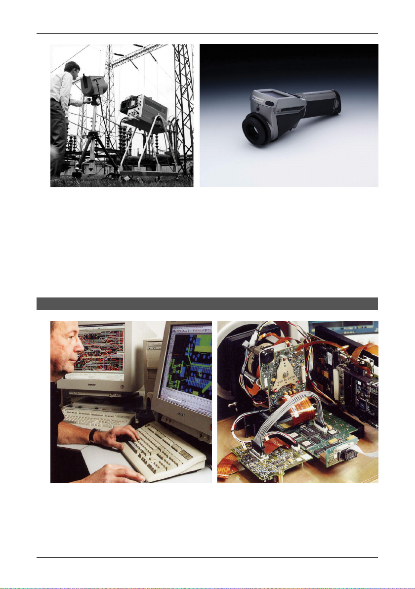
Figure 2.2 LEFT: FLIR Systems’ Thermovision® Model 661. The photo is taken on May 30th, 1969 at
the distribution plant near Beckomberga, in Stockholm, Sweden. The camera weighed approx. 25 kg
(55 lb), the oscilloscope 20 kg (44 lb), the tripod 15 kg (33 lb). The operator also needed a 220 VAC
generator set, and a 10 L (2.6 US gallon) jar with liquid nitrogen. To the left of the oscilloscope the
Polaroid attachment (6 kg/13 lb) can be seen. RIGHT: FLIR Systems’ ThermaCAM Model E2 from 2002
– weight: 0.7 kg (1.54 lb), including battery.
With this tradition of unparalleled technical excellence and innovative achievements, FLIR continues to develop new infrared products, educational venues and
applications expertise to meet the diverse demands of thermographers worldwide.
2.1.1 A few images from our facilities
10401303;1
Figure 2.3 LEFT: Development of system electronics; RIGHT: Testing of an FPA detector
4 Publ. No. 1 557 536 Rev. a35 – ENGLISH (EN) – January 20, 2004
10401403;1
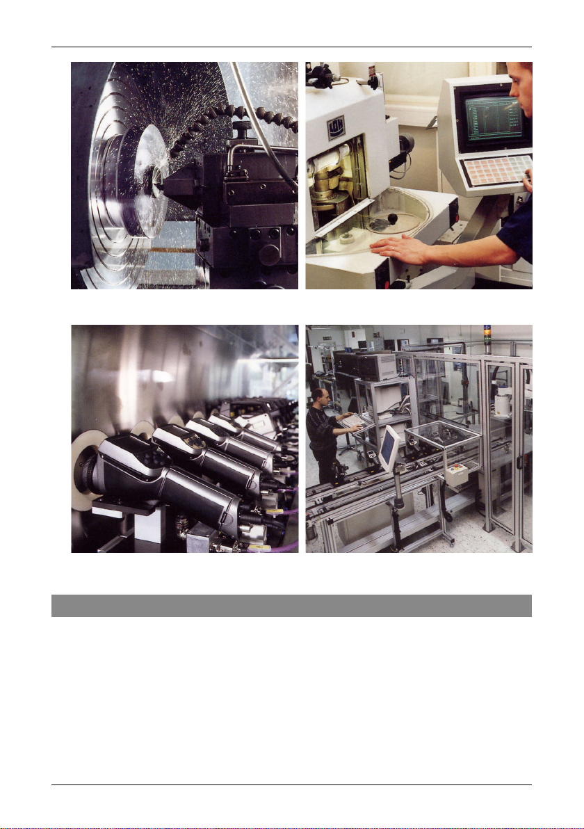
Figure 2.4 LEFT: Diamond turning machine; RIGHT: Lens polishing
10401503;1
2.2 – Comments & questions
Figure 2.5 LEFT: Testing of IR cameras in the climatic chamber; RIGHT: Robot for camera testing and
calibration
2.2 Comments & questions
FLIR Systems is committed to a policy of continuous development, and although
we have tested and verified the information in this manual to the best of our
ability, you may find that features and specifications have changed since the time
of printing. Please let us know about any errors you find, as well as your suggestions
for future editions, by sending an e-mail to:
documentation@flir.se
Publ. No. 1 557 536 Rev. a35 – ENGLISH (EN) – January 20, 2004 5

2.2 – Comments & questions
NOTE: Do not use this e-mail address for technical support questions. Technical support is handled
by FLIR Systems local sales offices.
6 Publ. No. 1 557 536 Rev. a35 – ENGLISH (EN) – January 20, 2004

3 Packing list
The ThermaCAM™ P20 and its accessories are delivered in a hard transport case
which typically contains the items below. On receipt of the transport case, inspect
all items and check them against the delivery note. Any damaged items must be
reported to the local FLIR Systems AB representative immediately.
QtyPart numberDescriptionNo.
1
2
3
4
5
6
7
8
9
10
11
12
NOTE: Please note the following:
■ The packing list is, to some degree, subject to customer configuration and may contain more or
less items.
■ FLIR Systems AB reserves the right to discontinue models, parts and accessories, and other items,
or change specifications at any time without prior notice.
SEE ALSO: For information about installing ThermaCAM Connect 3, see section 7 – Installation &
operation of ThermaCAM Connect 3 on page 18.
21 195 268Battery
11 909 820Adapter for CompactFlash card
11 195 267Battery charger
11 909 653CompactFlash card
11 195 317Lens cap
11 557 536Operator’s manual
11 909 528Power supply
1117 132Shoulder strap
11 195 850ThermaCAM Connect 3 CD
1Configuration-dependentThermaCAM™ P20
11 195 314USB cable
11 909 775CVBS video cable
Publ. No. 1 557 536 Rev. a35 – ENGLISH (EN) – January 20, 2004 7
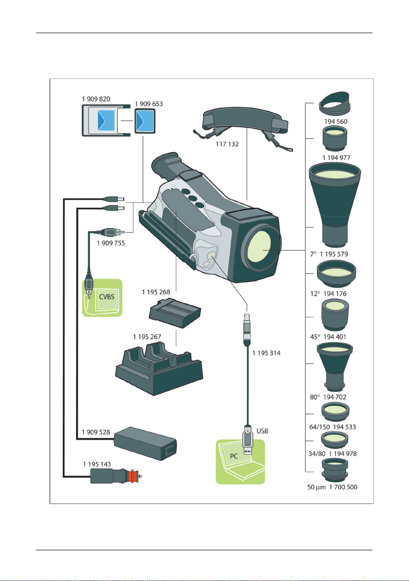
4 System overview
10397903;1
Figure 4.1 System overview
8 Publ. No. 1 557 536 Rev. a35 – ENGLISH (EN) – January 20, 2004

5 Connecting system components
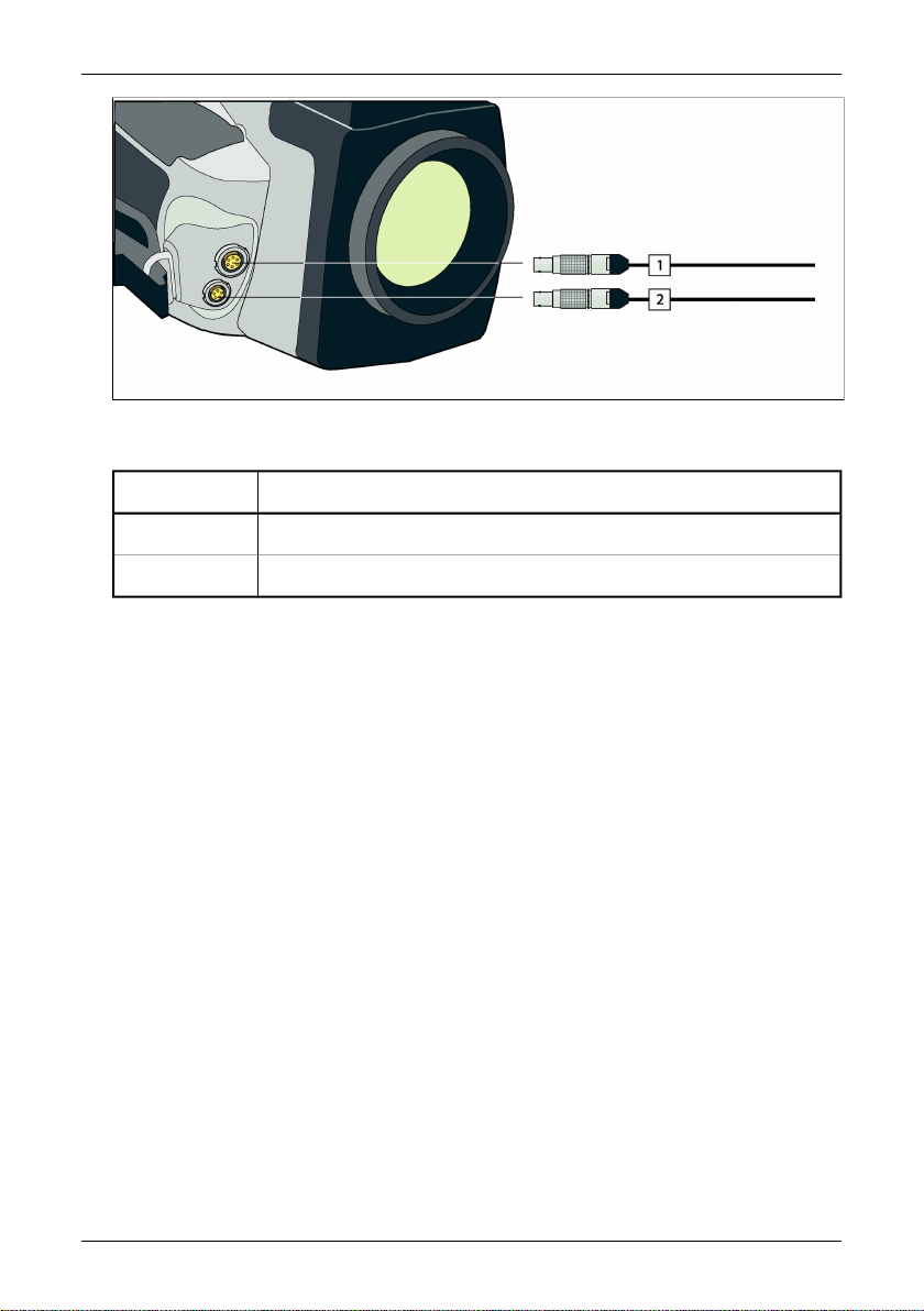
10438703;1
Figure 5.1 How to connect system components, 1: Rear connectors
Figure 5.2 Explanations of callouts
ExplanationCallout
1
2
3
4
5
Publ. No. 1 557 536 Rev. a35 – ENGLISH (EN) – January 20, 2004 9
Not available for this particular camera configuration.
CompactFlash card
Power supply cable
CVBS cable (i.e. composite video)
Remote control cable
NOTE: Depending on your camera configuration, a remote control may be an
extra option.
10438803;1
Figure 5.3 How to connect system components, 1: Front connectors
Figure 5.4 Explanations of callouts
ExplanationCallout
1
2
RS-232 / USB cable
Not available for this particular camera configuration.
10 Publ. No. 1 557 536 Rev. a35 – ENGLISH (EN) – January 20, 2004

6 Tutorials
6.1 Switching on & switching off the camera
ActionStep
1
2
3
SEE ALSO: For information about buttons, see section 8.2 – Keypad buttons & functions on page 36.
Insert a battery into the battery compartment.
NOTE: For information about inserting a battery, see section 6.6.5 – Inserting
& removing the battery on page 16.
Briefly press the green ON/OFF button to switch on the camera.
Press and hold down the green on/off button for a few seconds to switch off
the camera.
6.2 Working with images
6.2.1 Acquiring an image
ActionStep
1
2
3
4
6.2.2 Opening an image
Briefly press the green ON/OFF button to switch on the camera.
Point the camera at a warm object, like a face or a hand.
Press and hold down the A button for one second to adjust the focus.
Briefly press the A button to autoadjust the camera.
ActionStep
1
2
3
4
SEE ALSO: For more information about opening images, see section 9.2.2.1 – Open on page 41.
Publ. No. 1 557 536 Rev. a35 – ENGLISH (EN) – January 20, 2004 11
Press the joystick to display the horizontal menu bar.
Point to Open on the File menu and press the joystick.
Press the S button to move between the left and the right pane, and the joystick
to move up and down in the left and right pane.
To recall a selected image, press the joystick.

6.3 – Creating & changing an isotherm
6.2.3 Freezing & unfreezing an image
ActionStep
1
2
3
Press and hold down the A button for one second to adjust the focus.
Briefly press the A button to autoadjust the camera.
Briefly press the S button to freeze the image. To unfreeze the image, press
the S button once again.
6.2.4 Saving an image
ActionStep
1
2
3
SEE ALSO: For more information about saving images, see section 9.2.2.2 – Save on page 41. .
Press and hold down the A button for one second to adjust the focus.
Briefly press the A button to autoadjust the camera.
Do one of the following:
■
Press and hold down the S button for a few seconds to save the image
■
Point to Save on the File menu and press the joystick
6.3 Creating & changing an isotherm
ActionStep
1
2
Press the joystick to display the horizontal menu bar.
Point to Add isotherm on the Analysis menu and press the joystick. An isotherm
will now be added to your image. The isotherm levels will be displayed in the
result table in the top right corner of the screen.
You are now in edit mode and can change the isotherm levels by moving the
joystick up/down. To leave the edit mode, press the C button twice. You can
also leave the edit mode by holding down the joystick for a few seconds, which
will display a shortcut menu.
SEE ALSO: For more information about creating & changing an isotherm, see section 9.2.3.2 – Add
isotherm on page 42.
12 Publ. No. 1 557 536 Rev. a35 – ENGLISH (EN) – January 20, 2004

6.4 Changing level & span
6.4.1 Changing the level
ActionStep
6.4 – Changing level & span
1
2
3
4
NOTE: You can also change the level by pointing to Level/Span on the Image menu, and then change
the level by moving the joystick up/down.
SEE ALSO: For more information about level, see section 9.2.4.3 – Level/Span on page 46.
Press the joystick to display the horizontal menu bar.
If the camera is in continuous adjust mode, point to Manual adjust on the
Image menu and press the joystick.
Change the level by moving the joystick up/down. An arrow pointing upwards
or downwards will be displayed.
Press the joystick to leave level/span mode.
6.4.2 Changing the span
ActionStep
1
2
3
4
NOTE: You can also change the span by pointing to Level/Span on the Image menu, and then change
the span by moving the joystick left/right.
SEE ALSO: For more information about span, see section 9.2.4.3 – Level/Span on page 46.
Press the joystick to display the horizontal menu bar.
If the camera is in continuous adjust mode, point to Manual adjust on the
Image menu and press the joystick.
Change the span by moving the joystick left/right. Two arrows pointing away
from each other or towards each other will be displayed.
Press the joystick to leave level/span mode.
6.5 Changing system settings
6.5.1 Changing the language
ActionStep
1
2
3
Publ. No. 1 557 536 Rev. a35 – ENGLISH (EN) – January 20, 2004 13
Press the joystick to display the horizontal menu bar.
Point to Local settings on the Setup menu and press the joystick.
Move the joystick up/down to select Language.

6.5 – Changing system settings
ActionStep
4
5
Move the joystick left/right to change the language.
Press the joystick to confirm your changes and leave the dialog box.
NOTE: Changing the language will make the camera restart the camera
program. This will take a few seconds.
6.5.2 Changing the temperature unit
ActionStep
1
2
3
4
5
Press the joystick to display the horizontal menu bar.
Point to Local Settings on the Setup menu and press the joystick.
Move the joystick up/down to select Temp unit.
Move the joystick left/right to change the temperature unit.
Press the joystick to confirm your changes and leave the dialog box.
6.5.3 Changing the date format
ActionStep
1
2
3
Press the joystick to display the horizontal menu bar.
Point to Local Settings on the Setup menu and press the joystick.
Move the joystick up/down to select Date format.
4
5
Move the joystick left/right to change the date format.
Press the joystick to confirm your changes and leave the dialog box.
6.5.4 Changing the time format
ActionStep
1
2
3
4
5
Press the joystick to display the horizontal menu bar.
Point to Local Settings on the Setup menu and press the joystick.
Move the joystick up/down to select Time format.
Move the joystick left/right to change the time format.
Press the joystick to confirm your changes and leave the dialog box.
14 Publ. No. 1 557 536 Rev. a35 – ENGLISH (EN) – January 20, 2004
6.5.5 Changing date & time
ActionStep
6.6 – Working with the camera
1
2
3
4
5
Press the joystick to display the horizontal menu bar.
Point to Date/time on the Setup menu and press the joystick.
Move the joystick up/down to select year, month, day, minute and second.
Move the joystick left/right to change each parameter.
Press the joystick to confirm your changes and leave the dialog box.
6.6 Working with the camera
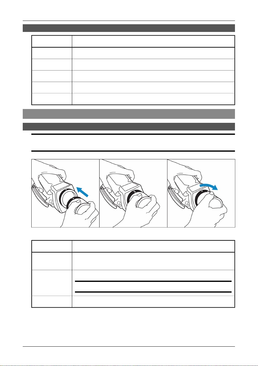
6.6.1 Mounting an additional lens
NOTE: Before trying to remove fingerprints or other marks on the lens elements, see section 12.2 –
Lenses on page 61.
10398403;2
Figure 6.1 Mounting an additional lens
ActionStep
1
2
3
Publ. No. 1 557 536 Rev. a35 – ENGLISH (EN) – January 20, 2004 15
Make sure the index mark on the IR lens is lined up with the index mark on the
camera.
Carefully push the lens into the lens recess.
NOTE: Do not use excessive force.
Rotate the lens 30° clock-wise.
6.6 – Working with the camera
6.6.2 Focusing the camera using autofocus
ActionStep
1
2
Press the green ON/OFF button to switch on the camera.
Press and hold down the A button for one second to adjust the focus. An indicator will be displayed on the left side of the screen when focusing.
6.6.3 Focusing the camera manually
ActionStep
1
2
Press the green ON/OFF button to switch on the camera.
Adjust the focus by moving the joystick up/down. An indicator will be displayed
on the left side of the screen when focusing.
6.6.4 Using the electronic zoom
ActionStep
1
2
Press the green ON/OFF button to switch on the camera.
Adjust the zoom factor by moving the joystick left/right. An indicator will be
displayed on the left side of the screen when zooming.
6.6.5 Inserting & removing the battery
NOTE: The camera is shipped with charged batteries. To increase battery life, the battery should be
fully discharged and charged a couple of times. You can do this by using the camera until the battery
is fully depleted.
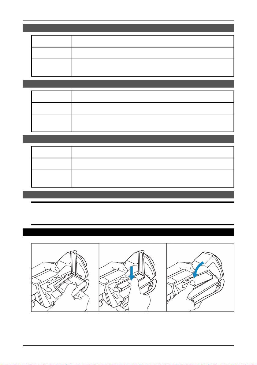
6.6.5.1 Inserting the battery
10398503;2
Figure 6.2 Inserting the battery
16 Publ. No. 1 557 536 Rev. a35 – ENGLISH (EN) – January 20, 2004
6.6 – Working with the camera
ActionStep
1
2
Open the lid of the battery compartment by pressing its locking mechanism.
Push the battery into the battery compartment until the battery release spring
locks.
3
Close the lid of the battery compartment.
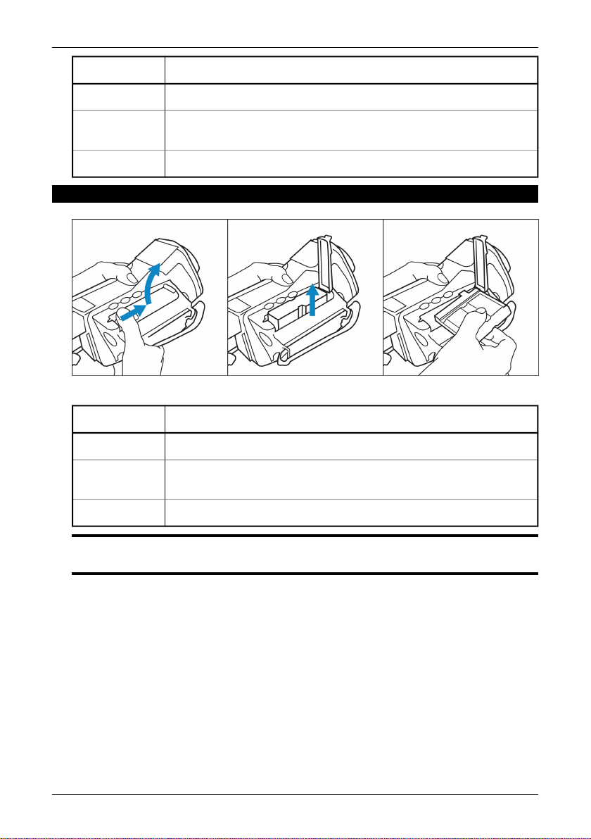
6.6.5.2 Removing the battery
10398603;2
Figure 6.3 Removing the battery
ActionStep
1
2
Open the lid of the battery compartment by pressing its locking mechanism.
The battery release spring will push out the battery from the battery compartment.
3
Close the lid of the battery compartment.
SEE ALSO: For more information about the battery system, see section 10 – Electrical power system
on page 55.
Publ. No. 1 557 536 Rev. a35 – ENGLISH (EN) – January 20, 2004 17

7 Installation & operation of
ThermaCAM Connect 3
7.1 Introduction
FLIR Systems AB’s software ThermaCAM Connect 3 lets you download images
from your infrared camera to your desktop or laptop computer.
7.2 Installation
NOTE: This installation tutorial applies to ThermaCAM Connect 3 only.
7.2.1 Software requirements
7.2.1.1 Camera
ThermaCAM Connect 3 will only work with these camera configurations:
P/S series cameras: boot2 version 2.4.2.1 (or higher)
■
P/S series cameras: appl version 2.4.4.1 (or higher)
■
To check the version of boot2/appl, select Setup → Camera Info in the camera.
Make sure the version number of the module ‘boot2'/'appl’ is as stated above.
7.2.1.2 PC
Serial communication (RS-232) between PC and camera is supported on the following operating systems:
Windows 98 Second Edition
■
Windows Me
■
Windows NT 4, Service Pack 6
■
Windows 2000
■
Windows XP
■
USB and connections between PC and camera is supported on the following operating systems:
Windows 98 Second Edition
■
Windows Me
■
Windows 2000
■
Windows XP
■
NOTE: Before you install the application, please close all other programs on the computer. Make sure
ThermaCAM Connect 3 is installed before connecting the camera to the USB or port.
18 Publ. No. 1 557 536 Rev. a35 – ENGLISH (EN) – January 20, 2004
 Loading...