

Page 1

The information contained in this document pertains to a dual use product controlled for export by the Export Administration
Regulations (EAR). Diversion contrary to US law is prohibited. US Department of Commerce authorization is not required prior to
export or transfer to foreign persons or parties unless otherwise prohibited.
i
Tau SWIR ISC1202
User’s Guide
Document Number: 102-2009-45
Revision 102
Issue Date: October 2018
Page 2

The information contained in this document pertains to a dual use product controlled for export by the Export Administration
Regulations (EAR). Diversion contrary to US law is prohibited. US Department of Commerce authorization is not required prior to
export or transfer to foreign persons or parties unless otherwise prohibited.
ii
Table of Contents
1.0 Scope .............................................................................................................. vi
2.0 Resources ......................................................................................................... 7
FLIR Reference Documents.......................................................................................................... 7
3.0 Unpacking the Camera .................................................................................. 7
4.0 Standard Camera Kit ..................................................................................... 8
Electrical Interface ........................................................................................................................ 8
Main Connector .................................................................................................................................... 8
TEC Connector ................................................................................................................................... 13
TEC Power Through Accessory Boards ............................................................................................. 14
Mechanical Interface ................................................................................................................... 15
Optical Interface .......................................................................................................................... 16
5.0 Optional Accessories ....................................................................................16
VPC Module Accessory .............................................................................................................. 16
Installation ........................................................................................................................................... 18
Camera Link Module Accessory ................................................................................................. 19
Installation ........................................................................................................................................... 20
6.0 Connecting to the Camera ...........................................................................21
Physical Connection .................................................................................................................... 21
FLIR Camera Controller GUI ..................................................................................................... 22
FLIR Camera Controller Software Interface............................................................................... 24
Troubleshooting the FLIR Camera Controller GUI .................................................................... 27
7.0 Operation of the FLIR Camera Controller GUI .......................................29
Menu Bar .................................................................................................................................... 29
Calibration Tab ........................................................................................................................... 31
Optimization Tab ........................................................................................................................ 35
AGC Modes: ....................................................................................................................................... 35
Linear Parameters: .............................................................................................................................. 38
Automatic Parameters: ........................................................................................................................ 38
Enhancements: .................................................................................................................................... 39
Page 3

The information contained in this document pertains to a dual use product controlled for export by the Export Administration
Regulations (EAR). Diversion contrary to US law is prohibited. US Department of Commerce authorization is not required prior to
export or transfer to foreign persons or parties unless otherwise prohibited.
iii
AGC ROI: ........................................................................................................................................... 39
Window Editor .................................................................................................................................... 40
AGC ROI Coordinate Values ............................................................................................................. 40
Digital Zoom: ...................................................................................................................................... 40
Orientation: ......................................................................................................................................... 40
Polarity / Palette: ................................................................................................................................. 41
Auto-Exposure Enable: ....................................................................................................................... 42
Save Settings ....................................................................................................................................... 42
Factory Defaults .................................................................................................................................. 42
Reset Camera ...................................................................................................................................... 42
Utilities Tab ................................................................................................................................ 43
Camera Link Configuration ................................................................................................................ 43
Camera Updates .................................................................................................................................. 44
External Sync ...................................................................................................................................... 45
Test Pattern ......................................................................................................................................... 47
TEC Control ........................................................................................................................................ 47
Lens Control ........................................................................................................................................ 47
Save Settings ....................................................................................................................................... 47
Factory Defaults .................................................................................................................................. 48
Reset Camera ...................................................................................................................................... 48
Debug .......................................................................................................................................... 49
8.0 Appendix – Extraordinary Conditions .......................................................50
Disassmbly .................................................................................................................................. 50
Cleaning the VPA Window......................................................................................................... 50
External Conditions .................................................................................................................... 50
Page 4

The information contained in this document pertains to a dual use product controlled for export by the Export Administration
Regulations (EAR). Diversion contrary to US law is prohibited. US Department of Commerce authorization is not required prior to
export or transfer to foreign persons or parties unless otherwise prohibited.
iv
Table of Figures
FIGURE 1. TAU SWIR CAMERA –HIROSE CONNECTOR ................................................................................... 8
FIGURE 2. PINS ON TAU SWIR HIROSE CONNECTOR ................................................................ ....................... 9
FIGURE 3. DETAILED ILLUSTRATION OF TEC POWER CONNECTOR ......................................................... 13
FIGURE 4. TEC POWER CONNECTOR PIN ASSIGNMENTS ............................................................................. 13
FIGURE 5. TEC WIRES ............................................................................................................................................ 14
FIGURE 6. OPTIONAL ¼-20 MOUNT ACCESSORY ............................................................................................ 15
FIGURE 7. FRONT-FACE C-MOUNT ADAPTOR .................................................................................................. 16
FIGURE 8. TAU SWIR CAMERA WITH VPC MODULE ...................................................................................... 17
FIGURE 9. VPC MODULE ACCESSORY KIT ....................................................................................................... 18
FIGURE 11. CAMERA LINK MODULE (SHOWN INSTALLED ON A TAU SWIR CAMERA) ........................ 19
FIGURE 12. CAMERA LINK MODULE ACCESSORY KIT ................................................................................. 20
FIGURE 13. CAMERA LINK MODULE INSTALLATION ................................................................................... 20
FIGURE 14. BNC TO RCA ADAPTOR ................................................................................................................... 21
FIGURE 15. DEVICE MANAGER SHOWING PROPER DRIVER INSTALLATION .......................................... 23
FIGURE 16. SELECT CAMERA MANAGER ......................................................................................................... 24
FIGURE 17. FLIR CAMERA CONTROLLER GUI STATUS TAB – NOT CONNECTED ................................... 25
FIGURE 18. FLIR CAMERA CONTROLLER GUI CONNECTION WINDOW PART 1...................................... 26
FIGURE 19. FLIR CAMERA CONTROLLER GUI CONNECTION WINDOW PART 2...................................... 26
FIGURE 20. CAMERA TYPE SELECTION ............................................................................................................ 27
FIGURE 21. FLIR CAMERA CONTROLLER GUI STATUS TAB – CONNECTED ............................................ 27
FIGURE 22. FLIR CAMERA CONTROLLER ERROR MESSAGE ....................................................................... 27
FIGURE 23. FLIR CAMERA CONTROLLER GUI – MENU BAR ........................................................................ 29
FIGURE 24. HELP -- ABOUT CAMERA CONTROLLER ..................................................................................... 30
FIGURE 25. FLIR CAMERA CONTROLLER GUI – STATUS TAB ..................................................................... 31
FIGURE 26. FLIR CAMERA CONTROLLER GUI -- OPTIMIZATION TAB ....................................................... 35
FIGURE 27. LOOK-UP TABLE OPTIONS (AS SEEN WITH TEST PATTERN ENABLED) .............................. 41
FIGURE 28. FLIR CAMERA CONTROLLER GUI -- VIDEO TAB ................................................................ ....... 43
FIGURE 29. IMPERX FRAMELINK EXPRESS SOFTWARE – CAMERA PARAMETERS WINDOW ............. 44
FIGURE 30. INTEGRATION PRIORITY MODE SYNCHRONIZATION ............................................................. 46
FIGURE 31. READOUT PRIORITY MODE SYNCHRONIZATION ..................................................................... 47
FIGURE 32. FLIR CAMERA CONTROLLER – DEBUG TAB .............................................................................. 49
Page 5

The information contained in this document pertains to a dual use product controlled for export by the Export Administration
Regulations (EAR). Diversion contrary to US law is prohibited. US Department of Commerce authorization is not required prior to
export or transfer to foreign persons or parties unless otherwise prohibited.
v
Revision History
Version
Date
Comments
100
December 2016
Initial release
101
February 2018
Added detail to descriptions
102
October 2018
Updated controls for TEC table
List of Abbreviations
Abbreviation/
Acronym
Components
ACE
Actinve Contrast Enhancement
AGC
Automatic Gain Control
CDS
Correlated Double Sampling
DDE
Digital Detail Enhancement
ESD
Electrostatic Damage
FFC
Flat Field Calibration (or Correction)
FOV
Field of View
FPA
Focal Plane Array
FPS
Frames Per Second
GUI
Graphical User Interface
I/O
Input / Output
ICD
Interface Control Drawing / Document
IDD
Interface Description Drawing / Document
InGaAs
Indium Galium Arsenide
ISC1202
Indigo Systems Corporation, February 2012
LACE
Local Area Contrast Enhancement
LUT
Look-Up Table
NTSC
National Television System Committee
NUC
Non Uniformity Correction
OSD
On Screen Display
PAL
Phase Alternating Line
Page 6

The information contained in this document pertains to a dual use product controlled for export by the Export Administration
Regulations (EAR). Diversion contrary to US law is prohibited. US Department of Commerce authorization is not required prior to
export or transfer to foreign persons or parties unless otherwise prohibited.
vi
Abbreviation/
Acronym
Components
REACH
Registration, Evaluation, Authorisation and Restriction of Chemicals
RoHS
Reduction of Hazardous Substances
ROI
Region of Interest
ROIC
Read Out Integrated Circuit
SIC-200
Silicon Inspection XX
SWIR
Short Wave Infrared
SSO
Smart Scene Optimization
TBD
To Be Determined
TEC
Thermo Electric Cooler
URL
Uniform Resource Locator
USB
Universal Serial Bus
VPA
Vacuum Package Assembly
Page 7

Page 7
The information contained in this document pertains to a dual use product controlled for export by the Export Administration
Regulations (EAR). Diversion contrary to US law is prohibited. US Department of Commerce authorization is not required prior to
export or transfer to foreign persons or parties unless otherwise prohibited.
1.0 Scope
Tau ™ SWIR is a miniature, 38mm×38mm×47mm, short wave infrared (SWIR) imaging core from FLIR
Systems, built around FLIR’s ISC1202 InGaAs SWIR sensor. This sensor provides high sensitivity from
0.9 to 1.7μm, low dark current, temperature stabilization and on chip (in-pixel) correlated double sampling
(CDS) for noise reduction, CDS fold-over protection (prevents “black sun effect”), anti-blooming (low gain
only), snapshot integration, 640 × 512 resolution with a 15μm pixel pitch running at 60 frames per second.
FLIR’s proprietary image processing algorithms start with 14-bit digital imagery and result in high-quality,
analog video or 8-bit digital imagery in both low light conditions and full daylight. Frame rates may be
adjusted from a minimum of 1fps to a maximum of 60fps for a full frame image. A preset 2X window of
the central 320 × 256 pixels may be selected allowing for a frame rate of up to 120fps. An external sync
mode allows integration with other camera systems, SWIR illuminators or pulsed lasers, synchronizing the
integration period of the camera with the external system.
There are three sensor gain modes providing increasing sensitivity, Low, Mid or High. Low gain is
appropriate for well illuminated, wide dynamic range scenes while each step up in sensitivity allows
imaging under lower SWIR illumination levels with an accompanying decrease in the dynamic range that
can be imaged. Within each gain mode, the integration period may be adjusted from as little as 10μs to as
high as the frame period. Response of the 14-bit digital imagery increases linearly with increasing
integration period.
FLIR’s built in Auto-Exposure algorithm allows automatic, smooth transitions of integration period (tint)
based on scene content to maximize image quality and detail without user intervention.The camera includes
FLIR’s advanced Non-Uniformity Correction (NUC), in-camera nonresponsive pixel replacement and
Automatic Gain Control (AGC) algorithms. The Tau SWIR comes standard with a C-mount lens adapter
installed. This may be removed allowing for custom lens mounts.
This User’s Guide includes quick-start information for the Tau SWIR, as well as detailed descriptions of
functions and adjustments for the camera that can be performed using FLIR’s Tau SWIR Camera Controller
GUI.
2.0 Resources
FLIR Reference Documents
Document Number
Document Title
102-2009-42
Tau SWIR 1202 Software IDD
102-2009-40
Tau SWIR 1202 Product Specification
102-2009-44
Tau SWIR Mechanical IDD
3.0 Unpacking the Camera
Page 8
Page 8
The information contained in this document pertains to a dual use product controlled for export by the Export Administration
Regulations (EAR). Diversion contrary to US law is prohibited. US Department of Commerce authorization is not required prior to
export or transfer to foreign persons or parties unless otherwise prohibited.
When unpacking the camera, please heed customary electrostatic-discharge (ESD) sensitive device
precautions including static-safe work station and proper grounding. The camera is placed in a conductive
anti-static bag to protect from electrostatic-discharge damage and safely packaged to prevent damage during
shipping.
4.0 Standard Camera Kit
Components that come standard with the Tau SWIR camera are:
1. Camera body (includes standard Tau backshell, C-Mount Adapter installed)
2. 2-Wire, 12” lead for TEC power (shown in Figure 5)
3. Black Cap to cover C-Mount
Electrical Interface
Main Connector
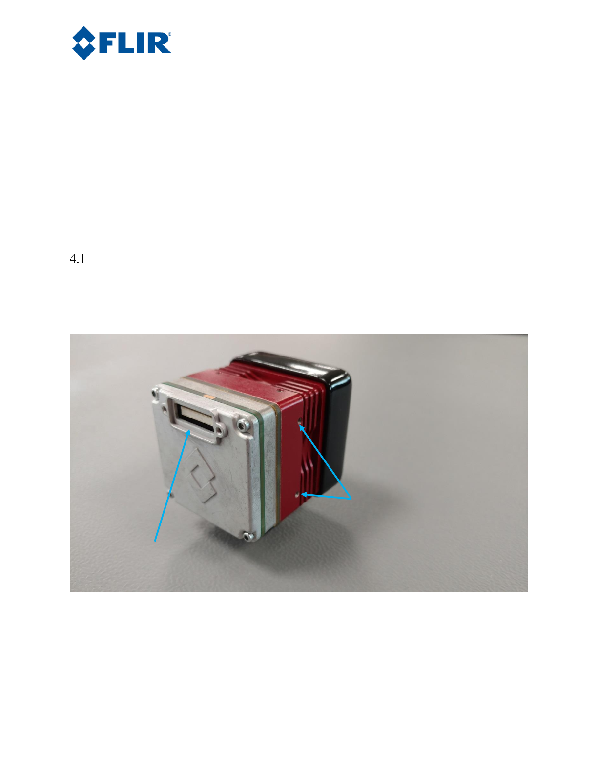
Communication, video, and camera power are all accommodated through the Hirose 50-pin connector
shown in Figure 1 and Figure 2. Pin designations are described in Table 1, Table 2, and Table 3.
Figure 1. Tau SWIR Camera –Hirose Connector
M2x0.4, 4mm deep mounting
holes, 24mm separation, 3 sides.
high-density 50-pin connector:
Hirose #DF12-50DS-0.5V(86)
Page 9

Page 9
The information contained in this document pertains to a dual use product controlled for export by the Export Administration
Regulations (EAR). Diversion contrary to US law is prohibited. US Department of Commerce authorization is not required prior to
export or transfer to foreign persons or parties unless otherwise prohibited.
Figure 2. Pins on Tau SWIR Hirose Connector
Page 10

Page 10
The information contained in this document pertains to a dual use product controlled for export by the Export Administration
Regulations (EAR). Diversion contrary to US law is prohibited. US Department of Commerce authorization is not required prior to
export or transfer to foreign persons or parties unless otherwise prohibited.
Table 1. Tau SWIR Pin-Out, Hirose Connector Mode (2) CMOS 14-bit (default)
Pin #
Signal Name
Pin #
Signal Name
1
COMM_TX (RS232_TX_OUT)
2
COMM_RX (RS232_RX_IN)
3
CMOS LINE_VALID_OUT
4
CMOS FRAME_VALID_OUT
5
DGND
6
DGND
7
CAMLINK_CLK [P]
8
CAMLINK_CLK [N]
9
CAMLINK_DATA [0P]
10
CAMLINK_DATA [0N]
11
CAMLINK_DATA [1P]
12
CAMLINK_DATA [1N]
13
CAMLINK_DATA [2P]
14
CAMLINK_DATA [2N]
15
CAMLINK_DATA [3P]
16
CAMLINK_DATA [3N]
17
DGND
18
DGND
19
DISCRETE IO REG [0]
20
CMOS DATA_OUT [13]
21
EXTERNAL_SYNC
22
CMOS DATA_OUT [12]
23
CMOS DATA_OUT [11]
24
CMOS DATA_OUT [10]
25
CMOS DATA_OUT [9]
26
CMOS DATA_OUT [8]
27
DGND
28
DGND
29
CMOS DATA_OUT [7]
30
CMOS DATA_OUT [6]
31
CMOS DATA_OUT [5]
32
CMOS DATA_OUT [4]
33
CMOS DATA_OUT [3]
34
CMOS DATA_OUT [2]
35
CMOS DATA_OUT [1]
36
CMOS DATA_OUT [0]
37
DGND
38
DGND
39
CMOS CLOCK_OUT
40 Z 41
DGND
42
DGND
43
VID_OUT_H
44
VID_OUT_L
45
DGND
46
n/c
47
MAIN_PWR_RTN
48
MAIN_PWR
49
MAIN_PWR_RTN
50
MAIN_PWR
Page 11

Page 11
The information contained in this document pertains to a dual use product controlled for export by the Export Administration
Regulations (EAR). Diversion contrary to US law is prohibited. US Department of Commerce authorization is not required prior to
export or transfer to foreign persons or parties unless otherwise prohibited.
Table 2. Pinout Hirose 50-Pin Connector, Output Mode (3) CMOS 8-bit
Pin #
Signal Name
Pin #
Signal Name
1
COMM_TX (RS232_TX_OUT)
2
COMM_RX (RS232_RX_IN)
3
LINE_VALID_OUT
4
FRAME_VALID_OUT
5
DGND
6
DGND
7
CAMLINK_CLK [P]
8
CAMLINK_CLK [N]
9
CAMLINK_DATA [0P]
10
CAMLINK_DATA [0N]
11
CAMLINK_DATA [1P]
12
CAMLINK_DATA [1N]
13
CAMLINK_DATA [2P]
14
CAMLINK_DATA [2N]
15
CAMLINK_DATA [3P]
16
CAMLINK_DATA [3N]
17
DGND
18
DGND
19
DISCRETE IO REG [0]
20
DISCRETE IO REG [1]
21
EXTERNAL_SYNC
22
(XP 12) Z
23
DISCRETE IO REG [2]
24
DISCRETE IO REG [3]
25
DISCRETE IO REG [4]
26
DISCRETE IO REG [5]
27
DGND
28
DGND
29
CMOS DATA_OUT [7]
30
CMOS DATA_OUT [6]
31
CMOS DATA_OUT [5]
32
CMOS DATA_OUT [4]
33
CMOS DATA_OUT [3]
34
CMOS DATA_OUT [2]
35
CMOS DATA_OUT [1]
36
CMOS DATA_OUT [0]
37
DGND
38
DGND
39
CLOCK_OUT
40
Z
41
DGND
42
DGND
43
VID_OUT_H
44
VID_OUT_L
45
DGND
46
n/c
47
MAIN_PWR_RTN
48
MAIN_PWR
49
MAIN_PWR_RTN
50
MAIN_PWR
Page 12

Page 12
The information contained in this document pertains to a dual use product controlled for export by the Export Administration
Regulations (EAR). Diversion contrary to US law is prohibited. US Department of Commerce authorization is not required prior to
export or transfer to foreign persons or parties unless otherwise prohibited.
Table 3. Pinout Hirose 50-pin Connector, Output Mode (1), BT.656
Pin #
Signal Name
Pin #
Signal Name
1
COMM_TX (RS232_TX_OUT)
2
COMM_RX (RS232_RX_IN)
3
DISCRETE IO REG [6]
4
DISCRETE IO REG [7]
5
DGND
6
DGND
7
CAMLINK_CLK [P]
8
CAMLINK_CLK [N]
9
CAMLINK_DATA [0P]
10
CAMLINK_DATA [0N]
11
CAMLINK_DATA [1P]
12
CAMLINK_DATA [1N]
13
CAMLINK_DATA [2P]
14
CAMLINK_DATA [2N]
15
CAMLINK_DATA [3P]
16
CAMLINK_DATA [3N]
17
DGND
18
DGND
19
DISCRETE IO REG [0]
20
DISCRETE IO REG [1]
21
EXTERNAL_SYNC
22
(XP 12) Z
23
DISCRETE IO REG [2]
24
DISCRETE IO REG [3]
25
DISCRETE IO REG [4]
26
DISCRETE IO REG [5]
27
DGND
28
DGND
29
BT656 DATA_OUT [7]
30
BT656 DATA_OUT [6]
31
BT656 DATA_OUT [5]
32
BT656 DATA_OUT [4]
33
BT656 DATA_OUT [3]
34
BT656 DATA_OUT [2]
35
BT656 DATA_OUT [1]
36
BT656 DATA_OUT [0]
37
DGND
38
DGND
39
CLOCK_OUT BT656 (27Mhz)
40
Z
41
DGND
42
DGND
43
VID_OUT_H
44
VID_OUT_L
45
DGND
46
n/c
47
MAIN_PWR_RTN
48
MAIN_PWR
49
MAIN_PWR_RTN
50
MAIN_PWR
Page 13
Page 13
The information contained in this document pertains to a dual use product controlled for export by the Export Administration
Regulations (EAR). Diversion contrary to US law is prohibited. US Department of Commerce authorization is not required prior to
export or transfer to foreign persons or parties unless otherwise prohibited.
TEC Connector
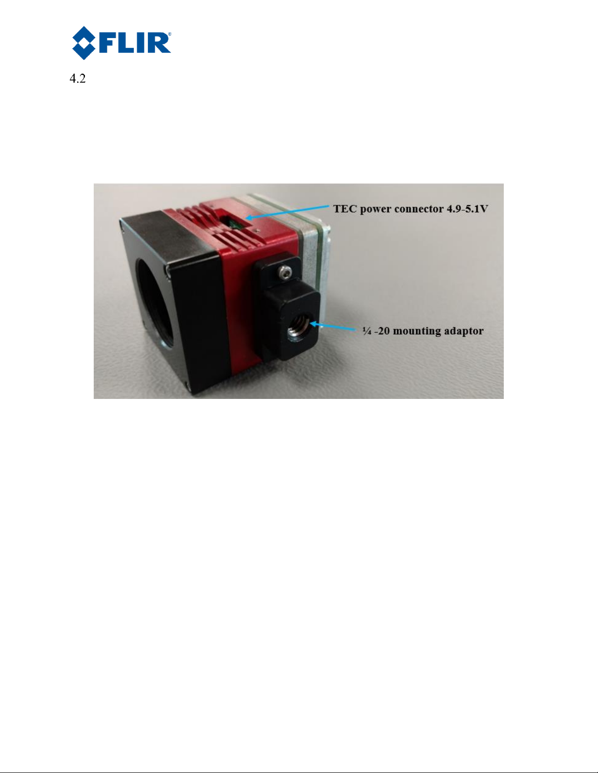
On one side of the camera housing there is a Molex connector that provides power for the thermo-electric
cooler (TEC). The TEC requires 4.9-5.5VDC input. While actual power consumption will vary with the
ambient and mounting environment, peak power for this connection is limited to 2.5W. Commonly, this
connector requires 0.3W at room ambient temperatures with the camera mounted on a tripod.
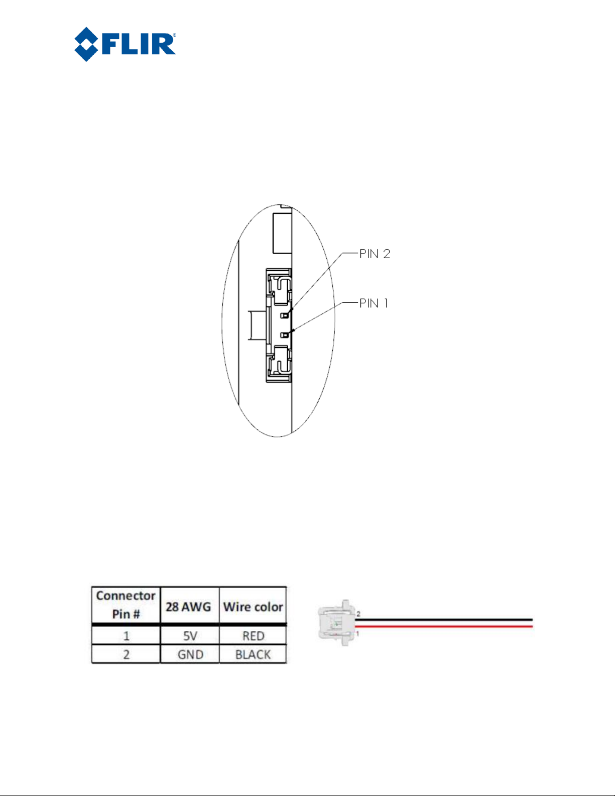
Included in the standard camera kit is a matching TEC power cable (FLIR PN 308-0268-00) terminated
at one end with a Molex Pico-Lock 2-pin connector. See Figure 5. This connector is keyed to prevent
connecting a reversed voltage to the TEC. The wires are black and red. The red is for a +5V supply and
the black is for the return or ground.
Figure 3. Detailed illustration of TEC power connector
Note: If, for any reason, the TEC power cable must be removed, the Molex Pico-Lock connector must be
pinched on both ends to disengage the locking mechanism. Once unlocked, gently pull out and slightly
forward (toward the front of the camera), ensuring the connector does not get hung up on the camera
body. Apply the minimum force necessary to remove the cable from the connector. Use caution as to not
pull the wires out of the connector body.
Figure 4. TEC Power Connector Pin Assignments
Page 14
Page 14
The information contained in this document pertains to a dual use product controlled for export by the Export Administration
Regulations (EAR). Diversion contrary to US law is prohibited. US Department of Commerce authorization is not required prior to
export or transfer to foreign persons or parties unless otherwise prohibited.
TEC Power Through Accessory Boards
When using either the VPC or Camera Link Adaptor accessory boards, power may be supplied to the
TEC Power connector via a cable from the accessory board. See Section 5.0 for a description of these
accessory boards. Once connected, a cover plate is installed over the cable and TEC power connector
port on the side of the camera. In this configuration both camera power and TEC power are supplied
through the USB connector on the accessory board. With either of these two accessory boards a USB
cable with a second power input is provided to handle higher than ½ amp current normally supplied
through USB from a computer.
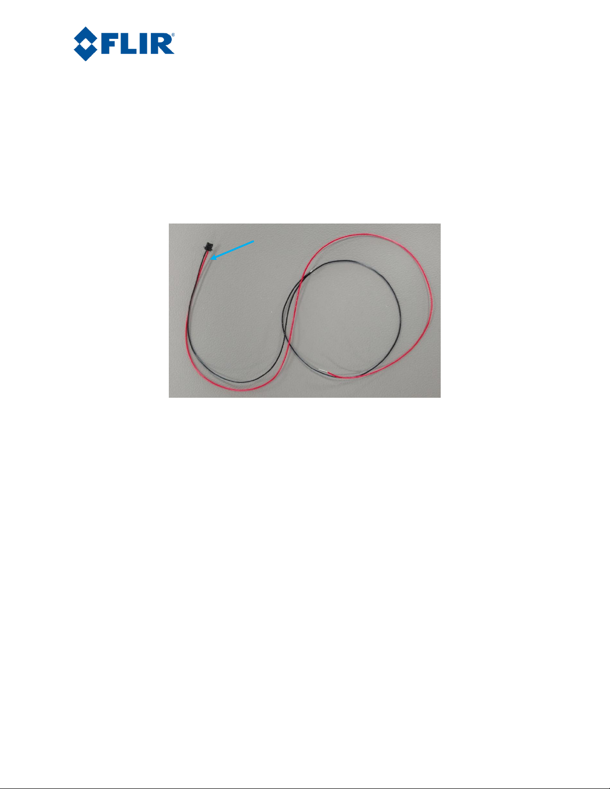
Figure 5. TEC wires
TEC power connector
Page 15
Page 15
The information contained in this document pertains to a dual use product controlled for export by the Export Administration
Regulations (EAR). Diversion contrary to US law is prohibited. US Department of Commerce authorization is not required prior to
export or transfer to foreign persons or parties unless otherwise prohibited.
Mechanical Interface
Mechanically mounting the camera can be accomplished by utilizing the M2.0 x 0.4 mounting holes
located on the top, bottom and left side of the camera. Each pair of holes are 4mm deep and have a 24mm
separation.
Alternatively, an optional ¼ x 20 mounting accessory (FLIR part number 261‐2071‐00) can be purchased
that utilizes one of the the three M2.0 x 0.4 hole pairs. See Figure 6.
Figure 6. Optional ¼-20 Mount Accessory
Page 16
Page 16
The information contained in this document pertains to a dual use product controlled for export by the Export Administration
Regulations (EAR). Diversion contrary to US law is prohibited. US Department of Commerce authorization is not required prior to
export or transfer to foreign persons or parties unless otherwise prohibited.
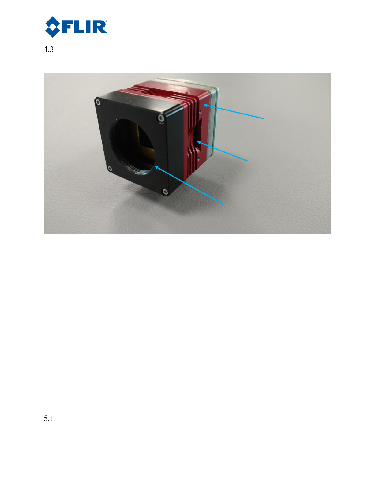
Optical Interface
The standard Tau SWIR camera kit comes with a C-mount optical adaptor, as shown in Figure 7.
Figure 7. Front-Face C-Mount Adaptor
If the C-mount interface is not needed, it can be removed by unscrewing the four M1.6 mounting screws
using an M1.5 allen head wrench. Further details on the optical interface can be found in the Mechanical
IDD document. Use extreme caution when working with the optics to prevent contamination of the VPA
window. If cleaning becomes necessary, see Section 8.2 for instructions.
5.0 Optional Accessories
The Tau SWIR Camera can be used with either the Tau SWIR VPC Module Accessory (FLIR PN 4210059-00) or the Tau SWIR Camera Link Module Accessory (FLIR PN 421-0058-00) for simple desktop
operation. These accessories provide an easy way to evaluate the camera core and access analog and, in
the case of the Camera Link Module, digital video during development. To help simplify mechanical
mounting of the Tau SWIR camera, it can be used with the ¼ 20 Mount accessory (261‐2071‐00).
When using either the VPC or Camera Link Adaptor accessory boards, power may be supplied to the
TEC power connector via a cable from the accessory board. A cover plate is installed (see Figure 8) over
the cable and TEC power connector port on the side of the camera. In this configuration both camera
power and TEC power are supplied through the USB connector on the accessory board.
VPC Module Accessory
C-Mount Adaptor
TEC Power Connector
Camera Body
Page 17

Page 17
The information contained in this document pertains to a dual use product controlled for export by the Export Administration
Regulations (EAR). Diversion contrary to US law is prohibited. US Department of Commerce authorization is not required prior to
export or transfer to foreign persons or parties unless otherwise prohibited.
The VPC module accessory kit includes a special USB-A (2-headed) to USB-mini B power and serial
communication cable, USB power supply, MCX-to-BNC analog video cable, TEC Power Cover Plate,
module mounting screws, and cover plate mounting screws. This module differs from the standard Tau
(uncooloed) camera VPC modle in that it has an additional VPC-to-TEC cable. Due to the fact that
standard USB ports on computers typically cannot supply enough current to run the TauSWIR camera
and TEC, both USB-A connectors on the USB cable must be plugged into a power source when this
VPC-to-TEC cable is connected to the camera.
Figure 8. Tau SWIR camera with VPC module
Analog video out
USB mini,
communication
and power
TEC power cover plate
Page 18

Page 18
The information contained in this document pertains to a dual use product controlled for export by the Export Administration
Regulations (EAR). Diversion contrary to US law is prohibited. US Department of Commerce authorization is not required prior to
export or transfer to foreign persons or parties unless otherwise prohibited.
VPC Installation
The VPC module plugs into the Hirose connector on the back of the Tau SWIR camera, as shown in
Figure 8. Use the two M1.6 x 0.35 x 8mm screws included in the kit to secure the module to the camera.
Plug the TEC cable into the TEC power connector on the side of the camera. Install the TEC power cover
plate using the supplied screws.
Figure 9. VPC Module Accessory Kit
Page 19

Page 19
The information contained in this document pertains to a dual use product controlled for export by the Export Administration
Regulations (EAR). Diversion contrary to US law is prohibited. US Department of Commerce authorization is not required prior to
export or transfer to foreign persons or parties unless otherwise prohibited.
Camera Link Module Accessory
The Camera Link module is an expansion board for FLIR cameras that matches the functionality of the
VPC Module and adds the ability to access digital data via Camera Link connection. The Camera Link
module takes CMOS-type digital data from the camera and converts it to Camera Link. In order to use a
Camera Link module for acquisition of data, first enable the digital data output using the FLIR Camera
Controller GUI. The red/black wires connect to the TEC board. The black and green wires are connected
to the external synchronization signal in the camera. This accessory does not include a Camera Link
cable, frame grabber, or capture software.
Figure 10. Camera Link Module (shown installed on a Tau SWIR camera)
Page 20

Page 20
The information contained in this document pertains to a dual use product controlled for export by the Export Administration
Regulations (EAR). Diversion contrary to US law is prohibited. US Department of Commerce authorization is not required prior to
export or transfer to foreign persons or parties unless otherwise prohibited.
Figure 11. Camera Link Module Accessory Kit
Camera Link Installation
The Camera Link Module plugs into the Hirose connector on the back of the Tau SWIR camera, as shown
in.Figure 10. Prior to installing the two M1.6 x 0.35 x 20mm screws, the two mini spacers must be
slipped in between the module and the back cover of the camera, as shown in Figure 12.
Figure 12. Camera Link Module Installation
Plug the TEC cable into the TEC power connector on the side of the camera, ensureing the locking
mechanism engages. Install the TEC power cover plate using the supplied screws. If, for any reason, the
TEC power connector must be removed, the Molex Pico-Lock connector must be pinched on both ends to
disengagy the locking mechanism. Once unlocked, gently pull out and slightly forward (toward the front
of the camera), ensuring the connector does not get hung up on the camera body. Apply the minimum
force necessary to remove the cable from the connector. Use caution as to not pull the wires out of the
connector body.
Page 21

Page 21
The information contained in this document pertains to a dual use product controlled for export by the Export Administration
Regulations (EAR). Diversion contrary to US law is prohibited. US Department of Commerce authorization is not required prior to
export or transfer to foreign persons or parties unless otherwise prohibited.
6.0 Connecting to the Camera
This section describes installation of necessary software, physical camera connections, and software
connection to the camera.
Physical Connection
This section describes physical connections to the camera and assumes that either the VPC or Camera Link
Accessory Module is being used with the camera. For connections not involving either of these FLIR
accessories, please see Section 4.1 for a description of the Hirose connector interface.
1. Plug the accessory (VPC or Camera Link) expansion board directly into the 50-pin Hirose
connector on the rear of the camera. Use the included hardware to secure the expansion board to
the camera. These will insert on either side of the 50-pin connector. The VPC module uses M1.6 ×
0.35 × 8 mm screws (see Section 5.1 on VPC installation) and the Camera Link module uses M1.6
× 0.35 × 8 mm screws. Using longer screws could damage the camera. The Camera Link module
also requires the installation of two M1.6 x 0.35 x 20mm screws. Make sure to install the two
spacers between the back cover of the camera and the Camera Link module (see section 5.2 on
Camera Link installation). An M1.5 allen head wrench will be required for tightening the screws.
2. Connect the analog video cable to the VPC or Camera Link Module. There is an MCX mini coaxial
connector on the back of each accessory. The opposite end of the cable has a standard BNC
connector. Connect this to the video input of an analog monitor. It may be necessary to use a BNC
Female to Phono Plug (RCA) adaptor (Figure 13) included in the accessory kit, which allows the
camera to be connected to a standard yellow RCA video input on a monitor. The Tau SWIR camera
core provides either NTSC or PAL compatible composite video output, selectable in the software
GUI or SDK.
Note: For best transmission of the analog video channel, a coaxial cable with 75 ohm
characteristic impedance, similar to what is included in the VPC and Camera Link module kits, is
required. The analog output is current mode and a 75 Ohm termination is required. This
termination is present in most display devices.
Figure 13. BNC to RCA Adaptor
3. Connect the USB-mini B cable to the VPC Module or the Camera Link Module and both USB-A
connectors to the computer. (If sound is enabled on the computer, a chime will sound and a
notification that the device has been connected will pop up). The Tau SWIR ISC1202 core inputvoltage range is 4.9V – 5.5V. Core power is < 3.0W.
Page 22

Page 22
The information contained in this document pertains to a dual use product controlled for export by the Export Administration
Regulations (EAR). Diversion contrary to US law is prohibited. US Department of Commerce authorization is not required prior to
export or transfer to foreign persons or parties unless otherwise prohibited.
4. If two USB ports are not available on the host computer, a separate 4.9V -5.5V input voltage may
be used to power the TEC. Section 4.1 describes the TEC power connection requirements.
5. Analog video (a Splash Screen) should appear within a few seconds after connecting the USB cable.
Verify analog video is displayed on the monitor to ensure the camera electronics are properly
powered. Some notebook computer USB ports provide just the minimum 500 mA (2.5W) and very
little headroom for turn-on current surge. The Tau SWIR camera may not function optimally under
this condition.
FLIR Camera Controller GUI
The FLIR Camera Controller GUI provides communication between a PC and a FLIR camera using either
the USB interface or some other means of serial communication through the camera’s connector. The Tau
SWIR version of the GUI is export controlled software that is used to configure and control the Tau SWIR
camera.
1. Computers with an older version of the FLIR Camera Controller GUI should first uninstall it using
the Windows Uninstall utility via the Windows Control Panel before proceeding with this
installation.
2. The box in which the camera is delivered will contain a CD or USB flash drive with a copy of the
install file for the Tau SWIR version of the FLIR Camera Controller GUI described in this manual.
Copy this file to a folder on the host computer.
3. Open the directory where the saved file is and double-click “CameraControllerSetup.msi”.
4. Walk through the installation steps.
5. When the primary installation is completed, a message will prompt the user to install Silicon
Laboratories drivers. This portion of the installation is necessary for using a USB connection to
the camera.
6. The program will install to All Programs→FLIR Systems→Camera Controller GUI
7. If a connection cannot be established with the camera, access the Device Manager of the host
computer to verify proper driver installation and verify the communications port. Connection
issues are most often caused by attempting to use either the wrong COM Port or the wrong
baud rate to connect to the camera.
a. Right-Click on “My Computer” and select “Manage”. This is typically either on the
desktop or available through the start menu.
b. Select “Device Manager” on the left Pane.
c. Expand the tree for “Ports (COM & LPT)”.
d. Note the COM Port number used for Silicon Labs. The following example shows COM3.
Page 23

Page 23
The information contained in this document pertains to a dual use product controlled for export by the Export Administration
Regulations (EAR). Diversion contrary to US law is prohibited. US Department of Commerce authorization is not required prior to
export or transfer to foreign persons or parties unless otherwise prohibited.
Figure 14. Device Manager showing proper driver installation
Page 24

Page 24
The information contained in this document pertains to a dual use product controlled for export by the Export Administration
Regulations (EAR). Diversion contrary to US law is prohibited. US Department of Commerce authorization is not required prior to
export or transfer to foreign persons or parties unless otherwise prohibited.
FLIR Camera Controller Software Interface
This section describes simple communication with the camera using the FLIR Camera Controller GUI and
assumes that the camera is connected to the PC using a USB cable and either the VPC or Camera Link
Accessory Module.
1. Run the FLIR Camera Controller GUI by clicking on the start menu and accessing Start→All
Programs→FLIR Systems→Camera Controller GUI. The software may take up to 30 seconds to load
the first time. The first time the camera is connected, a window will pop up asking the user to
select the camera type. Select SWIR.
Figure 15. Select Camera Manager
2. When the GUI first opens, it will display “Not Connected” on the bottom left (see Figure 16). The
first step is to connect to the camera.
Page 25

Page 25
The information contained in this document pertains to a dual use product controlled for export by the Export Administration
Regulations (EAR). Diversion contrary to US law is prohibited. US Department of Commerce authorization is not required prior to
export or transfer to foreign persons or parties unless otherwise prohibited.
Figure 16. FLIR Camera Controller GUI Status Tab – Not Connected
3. Connect to the camera by selecting Tools→ Connection
Page 26

Page 26
The information contained in this document pertains to a dual use product controlled for export by the Export Administration
Regulations (EAR). Diversion contrary to US law is prohibited. US Department of Commerce authorization is not required prior to
export or transfer to foreign persons or parties unless otherwise prohibited.
Figure 17. FLIR Camera Controller GUI Connection Window Part 1
4. Select Serial (RS-232), select 921600 as the Baud Rate for fastest communication, and click Finish.
If there are more than one serial communication ports enabled on the computer, the button will
display Next.
Figure 18. FLIR Camera Controller GUI Connection Window Part 2
5. If required, select the Com port listed in the Device Manager and click Finish. The camera selection
can also be switched by selecting Select from the Camera pull-down menu at the top of the user
interface window.
Page 27

Page 27
The information contained in this document pertains to a dual use product controlled for export by the Export Administration
Regulations (EAR). Diversion contrary to US law is prohibited. US Department of Commerce authorization is not required prior to
export or transfer to foreign persons or parties unless otherwise prohibited.
Figure 19. Camera Type Selection
6. The GUI will now automatically connect to the camera and refresh information in the software.
The software will automatically identify the camera type and display “Tau SWIR Camera
Controller” in the upper left of the Status screen. The status LED will turn green and it will display
“Connected” on the bottom left. It is also possible to retrieve the part number and serial number of
the camera from this screen.
Figure 20. FLIR Camera Controller GUI Status Tab – Connected
Note: The connection status, Camera status, Camera Part #, Serial # and FPA Size are displayed
at the bottom of all tabs.
Troubleshooting the FLIR Camera Controller GUI
If the FLIR Camera Controller GUI does not link with the camera, there will be a popup shown below
which indicates that the GUI has not been able to communicate with the camera.
Figure 21. FLIR Camera Controller Error Message
If this is the case, verify the following:
• The USB Cable is properly connected to both the computer and the Accessory Module so that there
is a green LED illuminated on the accessory.
• Verify the proper port was selected if it was not detected automatically. Select Advanced, then Next
in the Tools→Connection dialog box. Also, try disconnecting and then re-connecting the cable to
the PC. If the GUI was launched before the cable was connected, close the GUI, connect the cable,
and then re-launch the GUI.
• The Baud rate must be set in the Tools→Connection dialog box. The FLIR camera supports Baud
rates of 57600 and 921600. The FLIR camera automatically detects if the Baud Rate of the first
incoming message is either 57600 or 921600 and will communicate at that Baud Rate until reset.
Page 28

Page 28
The information contained in this document pertains to a dual use product controlled for export by the Export Administration
Regulations (EAR). Diversion contrary to US law is prohibited. US Department of Commerce authorization is not required prior to
export or transfer to foreign persons or parties unless otherwise prohibited.
• The Port may be occupied by another application. Shut down any other applications that may be
using the port. Also, multiple instances of the FLIR Camera Controller GUI Program can be
initiated using different ports. Be sure the camera that is intended in being controlled is actually
connected to the physical port that was verified in the Device Manager in Section 6.2, step 7.
• Verify that the camera is powered by checking that the camera is producing an image on an analog
monitor. The Tau SWIR camera takes approximately 5 seconds to start up, stabilize the temperature
of the focal plane array (FPA), and provide video. Until this time a splash screen will be displayed
on the monitor. Digital video will not be available until the FPA is stable.
• If the GUI says LWIR, Muon, or sUAS Camera Controller on the top, use the Camera pull-
down menu and choose Select to select SWIR. If this option is not present, the GUI will need to
be uninstall using the Windows Uninstall utility via the Windows Control Panel and delete the
Program Files directory (C:\Program Files (x86)\FLIR Systems\Camera Controller GUI). Go to the
FLIR website (http://www.flir.com/cores/display/?id=51880) to download the latest Tau Camera
Controller software.
• Ensure the host computer has all Important Windows Updates installed, including the latest .NET
Framework. .NET Framework can also be downloaded and installed from the Microsoft website
(http://www.microsoft.com/net/download). It is best to use the client profile from the web. Once
all updates are installed, reinstall the Camera Controller GUI and use Camera→Select to select
SWIR.
If serial communication cannot be initiated with the camera after verifying these items, refer to the
frequently asked questions (FAQ) at http://www.flir.com/cvs/cores/faqs/tau/all/. Additionally, a FLIR
Applications Engineer can be contacted at SBA-Cores@flir.com.
Page 29

Page 29
The information contained in this document pertains to a dual use product controlled for export by the Export Administration
Regulations (EAR). Diversion contrary to US law is prohibited. US Department of Commerce authorization is not required prior to
export or transfer to foreign persons or parties unless otherwise prohibited.
7.0 Operation of the FLIR Camera Controller GUI
This section describes operation of the FLIR Camera Controller GUI and explains adjustments that can be
made to the camera.
Menu Bar
The FLIR Camera Controller GUI has a classic menu bar where drop down menus are displayed.
Figure 22. FLIR Camera Controller GUI – Menu Bar
View: Select Log to display a log at the bottom of the GUI. This does not display all commands
sent to the camera, but rather displays connection information and possible error messages. This
Logger pane is displayed in some of the screen shots below. Click Refresh to refresh the GUI. This
can also be done with the F5 function key on a keyboard.
Camera: Select Connect to connect to a camera using the same communications parameters that
were used previously. If connection cannot be established, it will ask to retry or open the connection
wizard.
Select Disconnect to open the COM port that the GUI is occupying and disconnect from the camera.
This can be useful if using other software to communicate with the camera.
The Select submenu allows selection of different camera types. The type “LWIR-MWIR” can be
used for Tau SWIR, Quark, Tau 2, Tau, and Photon.
Tools: Select Clear Log to clear the log that can be displayed using the View menu.
Select Connection to open the connection wizard. This allows the ability to configure
communication settings such as COM Port and baud rate.
Select Settings to configure the GUI. It is possible to configure the GUI to automatically connect
at startup using the previous settings, allow multiple instances to be open at once, or change
communication timing parameters.
Help: Open the Camera Controller User Guide in the default pdf viewer. The latest version of this
document installs in the Program Files directory. Note: This selection is not enabled as of
the release date for this manual.
Select About Camera Controller to open a separate window with version information for the GUI
and the camera.
Page 30

Page 30
The information contained in this document pertains to a dual use product controlled for export by the Export Administration
Regulations (EAR). Diversion contrary to US law is prohibited. US Department of Commerce authorization is not required prior to
export or transfer to foreign persons or parties unless otherwise prohibited.
About: The GUI Framework is the version of the GUI. The Main App is the software version of
the camera. The version in the example is 123.21.16.126. The firmware is 16.14.0.23.
Click Details to view versions for each individual dll in the GUI.
Figure 23. Help -- About Camera Controller
Page 31

Page 31
The information contained in this document pertains to a dual use product controlled for export by the Export Administration
Regulations (EAR). Diversion contrary to US law is prohibited. US Department of Commerce authorization is not required prior to
export or transfer to foreign persons or parties unless otherwise prohibited.
Calibration Tab
When the FLIR Camera Controller GUI successfully links to the camera, the window shown below will be
visible. At the bottom of the application window, there is the Camera and FPA status. The GUI provides
six tabs allowing for camera control as described below.
Figure 24. FLIR Camera Controller GUI – Status Tab
Configuration
Integration Time: The Integration Time text box is used to set the integration time in milliseconds.
The integration time is similar to the exposure time of a standard daylight camera and is the time
per frame during which charge is collected. The camera operates in “snapshot” mode, meaning
that charge is collected on the entire array of pixels at the same time. Integration times may be set
as low as 0.010ms, while the upper limit depends on the frame rate and is limited to about 0.032ms
less than the frame period, about 16 milliseconds in 60fps mode or 33ms in 30fps mode . Short
integration times should be used for viewing very bright objects, while long integration times are
used for low illuminiation conditions. If integration times that are too short or too long are used,
the image will appear non-uniform and will seem to be non responsive to the signal, so some
experimentation is required to determine the best integration time for the scene being imaged.
Using the Image Mean Intensity feature will assist in determining the best integration time. An
integration time resulting in good imagery for a typical application is when the camera is “looking”
at the scene of interest and the image mean intensity is between 3000 and 6000 counts.
Note: In order to manually select values for integration time, Auto-Exposure,
located on the Optimization tab, must be disabled.
Page 32

Page 32
The information contained in this document pertains to a dual use product controlled for export by the Export Administration
Regulations (EAR). Diversion contrary to US law is prohibited. US Department of Commerce authorization is not required prior to
export or transfer to foreign persons or parties unless otherwise prohibited.
Frame Rate: The Frame Rate box is used to set the frame rate of the camera’s digital output. The
NTSC or PAL analog output will not be affected, except to output repeated frames for frame rates
less than 30fps or to skip frames for frame rates greater than 30fps..
Sensor Gain: Some FLIR SWIR cameras support multiple gain modes. Selecting between these modes
will adjust the intrascene range and control the sensitivity.
Corrections: The Corrections buttons turn on and off the NUC corrections for the camera. These states
are saved with the Save Settings command and so are global rather than applying separately to each NUC
table.
FFC: Flat field correction (FFC) is a process whereby offset terms are updated to improve image
quality. This is done by presenting a uniform brightness (a flat field) to every detector element.
While imaging the flat field, the camera updates correction coefficients, resulting in a more
uniform array output. During an FFC, the analog and buffered digital video is frozen for less than
500 ms, and resumes automatically thereafter.
Repeating the FFC operation often prevents the imagery from appearing “grainy”. This is
especially important when the camera temperature is fluctuating, such as immediately after turnon or when ambient temperature is drifting.
Bad Pixel: The Bad Pixel button turns on or off the bad pixel replacement function.
Gain: The Gain button turns on or off the application of the gain correction table.
Noise: The Noise button turns on and off a temporal noise filter which will reduce the temporal
noise of the camera by about a factor of two without otherwise affecting the image.
Bad Pixel Detection Limits: These are the parameters outside of which a pixel is considered “bad” during
the 2-point NUC process. The Min and Max Pixel Range parameters define the limits of the absolute value
in A/D counts within which each pixel must fall in order to be considered good. The Min and Max Gain
parameters are the limits of the gain correction factors by which the pixel values must be multiplied in order
to be equal to the array average value. These limits can be set for the NUC process, but not saved.
NUC Table Calibration: The NUC Table Calibration area is one of the most critical sections in generating
a good image. Some of the camera’s most important functions are performed here. First, the desired NUC
table to be calibrated should be selected using the Select NUC pulldown menu. Be sure to disable the autoexposure feature. Then the integration time should be set appropriately to the scene illuminaiton to be
imaged. The Image Mean Intensity (see below) is useful in doing this. Two uniform, flat white sources
are needed for the 2-point correction and it is best if they span a large part of the range of scene illumination
values to be imaged. Integrating sphere sources are ideal for this purpose, however a very near field
uniformly illuminated white paper may be used. The Image Orientation and Bad Pixel Detection Limits
also need to be set appropriately before the process is started. Now, push the Start button to initiate the 2point NUC process. Follow the prompts to place the bright and dark sources in front of the camera so they
fill the entire field of view. A message will appear when the process is complete. The Abort button will
Page 33

Page 33
The information contained in this document pertains to a dual use product controlled for export by the Export Administration
Regulations (EAR). Diversion contrary to US law is prohibited. US Department of Commerce authorization is not required prior to
export or transfer to foreign persons or parties unless otherwise prohibited.
be active during the NUC process and will allow the user to abort and possibly restart the 2pt NUC process.
When the NUC process is complete, check to see that the image is good and the number of bad pixels found
is not unreasonably high, then press the Save NUC button to save the NUC parameters. The NUC
parameters include a header with the selections relevant to that NUC (integration time, invert/revert, etc.),
a gain table with the gain values for each pixel, and an offset table with the offset values for each pixel. If
a pixel is found to be bad, a bit is set in the gain table for that pixel indicating its status and the value of the
average of the eight nearest good neighbors is substituted in the image. If it is not desired to save the NUC,
reselecting it from the pulldown menu will return to the NUC table values which were active before the
process was initiated.
Image Mean Intensity: Each time the “Get” button is pressed, the camera will calculate the
average intensity value of the entire array, in 14-bit A/D counts (0-16383). The range of values
may not span the entire A/D converter range, but will be about 500 to 15800 counts
Detection Results: These boxes show the bad pixels resulting from the last 2-point NUC
performed. The significance of the word “New” is that those boxes only report pixels which were
not already in the bad pixel map for that NUC. Note that if a good NUC has already been
performed, and unless the Clear All RAM Bad Pixels button has been pressed, they will usually be
0. Also, the gain bad pixel calculation is done first, and only those pixels which are not gain bad
pixels will be reported as bad range. The Array Total will always report the total bad pixels in the
bad pixel map, whether they come from the last NUC or were there before.
Clean Start
Clear All RAM Bad Pixels: This button is used before performing a 2-point NUC if a new bad
pixel table is desired. Note that a warning text will come up saying that the gain table will be
initialized during this process. Therefore a new 2-point correction will need to be performed
subsequently in order to generate a satisfactory image.
Restore Factory Bad Pixels: A bad pixel map will be generated at the factory during Acceptance
Testing that will include pixels which are not typically found by the standard 2-point NUC, such
as noisy or flickering pixels. This map should always be installed to give the best image. It will
need to be Restored if the Clear All RAM Bad Pixels function is used. The bad pixel map can
always be viewed by pressing the Retrieve BP Map button.
Important: If the image for that NUC table is to be Inverted or Reverted, first set the
Orientation to Normal (not Inverted or Reverted), then Restore the Factory Bad Pixels, then
reset the Orientation to the desired configuration for that NUC table.
Do FFC: This button will cause the camera to do a one-point (offset only) NUC correction. A uniform
flat white source should be placed in front of the camera before pressing this button. This function is useful
to achieve the most uniform correction possible, for example if the camera power has been cycled since the
last 2-point NUC has been performed.
Page 34

Page 34
The information contained in this document pertains to a dual use product controlled for export by the Export Administration
Regulations (EAR). Diversion contrary to US law is prohibited. US Department of Commerce authorization is not required prior to
export or transfer to foreign persons or parties unless otherwise prohibited.
Bad Pixel Control: All defective pixels are identified by FLIR as part of the standard factory Acceptance
Test. However, it is possible that a camera in the field may have a pixel that needs replacing. Usually these
are flickering pixels, or pixels which have developed an offset, and may appear as white on a black
background.
Note: When eliminating pixels, it is important that the camera is not inverted and not reverted.
The bad pixel kill procedure involves taking a snapshot of a scene that clearly shows the bad pixel. Once
a snapshot is taken, the Retrieve Snapshot button will open a separate window that has pane on the right
that shows a reticle with a zoomed subframe. Use the mouse, then the arrow keys to fine tune the cursor
location until the offensive pixel is between the crosshairs. The zoom value of the subframe can be adjusted
using the slider bar. Use the Enter key to select the pixel and add it to the pixel kill list.
Bad pixels can also be manually added to the list by entering the row and column, and clicking Add.
Bad pixels can be removed from the Kill Pixel List by selecting them one by one and clicking Remove
Selected Pixels. Use Ctrl to select multiple pixels or Shift to select a group of pixels to be removed. There
is also a Remove All Pixels from the List button that will clear the list.
Once the list is populated, click Set Bad Pixels to add these pixels to the camera’s bad pixel map. This will
immediately affect the video output. Verify that the pixel is being replaced and click Save Bad Pixels to
save this change in the camera. If the pixels are not being replaced, reset the camera using the Setup Tab to
revert back to the previous state.
The bad pixel map currently in the camera can always be displayed by pressing the Retrieve BP Map
button.
FPA Temperature: The camera’s Focal Plane Array (FPA) temperature in Celsius is reported in this edit
box. The factory setting for this target FPA temperature is 20°C, as managed by the TE Cooler in the VPA.
If the camera cannot maintain this temperature due to extreme environmental temperatures or to insulating
mounting configurations then the camera will automatically step to the best TEC temperature that can be
maintained and will display the actual temperature of the FPA in this edit box.
Page 35

Page 35
The information contained in this document pertains to a dual use product controlled for export by the Export Administration
Regulations (EAR). Diversion contrary to US law is prohibited. US Department of Commerce authorization is not required prior to
export or transfer to foreign persons or parties unless otherwise prohibited.
Optimization Tab
The Optimization tab, shown in Figure 25Error! Reference source not found. below, provides the ability
to control the Automatic Gain Control (AGC) features and the enhancement algorithms. Parameters for a
given mode are contextually made available depending on which mode is selected. If configuration options
are changed in the camera the Save Settings button should be used before resetting the camera. Factory
Defaults helps the customer return the camera to the options originally configured by the factory when
shipped.
Figure 25. FLIR Camera Controller GUI -- Optimization Tab
AGC Modes: There are four Histogram Equalization Modes included in the Tau SWIR camera. There are
also four Legacy Modes for customers wishing to stay with existing AGC modes from previous revisions
of FLIR cameras.
Histogram Equalization Modes: The Plateau Histogram Equalization algorithm seeks to maximize
the dynamic range available for the content of the scene. It does this using a transfer function that is based
on the number of pixels that are in each bin and allocating more 8-bit range for that bin. The Plateau value
is the pixels/bin limit when the transfer function is maximized. When this number is small, the Automatic
AGC will approach a linear algorithm that preserves a linear mapping between the 14-bit and 8-bit data.
The goal of the Automatic algorithm is to try and make each of the 255 bins have the same number of
pixels in it, which should give the best contrast for the given scene. When the plateau value is higher, the
algorithm is more able to redistribute the data to achieve this goal. This prevents wasted levels of grey on
regions that have no scene content and can visually be seen in the histograms by noticing that peaks are
much smoother and the data is spread much more evenly.
Page 36

Page 36
The information contained in this document pertains to a dual use product controlled for export by the Export Administration
Regulations (EAR). Diversion contrary to US law is prohibited. US Department of Commerce authorization is not required prior to
export or transfer to foreign persons or parties unless otherwise prohibited.
Automatic (“Auto”): This is the most sophisticated algorithm and for most imaging situations, the
best all-around choice. This factory default along with the default parameter settings should be used
in general imaging situations. In Automatic, image contrast and brightness are optimized
automatically as the scene varies. This mode provides an AGC which is based on a plateau
histogram equalization algorithm. An excellent starting point for the understanding of histogram
equalization can be found in Wikipedia at http://en.wikipedia.org/wiki/Histogram_equalization.
The implementation in the Tau SWIR camera is much more sophisticated than the basic, providing
controls for the Linear Percent (low “bin” enhancement), Plateau Value (histogram high “bin”
clipping level), ITT Mean (gray scale mid-point), Max Gain (AGC gain), AGC filter (speed at
which the AGC reacts), and Tail Rejection (removes outermost values of the histogram) with
available ranges to the side of the configurable values. Adjusting these parameters beyond the
standard default settings can be used to optimize for specific scenes. Creating a generalized AGC
algorithm for any scene and all users is very difficult. Most specific scenes can be optimized to
provide the best image for that particular situation and that particular users needs. The default
settings are those that FLIR has chosen to work over a variety of scenes.
LACE: Local Area Contrast Enhancement performs histogram equalization separately over 20 tiled
regions of the image. This accentuates the contrast in each local area rather than the entire scene.
LACE can greatly enhance the visual quality of imagery where there is a lot of local contrast and
detail in a scene with a wide global dynamic range. Dynamic DDE, ACE threshold and ITT mean
are all applicable to LACE. This mode is defined for the full 640 × 512 window size.
Auto w/ Info Based: This mode can most easily be explained as a joining of the two AGC modes
Auto Mode and Information Based Mode. The result should lie somewhere in between those two
modes in terms of relative dynamic range distribution for various irradiance ranges.
Information Based: Tau SWIR includes Information-based algorithms which reserve more
shades of gray for areas with more information or scene content by assigning areas with less
information or scene content lesser gray shades. By assigning fewer gray shades to areas with less
information (e.g. sky, sea, roads) the fixed pattern noise is reduced in these areas and allows for
more detail to be given to the more interesting portions of the image. Both Information-based
algorithms undergo the plateau equalization process described in a previous paragraph, and
therefore all parameters described also apply.
The differences between the Information-based and Information-based Equalization algorithms are
noteworthy as both have advantages. The Information-based algorithm completely excludes pixels
from histogram equalization if they are below the information threshold (described later in this
section). This is advantageous in that noise is completely removed from areas of the image
determined by the algorithm to not contain information, but scenarios in which the user is
attempting to detect small temperature or emissivity variations are not ideal for this mode because
desired information may be lost depending on the threshold. The Information-based Equalization
algorithm includes every pixel independent of scene information in the histogram equalization
process, but simply weights each pixel based on the information threshold. This mode shows more
moderate improvements in scenes with large areas void of information, but the advantage over the
Information-based mode is that scene content will never be removed.
Page 37

Page 37
The information contained in this document pertains to a dual use product controlled for export by the Export Administration
Regulations (EAR). Diversion contrary to US law is prohibited. US Department of Commerce authorization is not required prior to
export or transfer to foreign persons or parties unless otherwise prohibited.
Note: The default mode (“Auto”) along with the default parameter settings for the Automatic
AGC mode have been proven to offer the best image quality for generalized scene imaging. It
may be possible to tune the AGC to achieve a better image for a given scenario. However, be
aware that it is possible to make AGC adjustments that will configure the camera to produce no
8-bit image (all black or all white). If these settings have not been saved, simply reset the camera
to restor previously saved settings. Alternatively, restoring the factory defaults on the Optimization
or Utilities Tab will return the camera to its factory default state.
Legacy Modes:
Once Bright: In this mode, the brightness will be set once when the mode is selected. The
brightness (level) is calculated as the mean of the current scene when the Once Bright button is
selected. The scene is mapped to the analog video using a linear transfer function. Image contrast
can be adjusted by the Contrast slider. This is the only user adjustable parameter. Upon entry into
the once bright mode, the currently- stored value of contrast is applied (i.e. the power-on defaults
or the last saved values).
Auto-Bright: In this mode, the brightness (level) is calculated as the mean of the current scene just
as in Once Bright mode. The difference with Auto-Bright is that the values selected for the start
and end of the linear transfer function are automatically updated in real-time, not only at the start
of AGC mode selection. The Brightness Bias offsets the displayed image in intensity. Upon entry
into the auto bright mode, the currently-stored values of Contrast and Brightness Bias are applied
(i.e. The power-on defaults or the last saved values).
Manual: In this mode, image Contrast (gain) and Brightness (level) are entered completely
manually via the sliders. The scene is mapped using a linear transfer function. Upon entry into the
manual mode, currently-stored values of brightness and contrast are applied (i.e. the power-on
defaults or the last saved values). The brightness adjustment is ranges from 0 to 16383 and spans
the 14-bit data. The One-shot brightness adjustment button can be used to set the brightness in
Manual mode. This finds the mean of the 14-bit histogram and sets it as the value for the brightness.
This is the same method as used in Once-Bright and Auto-Bright.
Linear Histogram: Image contrast and brightness (gain and level) are optimized automatically
based on scene statistics using a linear transfer function. Controls for the ITT Mean (sets gray scale
midpoint) and Max Gain (AGC gain) are adjustable by entering the value in the Automatic
Parameters section. The Linear Histogram algorithm uses scene statistics to set a global gain and
offset (contrast and brightness) for the image. The Tail Rejection control determines what
percentage of the outermost values of the histogram to remove when performing the algorithm.
Upon entry into the linear histogram mode, the currently stored values are applied (i.e. The poweron defaults or the last saved values).
Note: In Manual mode and Once Bright mode, the brightness setting must be updated as the
camera scene changes. To avoid this issue, it is recommended to use Automatic, Linear Histogram,
or Auto Bright modes when possible. Also, AGC mode will only affect the digital data output if the
Page 38

Page 38
The information contained in this document pertains to a dual use product controlled for export by the Export Administration
Regulations (EAR). Diversion contrary to US law is prohibited. US Department of Commerce authorization is not required prior to
export or transfer to foreign persons or parties unless otherwise prohibited.
Digital Video output mode is set to 8-bit data. The 14-bit digital data bypasses the AGC sections
of digital processing.
Linear Parameters: Used for fine tuning the Auto Bright, Once Bright, and Manual modes, these settings
are contextually active depending on which Algorithm is selected. Each of their settings is described above.
Once Bright – Only the Contrast control is active.
Auto Bright – The Brightness Bias and Contrast controls are active.
Manual – The Brightness and Contrast controls are active.
Automatic Parameters: Used for fine tuning the Histogram Equalization Modes and Linear Histogram
modes, these settings are contextually active depending on which AGC algorithm is selected. Each of their
settings is described below as they pertain to the particular Algorithm.
Smart Scene Optimization (SSO): The Smart Scene Optimization value defines the percentage
of the histogram that will be allotted a linear mapping. Enabling this feature facilitates the
avoidance of irradiance level compression, which is specifically important for bi-modal scenes.
With SSO enabled, the difference in gray shades between two objects is more representative of
the difference in reflected energy). SSO helps to set how linear the HEQ and information based
AGC algorithms are allowed to be to provide the highest amount of perceived contrast in every
scene. SSO can range from 0% to 100%.
Plateau Value: When plateau value is set high, the algorithm approaches the behavior of classic
histogram equalization – gray shades are distributed proportionally to the cumulative histogram,
and more gray shades will be devoted to large areas of similar temperature in a given scene. On
the other hand, when plateau value is set low, the algorithm behaves more like a linear AGC
algorithm – there is little “compression” in the resulting 8-bit histogram. The plateau ranges from
0 to 4095 and default setting is 500.
ITT Mean: The ITT Midpoint can be used to shift the 8-bit histogram darker or brighter. The
nominal value is 127. A lower value causes a darker image. A darker image can help improve the
perceived contrast, but it is important to note that more of the displayed image may be railed (8bit
value = 0 or 255) by moving the midpoint away from the nominal value. The ITT Mean ranges
from 0 to 255 and effects automatic, information based and linear AGC modes.
Max Gain: For scenes with high dynamic range (that is, wide 14-bit histogram), the maximum
gain parameter has little effect. For a very bland scene, on the other hand, it can significantly
affect the contrast of the resulting image. The Max Gain ranges from 0 to 255 and effects
automatic and information based AGC modes.
AGC Filter: The AGC filter ranges from 0 to 255 and effects all AGC modes and determines how
fast the AGC is allowed to change when the scene changes. A value of 1 being the slowest update
rate, a value of 255 being the quickest update rate and zero causing no updates (freezes current
settings).
Page 39

Page 39
The information contained in this document pertains to a dual use product controlled for export by the Export Administration
Regulations (EAR). Diversion contrary to US law is prohibited. US Department of Commerce authorization is not required prior to
export or transfer to foreign persons or parties unless otherwise prohibited.
Tail Rejection: The Tail Rejection parameter defines the percentage of the total number of pixels
in the array that will be excluded prior to histogram equalization. The user-selected percentage of
pixels will be removed from both the bottom and top of the 14-bit histogram prior to AGC. This
feature is useful for excluding outliers and the most extreme portions of the scene that may be of
less interest. FLIR recommends tail rejection settings less than 1% to avoid the exclusion of
important scene content. Tail Rejection ranges from 0 to 10 percent and affects all dynamic AGC
modes by not using the upper and lower tail rejection percent in the AGC algorithm. This allows
for the removal of anomalous pixels from skewing the AGC away from actual information.
Enhancements:
Digital Detail Enhancement (DDE): DDE is an advanced nonlinear image processing algorithm
that preserves detail in high dynamic range imagery. The detail is enhanced so that it matches the
total dynamic range of the original image making the details more visible. Use Factory Defaults
to recover from inappropriate settings.
Active Contrast Enhancement (ACE): The Active Contrast Enhancement (ACE) feature
provides a contrast adjustment dependent on the relative scene temperature. ACE thresholds
greater than 0 impart more contrast to hotter scene content and decrease contrast for colder scene
content (e.g. sky or ocean). ACE threshold less than 0 do the opposite by decreasing contrast for
hotter scene content and leaving more of the gray-scale shades to represent the colder scene
content. ACE can range from -8 to 8 where -8 decreases contrast in darker regions while +8
increases contrast in darker regions.
Information Threshold: The information threshold parameter defines the difference between
neighboring pixels used to determine whether the local area contains “information” or not. Lower
thresholds result in the algorithm determining that more of the scene contains information,
resulting in more areas included in the Information-based algorithm and given a higher weighting
in the Information-based Equalization algorithm. Decreasing the threshold will result in imagery
approaching the appearance of the Plateau Equalization algorithm. Increasing the threshold will
result in a more information-dependent image, that is the flat portions of the scene (e.g. sky or
sea) are given less contrast and the pixels exceeding the information threshold will be given more
contrast.
AGC ROI: FLIR cameras allow the user to set a Region of Interest (ROI) or a rectangular area of pixels
on the sensor array that the AGC algorithm will use for its calculations. The AGC ROI applies to the
Automatic and Linear Histogram algorithms. The ROI can be set for either the entire frame size (320,256,320,-256) or some smaller portion. The ROI tab provides both a Window Editor and text entry
coordinates to control the size and location of the Region of Interest (ROI). The Set button must be clicked
for any changes to take effect. The AGC ROI is one of the most significant factors in improving image
quality. It can be used to ignore the sky or other large objects that would otherwise be used for calculation
of AGC.
Page 40

Page 40
The information contained in this document pertains to a dual use product controlled for export by the Export Administration
Regulations (EAR). Diversion contrary to US law is prohibited. US Department of Commerce authorization is not required prior to
export or transfer to foreign persons or parties unless otherwise prohibited.
The AGC ROI is set using the full resolution of the sensor (640x512). When zoom is other than 1X, the
ROI will scale with Zoom. When a small initial ROI is set and then zoom is performed, the ROI may need
to be adjusted for optimal AUTO video.
Window Editor: Use the mouse to drag the green ROI rectangle to any location on the FPA. The
size of the ROI rectangle (in pixels) is displayed. To change the size of the ROI rectangle, drag one
of the corner or side bubbles. The Set button must be clicked for changes to take effect.
Snapshot: The Tau SWIR camera is configured with the ability to take snapshots. This feature
allows snapshots to be taken and viewed as the background to aid in setting the ROI for a particular
scene. Below is the ROI encompassing the entire FOV and the second has the ROI cropped to
improve contrast on the portion of the scene most important to the user.
AGC ROI Coordinate Values: The settings use an X-Y coordinate system with (0, 0) being at
the center of the sensor array. The upper two numbers marked (left, top) are the pixel coordinates
of the upper left corner of the ROI rectangle. The lower two numbers marked (right, bottom) define
the lower right corner of the ROI rectangle. The example to the right shows a full screen ROI for a
640x512 camera. The Set button must be clicked for changes to take effect.
Note: The AGC ROI coordinates are static relative to the image orientation. If the second image
above was inverted, then the AGC ROI would still be cropped to exclude the sky in the inverted
image and the increased contrast would still be visible on the land portion of the image.
Digital Zoom: The Tau SWIR camera has built in discrete steps of digital zoom capability. For 640 x 512
resolution cameras, it is possible to zoom to 8x. The camera always zooms to the center of the video.
Orientation: Two Image-Orientation mode selections are provided. Select one or both to change the
orientation of the video image.
Invert: The normal image is flipped vertically. The pixel on the upper-left corner of the
detector array is displayed on the lower-left corner of the video display in Invert mode.
This is the recommended mode when the core images the scene via a vertical fold mirror.
Invert applies to all output channels (i.e., also CMOS, and LVDS).
Revert: The normal image is flipped horizontally. The pixel on the upper-right corner of
the detector array is displayed on the upper-left corner of the video display. This is the
recommended mode when the core images the scene via a horizontal fold mirror, when
used in a rear-facing application intended to simulate the view through a rear-view mirror.
Revert applies to all output channels (i.e., also CMOS, and LVDS).
Invert/Revert: Both should be selected if the camera is to be mounted upside down, or a
lens is used which has a number of elements (e.g. 1 or 3) which themselves perform an
inversion and reversion.
Note: Adjusting image orientation should always be followed by a 2-point calibration event
(located on the Calibration tab). A Flat Field Calibration (FFC) may be used to give a quick
Page 41

Page 41
The information contained in this document pertains to a dual use product controlled for export by the Export Administration
Regulations (EAR). Diversion contrary to US law is prohibited. US Department of Commerce authorization is not required prior to
export or transfer to foreign persons or parties unless otherwise prohibited.
check to see if the desired orientation has been achieved, but that may not give the best image over
scene temperature.
Polarity / Palette: The camera detects and images the SWIR illumination in a given scene. Within the
camera, these illumination values are mapped (as determined by the AGC algorithm selected) to a range of
0 to 255 values. In a black and white display mode, this range is converted to shades of gray with 0 being
totally black and 255 being totally white.
The range of these 0 to 255 gray shades can also be referenced to a Look-Up Table (LUT) permanently
stored in the camera to convert the scene to a color video image. Different LUTs are available to change
the appearance of the displayed image. The most common selection is either White Hot (objects with higher
illumination appear brighter than objects with lower illumination in the video display) or Black Hot (direct
opposite of White Hot). Since the difference between these two modes simply reverses the choice of darker
or lighter for illumination extremes, this is sometimes referred to as Polarity. Other color LUTs are available
as shown below.
Figure 26 below shows each of the LUTs as displayed in Test Pattern Ramp Mode starting with the upper
left: White Hot, Black Hot, Fusion, Rainbow, Glowbow, Ironbow1, Ironbow2, Sepia, Color1, Color2, Ice
Fire, and Rain. Select one of these LUTs from the pull-down menu to view the image displayed using the
chosen LUT. Setting the Polarity/LUT mode will not affect the CMOS or LVDS digital data output
Cold
Cold
Cold
Cold
Hot
Hot
Hot
Hot
White Hot
Black Hot
Fusion
Rainbow
Cold
Cold
Cold
Cold
Hot
Hot
Hot
Hot
Glowbow
Ironbow1
Ironbow2
Sepia
Cold
Cold
Cold
Cold
Hot
Hot
Hot
Hot
Color1
Color2
Ice Fire
Rain
Figure 26. Look-Up Table Options (as seen with test pattern enabled)
Simple experimentation with this feature while viewing the video image will provide familiarity.
Remember to click the Save Settings button on the Setup Tab to save the LUT settings as the default at
power-up.
Page 42

Page 42
The information contained in this document pertains to a dual use product controlled for export by the Export Administration
Regulations (EAR). Diversion contrary to US law is prohibited. US Department of Commerce authorization is not required prior to
export or transfer to foreign persons or parties unless otherwise prohibited.
Auto-Exposure Enable: This mode will automatically adjust the integration period such that, if possible,
the resulting histogram fills about 80% of the dynamic range.
Save Settings: After using the FLIR Camera Controller GUI to change Camera modes and settings to
desired values, use the Save Settings button to store many of the current selections as new power-up
defaults. The next time the camera is powered; the camera will remember these saved settings. If the Save
Settings button is not clicked, any changes made via the FLIR Camera Controller GUI will be valid only
for the current session. Cycling power to the camera will revert to the previously saved settings.
Note: The Save Settings button applies to changes made anywhere in the GUI, not only the Setup
Tab.
Factory Defaults: The Factory Defaults button restores the camera’s settings to the initial values specified
by FLIR. To save the factory default settings as the power up defaults, first click the Factory Defaults
button, then click the Save Settings button.
Reset Camera: The Reset Camera button performs a soft reset that restarts the camera software.
Page 43

Page 43
The information contained in this document pertains to a dual use product controlled for export by the Export Administration
Regulations (EAR). Diversion contrary to US law is prohibited. US Department of Commerce authorization is not required prior to
export or transfer to foreign persons or parties unless otherwise prohibited.
Utilities Tab
The Utilities tab on the FLIR Camera Controller GUI, shown below, provides the ability to configure the
camera’s analog output.
Figure 27. FLIR Camera Controller GUI -- Video Tab
Camera Link Configuration: This section describes digital data acquisition with the Camera Link
accessory and assumes that all prior sections have been successfully completed.
1. Connect one end of the Camera Link cable to the camera. The camera connection is a Mini-
Camera Link connector and frame grabbers may use either standard or Mini-Camera Link. It is
possible to purchase cables that have mini connectors on both ends or standard on one end with
mini on the other.
2. Select either 14-bit or 8-bit data, depending upon preference. 8-bit data has the AGC applied and
looks similar to the analog video image. 14-bit data does not have AGC applied. Once these
changes are made, it is a good idea to save settings to make them power cycle persistent. This can
be done on the Setup Tab by clicking the “Save Settings” button.
3. The digital data complies with Base Camera Link standards and will be compatible with most off-
the-shelf Camera Link frame grabbers. FLIR has tested the ImperX FrameLink Express frame
grabber (http://imperx.com/frame-grabbers/framelink-express) and the Matrox Solios Camera
Link frame grabber.
(http://www.matrox.com/imaging/en/products/frame_grabbers/solios/solios_ecl_xcl_b/). It is
Page 44

Page 44
The information contained in this document pertains to a dual use product controlled for export by the Export Administration
Regulations (EAR). Diversion contrary to US law is prohibited. US Department of Commerce authorization is not required prior to
export or transfer to foreign persons or parties unless otherwise prohibited.
important to note that this module provides access to digital data only and the other portions of
the Base Camera Link specifications are not met. Camera control, external frame sync, and power
through the Camera Link connector are not supported.
4. If a BitFlow framegrabber is to be used, consult FLIR for the necessary hardware.
5. The FLIR Camera Controller GUI allows for control of the FLIR camera, but does not support
Camera Link frame capture and so third-party software must be used. The ImperX frame grabber
includes FrameLink Express software that allows for recording single or multiple images (BMP,
JPG, TIF, and RAW) as well as standard AVI clips. Configuration requires selecting:
“1 TAP, L->R” for the tap reconstruction, selecting the same bit depth that was chosen in the
FLIR Camera Controller GUI in step 2, and clicking “Learn” to discover the number of digital
pixels available.
6. Click Apply and Start Grab
Figure 28. Imperx FrameLink Express Software – Camera Parameters Window
Note: If the image appears to have very little contrast, the output is likely in 14-bit mode. If that is
the intended setting, use the histogram feature in the frame-grabber software to change the display
range. Otherwise, set the camera to 8-bit Digital Output Mode and the frame-grabber to 8-bit
capture mode. Click “Apply” in the frame grabber software. The camera will now use its built in
AGC functionality that is accessible from the AGC tab in the FLIR Camera Controller GUI.
Camera Updates
Load Splash Screen: It is possible to load a custom 256 color bitmap for display in the analog
video. Refer to the Application Note on Splash Screens for more information. Tau SWIR cameras
support dynamically changing the dwell time with the Set button. This will apply the dwell time to
the splash screen number specified. Erasing the Splash Screen on a Tau SWIR camera will result
in a black Splash Screen with a 2 second dwell time.
Camera Configuration: This is used to load “pcf” files into the camera that can perform a wide
variety of functions such as updating firmware and/or software, loading Discrete I/O files, or
1 3 2
4
Page 45

Page 45
The information contained in this document pertains to a dual use product controlled for export by the Export Administration
Regulations (EAR). Diversion contrary to US law is prohibited. US Department of Commerce authorization is not required prior to
export or transfer to foreign persons or parties unless otherwise prohibited.
loading different symbology files. Refer to the Application Note written to address the individual
topic of interest for more information.
External Sync: The Tau SWIR camera provides options for external synchronization and triggering. The
camera is in “Free Run” mode whenever the External Sync is Disabled. Options for the synchronized event
(integration, data readout, video output) are discussed below. When an option other than Free Run is
selected, a warning dialog will appear telling the user that an external synchronization source (3V to 3.3V
square wave) must be connected before using the new external sync mode.
Integration Priority: Probably the most common synchronization task is to control the start of the FPA
integration period with an external signal. The Slave - Integration Priority mode offers the most flexibility
for accomplishing this.
Figure 29 illustrates the camera level timing of this mode. The externally provided frame sync controls the
start of the integration period, which causes scene charge to be collected for the length of time that has been
programmed by the user. The delay between external sync and the start of integration is 650ns±70ns. At
the end of the integration period, the FPA readout process begins for the integration period just ended. This
is shown in the lower part of the figure which includes the Camera link frame and line valid signals.
The duration of the readout process is determined by the user selected window size – all pixels in this
window must be read out. At a time that is approximately the selected integration time prior to the end of
read out it is possible to start the next integration period (i.e. integrate while read). This is indicated in the
figure by the end of the lockout period; at that point the camera will accept another frame sync input. As
illustrated here, the user waits a short period before issuing the sync – at that time, the integration period
and lockout period begin again. During the lockout period, the camera will ignore any external syncs.
Page 46

Page 46
The information contained in this document pertains to a dual use product controlled for export by the Export Administration
Regulations (EAR). Diversion contrary to US law is prohibited. US Department of Commerce authorization is not required prior to
export or transfer to foreign persons or parties unless otherwise prohibited.
Figure 29. Integration Priority Mode Synchronization
Readout Priority. This mode is used to synchronize the readout of scene information. This mode is useful
for downstream signal processing elements that either need to control when data is sent or need a fixed
relationship between the sync and when data is available.
Referring to Figure 30, below, the external frame sync initiates the readout period of the FPA. While not
immediately apparent, it also initiates the start of the integration period at a time calculated by the camera
which is approximately the time required for readout, less the user selected integration time.
At the end of the integration period, the FPA readout process is automatically started but the camera halts
this immediately prior to the appearance of the first valid pixel. At this point, the lockout period ends and
the camera will accept another sync. When the sync is received, the data readout process continues with
the readout of the first valid pixel, the lockout period begins, and at a later time, the integration period starts
again.
Frame Sync
FPA integrate
FPA readout
Integration period
Lockout
LVAL (Camera Link)
Data Output
# columns line overhead
FPA integrate
data delay
FVAL (Camera Link)
Page 47

Page 47
The information contained in this document pertains to a dual use product controlled for export by the Export Administration
Regulations (EAR). Diversion contrary to US law is prohibited. US Department of Commerce authorization is not required prior to
export or transfer to foreign persons or parties unless otherwise prohibited.
Figure 30. Readout Priority Mode Synchronization
Test Pattern: A Test-Pattern mode is provided to adjust display properties and/or for diagnostic purposes
(for example, to verify the core is providing a valid output). The Test-Pattern mode will not persist over a
power cycle.
Off: No test-pattern is provided in this mode. This is the normal operation mode.
Ramp: In this mode a ramp test pattern is provided at the analog and digital data channels. This
test pattern is shown in Figure 26.
TEC Control: Enable /Disable TEC control. The TEC set point is set at the factory to 20°C. The camera
will maintain this temperature unless the environmental temperature is too extreme, in which case the set
temperature will be stepped to the next set point (lower if the environment is too cold, higher if the
environment is too warm). The actual environmental tempeeratures at which this step will take place is
dependent on the mounting configuration which determines the heat exchange between the camera and the
environment.
Lens Control: Functions in the Lens Control section are not part of the Tau SWIR initial release.
Save Settings: After using the FLIR Camera Controller GUI to change Camera modes and settings to
desired values, use the Save Settings button to store many of the current selections as new power-up
defaults. The next time the camera is powered; the camera will remember these saved settings. If the Save
Settings button is not clicked, any changes made via the FLIR Camera Controller GUI will be valid only
for the current session. Cycling power to the camera will revert to the previously saved settings.
Frame Sync
FPA integrate
FPA readout
Integration period
Lockout
LVAL (Camera Link)
Data Output
# columns row overhead
FPA integrate
~= (readout time - Integration period)
Frame sync
readout waits
for frame sync
Page 48

Page 48
The information contained in this document pertains to a dual use product controlled for export by the Export Administration
Regulations (EAR). Diversion contrary to US law is prohibited. US Department of Commerce authorization is not required prior to
export or transfer to foreign persons or parties unless otherwise prohibited.
Note: The Save Settings button applies to changes made anywhere in the GUI, not only the Setup
Tab.
Factory Defaults: The Factory Defaults button restores the camera’s settings to the initial values specified
by FLIR. To save the factory default settings as the power up defaults, first click the Factory Defaults
button, then click the Save Settings button.
Reset Camera: The Reset Camera button performs a soft reset that restarts the camera software.
Page 49

Page 49
The information contained in this document pertains to a dual use product controlled for export by the Export Administration
Regulations (EAR). Diversion contrary to US law is prohibited. US Department of Commerce authorization is not required prior to
export or transfer to foreign persons or parties unless otherwise prohibited.
Debug
The FLIR Camera Controller GUI provides an easily accessible way to communicate with FLIR cameras
by providing a point and click interface. When a button is clicked in the GUI (ex. Do FFC), the GUI takes
the corresponding serial command (0C) and formats the command according to the FLIR packet protocol
detailed in the software IDD. The message control tab allows users to send serial commands found in the
Tau SWIR Software IDD (102-2009-42) directly to the camera.
Figure 31. FLIR Camera Controller – Debug Tab
Page 50

Page 50
The information contained in this document pertains to a dual use product controlled for export by the Export Administration
Regulations (EAR). Diversion contrary to US law is prohibited. US Department of Commerce authorization is not required prior to
export or transfer to foreign persons or parties unless otherwise prohibited.
8.0 Appendix – Extraordinary Conditions
Disassmbly
Disassembling the camera should not be done without first consulting FLIR Tech Support (SBACores@flir.com) because it could cause permanent damage and void the warranty. Note that all noise
measurements and figures of merit are changed with a change in physical configuration.
Cleaning the VPA Window
Touching of the VPA window with any object should be avoided at all costs. If the window does become
contaminated, cleaning should be performed in a clean, low dust environment while wearing powder-free,
acetone-impenetrable, ESD safe gloves or finger cots (Nitrile gloves are preferred).
1. Dusting: Use clean dry compressed air or dry nitrogen (no greater than 20-30 psi) to remove any
loose debris particles from the optic. If no visible stains are present after dusting, discontinue the
procedure and cover the optic so that no further contamination accumulates.
2. Solvent and lens tissue: Lens tissue should always be used in conjunction with a solvent. FLIR
recommends a solvent mix of 50% acetone (hence the use of acetone-impenetrable gloves) and
50% Isopropyl alcohol. For water-based contaminats (saliva, etc.), Deionized water can be used
as the solvent. Do not use glass cleaning solvent as it will create streaks. Isopropyl alcohol alone
can be used, but its relatively slow evaporation time can leave drying marks on the optic. Lay a
piece of unfolded lens tissue over the optic. Using an eye dropper, drop on some solvent and
slowly drag the wetted tissue across the optic’s surface. Use caution on the amount of sovent
applied…over soaking can be messy, under wetting can streak. The only pressure applied to the
window is the surface adhesion created by the solvent. Do not scrub. Be sure to clean the edges
of the optic prior to attempting the center section. The final clean should be a solvent-saturated
cleanroom wipe dragged across the window, followed quickly (immediately) by a dry nitrogen
blow off. In most cases, a single pass should be sufficient. If necessary, use a new piece of lens
tissue for each additional pass.
3. Under no circumstances should the window be rubbed with a swab, Q-tip, dry lens tissue, or tee
shirt.
4. For severely contaminated optics, cameras can be returned to the factory for cleaning. Contact
FLIR at SBA-CameraReapair@flir.com to obtain a Return Material Authorization number.
External Conditions
Operating the camera outside of the input voltage range or operating temperature range specified in the
Tau SWIR Product Specification (102-2009-90) can cause permanent damage and/or degrade the life of
the camera. Avoid exposure to dust and moisture. The camera contains electrostatic-discharge-sensitive
electronics and should be handled appropriately.
Page 51

Page 51
The information contained in this document pertains to a dual use product controlled for export by the Export Administration
Regulations (EAR). Diversion contrary to US law is prohibited. US Department of Commerce authorization is not required prior to
export or transfer to foreign persons or parties unless otherwise prohibited.
This documentation contains proprietary information to FLIR Systems, Inc. This information must be maintained in confidence
and used only in a manner consistent with the documentation and any executed Non-Disclosure Agreement, and may not be
disclosed to any third parties without FLIR’s written consent.
© FLIR Commercial Systems, 2016. All rights reserved worldwide. No parts of this manual, in whole or in part, may be copied,
photocopied, translated, or transmitted to any electronic medium or machine readable form without the prior written permission
of FLIR Commercial Systems
Names and marks appearing on the products herein are either registered trademarks or trademarks of FLIR Commercial Systems
and/or its subsidiaries. All other trademarks, trade names, or company names referenced herein are used for identification only
and are the property of their respective owners.
This product is protected by patents, design patents, patents pending, or design patents pending.
If you have questions that are not covered in this manual contact FLIR Commercial Systems Customer Support (SBACores@flir.com) for additional information. Contact Customer Support for questions related to the use of open-source software
in this product. And contact Customer Support prior to returning a camera which is in need of service.
This documentation and the requirements specified herein are subject to change without notice.
This
equipment must
be disposed of
as electronic waste.
Contact
your
nearest
FLIR
Commercial Systems,
Inc.
representative
for
instructions
on how to
return
the produ c t to FLIR for
proper disposal.
FCC Notice. This device is a subassembly designed for incorporation into other products in order to provide an infrared camera
function. It is not an end-product fit for consumer use. When incorporated into a host device, the end-product will generate, use,
and radiate radio frequency energy that may cause radio interference. As such, the end-product incorporating this subassembly
must be tested and approved under the rules of the Federal Communications Commission (FCC) before the end-product may be
offered for sale or lease, advertised, imported, sold, or leased in the United States. The FCC regulations are designed to provide
reasonable protection against interference to radio communications. See 47 C.F.R. §§ 2.803 and 15.1 et seq.
Industry Canada Notice. This device is a subassembly designed for incorporation into other products in order to provide an
infrared camera function. It is not an end-product fit for consumer use. When incorporated into a host device, the end-product
will generate, use, and radiate radio frequency energy that may cause radio interference. As such, the end-product incorporating
this subassembly must be tested for compliance with the Interference-Causing Equipment Standard, Digital Apparatus, ICES003, of Industry Canada before the product incorporating this device may be: manufactured or offered for sale or lease, imported,
distributed, sold, or leased in Canada.
Avis d’Industrie Canada. Cet appareil est un sous-ensemble conçu pour être intégré à un autre produit afin de fournir une
fonction de caméra infrarouge. Ce n’est pas un produit final destiné aux consommateurs. Une fois intégré à un dispositif hôte, le
produit final va générer, utiliser et émettre de l’énergie radiofréquence qui pourrait provoquer de l’interférence radio. En tant que
tel, le produit final intégrant ce sous-ensemble doit être testé pour en vérifier la conformité avec la Norme sur le matériel
brouilleur pour les appareils numériques (NMB-003) d’Industrie Canada avant que le produit intégrant ce dispositif puisse être
fabriqué, mis en vente ou en location, importé, distribué, vendu ou loué au Canada.
EU Notice. This device is a subassembly or component intended only for product evaluation, development or incorporation into
other products in order to provide an infrared camera function. It is not a finished end-product fit for general consumer use.
Persons handling this device must have appropriate electronics training and observe good engineering practice standards. As
such, this product does not fall within the scope of the European Union (EU) directives regarding electromagnetic compatibility
(EMC). Any end-product intended for general consumer use that incorporates this device must be tested in accordance and
comply with all applicable EU EMC and other relevant directives.
Page 52

Page 52
The information contained in this document pertains to a dual use product controlled for export by the Export Administration
Regulations (EAR). Diversion contrary to US law is prohibited. US Department of Commerce authorization is not required prior to
export or transfer to foreign persons or parties unless otherwise prohibited.
 Loading...