

FLIR Tau 640 User Manual
Tau 640
Slow Video Camera
User’s Manual
®
FLIR Commercial Systems
70 Castilian Drive
Goleta, CA 93117
Phone: 888.747.FLIR (888.747.3547)
International: +1.805.964.9797
www.flir.com
Document Number: TAU-0640-00-10
Version: 110
Issue Date: June 2011
This document is controlled to FLIR Technology Level EAR 1. The information contained in this document is proprietary and/or restricted and pertains
to a dual use product controlled for export by the Export Administration Regulations (EAR). This document and data disclosed herein or herewith is
not to be reproduced, used, or disclosed in whole or in part to anyone without the written permission of FLIR Systems, Inc. Diversion contrary to US
law is prohibited. US Department of Commerce authorization is not required prior to export or transfer to foreign persons, parties, or uses otherwise
prohibited.

© FLIR Commercial Systems, 2011. All rights reserved worldwide. No parts of this manual, in whole or in
part, may be copied, photocopied, translated, or transmitted to any electronic medium or machine
readable form without the prior written permission of FLIR Commercial Systems
Names and marks appearing on the products herein are either registered trademarks or trademarks of
FLIR Commercial Systems and/or its subsidiaries. All other trademarks, trade names, or company names
referenced herein are used for identification only and are the property of their respective owners.
Liberation fonts are copyright 2009 by RedHat and are used under authority of the GNU public license.
Information about these fonts and the GNU public license can be found at:
https://www.redhat.com/promo/fonts/.
This product is protected by patents, design patents, patents pending, or design patents pending.
If you have questions that are not covered in this manual, or need service, contact FLIR Commercial
Systems Customer Support at 805.964.9797 for additional information prior to returning a camera.
This documentation is subject to change without notice.
This equipment must be disposed of as electronic waste.
Contact your nearest FLIR Commercial Systems, Inc. representative for instructions on how
to return the product to FLIR for proper disposal.
FCC Notice. This device is a subassembly designed for incorporation into other products in order to
provide an infrared camera function. It is not an end-product fit for consumer use. When incorporated
into a host device, the end-product will generate, use, and radiate radio frequency energy that may cause
radio interference. As such, the end-product incorporating this subassembly must be tested and
approved under the rules of the Federal Communications Commission (FCC) before the end-product may
be offered for sale or lease, advertised, imported, sold, or leased in the United States. The FCC
regulations are designed to provide reasonable protection against interference to radio
communications. See 47 C.F.R. §§ 2.803 and 15.1 et seq.
Industry Canada Notice. This device is a subassembly designed for incorporation into other products in
order to provide an infrared camera function. It is not an end-product fit for consumer use. When
incorporated into a host device, the end-product will generate, use, and radiate radio frequency energy
that may cause radio interference. As such, the end-product incorporating this subassembly must be
tested for compliance with the Interference-Causing Equipment Standard, Digital Apparatus, ICES-003, of
Industry Canada before the product incorporating this device may be: manufactured or offered for sale or
lease, imported, distributed, sold, or leased in Canada.
Avis d’Industrie Canada. Cet appareil est un sous-ensemble conçu pour être intégré à un autre produit
afin de fournir une fonction de caméra infrarouge. Ce n’est pas un produit final destiné aux
consommateurs. Une fois intégré à un dispositif hôte, le produit final va générer, utiliser et émettre de
l’énergie radiofréquence qui pourrait provoquer de l’interférence radio. En tant que tel, le produit final
intégrant ce sous-ensemble doit être testé pour en vérifier la conformité avec la Norme sur le matériel
brouilleur pour les appareils numériques (NMB-003) d’Industrie Canada avant que le produit intégrant ce
dispositif puisse être fabriqué, mis en vente ou en location, importé, distribué, vendu ou loué au Canada.
EU Notice. This device is a subassembly or component intended only for product evaluation, development
or incorporation into other products in order to provide an infrared camera function. It is not a finished
end-product fit for general consumer use. Persons handling this device must have appropriate electronics
training and observe good engineering practice standards. As such, this product does not fall within the
scope of the European Union (EU) directives regarding electromagnetic compatibility (EMC). Any endproduct intended for general consumer use that incorporates this device must be tested in accordance
and comply with all applicable EU EMC and other relevant directives.

Table of Contents
1 Introduction
1.1 Available Tau 640 Configurations .......................................................... 1-2
1.2 Tau 640 Specifications ........................................................................ 1-4
1.3 Unpacking Your Tau 640 Camera ......................................................... 1-5
2 Optional Tau 640 Camera Accessories
2.1 Tau 640 VPC Module Accessory ........................................................... 2-1
2.2 Tau 640 Camera Link Module Accessory ............................................... 2-2
2.3 Tau 640 WFOV Locking Ring and Tool ................................................... 2-3
2.4 Tripod Mount for Tau 640 Camera ....................................................... 2-3
2.5 Photon Replicator Board ...................................................................... 2-3
2.6 Software Accessory Alternate Lens Calibration Software .......................... 2-4
2.7 Software Accessory SDK for Windows & Embedded ................................ 2-4
3 Basic Operation of the Tau 640 and GUI
3.1 Operation of the Tau 640 Camera using the USB Interface ....................... 3-1
3.2 Remote control of the Tau 640 Camera ................................................ 3-3
3.3 Installing the FLIR Camera Controller GUI ............................................... 3-4
3.4 Connecting the Tau 640 to a PC via USB ............................................... 3-7
3.5 Troubleshooting the FLIR Camera Controller GUI ..................................... 3-9
3.6 Operation of the FLIR Camera Controller GUI ........................................ 3-10
3.7 Setup Tab ........................................................................................ 3-11
3.8 Analog Video Tab .............................................................................. 3-15
3.9 Digital Video Tab ............................................................................... 3-19
3.10 Image Capture Tab ......................................................................... 3-21
3.11 AGC Tab ....................................................................................... 3-22
3.12 ROI Tab ......................................................................................... 3-25
4 Tau 640 Digital Data Channel
4.1 XP Bus Setting—BT.656 Digital Interface ............................................... 4-1
4.2 Discrete I/O ...................................................................................... 4-3
4.3 XP Bus Setting—CMOS Digital Interface ................................................. 4-4
4.4 Camera Link Interface ......................................................................... 4-6
4.5 Photon Camera Legacy LVDS Output ..................................................... 4-7
TAU-0640-00-10, version 110 iii

Table of Contents Tau 640 User’s Manual
5 Overview of the Electrical Interface
5.1 Input Power ....................................................................................... 5-1
5.2 Hirose 50-Pin Connector ..................................................................... 5-1
5.3 Analog Video Output ........................................................................... 5-3
5.4 Command and Control Channel ............................................................ 5-3
5.5 LVDS Digital Data Channel ................................................................... 5-3
5.6 Parallel Digital Data Channel ................................................................ 5-4
Appendix A Pin-out Definitions
A.1 I/O Module 333-0018-00 ................................................................... A-1
Appendix B Serial Communication Technical Details
B.1 Serial Communications Primary Interface ............................................... B-1
B.2 Serial Communications Protocol ........................................................... B-1
B.3 Status Byte ....................................................................................... B-2
B.4 Function Byte ..................................................................................... B-3
B.5 Example of the format of a serial message ........................................... B-11
B.6 Description of Serial Commands ......................................................... B-12
Appendix C Tau 640 with Photon Accessories
C.1 Operation of the Tau 640 camera using the Photon Accessory Kit ..............C-1
C.2 Remote control of the Tau 640 camera ..................................................C-2
C.3 Connecting the serial communications interface using the development kit ...C-2
Appendix D Mechanical IDD Reference
Sheet 1 Tau 640 Camera Mechanical Interface Control Document WFOV .... D-3
Sheet 1 Tau 640 Camera Core Interface Description Document 13mm, ....... D-4
Sheet 1 Tau 640 Camera Core Interface Description Document 19mm ........ D-5
Sheet 1 Tau 640 Camera Core Interface Description Document 25mm ........ D-6
Sheet 1 Tau 640 Camera Core Interface Description Document 35mm ........ D-7
Sheet 1 Tau 640 Camera Core Interface Description Document 60mm ........ D-8
Sheet 1 Tau 640 Camera Core Interface Description Document 100mm ...... D-9
iv TAU-0640-00-10, version 110
1 Introduction
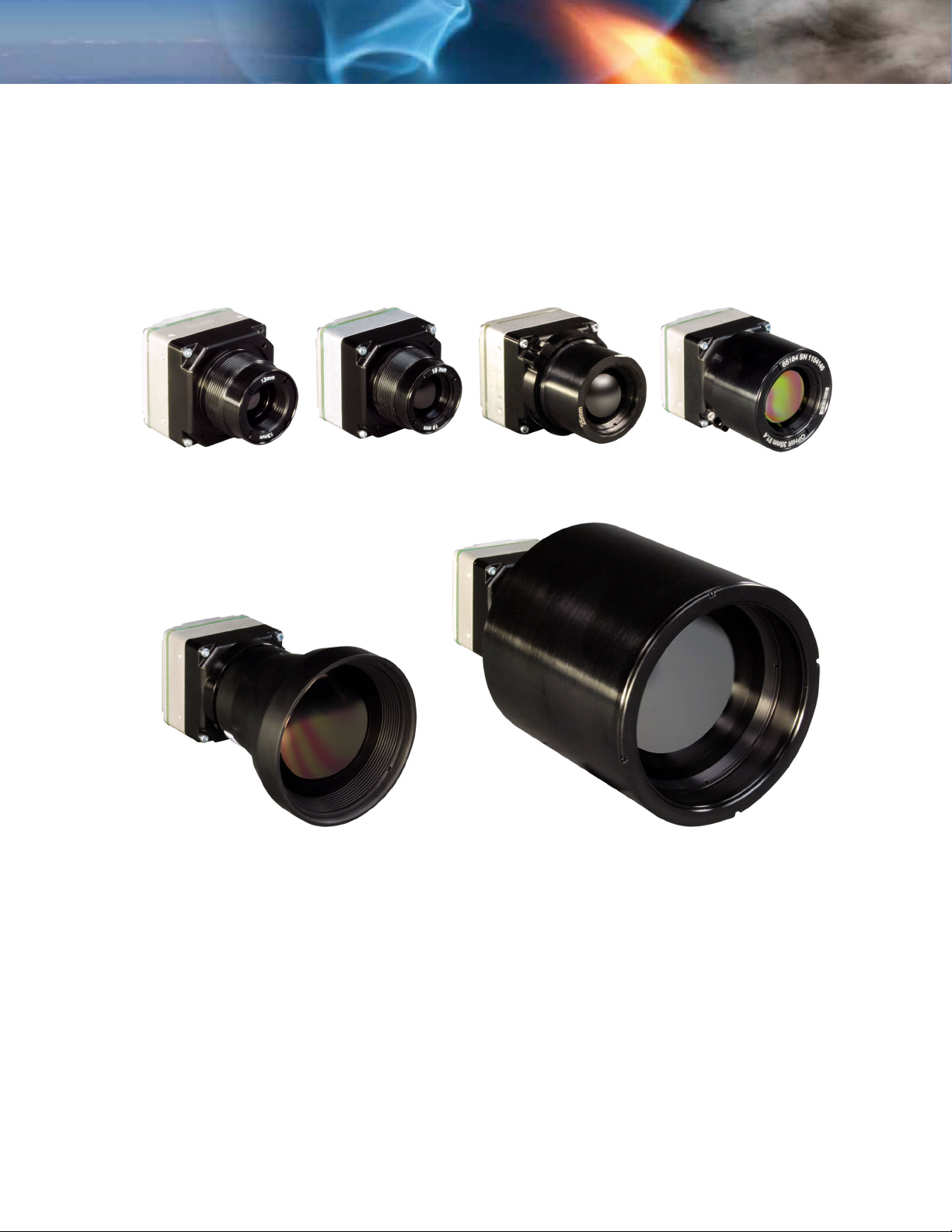
The Tau 640 camera is a long-wavelength (8 – 14 microns) uncooled microbolometer camera
designed for infrared imaging applications that demand absolute minimum size, weight, and
power consumption. It is available with multiple different lens focal length options, as well as
lens-less (not shown) and narrow-field-of-view (NFOV) options.
The Tau 640 Software Developer’s Kit (SDK) enables camera control using one of several
programming languages including VB6, VB.net, C#, and C++ (MFC). The FLIR Camera
Controller GUI is an example of an application created using the SDK—See “Software Accessory
SDK for Windows & Embedded” on page 2-4.
13 mm
(45° HFOV)
60 mm
(10.4° HFOV)
19 mm
(32° HFOV)
Figure 1-1: Tau 640 Cameras
25 mm
(25° HFOV)
35 mm
f/1.4
(18° HFOV)
100 mm
(6.2° HFOV)
The camera provides “power-in, video-out” capability, which means that one need only apply input
voltage to receive analog video. For those applications requiring serial control, the Tau 640
camera includes a serial interface (RS-232) for transmitting camera commands and receiving
status. The Tau 640 camera also provides 8-bit and 14-bit digital data options, including CMOS,
BT.656, and the Legacy Photon LVDS—See “Tau 640 Digital Data Channel” on page 4-1.
TAU-0640-00-10, version 110 June 2011 1-1

1—Introduction Tau 640 User’s Manual
1.1 Available Tau 640 Configurations
The Tau 640 camera is available with different lenses providing different fields of view. An
export license is required in order for international customers to purchase faster frame rate
versions of the Tau 640 camera. US customers can specify the 30 Hz (25 Hz) versions of the
Tau 640 camera.
Weight with
lens
13 mm
19 mm
25 mm
35 mm
60 mm
100 mm
Resolution f/# FOV (H × V)
640 × 480 (NTSC)
640 × 512 (PAL)
640 × 480 (NTSC)
640 × 512 (PAL)
640 × 480 (NTSC)
640 × 512 (PAL)
640 × 480 (NTSC)
640 × 512 (PAL)
640 × 480 (NTSC)
640 × 512 (PAL)
640 × 480 (NTSC)
640 × 512 (PAL)
1.25 45° × 37° 80 g
1.25 32° × 26° 80 g
1.4 25° × 20° 106 g
1.4 18° × 14° 129 g
1.25 10.4° × 8.3° 150 g
1.6 6.2° × 5.0° 503 g
Note
The Tau 640 camera lenses are sealed to IP67 (1 meter). The camera itself is sealed only
forward of the WFOV o-ring seal or the lens barrel of the NFOV lenses.
Boresight features are available on Tau 640 WFOV cameras. See “Mechanical IDD
Reference” on page D-1.
Contact FLIR Commercial Systems Customer Support or your local FLIR sales representative
for information on available Tau 640 camera configurations, part numbers, and ordering
information.
All the above lenses are sealed to IP67 (1 meter). All lenses, except the 35 mm, are diamondlike coated for superior abrasion resistance. The 35 mm lens is High Durability coated.
1-2 June 2011 TAU-0640-00-10, version 110
Tau 640 User’s Manual 1—Introduction
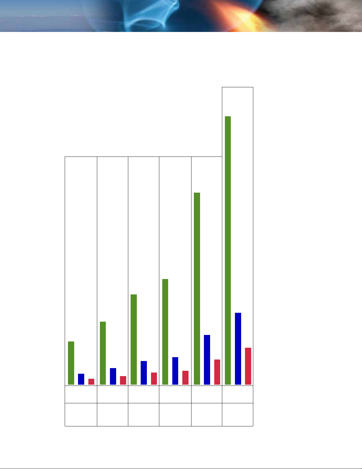
2450 meters—
Detection
390 meters—Detection
95 meters—Recognition
47 meters—Identification
570 meters—Detection
144 meters—Recognition
1750 meters—
Detection
960 meters—Detection
820 meters—Detection
650 meters—Recognition
450 meters—Recognition
330 meters—Identification
245 meters—Recognition
210 meters—Recognition
72 meters—Identification
104 meters—Identification
122 meters—Identification
225 meters—Identification
45°
HFOV
32°
HFOV
25°
HFOV
18°
HFOV
°
10.4
HFOV
6.2°
HFOV
Table 1-1: Tau 640 Camera Lens Range Performance (Standing Man—1.5m by 0.5m)
13mm
Lens
19mm
Lens
25mm
Lens
35mm
Lens
(f/1.4)
60mm
Lens
100mm
Lens
TAU-0640-00-10, version 110 June 2011 1-3

1—Introduction Tau 640 User’s Manual
1.2 Tau 640 Specifications
An export license is required in order for international customers to purchase faster frame rate
versions of the Tau 640 camera. US customers can specify the 30 Hz (25 Hz) versions of the
Tau 640 camera.
The latest information concerning specifications, accessories, camera configurations, and
other information can be found in the Tau 640 Thermal Imaging Camera Core Data Sheet at:
www.flir.com/cvs/cores/uncooled/products/tau/tau640/
• 640 (H) × 512 (V) uncooled microbolometer sensor array,
17 × 17 micron pixels
• Spectral band: 7.5 - 13.5μm
• NEdT Performance: < 50mK at f/1.0
• Input voltage range: 4.4 – 6.0 VDC
• Power Consumption: ~ 1.0 Watts (nominal at room temperature using 5V input)
• Time to image: ~ 3 seconds
• Operating Temperature Range: -40°C to +80°C
1
.
•Weight: < 55 grams (with shutter, no lens)
Note
The Tau 640 camera is an export controlled item. The ‘Slow Video’ version of the camera
is the baseline version. The frame rate is less than 9 Hz. This allows the Tau 640 camera
to be exported without US export license to most countries.
Additional information can be found under the
www.flir.com/cvs/cores/uncooled/products/tau/tau640
• Analog video output:
NTSC (640 × 480) 7.5Hz ‘Slow Video’ rate or 30Hz (US and Export License
customers only)
or
PAL (640 × 512) 8.3Hz ‘Slow Video’ rate or 25Hz (US and Export License
customers only)
Export tab at:
.
Note
The NTSC analog video format is default for cameras with analog video. The FLIR Camera
Controller GUI software (free download) allows you to select between NTSC or PAL video
output formats and save this configuration.
• Digital video output: 8- or 14-bit serial LVDS, CMOS, or BT.656
• Remote camera control RS-232 interface: FLIR Camera Controller GUI software
available for free download at www.flir.com/cvs/cores/resources/software/tau/
.
•2×, 4×, and 8× Digital Zoom with electronic pan/tilt (analog video)
• Dynamic Digital Detail Enhancement (DDE)
1. NEdT at the camera output measured with FLIR's proprietary noise reduction applied in the asshipped configuration. Typical performance is approximately 35mK with f/1.0 optics.
1-4 June 2011 TAU-0640-00-10, version 110

Tau 640 User’s Manual 1—Introduction
1.3 Unpacking Your Tau 640 Camera
The Tau 640 camera is typically delivered as a component part for incorporation into an original
equipment manufacturer’s (OEM) product; no documentation is included. Documentation and
utilities such as the latest version of this User’s Manual, the FLIR Camera Controller GUI, and
Mechanical Interface Description Documents are available for download from www.flir.com/
cvs/cores/uncooled/products/tau/tau640/.
When unpacking the camera, please heed customary electrostatic discharge (ESD) sensitive
device precautions including static safe work station and proper grounding. The Tau 640
camera is packaged in foam to prevent damage during shipping. It is also placed in a conductive
anti-static bag to protect from electrostatic discharge damage.
Caution!
Disassembling the camera can cause permanent damage and will void the warranty.
Operating the camera outside of the specified input voltage range or the specified operating
temperature range can cause permanent damage.
The camera back is not sealed. Avoid exposure to dust and moisture.
This camera contains electrostatic discharge sensitive electronics and should be handled
appropriately.
TAU-0640-00-10, version 110 June 2011 1-5

1—Introduction Tau 640 User’s Manual
1-6 June 2011 TAU-0640-00-10, version 110
2 Optional Tau 640 Camera Accessories
Accessories for your Tau 640 camera can be purchased from the online FLIR Camera
Accessory Store located at www.flirshop.com
.
2.1 Tau 640 VPC Module Accessory
The VPC (video, power, communications) module is an expansion board for the Tau 640 camera
that provides a convenient way for customers to power and communicate with the camera via
USB. The VPC module also incorporates an MCX connector that outputs analog video.
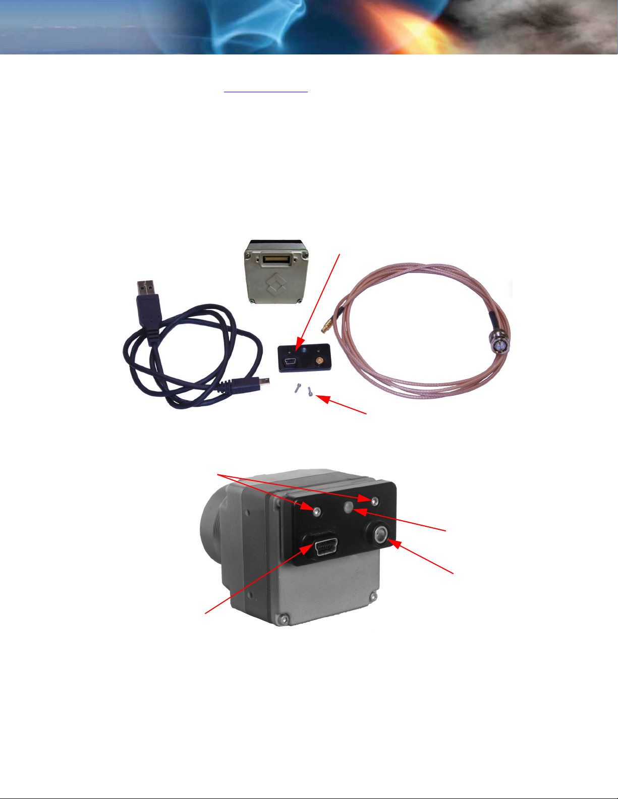
The VPC module accessory includes a USB-A to USB-mini B cable for power and
communications, an MCX-to-BNC cable for analog video, and mounting screws. For instructions
on installing the VPC Module refer to paragraph 3.1.1 “Installing the VPC Module” on page 3-1.
VPC Module
USB cable
Video cable
Socket head cap screws
(M1.6 × 0.35 × 6 mm)
Figure 2-1: Tau 640 Camera and VPC Module Accessory Kit
Mounting screws
M1.6 × 0.35 × 6 mm SHCS
Power status light
MCX coaxial
Mini USB
Figure 2-2: Tau 640 VPC Module Installed on a Tau 640 camera
The Tau 640 camera with the VPC module is powered with a nominal draw of 212 mA at 5VDC
and a peak startup draw of 550 mA. The camera uses serial communication at either 57600
or 921600 Baud by creating a virtual COM Port on your computer for USB communications.
The Baud Rate is selected using auto-Baud and the camera will communicate at the first Baud
Rate in which it receives a valid command until it is powered off.
TAU-0640-00-10, version 110 June 2011 2-1

2—Optional Tau 640 Camera Accessories Tau 640 User’s Manual
2.2 Tau 640 Camera Link Module Accessory
The Camera Link module is an expansion board for the Tau 640 camera that provides a
convenient way for customers to power and communicate with the camera via USB and access
LVDS digital video with a high-speed Camera Link channel. The Camera Link module also
incorporates an MCX connector that outputs analog video.
The Camera Link module takes CMOS-type digital data from the Tau 640 camera and converts
it to Camera Link. In order to use a Camera Link module for acquisition of data, you will need to
first enable the CMOS XP Bus Output using the FLIR Camera Controller GUI. See “Digital Video
Tab” on page 3-19. On this same page, you can select either 8-bit or 14-bit digital output. Once
you make these changes, it is a good idea to save settings to make them power cycle
consistent. See “Save Settings” on page 3-13.
The Camera Link module accessory comes with the spacers and mounting screws shown in
Figure 2-3. Note that Camera Link cable, frame grabber, or capture software are not included.
For instructions on installing the Camera Link module, refer to paragraph 3.1.2 “Installing the
Camera Link Module” on page 3-2.
Mounting screws
M1.6 × 0.35 × 8 mm SHCS
MCX coaxial
(analog video)
Mini Camera Link
(digital video)
Spacer
Ø3 mm × 3.1 mm
M1.6 × 0.35 × 16 mm SHCS
Figure 2-3: Tau 640 Camera Link Module Installed on a Tau 640 camera
Power status light
Mini USB
Mounting screws
The Tau 640 camera with the Camera Link module is powered with a nominal draw of 270 mA
at 5VDC and a peak startup draw of 550 mA. The camera uses serial communication at either
57600 or 921600 Baud by creating a virtual COM Port on your computer for USB
communications. The Baud Rate is selected using auto-Baud and the camera will communicate
at the first Baud Rate in which it receives a valid command until it is powered off.
The digital data complies with Base Camera Link standards and should be compatible with any
brand Camera Link Frame Grabber and software. The FLIR Camera Controller allows for control
of the Tau 640 camera, but does not support Camera Link frame capture and third-party
software must be used.
External sync is not possible with the Camera Link module.
2-2 June 2011 TAU-0640-00-10, version 110

Tau 640 User’s Manual 2—Optional Tau 640 Camera Accessories
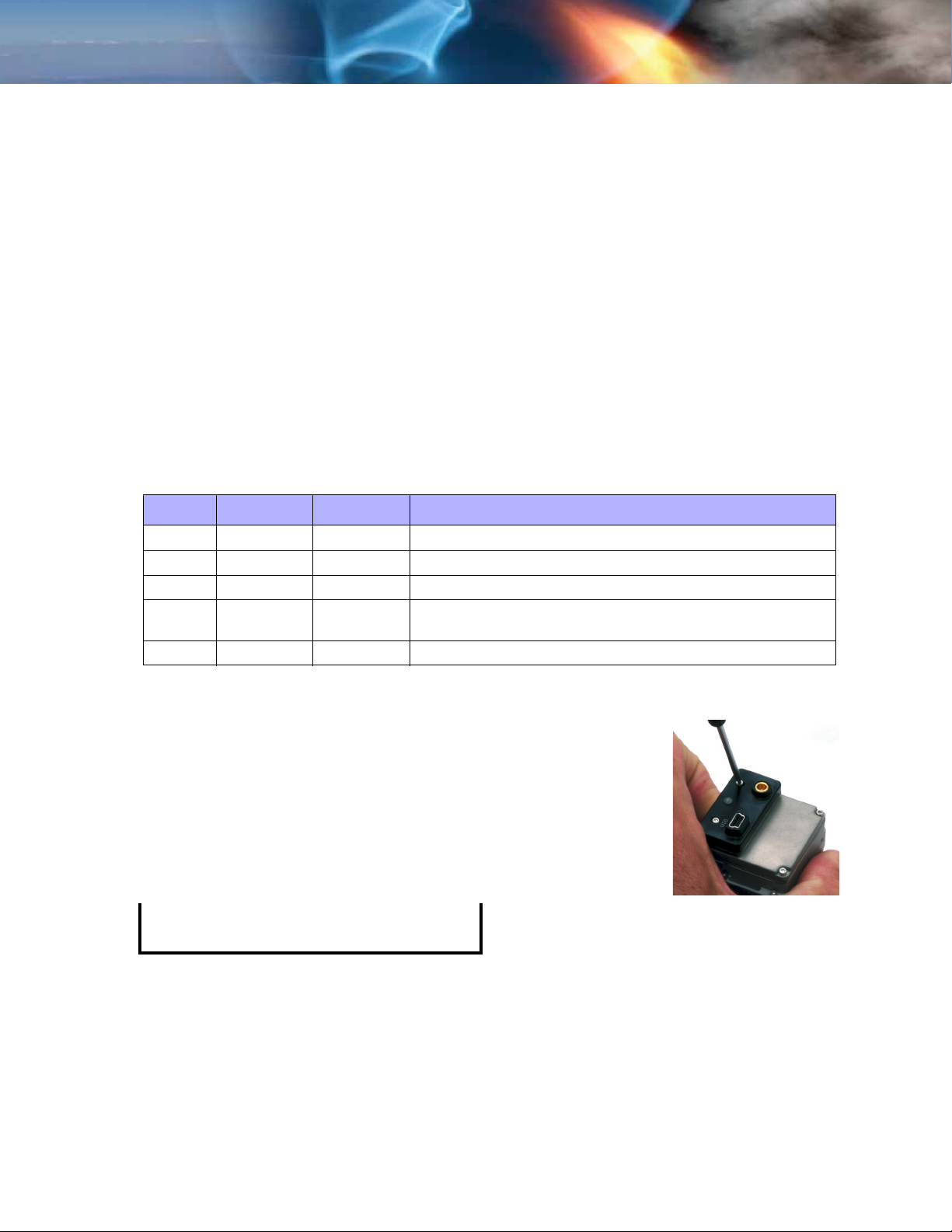
2.3 Tau 640 WFOV Locking Ring and Tool
Tau 640 Locking Ring Accessory,
421-0041-00
Lock Nut Tool,
421-0042-00
Type 2 - 025 O-ring
(not included)
The locking ring is designed to mount a Tau 640 WFOV
camera into a bulkhead. The M29 x 1.0 thread on the
outside of the lens mount flange is placed through the
clearance hole in the bulkhead and the o-ring seals the
camera to the face.
The Type 2-025 O-ring is not for sale through FLIR. This is
a standard o-ring available from many suppliers.
The locking ring accessory is made of Delrin so as not to
scratch the Tau 640 camera lens flange. Scratching the
external plating can compromise the coating and make
the Tau 640 camera more susceptible to corrosion. The
lock nut tool will attach to a torque wrench for proper
tightening. Torque the locking ring to 4.0 in-lbs.
2.4 Tripod Mount for Tau 640 Camera
Tripod mount,
261-2071-00
This accessory adapts two of the mounting points on the
Tau 640 camera to a standard 1/4
mounting plate. The tripod adapter mounts to the
bottom of Tau 640 camera using two furnished socket
head screws.
” x 20 tripod
2.5 Photon Replicator Board
Photon Replicator Board,
421-0040-00
This expansion board adapts the Tau 640 camera's
native 50-pin Hirose connector to the 30-pin SAMTEC
connector used on FLIR's Photon cameras. The
replicator board makes the Tau 640 camera
electrically pin-compatible to a Photon camera,
including the provision for operating the Tau 640
camera over a similar input voltage range as the
Photon camera: 6.5-27 VDC.
A cast magnesium spacer and 4 socket-head machine screws are included.
TAU-0640-00-10, version 110 June 2011 2-3

2—Optional Tau 640 Camera Accessories Tau 640 User’s Manual
2.6 Software Accessory Alternate Lens Calibration Software
110-0133-72
For customers that furnish their own optics for use with Tau 640 cores, FLIR sells a Windows
application program called Alt Lens Cal. This software enables users to perform a
supplementary calibration of the camera with a lens. This field-calibration process requires the
use of at least one blackbody source (a uniform, controllable temperature reference) that has
an area greater than the diameter of the front of the lens.
The Alt Lens Cal software also requires a customer-furnished PC, which should be dedicated to
this task. The calibration routine calculates gain terms on a per-pixel basis with the customersupplied lens attached to the Tau 640 core, and stores the customer-performed calibration in
non-volatile camera memory. The original factory calibration coefficients are first uploaded from
the camera and stored into a file on the PC, then the new calibration data is downloaded and
stored directly into the camera. Multiple calibration files can be stored on the host computer.
The original factory calibration file can be restored if necessary, and the customer can actually
build a library of lens calibration files for a Tau 640 camera. All OEM customers who add their
own lenses to Tau 640 should use this program for optimal image performance.
Alternately, customers can contact FLIR to purchase a Lens Calibration feature that works with
the FLIR Camera Controller GUI software. Specifically, a DLL can be added to the FLIR Camera
Controller GUI software that provides all the features of the stand-alone Alt Lens Cal software.
2.7 Software Accessory SDK for Windows & Embedded
110-0133-16
The Tau 640 Software Developer’s Kit enables camera control using one of several
programming languages including VB6, VB.net, C#, and C++ (MFC). Code examples are
included to help illustrate how some of the camera control functions can be used. The FLIR
Camera Controller GUI is an example of an application created using the Tau 640 SDK.
Refer to www.flir.com/cvs/cores/resources/software/tau/
.
2-4 June 2011 TAU-0640-00-10, version 110
3 Basic Operation of the Tau 640 and GUI
3.1 Operation of the Tau 640 Camera using the USB Interface
The Tau 640 VPC Module and Camera Link Module are USB interfaces for the camera to
provide power and serial communication for more advanced camera command and control via
the free downloadable FLIR Camera Controller GUI. Both modules provide an analog video
output, while the Camera Link Module also provides a digital video output in the Camera Link
format. Camera Link command and control functions are not supported, only the camera link
digital video output is provided.
Connector Type: USB mini 5-pin
Power over USB VPC: nominal draw 212 mA at 5 V
(peak load at startup 550 mA at 5V)
Power over USB Camera Link: nominal draw 270 mA at 5 V
(peak load at startup 550 mA at 5V)
Serial communications baud rate: 57600 Baud or 921600 Baud
Hot swap protected
Windows Service for automatic detection supported through SDK
Table 3-1: Miniplug / Microplug
Pin Name Color Description
1VCC Red+5 V
2 D- White Data -
3D+GreenData +
4
5 GND Black Signal Ground
1. Pin 4 of mini-USB connector may be not connected, connected to GND, or used as attachment identification
at some portable devices.
1
ID
none
permits distinction of Micro-A- and Micro-B-Plug
Type A: connected to Ground, Type B: not connected
3.1.1 Installing the VPC Module
Step 1 Plug the VPC Module into the mating 50-pin
Hirose Connector on the back of the Tau 640
camera.
Step 2 Using a 1.5 mm socket driver, install the two
socket head cap screws to secure the VPC
Module.
Note
Use only M1.6 × 0.35 × 6 mm screws.
Longer screws will damage the camera.
TAU-0640-00-10, version 110 June 2011 3-1
3—Basic Operation of the Tau 640 and GUI Tau 640 User’s Manual
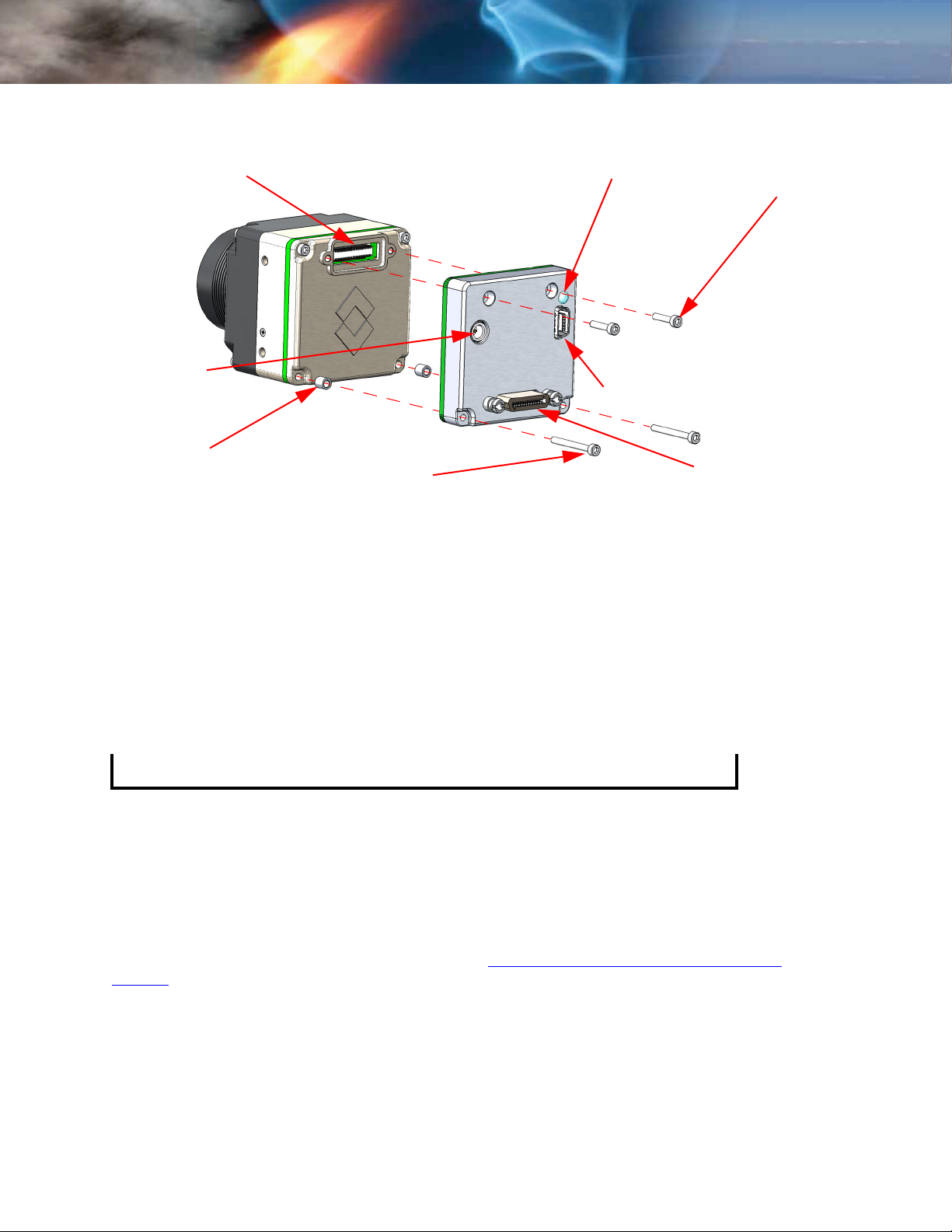
3.1.2 Installing the Camera Link Module
Hirose Connector
MCX coaxial
(analog video)
Spacer (2)
Ø3 mm × 3.1 mm
Power status light
Mini USB
Mounting screw (2)
M1.6 × 0.35 × 16 mm SHCS
Mounting screw (2)
M1.6 × 0.35 × 8 mm SHCS
Mini Camera Link
(digital video)
Step 1 Using a 1.5 mm socket driver, remove the two case screws at the bottom of the
camera (opposite connector).
Step 2 Insert the two M1.6 × 0.35 × 16 mm socket head cap screws through the corner
holes of the Camera Link module, install the spacers on the screws, and thread the
screws into the camera to replace the case screws removed earlier.
Step 3 Plug the module connector into the mating 50-pin Hirose Connector on the back of
the Tau 640 camera.
Step 4 Install the two M1.6 × 0.35 × 8 mm socket head cap screws to secure the module at
the connector.
Note
Use only M1.6 × 0.35 × 8 mm screws. Longer screws will damage the camera.
Step 5 Finish tightening the two M1.6 × 0.35 × 16 mm socket head cap screws at the
corners of the case.
The digital data complies with the Base Camera Link standard and should be compatible with
any brand Camera Link Frame Grabber and software.
The FLIR Camera Controller allows you to control the Tau Camera, but does not support
Camera Link frame capture so that a third-party software must be used. FLIR has tested the
ImperX FrameLink Express frame grabber (http://imperx.com/frame-grabbers/framelink-
express).The ImperX frame grabber comes with FrameLink Express software that allows for
recording single or multiple images (BMP, JPG, TIF, and RAW) as well as standard AVI clips.
Configuration requires selecting 1 TAP, L->R for the tap reconstruction, selecting the
appropriate bit depth that you chose in the FLIR Camera Controller, and clicking “Learn” to
discover the number of digital pixels available.
3-2 June 2011 TAU-0640-00-10, version 110
Tau 640 User’s Manual 3—Basic Operation of the Tau 640 and GUI
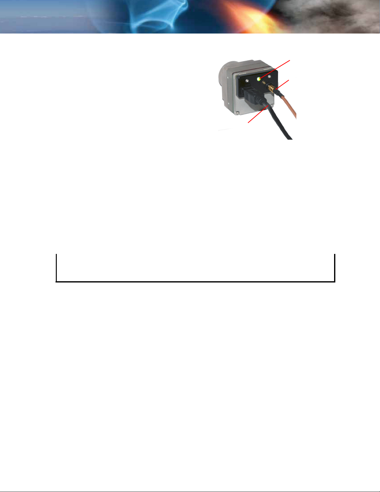
3.1.3 Connecting the Tau 640 Camera for Analog Video
Plug the Video cable into the mating connector on the
back of the camera. Attach the other end to a
compatible video monitor’s composite video input. If
your monitor has an RCA input connector, a BNC to
RCA adapter can be used.
Plug the mini USB plug into the mating connector on
the back of the camera. Connect the other end of the
cable to a USB port on the computer. At this point,
you are only using the power from the USB port.
USB cable
to computer
Power light
Analog video out
3.2 Remote control of the Tau 640 Camera
The Tau 640 camera with a Universal Serial Bus (USB) interface accommodates advanced
camera control through the FLIR Camera Controller GUI. A user also can control the camera
through this interface using their own software and hardware by following the Serial
Communication Protocol and command structure defined in Appendix B. This requires
programming skills and a strong technical background. The FLIR Camera Controller GUI is
offered as a free download from FLIR using a Windows based PC with a standard USB port.
This software provides remote control of various camera features and modes.
The FLIR Camera Controller GUI software is compatible with Windows XP with .Net Framework
version 2.0 or later. The GUI will prompt the user to update to the latest .Net Framework.
Note
We recommend that Windows Update is turned on, keeping the operating system current;
and that you use the latest version of the FLIR Camera Controller GUI
(available on our website).
If your embedded or specialty applications require custom control software, a Software
Developer’s Kit (SDK) is available. Those intending to generate their own custom software are
encouraged to read the remainder of this section regarding the FLIR Camera Controller GUI to
better understand the camera modes and parameters.
TAU-0640-00-10, version 110 June 2011 3-3
3—Basic Operation of the Tau 640 and GUI Tau 640 User’s Manual
3.3 Installing the FLIR Camera Controller GUI
Step 1 If you have another version of the FLIR Camera Controller GUI loaded on your PC, you
should uninstall it using the Windows Uninstall utility via the Windows Control Panel
before proceeding with this installation. This is an important step as camera
malfunction is possible if you do not remove any older versions of Tau 640 (or
Omega/Micron/A10) software.
Step 2 Using your favorite WWW browser, navigate to the following URL:
www.flir.com/cvs/cores/resources/software/tau/
Step 3 Click the Tau GUI link.
Step 4 When the File Download prompt appears, choose Save. It is recommended that you
create a new empty directory such as “FLIR Camera Controller GUI Installable Files”
on your desktop, for download.
Step 5 Extract the Installable files using WinZip or other available software.
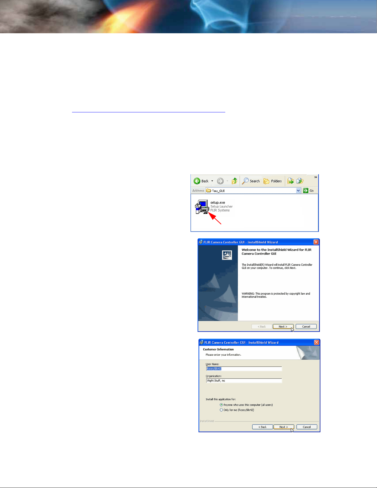
Step 6 Open the directory where you saved
the Installable files. Double-click the
setup.exe file to begin installation.
.
Step 7 Click Next> at the Setup Welcome
screen.
When the installer finishes loading. Follow
the prompts.
Step 8 Enter your User Name, Organization, and
select your access security.
Click Next>
Camera Controller GUI
3-4 June 2011 TAU-0640-00-10, version 110
Tau 640 User’s Manual 3—Basic Operation of the Tau 640 and GUI
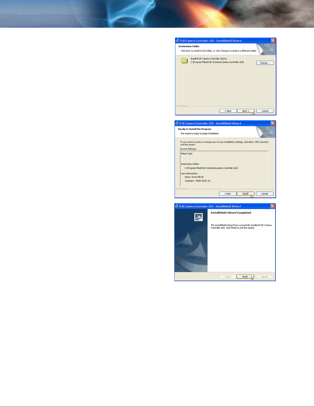
Step 9 Select a Destination Folder if different
than the default.
Then, click Next>>.
Step 10 Review the settings you have entered for
this installation.
Then, click Install
Step 11 Once installation is complete, click Finish.
TAU-0640-00-10, version 110 June 2011 3-5
3—Basic Operation of the Tau 640 and GUI Tau 640 User’s Manual
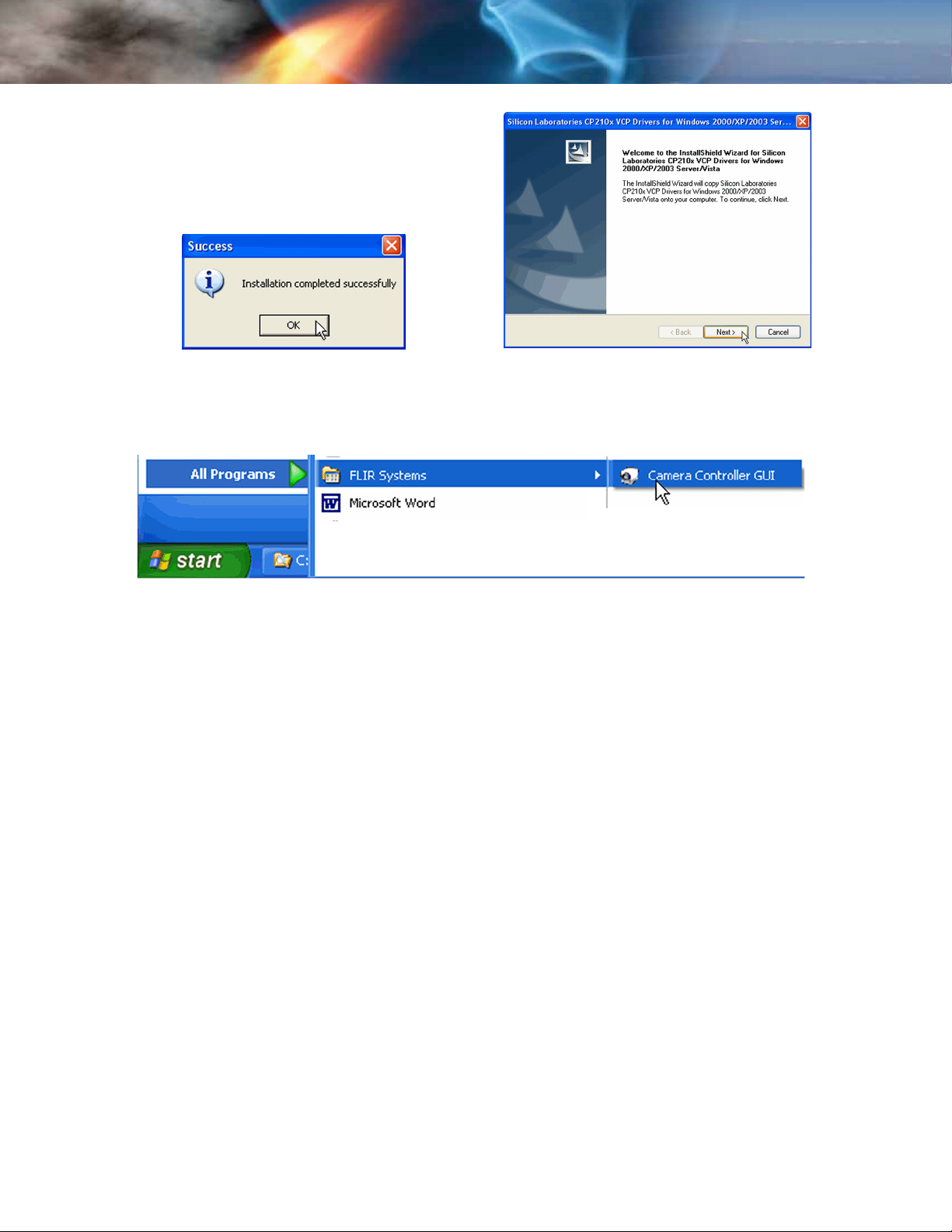
Step 12 The CP210x_VCP...setup.exe USB driver
installer will start at this point.
Click Next> at the Setup Welcome
screen.
When the installer finishes loading. Follow
the prompts to finish the installation.
Step 13 Installation is complete. You can start the application or create a shortcut to the
application via the
Start→ All Programs→ FLIR Systems→ Camera Controller GUI path.
3-6 June 2011 TAU-0640-00-10, version 110
Tau 640 User’s Manual 3—Basic Operation of the Tau 640 and GUI
3.4 Connecting the Tau 640 to a PC via USB
The following steps assume that you have installed the FLIR Camera Controller GUI software
and the USB driver on your PC as described in the proceeding paragraphs 3.3.
Step 1 Follow the steps in paragraph 3.1.3 “Connecting the Tau 640 Camera for Analog
Video” on page 3-3.
About two seconds after the USB cable from the camera is connected to your PC, you
should see video on your monitor. Verify that the camera is producing an image.
Step 2 Launch the FLIR Camera Controller GUI software by selecting Start→ Programs→ FLIR
Systems→ Camera Controller GUI.
Note
The FLIR Camera Controller GUI remembers the last COM port that successfully
communicated with a Tau 640 camera and will use that port as the default when the
application starts. If the connected camera is no longer on that port, the port setting pop-up
window will appear asking for you to select the proper port setting.
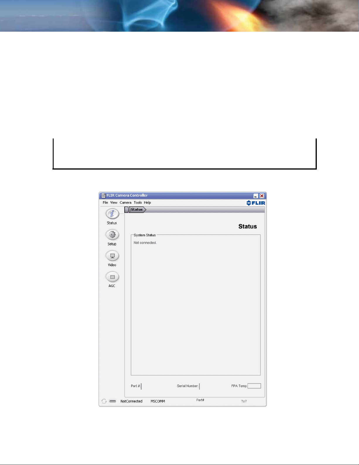
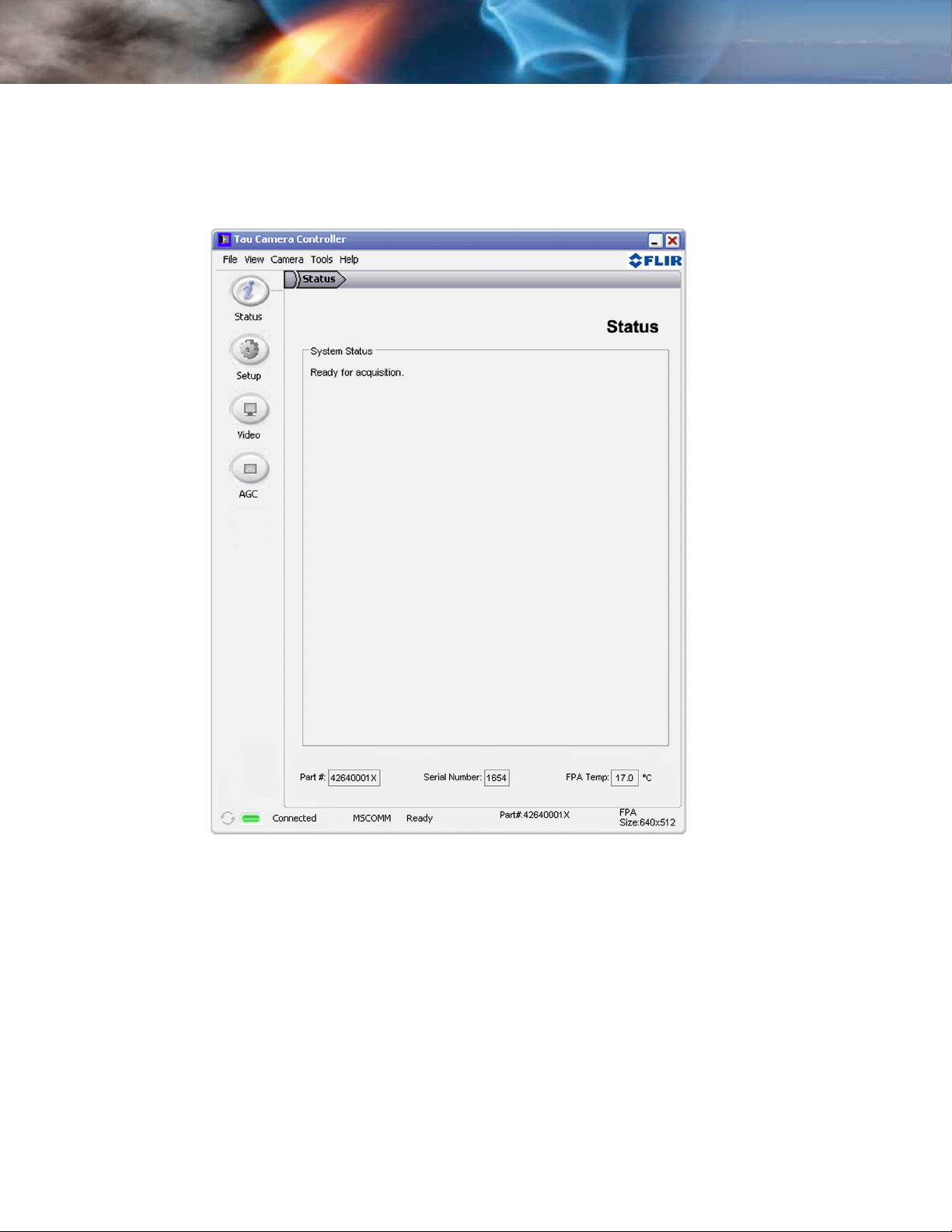
When the FLIR Camera Controller GUI is started, the Status tab of the utility should
return data similar to the following.
Figure 3-1: FLIR Camera Controller GUI Status Tab
TAU-0640-00-10, version 110 June 2011 3-7
3—Basic Operation of the Tau 640 and GUI Tau 640 User’s Manual
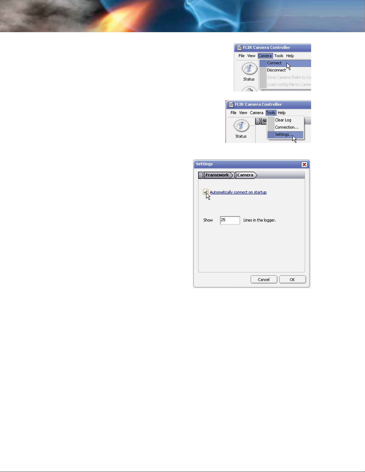
Step 3 Connect to your camera by selecting Connect from the
Camera menu.
Step 4 If you want the FLIR Camera Controller GUI
to automatically connect when it is started,
select Settings from the Tools menu, then
check the Automatically connect on
startup box in the Settings Framework tab.
Additional settings include camera
connection polling, status logging,
and FLIR Veneer style.
3-8 June 2011 TAU-0640-00-10, version 110
Tau 640 User’s Manual 3—Basic Operation of the Tau 640 and GUI
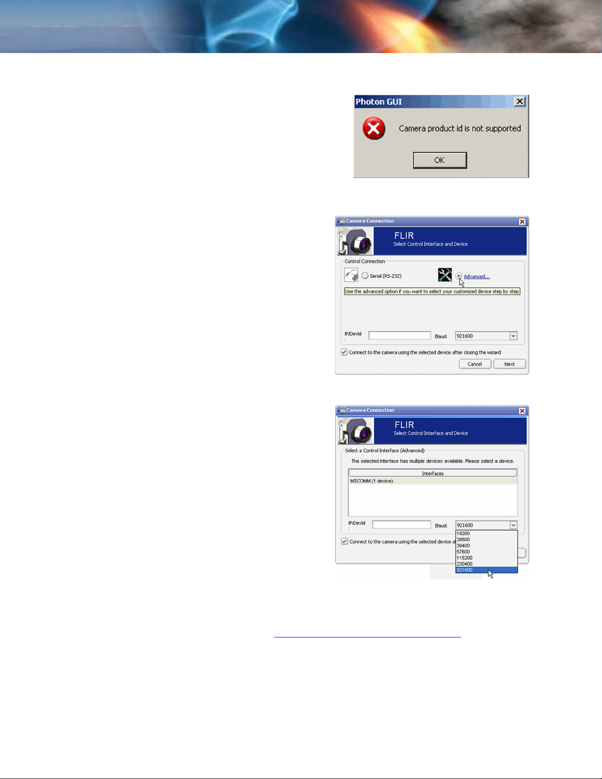
3.5 Troubleshooting the FLIR Camera Controller GUI
If the FLIR Camera Controller GUI does not link
with the camera, you may see the popup shown at
the right which indicates that the GUI has not
been able to communicate with the Tau 640
camera.
Verify the items in the following checklist:
Is the camera properly cabled to the
host PC?:
Verify that you selected the proper port if it was
not detected automatically. Select Advanced, then
Next> in the Tools→ Connection... dialog box. Also,
try disconnecting and then re-connecting the cable
to the PC. If the GUI was launched before the
cable was connected, close the GUI, connect the
cable, then re-launch the GUI.
Is the Baud rate set correctly? Baud
rate must be set in the Tools→ Connection...
dialog box. The Tau 640 camera supports Baud
rates of 57600 and 921600.
Is the port already in use by another
application?:
Shut down any other applications that may be
using the port. Also, multiple instances of the FLIR
Camera Controller GUI Program can be
instantiated using different ports so be sure the
camera you are interested in controlling is actually
connected to the physical port.
Is the Tau 640 camera power on?
Verify that the camera is producing an image on a
separate monitor. On cameras with a shutter
installed, at camera power up, you can hear two
sets of a click-click sound, separated by about 5
seconds, as the shutter performs its on-power-up calibration.
If you cannot initiate serial communication with the camera after verifying these items, refer to
the frequently asked questions (FAQ) at www.flir.com/cvs/cores/faqs/tau/all/
or contact FLIR Customer Support at (805) 964-9797.
TAU-0640-00-10, version 110 June 2011 3-9
3—Basic Operation of the Tau 640 and GUI Tau 640 User’s Manual
3.6 Operation of the FLIR Camera Controller GUI
When the FLIR Camera Controller GUI successfully links to the camera, you will see the window
shown below. At the bottom of the application window, you should see Camera and FPA status.
The GUI provides five tabs allowing for camera control as described below.
Figure 3-2: FLIR Camera Controller GUI Status Tab
Camera Part #: indicates the specific camera configuration connected.
Camera Serial #: This is the serial number of the camera currently connected to the FLIR
Camera Controller GUI.
FPA Temperature: The camera’s Focal Plane Array (FPA) temperature.
The connection status, Camera status, Camera Part #, FPA Temp, and FPA Size are displayed
at the bottom of all tabs.
3-10 June 2011 TAU-0640-00-10, version 110
Tau 640 User’s Manual 3—Basic Operation of the Tau 640 and GUI
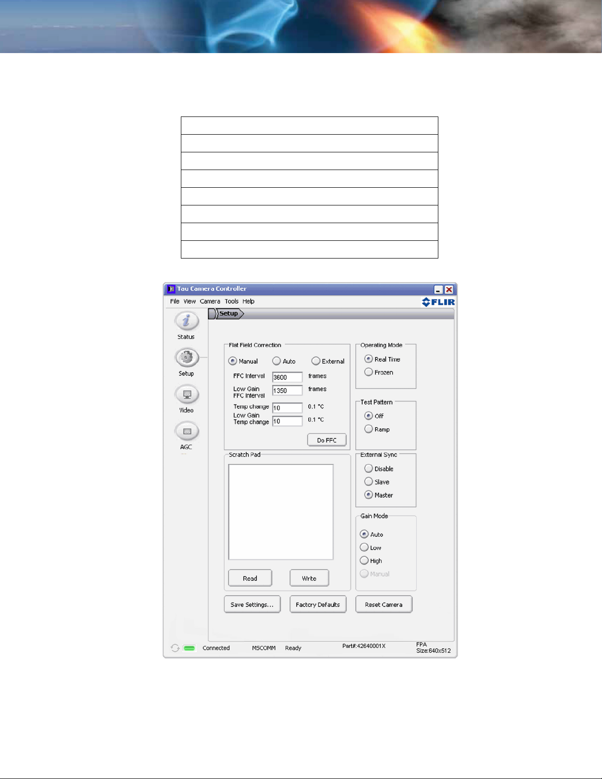
3.7 Setup Tab
The Setup tab, shown below, provides the ability to do the following:
Modify the Flat Field Correction (FFC)
Set the External Sync mode
Freeze the video via the Operating Mode section
Populate the Scratch Pad with text
Set the camera to generate a Test Pattern
Save the settings to the camera’s non volatile memory
Restore the Factory Defaults
Reset the Camera
Figure 3-3: FLIR Camera Controller GUI Setup Tab
TAU-0640-00-10, version 110 June 2011 3-11
 Loading...