

Page 1
User’s manual
FLIR T6xx series
Page 2

Page 3

User’s manual
FLIR T6xx series
#T559598; r. AB/ 9443/9443; en-US
iii
Page 4

Page 5

Table of contents
1 Legal disclaimer ............................................... ....... ....... ................... 1
1.1 Legal disclaimer .......................................................................1
1.2 Usage statistics ........................................................................ 1
1.3 Changes to registry ................................................................... 1
1.4 U.S. Government Regulations......................................................1
1.5 Copyright ................................................................................1
1.6 Quality assurance .....................................................................1
1.7 Patents...................................................................................1
1.8 EULA Terms ............................................................................1
2 WARNING, CAUTION................................. ........................................ .2
3 Notice to user .... ................... ....... ....... ....... ................................. ......5
3.1 User-to-user forums .................................................................. 5
3.2 Calibration...............................................................................5
3.3 Accuracy ................................................................................ 5
3.4 Disposal of electronic waste ........................................................5
3.5 Training ..................................................................................5
3.6 Documentation updates ............................................................. 5
3.7 Important note about this manual..................................................5
4 Customer help ....... ....... ................... ....... ....... ....... ............................6
4.1 General ..................................................................................6
4.2 Submitting a question ................................................................ 6
4.3 Downloads ..............................................................................6
5 Parts lists ............................................. ....... ................................. ....7
5.1 Scope of delivery ......................................................................7
5.2 List of accessories and services................................................... 7
6 Quick Start Guide ........................... ....... ....... .......................... ....... .. 10
6.1 Procedure ............................................................................. 10
7 A note about ergonomics .... ............................................................. 11
7.1 General ................................................................................ 11
7.2 Figure .................................................................................. 11
8 Camera parts .................................................................................. 12
8.1 View from the right .................................................................. 12
8.1.1 Figure........................................................................ 12
8.1.2 Explanation................................................................. 12
8.2 View from the left .................................................................... 13
8.2.1 Figure........................................................................ 13
8.2.2 Explanation................................................................. 13
8.3 View from the rear................................................................... 14
8.3.1 Figure........................................................................ 14
8.3.2 Explanation................................................................. 14
8.4 View from the bottom............................................................... 15
8.4.1 Figure........................................................................ 15
8.4.2 Explanation................................................................. 15
8.5 Battery condition LED indicator .................................................. 16
8.5.1 Figure........................................................................ 16
8.5.2 Explanation................................................................. 16
8.6 Power LED indicator ................................................................ 16
8.6.1 Figure........................................................................ 16
8.6.2 Explanation................................................................. 16
8.7 Laser pointer ......................................................................... 17
8.7.1 Figure........................................................................ 17
8.7.2 Laser warning label....................................................... 17
8.7.3 Laser rules and regulations ............................................ 17
#T559598; r. AB/ 9443/9443; en-US
v
Page 6

Table of contents
9 Screen elements ..... ........................................................................ 18
9.1 Main screen area.................................................................... 18
9.1.1 Figure........................................................................ 18
9.1.2 Explanation................................................................. 18
9.2 Status icons and indicators ....................................................... 18
10 Navigating the menu system.... ........................................ ....... .......... 20
10.1 Figure .................................................................................. 20
10.2 Explanation ........................................................................... 20
11 Connecting external devices and storage media .............. ....... ....... ..... 21
11.1 Figure .................................................................................. 21
11.2 Explanation ........................................................................... 21
12 Pairing Bluetooth devices................................................................. 22
12.1 General ................................................................................ 22
12.2 Procedure ............................................................................. 22
13 Configuring Wi-Fi ....... ....... ....... .......................... ....... ....... ............... 23
13.1 General ................................................................................ 23
13.2 Setting up a peer-to-peer connection (most common use) ............... 23
13.3 Connecting the camera to a wireless local area network (less
common use) .........................................................................23
14 Handling the camera.................. ....... ....... ........................................ 24
14.1 Charging the battery................................................................ 24
14.1.1 Using the power supply to charge the battery ..................... 24
14.1.2 Using the stand-alone battery charger to charge the
battery........................................................................24
14.2 Turning on the camera ............................................................. 24
14.2.1 Procedure .................................................................. 24
14.3 Turning off the camera ............................................................. 24
14.3.1 Procedure .................................................................. 24
14.4 Adjusting the viewfinder’s dioptric correction ................................. 25
14.4.1 Figure........................................................................ 25
14.4.2 Procedure .................................................................. 25
14.5 Adjusting the angle of the lens ................................................... 26
14.5.1 Figure........................................................................ 26
14.6 Adjusting the infrared camera focus manually ............................... 26
14.6.1 Figure........................................................................ 26
14.6.2 Procedure .................................................................. 26
14.7 Autofocusing the infrared camera ............................................... 27
14.7.1 Figure........................................................................ 27
14.7.2 Procedure .................................................................. 27
14.8 Continuous autofocus .............................................................. 27
14.8.1 General...................................................................... 27
14.8.2 Procedure .................................................................. 27
14.9 Operating the laser pointer........................................................ 28
14.9.1 Figure........................................................................ 28
14.9.2 Procedure .................................................................. 28
14.10 Using the digital zoom function .................................................. 29
14.10.1 Figure........................................................................ 29
14.10.2 Procedure .................................................................. 29
14.11 Changing lenses..................................................................... 29
14.12 Calibrating the compass........................................................... 32
14.12.1 Figure........................................................................ 32
14.12.2 Procedure .................................................................. 32
14.13 Calibrating the touchscreen LCD................................................ 32
14.13.1 Figure........................................................................ 32
14.13.2 Procedure .................................................................. 32
#T559598; r. AB/ 9443/9443; en-US
vi
Page 7

Table of contents
14.14 Changing the viewfinder’s eyecap............................................... 33
15 Working with images... ....... ....... .......................... ....... ....... ............... 35
15.1 Saving an image ..................................................................... 35
15.1.1 General...................................................................... 35
15.1.2 Image capacity ............................................................ 35
15.1.3 Naming convention....................................................... 35
15.1.4 Procedure .................................................................. 35
15.2 Previewing an image ............................................................... 35
15.2.1 General...................................................................... 35
15.2.2 Procedure .................................................................. 35
15.3 Opening an image................................................................... 36
15.3.1 General...................................................................... 36
15.3.2 Procedure .................................................................. 36
15.4 Adjusting an infrared image....................................................... 36
15.4.1 General...................................................................... 36
15.4.2 Example 1 .................................................................. 36
15.4.3 Example 2 .................................................................. 37
15.4.4 Changing the temperature scale level ............................... 37
15.4.5 Changing the temperature scale span............................... 37
15.5 Hiding overlay graphics (programmable button)............................. 37
15.5.1 General...................................................................... 37
15.5.2 Procedure .................................................................. 37
15.6 Changing the palette ............................................................... 38
15.6.1 General...................................................................... 38
15.6.2 Procedure .................................................................. 38
15.7 Deleting an image................................................................... 38
15.7.1 General...................................................................... 38
15.7.2 Procedure .................................................................. 38
15.8 Deleting all images.................................................................. 38
15.8.1 General...................................................................... 38
15.8.2 Procedure .................................................................. 39
15.9 Creating a PDF report in the camera ........................................... 39
15.9.1 General...................................................................... 39
15.9.2 Procedure .................................................................. 39
16 Working with image modes ...................................... ......................... 40
16.1 What is picture-in-picture? ........................................................ 40
16.2 What is thermal fusion? ............................................................ 40
16.3 Types ................................................................................... 40
16.4 Image examples ..................................................................... 40
16.5 Setting up Thermal fusion ......................................................... 41
16.6 Setting up picture-in-picture ...................................................... 42
16.7 Setting up MSX ...................................................................... 42
17 Working with measurement tools .......... ....... ....... ....... ................... .... 43
17.1 Laying out measurement tools: spots, areas, etc. ........................... 43
17.1.1 General...................................................................... 43
17.1.2 Procedure .................................................................. 43
17.2 Laying out measurement tool: isotherms ...................................... 43
17.2.1 General...................................................................... 43
17.2.2 Procedure .................................................................. 43
17.3 Working with presets ............................................................... 44
17.3.1 General...................................................................... 44
17.3.2 Procedure .................................................................. 44
17.4 Moving or resizing a measurement tool........................................ 44
17.4.1 General...................................................................... 44
17.4.2 Procedure .................................................................. 44
#T559598; r. AB/ 9443/9443; en-US
vii
Page 8

Table of contents
17.5 Creating and setting up a difference calculation ............................. 45
17.5.1 General...................................................................... 45
17.5.2 Procedure .................................................................. 45
17.6 Changing object parameters ..................................................... 46
17.6.1 General...................................................................... 46
17.6.2 Types of parameters ..................................................... 46
17.6.3 Recommended values................................................... 46
17.6.4 Procedure .................................................................. 46
17.6.5 Related topics ............................................................. 47
18 Fetching data from external Extech meters ... ....... ................... ....... ..... 48
18.1 General ................................................................................ 48
18.2 Figure .................................................................................. 48
18.3 Supported Extech meters ......................................................... 48
18.4 Technical support for Extech meters............................................ 48
18.5 Procedure ............................................................................. 48
18.6 Typical moisture measurement and documentation
procedure..............................................................................49
18.6.1 General...................................................................... 49
18.6.2 Procedure .................................................................. 49
19 Working with alarms and isotherms ...................... ....... ....... ............... 50
19.1 Measurement alarms ............................................................... 50
19.1.1 General...................................................................... 50
19.1.2 Types of alarm ............................................................. 50
19.1.3 Alarm signals .............................................................. 50
19.1.4 Procedure .................................................................. 50
19.2 Building isotherms .................................................................. 50
19.2.1 General...................................................................... 50
19.2.2 About the Humidity isotherm ........................................... 50
19.2.3 About the Insulation isotherm.......................................... 51
19.2.4 Setting up a Humidity alarm ............................................ 51
19.2.5 Setting up an Insulation alarm ......................................... 51
20 Annotating images ..... ....... ....... .......................... ....... ....... ............... 53
20.1 General ................................................................................ 53
20.2 Taking a digital photo ............................................................... 53
20.2.1 General...................................................................... 53
20.2.2 Procedure .................................................................. 53
20.3 Creating a voice annotation....................................................... 53
20.3.1 General...................................................................... 53
20.3.2 Procedure .................................................................. 53
20.4 Creating a text........................................................................ 54
20.4.1 General...................................................................... 54
20.4.2 Procedure .................................................................. 54
20.5 Creating a table...................................................................... 55
20.5.1 General...................................................................... 55
20.5.2 Definition of field and value............................................. 55
20.5.3 Procedure .................................................................. 55
20.6 Adding a sketch...................................................................... 57
20.6.1 General...................................................................... 57
20.6.2 Adding a separate sketch............................................... 57
20.6.3 Adding a sketch to an infrared image ................................ 57
20.6.4 Adding a sketch to a digital photo..................................... 58
21 Programming the camera ............. ....... ....... ....... ................... ....... ..... 59
21.1 General ................................................................................ 59
21.2 Procedure ............................................................................. 59
#T559598; r. AB/ 9443/9443; en-US
viii
Page 9

Table of contents
22 Recording video clips ....... .......................... ....... ....... ................... .... 60
22.1 General ................................................................................ 60
22.2 Procedure ............................................................................. 60
23 Changing settings . ....... ....... ................... ....... ....... ....... ................... . 61
23.1 The Camera tab ..................................................................... 61
23.2 The Preferences tab ................................................................ 61
23.3 The Connectivity tab................................................................ 61
23.4 The Regional settings tab ......................................................... 61
23.5 The Information tab ................................................................. 61
23.6 Procedure ............................................................................. 62
24 Technical data . ....... ................... ....... ....... ....... ................................. 63
25 Declaration of conformity .................................... ............................. 64
26 Dimensional drawings ............... ....... ....... ........................................ 65
26.1 Camera dimensions, front view (1).............................................. 65
26.1.1 Figure........................................................................ 65
26.2 Camera dimensions, front view (2).............................................. 65
26.2.1 Figure........................................................................ 65
26.3 Camera dimensions, side view (1) .............................................. 66
26.3.1 Figure........................................................................ 66
26.4 Camera dimensions, side view (2) .............................................. 67
26.4.1 Figure........................................................................ 67
26.5 Camera dimensions, 41.3 mm/15° lens, side view.......................... 67
26.5.1 Figure........................................................................ 67
26.6 Camera dimensions, 24.6 mm/25° lens, side view.......................... 68
26.6.1 Figure........................................................................ 68
26.7 Camera dimensions, 13.1 mm/45° lens, side view.......................... 69
26.7.1 Figure........................................................................ 69
26.8 Infrared lens (41.3 mm/15°)....................................................... 69
26.8.1 Figure........................................................................ 69
26.9 Infrared lens (24.6 mm/25°)....................................................... 70
26.9.1 Figure........................................................................ 70
26.10 Infrared lens (13.1 mm/45°)....................................................... 70
26.10.1 Figure........................................................................ 70
26.11 Battery (1) ............................................................................. 71
26.11.1 Figure........................................................................ 71
26.12 Battery (2) ............................................................................. 71
26.12.1 Figure........................................................................ 71
26.13 Battery charger (1) .................................................................. 72
26.13.1 Figure........................................................................ 72
26.14 Battery charger (2) .................................................................. 72
26.14.1 Figure........................................................................ 72
26.15 Battery charger (3) .................................................................. 73
26.15.1 Figure........................................................................ 73
27 Cleaning the camera ..... ................... ....... ....... ....... ................... ....... . 74
27.1 Camera housing, cables, and other items..................................... 74
27.1.1 Liquids....................................................................... 74
27.1.2 Equipment.................................................................. 74
27.1.3 Procedure .................................................................. 74
27.2 Infrared lens .......................................................................... 74
27.2.1 Liquids....................................................................... 74
27.2.2 Equipment.................................................................. 74
27.2.3 Procedure .................................................................. 74
27.3 Infrared detector ..................................................................... 75
27.3.1 General...................................................................... 75
#T559598; r. AB/ 9443/9443; en-US
ix
Page 10

Table of contents
27.3.2 Procedure .................................................................. 75
28 Application examples............................................................. .......... 76
28.1 Moisture & water damage ......................................................... 76
28.1.1 General...................................................................... 76
28.1.2 Figure........................................................................ 76
28.2 Faulty contact in socket ............................................................ 76
28.2.1 General...................................................................... 76
28.2.2 Figure........................................................................ 76
28.3 Oxidized socket...................................................................... 77
28.3.1 General...................................................................... 77
28.3.2 Figure........................................................................ 77
28.4 Insulation deficiencies.............................................................. 78
28.4.1 General...................................................................... 78
28.4.2 Figure........................................................................ 78
28.5 Draft .................................................................................... 79
28.5.1 General...................................................................... 79
28.5.2 Figure........................................................................ 79
29 About FLIR Systems ....... ....... ....... ........................................ ........... 80
29.1 More than just an infrared camera .............................................. 81
29.2 Sharing our knowledge ............................................................ 81
29.3 Supporting our customers......................................................... 81
29.4 A few images from our facilities.................................................. 82
30 Glossary ............................... ........................................ ....... .......... 83
31 Thermographic measurement techniques ......... ....... ....... ....... ............ 86
31.1 Introduction .......................................................................... 86
31.2 Emissivity.............................................................................. 86
31.2.1 Finding the emissivity of a sample.................................... 86
31.3 Reflected apparent temperature ................................................. 89
31.4 Distance ............................................................................... 89
31.5 Relative humidity .................................................................... 89
31.6 Other parameters.................................................................... 89
32 History of infrared technology... ....... ....... ....... ................... ....... ....... .. 91
33 Theory of thermography................................................................... 94
33.1 Introduction ........................................................................... 94
33.2 The electromagnetic spectrum................................................... 94
33.3 Blackbody radiation................................................................. 94
33.3.1 Planck’s law ................................................................ 95
33.3.2 Wien’s displacement law................................................ 96
33.3.3 Stefan-Boltzmann's law ................................................. 97
33.3.4 Non-blackbody emitters ................................................. 98
33.4 Infrared semi-transparent materials........................................... 100
34 The measurement formula. ....... ................... ....... ....... ....... .............. 101
35 Emissivity tables ................................... ....... ................................. 105
35.1 References.......................................................................... 105
35.2 Tables ................................................................................ 105
#T559598; r. AB/ 9443/9443; en-US
x
Page 11

1
Legal disclaimer
1.1 Legal disclaimer
All products manufactured by FLIR Systems are warranted against defective
materials and workmanship for a period of one (1) year from the delivery date
of the original purchase, provided such products have been under normal
storage, use and service, and in accordance with FLIR Systems instruction.
Uncooled handheld infrared cameras manufactured by FLIR Systems are
warranted against defective materials and workmanship fora period of two
(2) years from the delivery date of the original purchase, provided such products have been under normal storage, use and service, and in accordance
with FLIR Systems instruction, and provided that the camera has been registered within 60 days of original purchase.
Detectors for uncooled handheld infrared cameras manufactured by FLIR
Systems are warranted against defective materials and workmanship for a
period of ten (10) years from the delivery date of the original purchase, provided such products have been under normal storage, use and service, and
in accordance with FLIR Systems instruction, and provided that the camera
has been registered within 60 days of original purchase.
Products which are not manufactured by FLIR Systems but included in systems delivered by FLIR Systems to the original purchaser, carry the warranty,
if any, of the particular supplier only. FLIR Systems has no responsibility
whatsoever for such products.
The warranty extends only to the original purchaser and is not transferable. It
is not applicable to any product which has been subjected to misuse, neglect,
accident or abnormal conditions of operation. Expendable parts are excluded
from the warranty.
In the case of a defect in a product covered by this warranty the product must
not be further used in order to prevent additional damage. The purchaser
shall promptly report any defect to FLIR Systems or this warranty will not
apply.
FLIR Systems will, atits option, repair or replace any such defective product
free of charge if, upon inspection, it proves to be defective in material or workmanship and provided that it is returned to FLIR Systems within the said oneyear period.
FLIR Systems has no other obligation or liability for defects than those set
forth above.
No other warranty is expressed or implied. FLIR Systems specifically disclaims the implied warranties of merchantability and fitness for a particular
purpose.
FLIR Systems shall not be liable for any direct, indirect, special, incidental or
consequential loss or damage, whether based on contract, tort or any other
legal theory.
This warranty shall be governed by Swedish law.
Any dispute, controversy or claim arising out of or in connection with this war-
ranty, shall be finally settled by arbitration in accordance with the Rules of the
Arbitration Institute of the Stockholm Chamber of Commerce. The place of arbitration shall be Stockholm. The language to be usedin the arbitral proceedings shall be English.
1.2 Usage statistics
FLIR Systems reserves theright to gather anonymous usage statistics to help
maintain and improve the quality of our software and services.
1.3 Changes to registry
The registry entry HKEY_LOCAL_MACHINE\SYSTEM\CurrentControlSet
\Control\Lsa\LmCompatibilityLevel will be automatically changed to level 2 if
the FLIR Camera Monitor service detects a FLIR camera connected to the
computer with a USB cable. The modification will only be executedif the
camera device implements aremote network service that supports network
logons.
1.4 U.S. Government Regulations
This product is subject to US Export Regulations. Please refer to exportquestions@flir.com with any questions.
1.5 Copyright
© 2013, FLIR Systems, Inc. All rights reserved worldwide. No parts of the
software including source codemay be reproduced, transmitted, transcribed
or translated into any language or computer language inany form or by any
means, electronic, magnetic, optical, manual or otherwise, without the prior
written permission of FLIR Systems.
The documentation must not, in whole or part, be copied, photocopied, reproduced, translated or transmitted to any electronic medium or machine
readable form without prior consent, in writing, from FLIR Systems.
Names and marks appearing on the products herein are either registered
trademarks or trademarks of FLIR Systems and/or its subsidiaries. All other
trademarks, trade names or company names referenced herein are used for
identification only and arethe property of their respective owners.
1.6 Quality assurance
The Quality Management System under which these products are developed
and manufactured has been certified in accordance with the ISO 9001
standard.
FLIR Systems is committed to a policy of continuous development; therefore
we reserve the right to make changes and improvements on any of the products without prior notice.
1.7 Patents
One or several of the following patents and/or design patents may apply to
the products and/or features. Additional pending patents and/or pending design patents may also apply.
000279476-0001; 000439161; 000499579-0001; 000653423; 000726344;
000859020; 001106306-0001; 001707738; 001707746; 001707787;
001776519; 001954074; 002021543; 002058180-001; 1144833; 1182246;
1182620; 1285345; 1299699; 1325808; 1336775; 1391114; 1402918;
1404291; 1411581; 1415075; 1421497; 1458284; 1678485; 1732314;
2106017; 2381417; 3006596; 3006597; 466540; 483782; 484155; 4889913;
5177595; 60122153.2; 602004011681.5-08; 6707044; 68657; 7034300;
7110035; 7154093; 7157705; 7237946; 7312822; 7332716; 7336823;
7544944; 7667198; 7809258; 7826736; 8,018,649 B2; 8,153,971; 8212210
B2; 8289372; 8354639 B2; 8384783; D540838; D549758; D579475;
D584755; D599,392; D615,113; D664,580; D664,581; D665,004; D665,440;
DI6702302-9; DI6903617-9; DI7002221-6; DI7002891-5; DI7002892-3;
DI7005799-0; DM/057692; DM/061609; EP 2115696 B1; EP2315433; SE
0700240-5; US 8340414 B2; ZL01823221.3; ZL01823226.4; ZL02331553.9;
ZL02331554.7; ZL200480034894.0; ZL200530120994.2;
ZL200610088759.5; ZL200630130114.4; ZL200730151141.4;
ZL200730339504.7; ZL200820105768.8; ZL200830128581.2;
ZL200880105236.4; ZL200880105769.2; ZL200930190061.9;
ZL201030176127.1; ZL201030176130.3; ZL201030176157.2;
ZL201030595931.3; ZL201130442354.9; ZL201230471744.3;
ZL201230620731.8
1.8 EULA Terms
• Youhave acquired a device (“INFRARED CAMERA”) that includes software licensed by FLIR Systems AB fromMicrosoft Licensing, GP or its
affiliates (“MS”). Those installed software products of MS origin, as well
as associated media, printed materials, and “online” or electronic documentation (“SOFTWARE”) are protected by international intellectual
property laws and treaties. The SOFTWAREis licensed, not sold. All
rights reserved.
• IF YOU DO NOTAGREE TOTHIS END USER LICENSE AGREEMENT
(“EULA”), DO NOT USE THE DEVICE OR COPY THE SOFTWARE. INSTEAD, PROMPTLYCONTACT FLIR Systems AB FOR INSTRUCTIONS ON RETURN OF THE UNUSED DEVICE(S) FOR A REFUND.
ANY USE OF THE SOFTWARE, INCLUDING BUT NOT LIMITED TO
USE ON THE DEVICE, WILL CONSTITUTE YOUR AGREEMENT TO
THIS EULA (OR RATIFICATION OFANY PREVIOUS CONSENT).
• GRANT OF SOFTWARE LICENSE. This EULA grants you the following
license:
• Youmay use the SOFTWARE only on the DEVICE.
• NOT FAULT TOLERANT. THE SOFTWARE IS NOT FAULT TOL-
ERANT.FLIR SystemsAB HAS INDEPENDENTLY DETERMINED
HOW TO USE THE SOFTWARE IN THE DEVICE, AND MS HAS
RELIED UPON FLIR Systems AB TO CONDUCT SUFFICIENT
TESTING TO DETERMINE THAT THE SOFTWARE IS SUITABLE
FOR SUCH USE.
• NO WARRANTIES FOR THE SOFTWARE. THE SOFTWARE is
provided “AS IS” and with all faults. THE ENTIRE RISK AS TO
SATISFACTORY QUALITY, PERFORMANCE, ACCURACY, AND
EFFORT (INCLUDING LACK OF NEGLIGENCE) IS WITH YOU.
ALSO, THERE IS NO WARRANTY AGAINST INTERFERENCE
WITH YOUR ENJOYMENT OF THE SOFTWARE OR AGAINST
INFRINGEMENT.IF YOU HAVERECEIVED ANY WARRANTIES
REGARDING THE DEVICE OR THE SOFTWARE, THOSE WARRANTIES DO NOT ORIGINATEFROM, AND ARE NOT BINDING
ON, MS.
• No Liability for Certain Damages. EXCEPTAS PROHIBITED BY
LAW,MS SHALL HAVE NO LIABILITY FOR ANY INDIRECT,
SPECIAL, CONSEQUENTIAL OR INCIDENTAL DAMAGES
ARISING FROM OR IN CONNECTION WITH THE USE OR PERFORMANCE OF THE SOFTWARE. THIS LIMITATION SHALL
APPLYEVEN IF ANY REMEDY FAILS OF ITS ESSENTIAL PURPOSE. IN NO EVENT SHALL MS BE LIABLE FOR ANY
AMOUNT IN EXCESS OF U.S. TWO HUNDRED FIFTY DOLLARS (U.S.$250.00).
• Limitations on Reverse Engineering, Decompilation, and Dis-
assembly. You may not reverse engineer, decompile, or disas-
semble the SOFTWARE,except and only to the extent that such
activity is expressly permitted by applicable law notwithstanding
this limitation.
• SOFTWARE TRANSFER ALLOWED BUT WITH RESTRIC-
TIONS. You may permanently transfer rights under this EULA only
as part of a permanent sale or transfer of the Device, and only if
the recipient agrees to this EULA. If the SOFTWARE is an upgrade, any transfer must also include all prior versions of the
SOFTWARE.
• EXPORT RESTRICTIONS. You acknowledge that SOFTWARE is
subject to U.S. export jurisdiction. You agree to comply with all applicable international and national laws that apply to the SOFTWARE, including the U.S. Export Administration Regulations, as
well as end-user, end-use and destination restrictions issued by U.
S. and other governments. For additional information see http://
www.microsoft.com/exporting/.
#T559598; r. AB/ 9443/9443; en-US
1
Page 12

2
WARNING, CAUTION
WARNING
• (Applies only to Class A digital devices.) This equipment generates, uses, and can radiate radio frequency energy and if not installed and used in accordance with the instruction manual, may cause interference to radio communications. It has been tested
and found to comply with the limits for a Class A computing device pursuant to Subpart J of Part 15 of FCC Rules, which are designed to provide reasonable protection
against such interference when operated in a commercial environment. Operation of
this equipment in a residential area is likely to cause interference in which case the
user at his own expense will be required to take whatever measures may be required
to correct the interference.
• (Applies only to Class B digital devices.) This equipment has been tested and found
to comply with the limits for a Class B digital device, pursuant to Part 15 of the FCC
Rules. These limits are designed to provide reasonable protection against harmful interference in a residential installation. This equipment generates, uses and can radiate radio frequency energy and, if not installed and used in accordance with the
instructions, may cause harmful interference to radio communications. However, there
is no guarantee that interference will not occur in a particular installation. If this equipment does cause harmful interference to radio or television reception, which can be
determined by turning the equipment off and on, the user is encouraged to try to correct the interference by one or more of the following measures:
• Reorient or relocate the receiving antenna.
• Increase the separation between the equipment and receiver.
• Connect the equipment into an outlet on a circuit different from that to which the re-
ceiver is connected.
• Consult the dealer or an experienced radio/TV technician for help.
• (Applies only to digital devices subject to 15.19/RSS-210.) NOTICE: This device complies with Part 15 of the FCC Rules and with RSS-210 of Industry Canada. Operation
is subject to the following two conditions:
1. this device may not cause harmful interference, and
2. this device must accept any interference received, including interference that may
cause undesired operation.
• (Applies only to digital devices subject to 15.21.) NOTICE: Changes or modifications
made to this equipment not expressly approved by (manufacturer name) may void the
FCC authorization to operate this equipment.
• (Applies only to digital devices subject to 2.1091/2.1093/OET Bulletin 65.) Radiofre-
quency radiation exposure Information: The radiated output power of the device is
far below the FCC radio frequency exposure limits. Nevertheless, the device shall be
used in such a manner that the potential for human contact during normal operation is
minimized.
• (Applies only to cameras featuring Wi-Fi.) Radiofrequency radiation exposure In-
formation: For body worn operation, this camera has been tested and meets the
FCC RF exposure guidelines when used with the FLIR Systems accessories supplied
or designated for this product. Use of other accessories may not ensure compliance
with FCC RF exposure guidelines.
• (Applies only to cameras with laser pointer:) Do not look directly into the laser beam.
The laser beam can cause eye irritation.
• Applies only to cameras with battery:
• Do not disassemble or do a modification to the battery. The battery contains safety
and protection devices which, if they become damaged, can cause the battery to
become hot, or cause an explosion or an ignition.
• If there is a leak from the battery and the fluid gets into your eyes, do not rub your
eyes. Flush well with water and immediately get medical care. The battery fluid can
cause injury to your eyes if you do not do this.
• Do not continue to charge the battery if it does not become charged in the specified
charging time. If you continue to charge the battery, it can become hot and cause
an explosion or ignition.
#T559598; r. AB/ 9443/9443; en-US
2
Page 13

2
WARNING, CAUTION
• Only use the correct equipment to discharge the battery. If you do not use the cor-
rect equipment, you can decrease the performance or the life cycle of the battery. If
you do not use the correct equipment, an incorrect flow of current to the battery
can occur. This can cause the battery to become hot, or cause an explosion and injury to persons.
• Make sure that you read all applicable MSDS (Material Safety Data Sheets) and warning labels on containers before you use a liquid: the liquids can be dangerous.
• If mounting the A3xx pt/A3xx f series camera on a pole, tower or any elevated location, use industry standard safe practices to avoid injuries.
CAUTION
• Do not point the infrared camera (with or without the lens cover) at intensive energy
sources, for example devices that emit laser radiation, or the sun. This can have an
unwanted effect on the accuracy of the camera. It can also cause damage to the detector in the camera.
• Do not use the camera in a temperature higher than +50°C (+122°F), unless specified
otherwise in the user documentation. High temperatures can cause damage to the
camera.
• (Applies only to cameras with laser pointer:) Protect the laser pointer with the protective cap when you do not operate the laser pointer.
• Applies only to cameras with battery:
• Do not attach the batteries directly to a car’s cigarette lighter socket, unless a spe-
cific adapter for connecting the batteries to a cigarette lighter socket is provided by
FLIR Systems.
• Do not connect the positive terminal and the negative terminal of the battery to
each other with a metal object (such as wire).
• Do not get water or salt water on the battery, or permit the battery to get wet.
• Do not make holes in the battery with objects. Do not hit the battery with a hammer.
Do not step on the battery, or apply strong impacts or shocks to it.
• Do not put the batteries in or near a fire, or into direct sunlight. When the battery
becomes hot, the built-in safety equipment becomes energized and can stop the
battery charging process. If the battery becomes hot, damage can occur to the
safety equipment and this can cause more heat, damage or ignition of the battery.
• Do not put the battery on a fire or increase the temperature of the battery with heat.
• Do not put the battery on or near fires, stoves, or other high-temperature locations.
• Do not solder directly onto the battery.
• Do not use the battery if, when you use, charge, or store the battery, there is an un-
usual smell from the battery, the battery feels hot, changes color, changes shape,
or is in an unusual condition. Contact your sales office if one or more of these problems occurs.
• Only use a specified battery charger when you charge the battery.
• The temperature range through which you can charge the battery is ±0°C to +45°C
(+32°F to +113°F), unless specified otherwise in the user documentation. If you
charge the battery at temperatures out of this range, it can cause the battery to become hot or to break. It can also decrease the performance or the life cycle of the
battery.
• The temperature range through which you can discharge the battery is −15°C to
+50°C (+5°F to +122°F), unless specified otherwise in the user documentation.
Use of the battery out of this temperature range can decrease the performance or
the life cycle of the battery.
• When the battery is worn, apply insulation to the terminals with adhesive tape or
similar materials before you discard it.
• Remove any water or moisture on the battery before you install it.
• Do not apply solvents or similar liquids to the camera, the cables, or other items. This
can cause damage.
• Be careful when you clean the infrared lens. The lens has a delicate anti-reflective
coating.
• Do not clean the infrared lens too vigorously. This can damage the anti-reflective
coating.
#T559598; r. AB/ 9443/9443; en-US
3
Page 14

2
WARNING, CAUTION
• In furnace and other high-temperature applications, you must mount a heatshield on
the camera. Using the camera in furnace and other high-temperature applications
without a heatshield can cause damage to the camera.
• (Applies only to cameras with an automatic shutter that can be disabled.) Do not disable the automatic shutter in the camera for a prolonged time period (typically max.
30 minutes). Disabling the shutter for a longer time period may harm, or irreparably
damage, the detector.
• The encapsulation rating is valid only when all openings on the camera are sealed
with their designated covers, hatches, or caps. This includes, but is not limited to,
compartments for data storage, batteries, and connectors.
• (Applies only to FLIR A3xx f/A3xx pt series cameras.)
• Except as described in this manual, do not open the FLIR A3xx pt/A3xx f series
camera for any reason. Disassembly of the camera (including removal of the cover)
can cause permanent damage and will void the warranty.
• Do not to leave fingerprints on the FLIR A3xx pt/A3xx f series camera’s infrared
optics.
• The FLIR A3xx f series camera requires a power supply of 21–30 VDC. Operating
the camera outside of the specified input voltage range or the specified operating
temperature range can cause permanent damage.
• The FLIR A3xx pt series camera requires a power supply of 21–30 VAC or 21–30
VDC. Operating the camera outside of the specified input voltage range or the
specified operating temperature range can cause permanent damage.
• When lifting the FLIR A3xx pt series camera use the camera body and base, not
the tubes.
• (Applies only to FLIR GF309 cameras.) CAUTION: The exceptionally wide temperature range of the FLIR GF309 infrared camera is designed for performing highly accurate electrical and mechanical inspections and can also “see through flames” for
inspecting gas-fired furnaces, chemical heaters and coal-fired boilers. IN ORDER TO
DERIVE ACCURATE TEMPERATURE MEASUREMENTS IN THESE ENVIRONMENTS THE GF309 OPERATOR MUST HAVE A STRONG UNDERSTANDING OF
RADIOMETRIC FUNDAMENTALS AS WELL AS THE PRODUCTS AND CONDITIONS OF COMBUSTION THAT IMPACT REMOTE TEMPERATURE MEASUREMENT. The Infrared Training Center (itc) offers a wide range of world class infrared
training for thermography professionals including GF309 operators. For more information about obtaining the training and certification you require, contact your FLIR sales
representative or itc at www.infraredtraining.com.
#T559598; r. AB/ 9443/9443; en-US
4
Page 15

3
Notice to user
3.1 User-to-user forums
Exchange ideas, problems, and infrared solutions with fellow thermographers around the
world in our user-to-user forums. To go to the forums, visit:
http://www.infraredtraining.com/community/boards/
3.2 Calibration
We recommend that you send in the camera for calibration once a year. Contact your local sales office for instructions on where to send the camera.
3.3 Accuracy
For very accurate results, we recommend that you wait 5 minutes after you have started
the camera before measuring a temperature.
3.4 Disposal of electronic waste
As with most electronic products, this equipment must be disposed of in an environmentally friendly way, and in accordance with existing regulations for electronic waste.
Please contact your FLIR Systems representative for more details.
3.5 Training
To read about infrared training, visit:
• http://www.infraredtraining.com
• http://www.irtraining.com
• http://www.irtraining.eu
3.6 Documentation updates
Our manuals are updated several times per year, and we also issue product-critical notifications of changes on a regular basis.
To access the latest manuals and notifications, go to the Download tab at:
http://support.flir.com
It only takes a few minutes to register online. In the download area you will also find the
latest releases of manuals for our other products, as well as manuals for our historical
and obsolete products.
3.7 Important note about this manual
FLIR Systems issues generic manuals that cover several cameras within a model line.
This means that this manual may contain descriptions and explanations that do not apply
to your particular camera model.
#T559598; r. AB/ 9443/9443; en-US
5
Page 16
4
Customer help
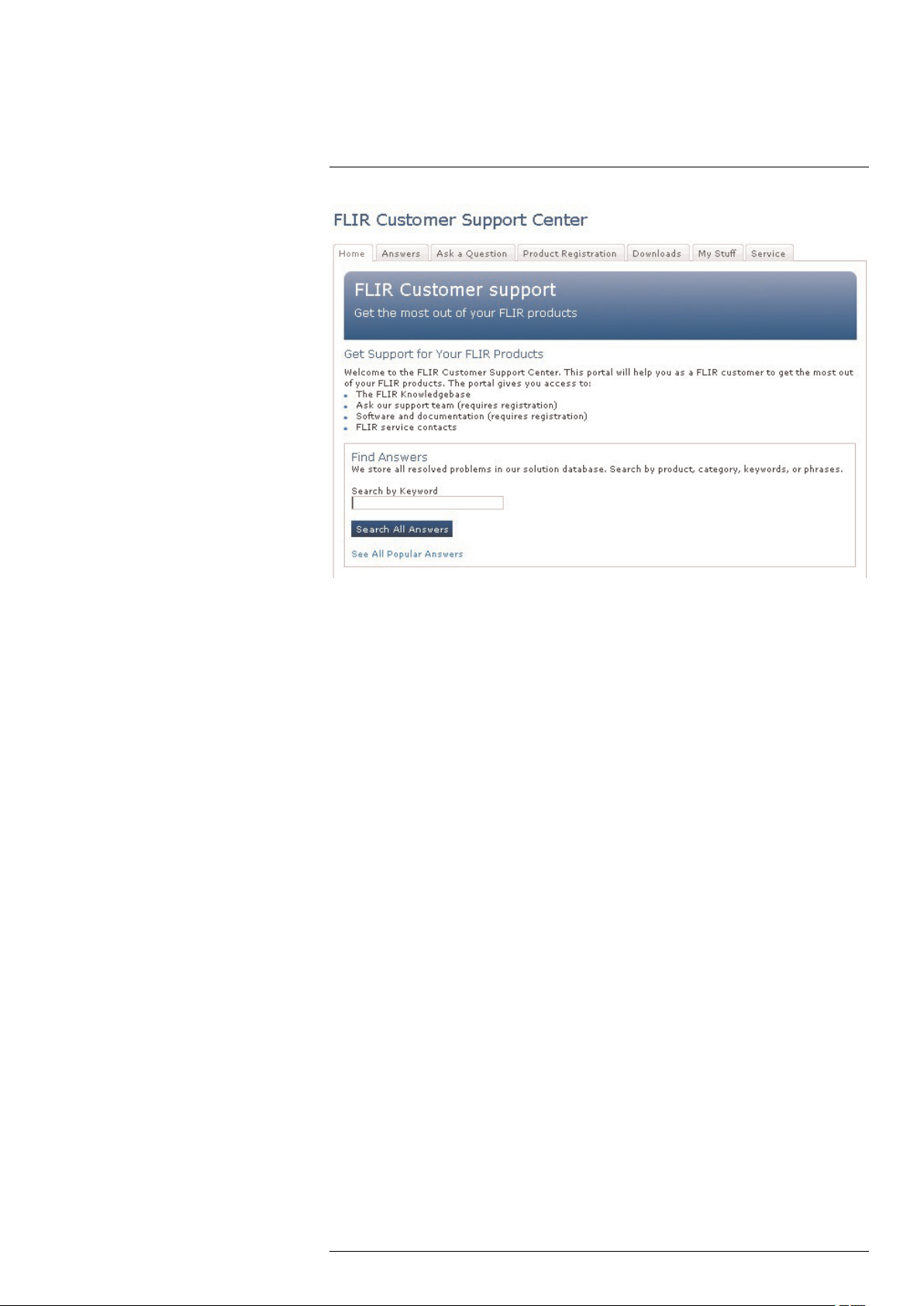
4.1 General
For customer help, visit:
http://support.flir.com
4.2 Submitting a question
To submit a question to the customer help team, you must be a registered user. It only
takes a few minutes to register online. If you only want to search the knowledgebase for
existing questions and answers, you do not need to be a registered user.
When you want to submit a question, make sure that you have the following information
to hand:
• The camera model
• The camera serial number
• The communication protocol, or method, between the camera and your device (for example, HDMI, Ethernet, USB, or FireWire)
• Device type (PC/Mac/iPhone/iPad/Android device, etc.)
• Version of any programs from FLIR Systems
• Full name, publication number, and revision number of the manual
4.3 Downloads
On the customer help site you can also download the following:
• Firmware updates for your infrared camera.
• Program updates for your PC/Mac software.
• Freeware and evaluation versions of PC/Mac software.
• User documentation for current, obsolete, and historical products.
• Mechanical drawings (in *.dxf and *.pdf format).
• Cad data models (in *.stp format).
• Application stories.
• Technical datasheets.
• Product catalogs.
#T559598; r. AB/ 9443/9443; en-US
6
Page 17

5
Parts lists
5.1 Scope of delivery
• Infrared camera with lens
• Battery (2 ea.)
• Battery charger
• Bluetooth headset*
• Calibration certificate
• Downloads brochure
• FLIR ResearchIR scratchcard*
• FLIR Tools download card*
• FLIR apps card
• Getting started guide
• HDMI-DVI cable
• HDMI-HDMI cable
• Hard transport case
• Important information guide
• Large eyecap
• Lens cap
• Memory card with adapter
• Neck strap
• Optics brochure
• Power supply, incl. multi-plugs
• Service & training brochure
• Thank you card
• Tripod adapter
• USB cable, Std A to Mini-B
• User documentation CD-ROM
• Warranty extension card
* The inclusion of this item is dependent on model.
Note
FLIR Systems reserves the right to discontinue models, parts or accessories, and other items, or to
change specifications at any time without prior notice.
5.2 List of accessories and services
Part No Product name
1124544 Neck strap
1910423
1910490
19250-100 IR Window 2 in
19251-100 IR Window 3 in.
19252-100 IR Window 4 in.
APP-10002 FLIR Tools Mobile (Android Application)
APP-10003 FLIR Tools Mobile (iPad/iPhone Application)
DSW-10000 FLIR IR Camera Player
ITC-ADV-3011 ITC Advanced Building – attendance 1 pers
ITC-ADV-3019 ITC Advanced Building – group of 10 pers.
ITC-ADV-3021 ITC Advanced General Thermography Course - attendance, 1 pers.
ITC-ADV-3029 ITC Advanced General Thermography Course- group of 10 pers.
ITC-ADV-3061 ITC Advanced Thermal applications course - attendance 1 pers. (3 days)
ITC-ADV-3069 ITC Advanced Thermal applications course - group up to 10 pers. (3 days)
ITC-CER-5101 ITC Level 1 Thermography Course - attendance, 1 pers.
USB cable Std A <-> Mini-B
Cigarette lighter adapter kit, 12 VDC, 1.2 m/3.9 ft.
#T559598; r. AB/ 9443/9443; en-US
7
Page 18

5
Parts lists
Part No Product name
ITC-CER-5105 ITC Level 1 Thermography Course - additional student to on site class, 1 pers
ITC-CER-5109 ITC Level 1 Thermography Course – group of 10 pers.
ITC-CER-5201 ITC Level 2 Thermography Course - attendance, 1 pers.
ITC-CER-5205 ITC Level 2 Thermography Course - additional student to on site class, 1 pers
ITC-CER-5209 ITC Level 2 Thermography Course – group of 10 pers.
ITC-CER-6101 EN473 IT Certification course Category 1, excl. Certification, 1 pers.
ITC-CER-6109 EN473 IT Certification course Category 1, excl. Certification, group up to 10 pers.
ITC-CON-1001 ITC conference fee
ITC-EXP-0511 ITC Getting Started with Thermography - attendance, 1 pers.
ITC-EXP-0521 ITC Getting Started with Thermography (evening or weekend) - attendance, 1
pers.
ITC-EXP-1001 ITC Training 1 day - attendance 1 pers.
ITC-EXP-1009 ITC Training 1 day - group up to 10 pers.
ITC-EXP-1011 ITC Short course Introduction to thermography -attendance 1 pers. (1 day)
ITC-EXP-1019 ITC Short course Introduction to thermography - inclusive 10 pers. (1 day)
ITC-EXP-1021 ITC In-house training - additional attendance 1 pers. (per day)
ITC-EXP-1029 ITC In-house training - group up to 10 pers. (per day)
ITC-EXP-2001 ITC Training 2 days - attendance 1 pers.
ITC-EXP-2009 ITC Training 2 days - group up to 10 pers.
ITC-EXP-2011 ITC Short course building thermography -attendance 1 pers. (2 days)
ITC-EXP-2019 ITC Short course building thermography - inclusive 10 pers. (2 days)
ITC-EXP-2041 ITC Short course electrical thermography - attendance 1 pers. (2 days)
ITC-EXP-2049 ITC Short course electrical thermography - inclusive 10 pers. (2 days)
ITC-EXP-2061 ITC Short course HVAC and plumbing - attendance 1 pers (2 days)
ITC-EXP-2069 ITC Short course HVAC and plumbing - group up to 10 pers (2 days)
ITC-EXP-3001 ITC Training 3 days - attendance 1 pers.
ITC-EXP-3009 ITC Training 3 days - group up to 10 pers.
ITC-FEE-0120 Certification EN473 IT Category 1
ITC-FEE-0130 Repeat Certification EN473 IT Category 1
ITC-PRA-2011 ITC Practical Course - Solar panel inspection - attendance, 1 pers (2 days)
ITC-PRA-2019 ITC Practical Course - Solar panel inspection - group up to 10 pers (2 days)
ITC-SOW-0001 ITC Software course - attendance 1 pers. (per day)
ITC-SOW-0009 ITC Software course - group up to 10 pers. (per day)
ITC-SOW-1001 ITC Training FLIR Software - attendance 1 pers. (1 day)
ITC-SOW-2001 ITC Training FLIR Software - attendance 1 pers. (2 days)
ITC-TFT-0100 ITC travel time for instructor
ITC-TOL-1001 Travel and lodging expenses instructor (Europe, Balcans, Turkey, Cyprus)
ITC-TOL-1002 Travel and lodging expenses instructor (Russia/GUS, Middle East, North Africa)
ITC-TOL-1003 Travel and lodging expenses instructor (Center and South Africa)
ITC-TOL-1004 Travel and lodging expenses instructor (various)
ITC-TOL-1005 Travel and lodging expenses instructor (other)
T127451 FLIR Reporter Professional (license only)
T127597 FLIR ResearchIR 3 (license only)
#T559598; r. AB/ 9443/9443; en-US
8
Page 19

5
Parts lists
Part No Product name
T127597L10 FLIR ResearchIR 3 (license only), 10 user licenses
T127597L5 FLIR ResearchIR 3 (license only), 5 user licenses
T127598 FLIR ResearchIR 3 Max (license only)
T127598L10 FLIR ResearchIR 3 Max (license only), 10 user licenses
T127598L5 FLIR ResearchIR 3 Max (license only), 5 user licenses
T127648 FLIR Tools+ (license only)
T197717 FLIR Reporter Professional (DVD)
T197731 Tripod Adapter
T197753 Stylus pen
T197771 Bluetooth Headset
T197883 Large eyecap
T197896 High temp option +300°C to 2000°C (+572°F to 3632°F) for FLIR A6xxsc and
T197914 IR lens, f=41.3 mm (15°) with case
T197915 IR lens, f=13.1 mm (45°) with case
T197922 IR lens, f=24.6 mm (25°) with case
T197924 Hard transport case for T6xx series
T197965 FLIR Tools
T198055 Battery
T198059
T198060
T198065 IR lens, f=6.5 mm (80°) with case
T198126 Battery charger, incl. power supply with multi plugs T6xx
T198166 IR lens, f=88.9 mm (7°) with case and support for T6xx
T198206
T198209
T198290 Upgrade FLIR ResearchIR 3 to FLIR ResearchIR 3 Max
T198291 Upgrade previous version to FLIR ResearchIR 3 Max
T198292 Upgrade previous version to FLIR ResearchIR 3
T199836
T199838 Calibration including General maintenance T6xx series
T910737 Memory card micro-SD with adapters
T910814 Power supply, incl. multi plugs
T910891 HDMI type C to HDMI type A cable 1.5 m
T910930 HDMI type C to DVI cable 1.5 m
T910972
T910973
T911048 Pouch for FLIR T6xx and T4xx series
T911093 Tool belt
T6xx
Close-up IR lens, 2.9× (50 µm) with case
Close-up IR lens, 5.8× (100 µm) with case
FLIR ResearchIR 3 (CD)
FLIR ResearchIR 3 Max (CD)
One year extended warranty for T6xx series
EX845: Clamp meter + IR therm TRMS 1000A AC/DC
MO297: Moisture meter, pinless with memory
Note
FLIR Systems reserves the right to discontinue models, parts or accessories, and other items, or to
change specifications at any time without prior notice.
#T559598; r. AB/ 9443/9443; en-US
9
Page 20

6
Quick Start Guide
6.1 Procedure
Follow this procedure:
1. Put a battery into the battery compartment.
2. Charge the battery for 4 hours before starting the camera for the first time, or until the
green battery condition LED glows continuously.
3. Insert a memory card into a card slot.
4. Push the
5. Aim the camera towards the object of interest.
6. Autofocus the camera by pushing the Autofocus/Save button half-way down.
7. Push the Autofocus/Save button fully down to save an image directly.
Note
Whether or not the image will be saved directly depends on the functionality of the Autofocus/Save
button. The functionality can be changed on the Preferences tab (Mode > Settings > Preferences).
8. Do one of the following:
• Remove the memory card and insert it in a card reader connected to a computer.
• Connect a computer to the camera using a USB mini-B cable.
9. Move the image from the card or camera, using a drag-and-drop operation.
Note
You can also move the images to the computer using FLIR Tools, which comes with your camera.
In FLIR Tools you can analyze the images and create PDF reports.
button to turn on the camera.
#T559598; r. AB/ 9443/9443; en-US
10
Page 21
7
A note about ergonomics
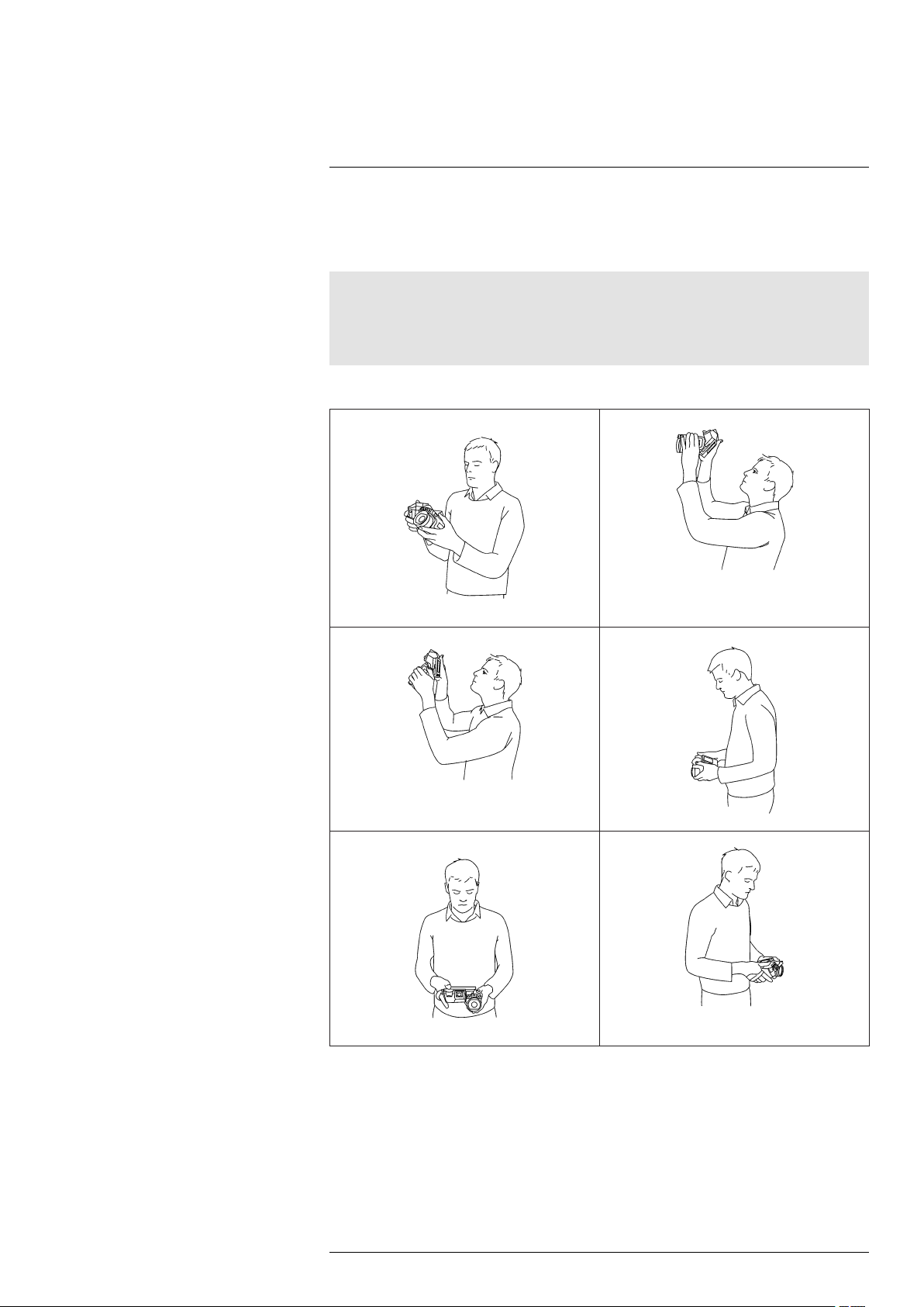
7.1 General
To prevent strain-related injuries, it is important that you hold the camera ergonomically
correct. This section gives advice and examples on how to hold the camera.
Note
Please note the following:
• Always tilt the touch-screen LCD to suit your work position.
• When you hold the camera, make sure that you support the optics housing with your left hand too.
This decreases the strain on your right hand.
7.2 Figure
#T559598; r. AB/ 9443/9443; en-US
11
Page 22
8
Camera parts
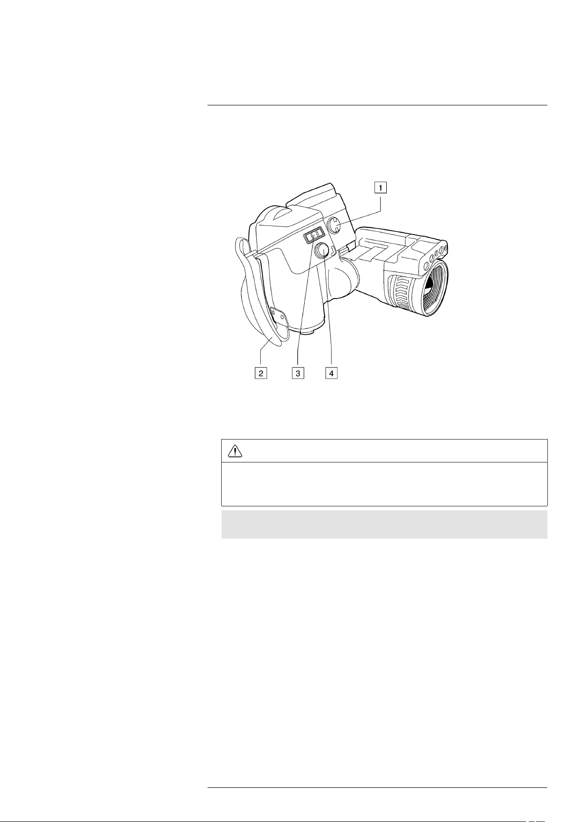
8.1 View from the right
8.1.1 Figure
8.1.2 Explanation
1. Knob to change the dioptric correction for the viewfinder.
CAUTION
Applicability: Cameras with a viewfinder.
Make sure that the beams from the intensive energy sources do not go into the viewfinder. The
beams can cause damage to the camera. This includes the devices that emit laser radiation, or the
sun.
Note
This item is subject to camera model.
2. Handstrap.
3. Digital zoom button.
4. Autofocus/Save button.
#T559598; r. AB/ 9443/9443; en-US
12
Page 23
8
Camera parts
8.2 View from the left
8.2.1 Figure
8.2.2 Explanation
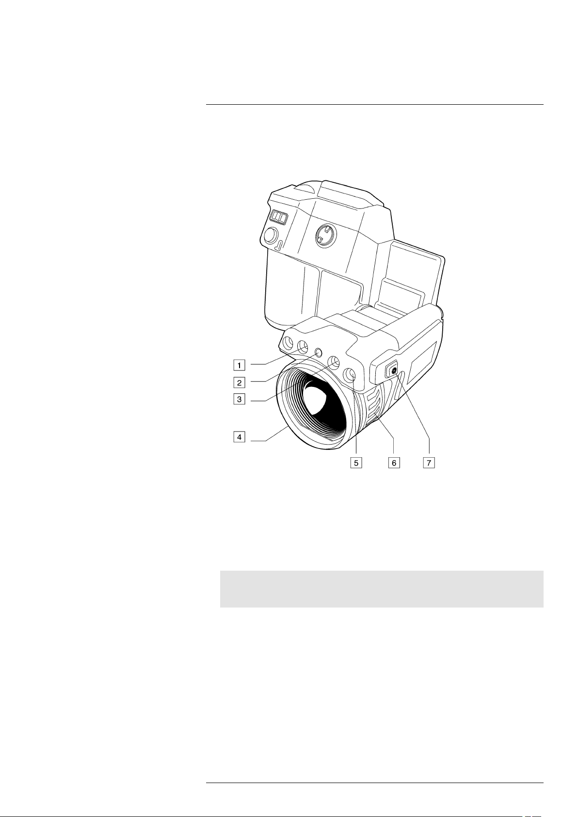
1. Lamp for the digital camera.
2. Laser pointer.
3. Lamp for the digital camera.
4. Infrared lens.
5. Digital camera.
Note
The digital camera can be configured to capture digital photos at the same field of view as the infrared camera. For more information, see 23 Changing settings, page 61.
6. Focus ring.
7. Button to operate the laser pointer.
#T559598; r. AB/ 9443/9443; en-US
13
Page 24
8
Camera parts
8.3 View from the rear
8.3.1 Figure
8.3.2 Explanation
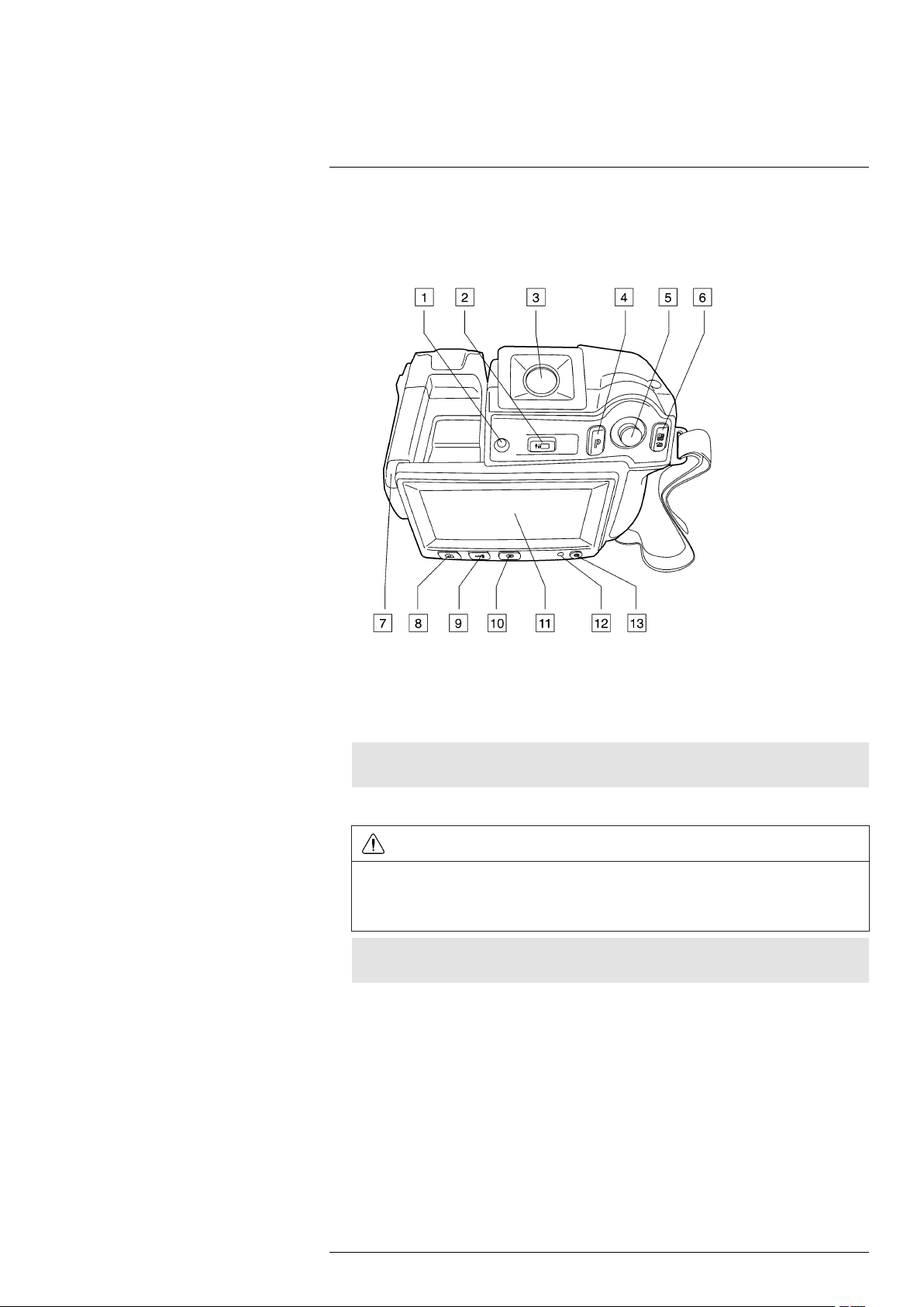
1. Sensor that adjusts the touch-screen LCD intensity automatically.
2. Button to switch between touch-screen LCD mode and viewfinder mode.
Note
This item is subject to camera model.
3. Viewfinder.
CAUTION
Applicability: Cameras with a viewfinder.
Make sure that the beams from the intensive energy sources do not go into the viewfinder. The
beams can cause damage to the camera. This includes the devices that emit laser radiation, or the
sun.
Note
This item is subject to camera model.
4. Programmable button.
5. Joystick with push-button functionality.
6.
• Button to display the menu system.
• Back button.
7. Stylus pen
8. Button to switch between different image modes:
• Infrared camera.
• Digital camera.
• Thermal fusion.
• Picture-in-picture.
• MSX.
#T559598; r. AB/ 9443/9443; en-US
14
Page 25
8
Camera parts
9. Button to switch between automatic mode, manual mode, manual minimum mode,
and manual maximum mode.
10. Image archive.
11. Touch-screen LCD.
12. Power indicator.
13. On/off button.
8.4 View from the bottom
8.4.1 Figure
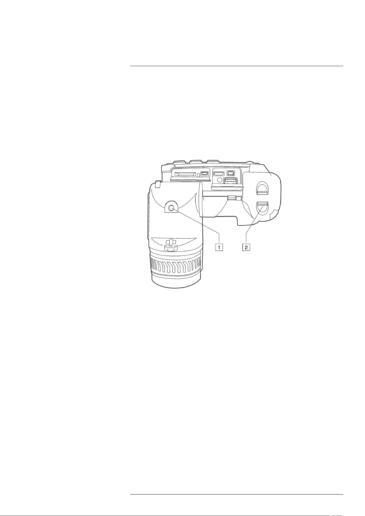
8.4.2 Explanation
1. Tripod mount. Requires an adapter (included).
2. Latch to release the battery.
#T559598; r. AB/ 9443/9443; en-US
15
Page 26
8
Camera parts
8.5 Battery condition LED indicator
8.5.1 Figure
8.5.2 Explanation
Type of signal Explanation
The green LED flashes two times per second. The battery is being charged.
The green LED glows continuously. The battery is fully charged.
8.6 Power LED indicator
8.6.1 Figure
8.6.2 Explanation
Type of signal Explanation
The LED is off. The camera is off.
The LED is blue. The camera is on.
#T559598; r. AB/ 9443/9443; en-US
16
Page 27

8
Camera parts
8.7 Laser pointer
8.7.1 Figure
Figure 8.1 This figure shows the difference in position between the laser pointer and the optical center of
the infrared lens.
WARNING
Do not look directly into the laser beam. The laser beam can cause eye irritation.
CAUTION
Protect the laser pointer with the protective cap when you are not using the laser pointer.
Note
The symbol
Note
The laser pointer may not be enabled in all markets.
is displayed on the screen when the laser pointer is on.
8.7.2 Laser warning label
A laser warning label with the following information is attached to the camera:
8.7.3 Laser rules and regulations
Wavelength: 635 nm. Maximum output power: 1 mW.
This product complies with 21 CFR 1040.10 and 1040.11 except for deviations pursuant
to Laser Notice No. 50, dated June 24, 2007.
#T559598; r. AB/ 9443/9443; en-US
17
Page 28
9
Screen elements
9.1 Main screen area
9.1.1 Figure
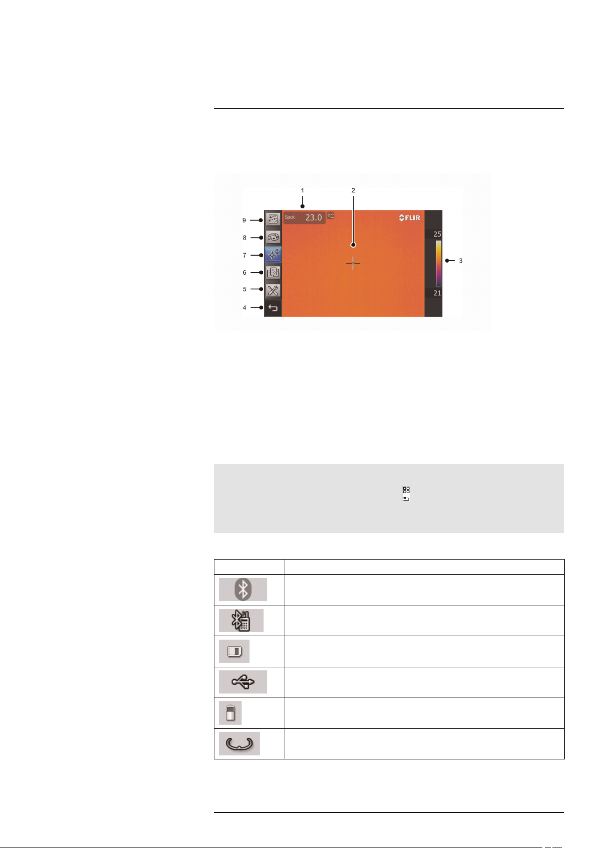
9.1.2 Explanation
1. Measurement result table.
2. Measurement tools (e.g., spotmeter).
3. Temperature scale.
4. Back button.
5. Mode button (camera, video, program, settings).
6. Predefined sets of measurement tools.
7. Measurement tools.
8. Color palettes.
9. Measurement parameters.
Note
• To display the menu system, tap the screen or push
• Additional information and icons may be displayed on the screen, depending on functionality and
visibility, e.g. compass and GPS data (see 23 Changing settings, page 61).
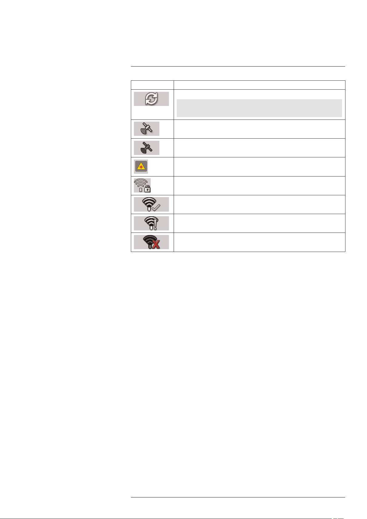
9.2 Status icons and indicators
Icon or indicator Explanation
The camera’s Bluetooth connectivity is enabled.
The camera’s Bluetooth connectivity is enabled and the camera is connected to
an Extech meter, using MeterLink.
.
Memory card indicator.
The camera is connected to a device using USB.
Battery status indicator.
Compass indicator
#T559598; r. AB/ 9443/9443; en-US
18
Page 29
9
Screen elements
Icon or indicator Explanation
The internal database managing images is out of sync.
Note
You need to tap this icon when it appears in the top right corner of the screen.
GPS connection is OK.
Scanning for GPS satellites.
Laser notification.
Protected WLAN (WEP, WPA)
The camera is connected to the WLAN.
The camera failed to connect to the WLAN.
WLAN error.
#T559598; r. AB/ 9443/9443; en-US
19
Page 30
10
Navigating the menu system
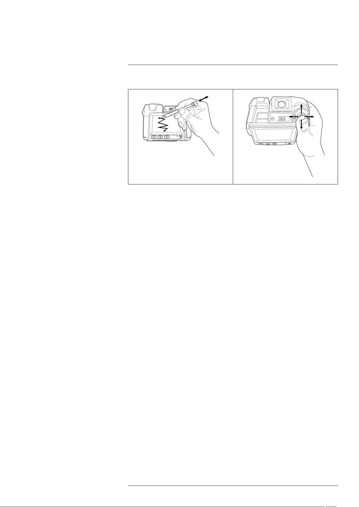
10.1 Figure
10.2 Explanation
The figure above shows the two ways to navigate the menu system in the camera:
• Using the index finger or the stylus pen to navigate the menu system (left).
• Using the joystick to navigate the menu system (right).
#T559598; r. AB/ 9443/9443; en-US
20
Page 31

11
Connecting external devices and storage media
11.1 Figure
11.2 Explanation
1. Memory card.
2. Indicator showing that the memory card is busy.
Note
• Do not eject the SD memory card when this LED is flashing.
• Do not connect the camera to a computer when this LED is flashing.
3. USB mini-B cable (to connect the camera to a PC).
4. HDMI cable.
5. Power cable.
6. USB-A cable.
#T559598; r. AB/ 9443/9443; en-US
21
Page 32

12
Pairing Bluetooth devices
12.1 General
Before you can use a Bluetooth device with the camera, you need to pair the devices.
12.2 Procedure
Follow this procedure:
1. Go to
2. Go to the Connectivity tab.
3. Activate Bluetooth.
Note
You also need to activate Bluetooth connectivity on the external device.
4. Select Add Bluetooth device.
5. Select Scan for Bluetooth device, and wait until a list of available devices is displayed.
This will take about 15 seconds.
6. When a Bluetooth device is found, select the device to add it. The device is now
ready to be used.
Note
• You can add several devices.
• You can remove an added device by selecting the device and and then selecting Remove.
• After adding a MeterLink device, such as the Extech MO297 or EX845, the result from the meter will
be visible in the measurement result table.
• After adding a Bluetooth-enabled headset, it is ready to be used in camera preview mode.
• It is also possible to add live snapshot values from MeterLink devices in preview mode.
(Mode) and then choose Settings.
#T559598; r. AB/ 9443/9443; en-US
22
Page 33

13
Configuring Wi-Fi
13.1 General
Depending on your camera configuration, you can connect the camera to a wireless local
area network (WLAN) using Wi-Fi, or let the camera provide Wi-Fi access to another
device.
You can connect the camera in two different ways:
• Most common use: Setting up a peer-to-peer connection (also called ad hoc or P2P
connection). This method is primarily used with other devices, e.g., an iPhone or iPad.
• Less common use: Connecting the camera to a WLAN.
13.2 Setting up a peer-to-peer connection (most common use)
Follow this procedure:
1. Go to
2. Go to the Connectivity tab.
3. Under Wi-Fi, select Connect device.
4. Select Wi-Fi settings.
5. Enter values for the following parameters:
• SSID (the name of the network).
• Channel (the channel that the other device is broadcasting on).
• Encryption (the encryption algorithm, e.g., None or WEP).
• Key (the access key to the network).
• Address (the IP address for the network).
• Gateway (the gateway IP address for the network).
Note
These parameters are set for your camera's network. They will be used by the external device to
connect that device to the network.
6. Push the joystick to confirm the choice.
13.3 Connecting the camera to a wireless local area network (less common use)
Follow this procedure:
1. Go to
2. Go to the Connectivity tab.
3. Under Wi-Fi, select Connect to WLAN.
4. Select Wi-Fi settings.
5. Select one of the available networks.
Password-protected networks are indicated with a padlock icon, and for these you
will need to enter an access key.
6. Push the joystick to confirm the choice.
(Mode) and then choose Settings.
(Mode) and then choose Settings.
Note
Some networks do not broadcast their existence. To connect to such a network, select Add manually
and set all parameters manually according to that network.
#T559598; r. AB/ 9443/9443; en-US
23
Page 34

14
Handling the camera
14.1 Charging the battery
Note
You must charge the battery for four hours before you start using the camera for the first time.
14.1.1 Using the power supply to charge the battery
14.1.1.1 Procedure
Follow this procedure:
1. Connect the power supply cable plug to the power connector on the camera.
2. Connect the power supply mains-electricity plug to a mains socket.
3. Disconnect the power supply cable plug when the green light of the battery condition
LED indicator is continuous.
14.1.2 Using the stand-alone battery charger to charge the battery
14.1.2.1 Explanation
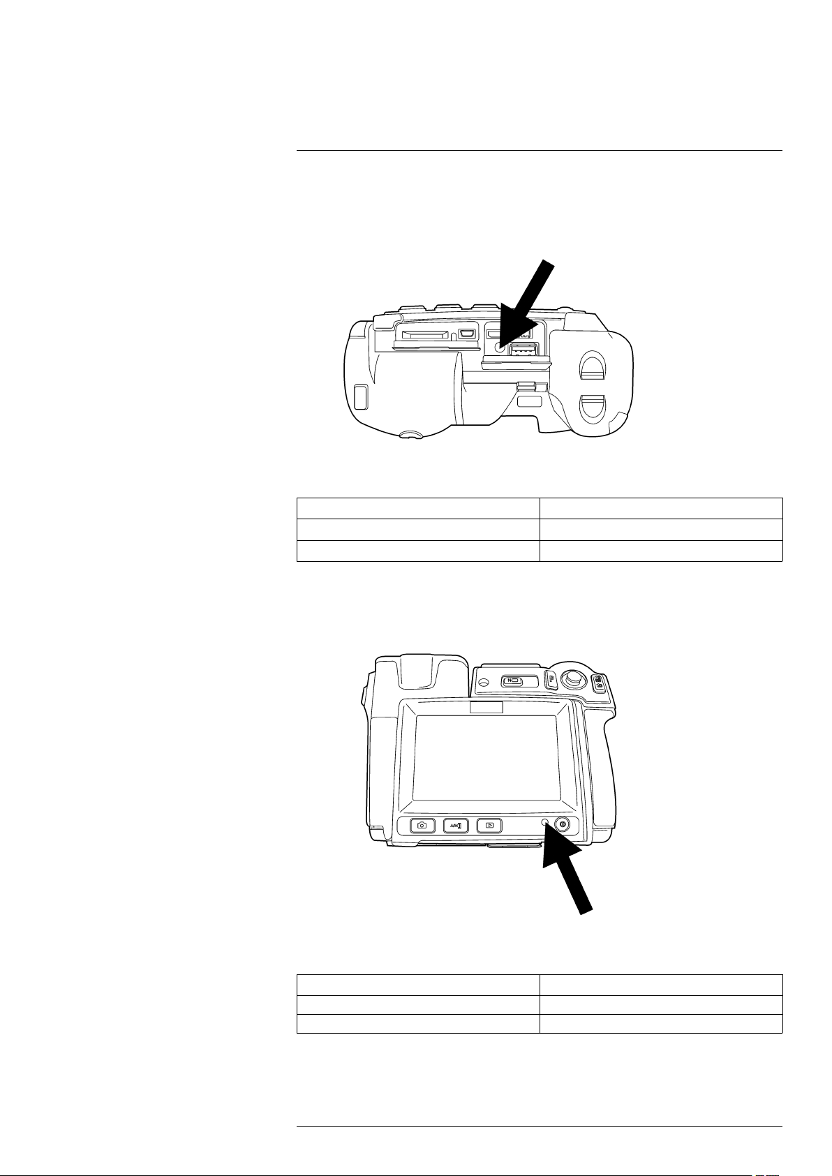
Type of signal Explanation
The blue LED flashes. The battery is being charged.
The blue LED glows continuous. The battery is fully charged.
14.1.2.2 Procedure
Follow this procedure:
1. Put the battery in the battery charger.
2. Connect the power supply cable plug to the connector on the battery charger.
3. Connect the power supply mains-electricity plug to a mains socket.
4. Disconnect the power supply cable plug when the blue LED on the battery charger is
continuous.
14.2 Turning on the camera
14.2.1 Procedure
Follow this procedure:
1. To turn on the camera, push and release the
14.3 Turning off the camera
14.3.1 Procedure
Follow this procedure:
1. To turn off the camera, push and hold the
button.
button for more than 0.2 second.
#T559598; r. AB/ 9443/9443; en-US
24
Page 35

Handling the camera14
14.4 Adjusting the viewfinder’s dioptric correction
14.4.1 Figure
CAUTION
Applicability: Cameras with a viewfinder.
Make sure that the beams from the intensive energy sources do not go into the viewfinder. The beams
can cause damage to the camera. This includes the devices that emit laser radiation, or the sun.
Note
This item is subject to camera model.
14.4.2 Procedure
Follow this procedure:
1. To adjust the viewfinder’s dioptric correction, look at the displayed text or graphics on
the screen, and rotate the adjustment knob clockwise or counter-clockwise for best
sharpness.
Note
• Maximum dioptric correction: +2.
• Minimum dioptric correction: –2.
#T559598; r. AB/ 9443/9443; en-US
25
Page 36

Handling the camera14
14.5 Adjusting the angle of the lens
14.5.1 Figure
14.6 Adjusting the infrared camera focus manually
14.6.1 Figure
14.6.2 Procedure
Follow this procedure:
1. Do one of the following:
• For far focus, rotate the focus ring clockwise (looking at the touch-screen LCD
side).
• For near focus, rotate the focus ring counter-clockwise (looking at the touchscreen LCD side).
#T559598; r. AB/ 9443/9443; en-US
26
Page 37

Handling the camera14
Note
• Do not touch the lens surface when you adjust the infrared camera focus manually. If this happens,
clean the lens according to the instructions in 27.2 Infrared lens, page 74.
• The focus ring can be rotated infinitely, but only a certain amount of rotation is needed when
focusing.
14.7 Autofocusing the infrared camera
14.7.1 Figure
14.7.2 Procedure
Follow this procedure:
1. To autofocus the camera, push the Autofocus/Save button half-way down.
14.8 Continuous autofocus
14.8.1 General
The camera can be set up to perform a continuous autofocusing sequence. In this mode,
a small frame is displayed on the screen and the camera will continuously autofocus any
object that is within this frame.
14.8.2 Procedure
Follow this procedure:
1. Push
2. Use the joystick to go to
to display the menu system.
(Mode).
3. Push the joystick. This will display a Mode menu.
4. On the Mode menu, select Settings and push the joystick.
5. On the Camera tab, select Continuous auto focus and push the joystick to enable
continuous autofocus.
6. Aim the camera towards the object of interest. The camera will now continuously autofocus any object that is within the small frame in the middle of the screen.
#T559598; r. AB/ 9443/9443; en-US
27
Page 38

Handling the camera14
14.9 Operating the laser pointer
14.9.1 Figure
14.9.2 Procedure
Follow this procedure:
1. To turn on the laser pointer, push and hold the laser button.
2. To turn off the laser pointer, release the laser button.
Note
• A warning indicator is displayed on the screen when the laser pointer is turned on.
• The position of the laser dot is indicated on the infrared image (depending on the camera model).
#T559598; r. AB/ 9443/9443; en-US
28
Page 39

Handling the camera14
14.10 Using the digital zoom function
14.10.1 Figure
14.10.2 Procedure
Follow this procedure:
1. To zoom, push the zoom button left or right.
14.11 Changing lenses
Follow this procedure:
1. Take a firm grip around the outermost part of the lens.
#T559598; r. AB/ 9443/9443; en-US
29
Page 40

Handling the camera14
2. Rotate the lense 30° degrees counter-clockwise.
3. Carefully pull out the lens from the lens bayonet mount.
4. The infrared detector is now fully exposed. Do not touch this surface. If you see dust
on the detector, follow the instructions in 27.3 Infrared detector, page 75.
5. Note the index marks on the lens bayonet mount and on the lens.
#T559598; r. AB/ 9443/9443; en-US
30
Page 41

Handling the camera14
6. Align the lens correctly to the bayonet mount.
7. Carefully push the lens into position.
8. Rotate the lens 30° degrees clockwise.
#T559598; r. AB/ 9443/9443; en-US
31
Page 42

Handling the camera14
14.12 Calibrating the compass
14.12.1 Figure
14.12.2 Procedure
Follow this procedure:
1. Push
2. Use the joystick to go to
to display the menu system.
(Mode).
3. Push the joystick. This will display a Mode menu.
4. On the Mode menu, select Settings and push the joystick.
5. Go to the Camera tab.
6. On the Camera tab, select Calibrate compass and push the joystick.
7. Click Start.
8. Calibrate the compass by rotating the camera vertically one revolution and horistontally one revolution.
14.13 Calibrating the touchscreen LCD
14.13.1 Figure
14.13.2 Procedure
Follow this procedure:
1. Push
to display the menu system.
2. Use the joystick to go to
#T559598; r. AB/ 9443/9443; en-US
(Mode).
32
Page 43

Handling the camera14
3. Push the joystick. This will display a Mode menu.
4. On the Mode menu, select Settings and push the joystick.
5. Go to the Camera tab.
6. On the Camera tab, select Calibrate touchscreen and push the joystick.
7. Click Start.
8. Calibrate the touchscreen by tapping the five crosshairs that appear on the screen
using the stylus pen.
14.14 Changing the viewfinder’s eyecap
CAUTION
Applicability: Cameras with a viewfinder.
Make sure that the beams from the intensive energy sources do not go into the viewfinder. The beams
can cause damage to the camera. This includes the devices that emit laser radiation, or the sun.
Note
This item is subject to camera model.
Follow this procedure:
1. Take a firm grip around the uppermost part of the eyecap.
2. Pull out the eyecap from its mount.
3. Note the grooves on the eyecap and the eyecap mount.
#T559598; r. AB/ 9443/9443; en-US
33
Page 44

Handling the camera14
4. Align the eyecap to the eyecap mount.
5. Push down the eyecap into position.
#T559598; r. AB/ 9443/9443; en-US
34
Page 45

15
Working with images
15.1 Saving an image
15.1.1 General
You can save an image directly, without previewing the image first.
15.1.2 Image capacity
This table gives information on the approximate number of infrared (IR) and digital camera (DC) images that can be saved on memory cards:
Card size
1 GB
2 GB
IR only
1450 600 450
2900 1200 900
IR + DC
15.1.3 Naming convention
The naming convention for images is one of the following:
• IR_xxxx.jpg, where xxxx is a unique counter.
• Date.
IR + DC + 30 seconds
voice annotation
15.1.4 Procedure
Follow this procedure:
1. To save an image directly, push the Autofocus/Save button.
Note
You can change the function of the Autofocus/Save button under
ces. The function can be set to one of the following:
• Preview/Save (Brief depression = Preview; Long depression = Save).
• Save directly (default setting)
• Always preview
(Mode) > Settings > Preferen-
15.2 Previewing an image
15.2.1 General
You can preview an infrared image (full infrared, fusion, picture-in-picture) or a digital
photo before you save it to a memory card. This enables you to see if the image or photo
contains the information you want before you save it.
In preview mode, you can also manipulate the image before you save it, and add annotations in order to simplify report generation.
15.2.2 Procedure
Follow this procedure:
1. To preview an image, briefly push and release the Autofocus/Save button.
Note
This is not the default setting of the camera and requires that you change the behavior of the button. See below for instructions.
#T559598; r. AB/ 9443/9443; en-US
35
Page 46

Working with images15
Note
You can change the function of the Autofocus/Save button under
ces. The function can be set to one of the following:
• Preview/Save (Brief depression = Preview; Long depression = Save).
• Save directly (default setting)
• Always preview
(Mode) > Settings > Preferen-
15.3 Opening an image
15.3.1 General
When you save an image, the image is stored on a memory card. To display the image
again, open it from the memory card.
15.3.2 Procedure
Follow this procedure:
1. Push
.
2. Push the joystick up/down or left/right to select the image you want to view.
3. Push the joystick. This will display the image at full size.
4.
Do one of the following:
• To edit the opened image, push the joystick, which will bring up a menu.
• Move left/right to view the previous/next image.
• Push
to return to the image overview.
15.4 Adjusting an infrared image
15.4.1 General
An infrared image can be adjusted automatically or manually. You use the
button
to switch between these two modes. Note that this only works in live mode and not in
preview/archive mode.
15.4.2 Example 1
This figure shows two infrared images of cable connection points. In the left image, a correct analysis of the circled cable is difficult if you only auto-adjust the image. You can analyze this cable in more detail if you:
• Change the temperature scale level.
• Change the temperature scale span.
In the left image, the image is auto-adjusted. In the right image, the maximum and mini-
mum temperature levels have been changed to temperature levels near the object. On
the temperature scale to the right of each image you can see how the temperature levels
were changed.
#T559598; r. AB/ 9443/9443; en-US
36
Page 47

Working with images15
15.4.3 Example 2
This figure shows two infrared images of an isolator in a power line.
In the left image, the cold sky and the power line structure are recorded at a minimum
temperature of –26.0°C (–14.8°F). In the right image, the maximum and minimum temperature levels have been changed to temperature levels near the isolator. This makes it
easier to analyze the temperature variations in the isolator.
15.4.4 Changing the temperature scale level
Follow this procedure:
1. Push
2. Use the joystick to select
.
Manual.
3. To change the scale level, push the joystick up/down.
4. (Optional step.)
Do one of the following:
• Push the joystick to perform an one-shot auto-adjust sequence.
• Push
again and select Auto to return to automatic mode.
15.4.5 Changing the temperature scale span
Follow this procedure:
1. Push
2. Use the joystick to select
.
(Manual).
3. To change the scale span, push the joystick left/right.
15.5 Hiding overlay graphics (programmable button)
15.5.1 General
Overlay graphics provide information about an image, e.g., measurement functions and
parameters. You can choose to hide all overlay graphics.
15.5.2 Procedure
Follow this procedure:
1. Push
2. Use the joystick to go to
to display the menu system.
(Mode).
3. Push the joystick. This will display a Mode menu.
4. On the Mode menu, select Settings and push the joystick.
#T559598; r. AB/ 9443/9443; en-US
37
Page 48

Working with images15
5. Use the joystick to go to (Preferences).
6. Under Programmable button, select Hide graphics. You have now assigned this func-
tion to the
button. This is a programmable button, and you can assign other func-
tions to it.
Note
Other functions that can be associated with the programmable button include the following:
• Hide graphics
• Invert palette
• Switch palette
• Camera
• Adjust image
• Calibrate
• Save
• Preview
• Lamp
• Zoom
• Switch auto focus
15.6 Changing the palette
15.6.1 General
You can change the color palette that the camera uses to display different temperatures.
A different palette can make it easier to analyze an image.
15.6.2 Procedure
Follow this procedure:
1. Push
to display the menu system.
2. Use the joystick to go to
.
3. Push the joystick to display a submenu.
4. Use the joystick to select a different palette.
5. Push the joystick.
15.7 Deleting an image
15.7.1 General
You can delete one or more images.
15.7.2 Procedure
Follow this procedure:
1. Push
.
2. Push the joystick up/down or left/right to select the image you want to delete.
3. Push the joystick to display the image.
4. Push the joystick to display a menu.
5. On the menu, select Delete and confirm the choice.
Note
Note that all images in the same group will be deleted at the same time, e.g., digital photos.
15.8 Deleting all images
15.8.1 General
You can delete all images.
#T559598; r. AB/ 9443/9443; en-US
38
Page 49

Working with images15
15.8.2 Procedure
Follow this procedure:
1. Push
.
2. Push the joystick up/down or left/right to select any image.
3. Push the joystick to display the image.
4. Push the joystick to display a menu.
5. On the menu, select Delete all and confirm the choice.
15.9 Creating a PDF report in the camera
15.9.1 General
You can create a PDF report in the camera. You can then transfer the PDF report to a
computer, iPhone, or iPad using the FLIR Viewer app, and send the report to a customer.
15.9.2 Procedure
Follow this procedure:
1. Push
.
2. Push the joystick up/down or left/right to select an image.
3. Push the joystick to display the image.
4. Push the joystick to display a menu.
5. On the menu, select Create report.
This will display a menu where you can change the following:
• Header.
• Footer.
• Logotype. (The location of the logo should be /report/logo/ on the memory card.
The file format shall be *.jpg. The maximum width shall be 134 pixels for A4 pagesize and 139 pixels for US Letter pagesize.)
6. On the menu, select Create report.
#T559598; r. AB/ 9443/9443; en-US
39
Page 50

16
Working with image modes
16.1 What is picture-in-picture?
Picture-in-picture is similar to thermal fusion in that it lets you display part of a digital photo as an infrared image.
However, picture-in-picture displays an infrared image frame on top of a digital photo.
16.2 What is thermal fusion?
Thermal fusion is a function that lets you display part of a digital photo as an infrared
image.
For example, you can set the camera to display all areas of an image that have a certain
temperature in infrared, with all other areas displayed as a digital photo.
16.3 Types
The number of image modes is subject to camera models. These include:
• Above: All areas in the digital photo with a temperature above the specified temperature level are displayed in infrared.
• Below: All areas in the digital photo with a temperature below the specified temperature level are displayed in infrared.
• Interval: All areas in the digital photo with a temperature between two specified temperature levels are displayed in infrared.
• Picture-in-Picture: An infrared image frame is displayed on top of the digital photo.
• MSX (Multi Spectral Dynamic Imaging): Using this mode, the camera captures infrared images where the edges of the objects are enhanced.
Note
These image modes only work correctly for calibrated lenses. The lens that ships with the camera is
factory-calibrated. To have a new lens calibrated, your must send in the camera and the lens to your local service department.
16.4 Image examples
This table explains the different types.
Type Image
Above
Below
#T559598; r. AB/ 9443/9443; en-US
40
Page 51

Working with image modes16
Type Image
Interval
Picture-in-Picture
MSX
16.5 Setting up Thermal fusion
Follow this procedure:
1. Push
2. On the toolbar, select
3. Push
to display a toolbar.
(Thermal fusion).
.
4. To change the portion of infrared in the image, do one of the following:
• Push the joystick left/right to select
, then push the joystick up/down to change
the bottom temperature level.
• Push the joystick left/right to select
, then push the joystick up/down to change
the top temperature level.
• Push the joystick left/right to select
, then push the joystick up/down to change
the top and bottom temperature level at the same time, and left/right to change the
temperature span.
#T559598; r. AB/ 9443/9443; en-US
41
Page 52

Working with image modes16
Note
How to use thermal fusion in manual mode is described above.
When using thermal fusion in automatic mode, the temperature levels for the thermal fusion will be
based on the temperature levels inside the aiming frame that is displayed in the middle of the image.
16.6 Setting up picture-in-picture
Follow this procedure:
1. Push
2. On the toolbar, select
to display a toolbar.
(Picture-in-Picture)
This will display an infrared image frame on top of a digital photo. At this point you
can move and resize the image frame using the touchscreen LCD.
16.7 Setting up MSX
Follow this procedure:
1. Push
2. On the toolbar, select
to display a toolbar.
(MSX).
#T559598; r. AB/ 9443/9443; en-US
42
Page 53

17
Working with measurement tools
17.1 Laying out measurement tools: spots, areas, etc.
17.1.1 General
To measure a temperature, you use one or more measurement tools, e.g., a spotmeter
or a box.
17.1.2 Procedure
Follow this procedure:
1. Push
2. Use the joystick to go to
3. Push the joystick to display a submenu.
4. Use the joystick to go to a measurement tool.
5. Push the joystick. This will display the measurement tool on the screen.
17.2 Laying out measurement tool: isotherms
17.2.1 General
The isotherm command applies a contrasting color to all pixels with a temperature
above, below, or between one or more set temperature levels.
Using isotherms is a good method to easily discover anomalies in an infrared image.
17.2.2 Procedure
Follow this procedure:
1. Push
2. Use the joystick to go to
3. Push the joystick to display a submenu.
4. Use the joystick to go to
5. Push the joystick. This will display a submenu.
or tap the screen to display the menu system.
.
or tap the screen to display the menu system.
.
.
#T559598; r. AB/ 9443/9443; en-US
43
Page 54

Working with measurement tools17
6. In the submenu, select one of the following:
• Above. This will apply a contrasting color to all pixels with a temperature above
one or more set temperature levels.
• Below. This will apply a contrasting color to all pixels with a temperature below
one or more set temperature levels.
• Interval. This will apply a contrasting color to all pixels with a temperature between
two or more set temperature levels.
• Humidity. This will apply a contrasting color to all pixels with a temperature below
a threshold calculated by humidity parameters. For more information about this,
see 19 Working with alarms and isotherms, page 50.
• Insulation. This will apply a contrasting color to all pixels with a temperature below
a threshold calculated by insulation parameters. For more information about this,
see 19 Working with alarms and isotherms, page 50.
This will display a flag in the temperature scale. See the image below.
7. To change the temperature level, do one of the following:
• Tap and drag the flag up/down.
• Move the joystick up/down.
17.3 Working with presets
17.3.1 General
A preset is a measurement tool, or a group of measurement tools, with predefined characteristics. By selecting a preset you save time compared to creating each individual
measurement tool, one at a time.
17.3.2 Procedure
Follow this procedure:
1. Push
2. Use the joystick to go to
or tap the screen to display the menu system.
.
3. Push the joystick to display a submenu.
4. Use the joystick to go to a preset.
5. Push the joystick. This will display the preset on the screen.
17.4 Moving or resizing a measurement tool
17.4.1 General
You can move and resize a measurement tool.
17.4.2 Procedure
Note
• This procedure assumes that you have previously laid out a measurement tool on the screen.
• You can also move and resize the measurement tool using the stylus pen.
#T559598; r. AB/ 9443/9443; en-US
44
Page 55

Working with measurement tools17
Follow this procedure:
1. Push
2. Use the joystick to go to
or tap the screen to display the menu system.
(Tools).
3. Push the joystick to display a submenu.
4. Use the joystick to go to
(Adjust tools).
5. Push the joystick and select the measurement tool that you want to move or resize.
6. Push the joystick. The measurement tool will now be displayed with one or more handles, which you use to move or resize the tool.
Figure 17.1 Spot measurement tool.
Figure 17.2 Area measurement tool.
7. Use the joystick to move or resize the measurement tool.
8. Optional step:
Push the joystick, or tap and hold down the finger on the screen to display a context
menu.
17.5 Creating and setting up a difference calculation
17.5.1 General
A difference calculation gives the difference between the values of two known measurement results.
17.5.2 Procedure
Note
This procedure assumes that you have previously laid out at least two measurement tools on the
screen.
Follow this procedure:
1. Push
2. Use the joystick to go to
or tap the screen to display the menu system.
(Tools).
3. Push the joystick to display a submenu.
4. Use the joystick to select
(Add difference).
#T559598; r. AB/ 9443/9443; en-US
45
Page 56

Working with measurement tools17
5.
Push the joystick. This will display a dialog box where you can select the measurement tools that you want to use in the difference calculation.
6. Push the joystick. The result of the difference calculation is now displayed in the result table.
17.6 Changing object parameters
17.6.1 General
For accurate measurements, you must set the object parameters.
17.6.2 Types of parameters
The camera can use these object parameters:
• Emissivity, i.e., how much radiation an object emits, compared with the radiation of a
theoretical reference object of the same temperature (called a “blackbody”). The opposite of emissivity is reflectivity. The emissivity determines how much of the radiation
originates from the object as opposed to being reflected by it.
• Reflected apparent temperature, which is used when compensating for the radiation
from the surroundings reflected by the object into the camera. This property of the object is called reflectivity.
• Object distance, i.e., the distance between the camera and the object of interest.
• Atmospheric temperature, i.e., the temperature of the air between the camera and the
object of interest.
• Relative humidity, i.e., the relative humidity of the air between the camera and the ob-
ject of interest.
• External IR window compensation, i.e., the temperature of any protective windows,
etc., that are set up between the camera and the object of interest. If no protective
window or protective shield is used, this value is irrelevant and should be left inactive.
17.6.3 Recommended values
If you are unsure about the values, the following are recommended:
Emissivity 0.95
Object distance 1.0 m (3.3 ft.)
Reflected apparent temperature +20°C (+69°F)
Relative humidity 50%
Atmospheric temperature +20°C (+69°F)
17.6.4 Procedure
Follow this procedure:
1. Push
2. Use the joystick to go to
or tap the screen to display the menu system.
.
3. Push the joystick to display a dialog box.
4. Use the joystick to select and change an object parameter.
5. Push the joystick. This will close the dialog box.
#T559598; r. AB/ 9443/9443; en-US
46
Page 57

Working with measurement tools17
Note
Of the parameters above, emissivity and reflected apparent temperature are the two most important to
set correctly in the camera.
17.6.5 Related topics
For in-depth information about parameters, and how to correctly set the emissivity and
reflected apparent temperature, see 31 Thermographic measurement techniques, page
86.
#T559598; r. AB/ 9443/9443; en-US
47
Page 58

18
Fetching data from external Extech meters
18.1 General
You can fetch data from an external Extech meter and merge this data into the result table in the infrared image.
18.2 Figure
18.3 Supported Extech meters
• Extech Moisture Meter MO297
• Extech Clamp Meter EX845
18.4 Technical support for Extech meters
support@extech.com
This support is for Extech meters only. For technical support for infrared cameras, go to
http://support.flir.com.
For more information about products from Extech Instruments, go to http://www.extech.
com/instruments/.
18.5 Procedure
Note
This procedure assumes that you have paired the Bluetooth devices and set the functionality of the
Save button to Preview/Save.
Follow this procedure:
1. Turn on the camera.
2. Turn on the Extech meter.
3. On the meter, enable Bluetooth mode. Refer to the user documentation for the meter
for information on how to do this.
4. On the meter, choose the quantity that you want to use (voltage, current, resistance,
etc.). Refer to the user documentation for the meter for information on how to do this.
Results from the meter will now automatically be displayed in the result table in the
top left corner of the infrared camera screen.
#T559598; r. AB/ 9443/9443; en-US
48
Page 59

18
Fetching data from external Extech meters
5. Do one of the following:
• To preview an image, push the Preview/Save button. At this stage, you can add
additional values. To do so, take a new measurement with the meter and select
Add on the infrared camera screen.
• To save an image without previewing, push and hold down the Preview/Save
button.
• (Dependent on camera model) To add a value to a recalled image, turn on the me-
ter after you have recalled the image, then select Add on the infrared camera
screen. A maximum of eight values can be added, but note that some values are
broken into two lines.
6. Click Close or Save (depending on camera model).
18.6 Typical moisture measurement and documentation procedure
18.6.1 General
The following procedure can form the basis for other procedures using Extech meters
and infrared cameras.
18.6.2 Procedure
Follow this procedure:
1. Use the infrared camera to identify any potential damp areas behind walls and
ceilings.
2. Use the moisture meter to measure the moisture levels at various suspect locations
that may have been found.
3. When a spot of particular interest is located, store the moisture reading in the moisture meter’s memory and identify the measurement spot with a handprint or other
thermal identifying marker.
4. Recall the reading from the meter memory. The moisture meter will now continuously
transmit this reading to the infrared camera.
5. Use the camera to take a thermal image of the area with the identifying marker. The
stored data from the moisture meter will also be saved on the image.
#T559598; r. AB/ 9443/9443; en-US
49
Page 60

19
Working with alarms and isotherms
19.1 Measurement alarms
19.1.1 General
You can make the camera trigger an audible alarm when certain measurement conditions are met.
19.1.2 Types of alarm
You can choose between the following alarm types:
• Above: Triggers an alarm when a temperature is above the preset alarm temperature.
• Below: Triggers an alarm when a temperature is below the preset alarm temperature.
19.1.3 Alarm signals
When an alarm is triggered, an audible alarm signal will sound (a ‘beep’).
19.1.4 Procedure
Note
This procedure is an example procedure about setting up an alarm for a spotmeter temperature. Setting up alarms for other measurement tools works in a similar way.
Follow this procedure:
1. Push
2. Use the joystick to go to
3. Push the joystick to display a submenu.
4. Use the joystick to go
5. Push the joystick to display a list of active measurement tools.
6. Select Spot and push the joystick. This will display a Spot menu.
7. On the Spot menu, enable Alarm.
8. On the Spot menu, go to Alarm settings and push the joystick. This display an Alarm
settings menu.
9. On the Alarm settings menu, set the following:
• Condition: The condition that triggers the alarm. Applicable values are Above or
• Threshold: The temperature value that shall be the critical condition when an
• Beep: The audible alarm signal.
19.2 Building isotherms
19.2.1 General
The camera features isotherm types that are specific to the building trade. You can make
the camera trigger the following types of isotherms:
• Humidity: Triggers when the camera detects a surface where the relative humidity ex-
ceeds a preset value.
• Insulation: Triggers when there is an insulation deficiency in a wall.
to display the menu system.
.
.
Below.
alarm is triggered or not. The unit is degrees Celsius or degrees Fahrenheit.
19.2.2 About the Humidity isotherm
To detect areas with potential moisture problems, you can use the Humidity isotherm.
You can set the relative humidity above which the isotherm will colorize the image.
#T559598; r. AB/ 9443/9443; en-US
50
Page 61

Working with alarms and isotherms19
19.2.3 About the Insulation isotherm
The Insulation isotherm can detect areas where there may be an insulation deficiency in
the building. It will trigger when the insulation level (which is called thermal index in the
camera) falls below a preset value of the energy leakage through a wall.
Different building codes recommend different values for insulation level, but typical values are 60-80% for new buildings. Refer to your national building code for
recommendations.
19.2.4 Setting up a Humidity alarm
Follow this procedure:
1. Push
2. Use the joystick to go to
to display the menu system.
.
3. Push the joystick to display a submenu.
4. Use the joystick to go to
.
5. Push the joystick. This will display a submenu.
6. In the submenu, select Humidity. This will display a dialog box where you can set the
necessary parameters:
• Atmospheric temperature: The current atmospheric temperature.
• Relative humidity: The current relative humidity.
• Relative humidity limit: The relative humidity level at which you want the alarm to
be triggered. 100% means that the humidity falls out as liquid water (= dewpoint).
7. Push the joystick.
The setup is now complete, and an isotherm will be displayed when the parameters
are met.
19.2.5 Setting up an Insulation alarm
Follow this procedure:
1. Push
2. Use the joystick to go to
to display the menu system.
.
3. Push the joystick to display a submenu.
4. Use the joystick to go to
.
5. Push the joystick. This will display a submenu.
#T559598; r. AB/ 9443/9443; en-US
51
Page 62

Working with alarms and isotherms19
6. In the submenu, select Insulation. This will display a dialog box where you can set the
necessary parameters:
• Outdoor temperature: The current outdoor temperature.
• Indoor temperature: The current indoor temperature.
• Thermal index: The insulation level, an integer between 0 and 100.
7. Push the joystick.
The setup is now complete, and an isotherm will be displayed when the parameters
are met.
#T559598; r. AB/ 9443/9443; en-US
52
Page 63

20
Annotating images
20.1 General
This section describes how to save additional information together with an infrared image
by using annotations.
Using annotations makes reporting and post-processing more efficient by providing essential information about the image, e.g., conditions, photos, and information about
where an image is taken.
You can set the camera to automatically add an annotation to your images.
Note
Many of the procedures in this section assume that the camera is set to preview images before saving
them. If it is not, use the joystick to go to
20.2 Taking a digital photo
20.2.1 General
When you save an infrared image you can also take a digital photo of the object of interest. This digital photo will automatically be grouped together with the infrared image,
which will simplify post-processing and reporting.
20.2.2 Procedure
Note
• This procedure assumes that you have not set the camera to simultaneously take a digital photo at
the same time as the infrared image.
• The digital camera can be configured to capture digital photos at the same field of view as the infrared camera. For more information, see 23 Changing settings, page 61.
Follow this procedure:
1. To preview an infrared image, briefly push and release the Autofocus/Save button.
This will freeze the image and display the following toolbar:
2. Use the joystick to select .
3. Push the joystick to display a submenu.
4. Use the joystick to select Digital camera photo.
5. Push the Autofocus/Save button to take the digital photo.
The digital photo will now be added to to what is called an “group,” and will be
grouped together with the infrared image in the image archive, and also when moving
files from the camera to reporting software on the computer.
(Mode) > Settings > (Preferences) > Save button.
20.3 Creating a voice annotation
20.3.1 General
A voice annotation is an audio recording that is stored in an infrared image file.
The voice annotation is recorded using a Bluetooth headset. The recording can be
played back in the camera, and in image analysis and reporting software from FLIR
Systems.
20.3.2 Procedure
Follow this procedure:
1. To preview an image, push and release the Autofocus/Save button fully down.
#T559598; r. AB/ 9443/9443; en-US
53
Page 64

Annotating images20
2. Use the joystick to select .
3. Push the joystick to display a submenu.
4. On the submenu, select Voice. This will display a voice recording toolbar.
5. Do one or more of the following, and push the joystick to confirm each choice. Some
buttons have more than one function.
• To start a recording, select
• To pause/resume a recording, select
• To stop a recording, select
• To listen to a recording, select
• To pause a voice annotation that you are listening to, select
• To go to the beginning of a recording, select
• To delete a recording, move the joystick left/right or up/down and select
.
.
.
.
.
.
.
• To save a recording, select Save.
20.4 Creating a text
20.4.1 General
A text is grouped with an image file. Using this feature, you can annotate images by entering free-form text. This text can be revised later.
20.4.2 Procedure
Follow this procedure:
1. To preview an image, push the Autofocus/Save button fully down and release it.
2. Use the joystick to select
.
3. Push the joystick to display a submenu.
4. On the submenu, select Text. This will display a soft keyboard where you can enter
the text you want to save.
Note
To select special characters, press and hold down the corresponding key on the soft keyboard.
#T559598; r. AB/ 9443/9443; en-US
54
Page 65

Annotating images20
5. Click OK.
20.5 Creating a table
20.5.1 General
A table with textual information can be saved in an infrared image.
This feature is a very efficient way of recording information when you are inspecting a
large number of similar objects. The idea behind using a table with textual information is
to avoid filling out forms or inspection protocols manually.
20.5.2 Definition of field and value
A table is based on two important concepts—field and value. See below.
Field (examples) Value (examples)
Company Company A
Company B
Company C
Building Workshop 1
Workshop 2
Workshop 3
Section Room 1
Room 2
Room 3
Equipment Tool 1
Tool 2
Tool 3
Recommendation Recommendation 1
Recommendation 2
Recommendation 3
Figure 20.1 The table as it appears in the camera software.
20.5.3 Procedure
Follow this procedure:
1. To preview an image, push the Autofocus/Save button fully down and release it.
2. Use the joystick to select
.
3. Push the joystick to display a submenu.
#T559598; r. AB/ 9443/9443; en-US
55
Page 66

Annotating images20
4. On the submenu, select Table. This will display the following dialog box.
This is the default table annotations template that ships with the camera.
5. Do one of the following:
• To edit a field, click
. This will display the following dialog box.
• Insert field: Select this option to insert a new field.
• Duplicate field: Select this option to duplicate the currently selected field.
• Rename field: Select this option to rename the currently selected field.
• Keep as default value: Enable this option to keep the current value as a default
value. The default value will be displayed for this field the next time you create a
table.
• Store added values: Enable this option to store added values in a glossary,
which make them easier to find the next time you create a table.
• To edit a value, click the value. This will display the following dialog box where you
can create new values, edit existing values or delete values:
6. Click OK. The table will now be added to to what is called a group, and will be
grouped together with the infrared image in the image archive, and also when moving
files from the camera to reporting software on the computer.
#T559598; r. AB/ 9443/9443; en-US
56
Page 67

Annotating images20
20.6 Adding a sketch
20.6.1 General
A sketch is freehand drawing that you create in a sketch work area separate from the infrared image. You can use the sketch feature to create a simple drawing, write down
comments, add dimensions, etc.
Sketches can be added to any of the following:
• A separate sketch.
• A sketch on an infrared image.
• A sketch on a digital photo.
20.6.2 Adding a separate sketch
Follow this procedure:
1. To preview an image, push the Autofocus/Save button fully down and release it.
2. Use the joystick to select
.
3. Push the joystick to display a submenu.
4. Use the joystick to select Sketch.
5. Push the joystick to display a sketchboard.
6. On this sketchboard you can:
• Draw a sketch.
• Change the color of the lines.
• Erase lines and start again.
• Erase the entire sketch.
The sketch will now be added to what is called a group, and will be grouped together
with the infrared image in the image archive, and also when moving files from the
camera to reporting software on the computer.
20.6.3 Adding a sketch to an infrared image
Follow this procedure:
1. To preview an image, push the Autofocus/Save button fully down and release it.
2. On the bottom toolbar, select the infrared image and push the joystick.
3. On the left toolbar, select the Sketch toolbar button and push the joystick.
#T559598; r. AB/ 9443/9443; en-US
57
Page 68

Annotating images20
4. Do one or more of the following:
• Draw a sketch.
• Change the color of the lines.
• Erase lines and start again.
• Erase the entire sketch.
20.6.4 Adding a sketch to a digital photo
Follow this procedure:
1. To preview an image, push the Autofocus/Save button fully down and release it.
2. On the bottom toolbar, select the digital photo and push the joystick.
3. On the left toolbar, select the Sketch toolbar button and push the joystick.
4. Do one or more of the following:
• Draw a sketch.
• Change the color of the lines.
• Erase lines and start again.
• Erase the entire sketch.
#T559598; r. AB/ 9443/9443; en-US
58
Page 69

21
Programming the camera
21.1 General
You can program the camera to save images periodically.
21.2 Procedure
Follow this procedure:
1. Push the Menu/Back button or tap the screen to display the menu system.
2. Use the joystick to go to
3. One the Mode submenu, select Program and push the joystick. This will display the
Program dialog box.
4. Select Duration between images and push the joystick. This will display a dialog box
where you can set the time interval between each saved image.
5. Set the stop condition. You can choose between three different stop conditions:
• Manually: Select this option to manually stop the periodic saving by pushing the
Preview/Save button.
• Number of images: Select this option to stop the periodic saving after a set num-
ber of images has been saved. When you select this option a dialog box appears.
• Total time duration: Select this option to stop the periodic saving after a defined
period of time. When you select this option a dialog box appears.
6. When you are finished, push the Menu/Back button.
7. Start the periodic saving by pushing the Autofocus/Save button.
(Mode). This will display the Mode submenu.
#T559598; r. AB/ 9443/9443; en-US
59
Page 70

22
Recording video clips
22.1 General
You can record non-radiometric infrared or visual video clips. In this mode, the camera
can be regarded as an ordinary digital video camera.
The video clips can be played back in Microsoft Windows Media Player, but it will not be
possible to retrieve radiometric information from the video clips.
22.2 Procedure
Follow this procedure:
1. Push
2. Use the joystick to go to
3. Do the following:
• To start a recording, briefly push and release the Autofocus/Save button. A coun-
• To stop a recording, briefly push and release the Autofocus/Save button.
4. When you have stopped the recording, a toolbar will be presented where you can do
one or more of the following:
• Save the recording.
• Cancel the recording.
• Play back the recording.
• Add a text. For more information, see 20.4 Creating a text, page 54
• Add a table. For more information, see 20.5 Creating a table, page 55
to display the menu system.
(Mode), then select Video.
ter in the bottom right corner displays the duration of the recording.
#T559598; r. AB/ 9443/9443; en-US
60
Page 71

23
Changing settings
23.1 The Camera tab
• Temperature range
• Add-on lens
Note
This parameter must be set when mounting a new lens.
• Continuous autofocus
• GPS
• Display intensity
• Viewfinder intensity
• Auto power off
• Digital camera lamp
• Calibration of touchscreen
• Calibration of compass
• Reset to default settings
23.2 The Preferences tab
• Simultaneously save photo
• Same field of view
• Add text annotations automatically
• Reset image counter
• Image naming
• Auto adjust region
• Programmable button
• HDMI
• View/hide overlay graphics
• View
• Time
• Emissivity
• Reflected temperature
• Object distance
• Relative humidity
• Atmospheric temperature
23.3 The Connectivity tab
• Wi-Fi
• Wi-Fi settings
• Bluetooth
• Add Bluetooth device
• Remove Bluetooth device
23.4 The Regional settings tab
• Language
• Time zone
• Set date and time
• Date format
• Time format
• Temperature unit
• Distance unit
23.5 The Information tab
This tab contains information about the camera’s configuration, serial number, part number, software versions, etc. No changes can be made.
#T559598; r. AB/ 9443/9443; en-US
61
Page 72

23
Changing settings
23.6 Procedure
Follow this procedure:
1. Push
2. Use the joystick to go to
to display the menu system.
(Mode).
3. Push the joystick. This will display a Mode menu.
4. On the Mode menu, select Settings and push the joystick.
5. Do the following:
• Move the joystick up/down or left/right to go between tabs and up/down on tabs.
• Push the joystick to edit the currently selected setting.
• Push the joystick to confirm choices.
#T559598; r. AB/ 9443/9443; en-US
62
Page 73

24
Technical data
For technical data on this product, refer to the product catalog and/or technical datasheets on the User Documentation CD-ROM that comes with the product.
The product catalog and the datasheets are also available at http://support.flir.com.
#T559598; r. AB/ 9443/9443; en-US
63
Page 74

25
Declaration of conformity
#T559598; r. AB/ 9443/9443; en-US
64
Page 75

26
Dimensional drawings
26.1 Camera dimensions, front view (1)
26.1.1 Figure
Note
This drawing also shows the tripod adapter.
26.2 Camera dimensions, front view (2)
26.2.1 Figure
Note
This drawing also shows the tripod adapter.
#T559598; r. AB/ 9443/9443; en-US
65
Page 76

Dimensional drawings26
26.3 Camera dimensions, side view (1)
26.3.1 Figure
Note
This drawing also shows the tripod adapter.
#T559598; r. AB/ 9443/9443; en-US
66
Page 77

Dimensional drawings26
26.4 Camera dimensions, side view (2)
26.4.1 Figure
Note
This drawing also shows the tripod adapter.
26.5 Camera dimensions, 41.3 mm/15° lens, side view
26.5.1 Figure
#T559598; r. AB/ 9443/9443; en-US
67
Page 78

Dimensional drawings26
Note
This drawing also shows the tripod adapter.
26.6 Camera dimensions, 24.6 mm/25° lens, side view
26.6.1 Figure
Note
This drawing also shows the tripod adapter.
#T559598; r. AB/ 9443/9443; en-US
68
Page 79

Dimensional drawings26
26.7 Camera dimensions, 13.1 mm/45° lens, side view
26.7.1 Figure
Note
This drawing also shows the tripod adapter.
26.8 Infrared lens (41.3 mm/15°)
26.8.1 Figure
#T559598; r. AB/ 9443/9443; en-US
69
Page 80

Dimensional drawings26
26.9 Infrared lens (24.6 mm/25°)
26.9.1 Figure
26.10 Infrared lens (13.1 mm/45°)
26.10.1 Figure
#T559598; r. AB/ 9443/9443; en-US
70
Page 81

Dimensional drawings26
26.11 Battery (1)
26.11.1 Figure
Note
Use a clean, dry cloth to remove any water or moisture on the battery before you install it.
26.12 Battery (2)
26.12.1 Figure
Note
Use a clean, dry cloth to remove any water or moisture on the battery before you install it.
#T559598; r. AB/ 9443/9443; en-US
71
Page 82

Dimensional drawings26
26.13 Battery charger (1)
26.13.1 Figure
Note
Use a clean, dry cloth to remove any water or moisture on the battery before you install it.
26.14 Battery charger (2)
26.14.1 Figure
Note
Use a clean, dry cloth to remove any water or moisture on the battery before you install it.
#T559598; r. AB/ 9443/9443; en-US
72
Page 83

Dimensional drawings26
26.15 Battery charger (3)
26.15.1 Figure
Note
Use a clean, dry cloth to remove any water or moisture on the battery before you install it.
#T559598; r. AB/ 9443/9443; en-US
73
Page 84

27
Cleaning the camera
27.1 Camera housing, cables, and other items
27.1.1 Liquids
Use one of these liquids:
• Warm water
• A weak detergent solution
27.1.2 Equipment
A soft cloth
27.1.3 Procedure
Follow this procedure:
1. Soak the cloth in the liquid.
2. Twist the cloth to remove excess liquid.
3. Clean the part with the cloth.
CAUTION
Do not apply solvents or similar liquids to the camera, the cables, or other items. This can cause
damage.
27.2 Infrared lens
27.2.1 Liquids
Use one of these liquids:
• A commercial lens cleaning liquid with more than 30% isopropyl alcohol.
• 96% ethyl alcohol (C
• DEE (= ‘ether’ = diethylether, C
• 50% acetone (= dimethylketone, (CH
liquid prevents drying marks on the lens.
27.2.2 Equipment
Cotton wool
27.2.3 Procedure
Follow this procedure:
1. Soak the cotton wool in the liquid.
2. Twist the cotton wool to remove excess liquid.
3. Clean the lens one time only and discard the cotton wool.
WARNING
Make sure that you read all applicable MSDS (Material Safety Data Sheets) and warning labels on containers before you use a liquid: the liquids can be dangerous.
2H5
OH).
4H10
O).
CO)) + 50% ethyl alcohol (by volume). This
3)2
CAUTION
• Be careful when you clean the infrared lens. The lens has a delicate anti-reflective coating.
• Do not clean the infrared lens too vigorously. This can damage the anti-reflective coating.
#T559598; r. AB/ 9443/9443; en-US
74
Page 85

27
Cleaning the camera
27.3 Infrared detector
27.3.1 General
Even small amounts of dust on the infrared detector can result in major blemishes in the
image. To remove any dust from the detector, follow the procedure below.
Note
• This section only applies to cameras where removing the lens exposes the infrared detector.
• In some cases the dust cannot be removed by following this procedure: the infrared detector must
be cleaned mechanically. This mechanical cleaning must be carried out by an authorized service
partner.
CAUTION
In Step 2 below, do not use pressurized air from pneumatic air circuits in a workshop, etc., as this air
usually contains oil mist to lubricate pneumatic tools.
27.3.2 Procedure
Follow this procedure:
1. Remove the lens from the camera.
2. Use pressurized air from a compressed air canister to blow off the dust.
#T559598; r. AB/ 9443/9443; en-US
75
Page 86

28
Application examples
28.1 Moisture & water damage
28.1.1 General
It is often possible to detect moisture and water damage in a house by using an infrared
camera. This is partly because the damaged area has a different heat conduction property and partly because it has a different thermal capacity to store heat than the surrounding material.
Note
Many factors can come into play as to how moisture or water damage will appear in an infrared image.
For example, heating and cooling of these parts takes place at different rates depending on the material
and the time of day. For this reason, it is important that other methods are used as well to check for
moisture or water damage.
28.1.2 Figure
The image below shows extensive water damage on an external wall where the water
has penetrated the outer facing because of an incorrectly installed window ledge.
28.2 Faulty contact in socket
28.2.1 General
Depending on the type of connection a socket has, an improperly connected wire can result in local temperature increase. This temperature increase is caused by the reduced
contact area between the connection point of the incoming wire and the socket , and can
result in an electrical fire.
Note
A socket’s construction may differ dramatically from one manufacturer to another. For this reason, different faults in a socket can lead to the same typical appearance in an infrared image.
Local temperature increase can also result from improper contact between wire and socket, or from difference in load.
28.2.2 Figure
The image below shows a connection of a cable to a socket where improper contact in
the connection has resulted in local temperature increase.
#T559598; r. AB/ 9443/9443; en-US
76
Page 87

Application examples28
28.3 Oxidized socket
28.3.1 General
Depending on the type of socket and the environment in which the socket is installed, oxides may occur on the socket's contact surfaces. These oxides can lead to locally increased resistance when the socket is loaded, which can be seen in an infrared image
as local temperature increase.
Note
A socket’s construction may differ dramatically from one manufacturer to another. For this reason, different faults in a socket can lead to the same typical appearance in an infrared image.
Local temperature increase can also result from improper contact between a wire and socket, or from
difference in load.
28.3.2 Figure
The image below shows a series of fuses where one fuse has a raised temperature on
the contact surfaces against the fuse holder. Because of the fuse holder’s blank metal,
the temperature increase is not visible there, while it is visible on the fuse’s ceramic
material.
#T559598; r. AB/ 9443/9443; en-US
77
Page 88

Application examples28
28.4 Insulation deficiencies
28.4.1 General
Insulation deficiencies may result from insulation losing volume over the course of time
and thereby not entirely filling the cavity in a frame wall.
An infrared camera allows you to see these insulation deficiencies because they either
have a different heat conduction property than sections with correctly installed insulation,
and/or show the area where air is penetrating the frame of the building.
Note
When you are inspecting a building, the temperature difference between the inside and outside should
be at least 10°C (18°F). Studs, water pipes, concrete columns, and similar components may resemble
an insulation deficiency in an infrared image. Minor differences may also occur naturally.
28.4.2 Figure
In the image below, insulation in the roof framing is lacking. Due to the absence of insulation, air has forced its way into the roof structure, which thus takes on a different characteristic appearance in the infrared image.
#T559598; r. AB/ 9443/9443; en-US
78
Page 89

Application examples28
28.5 Draft
28.5.1 General
Draft can be found under baseboards, around door and window casings, and above ceiling trim. This type of draft is often possible to see with an infrared camera, as a cooler
airstream cools down the surrounding surface.
Note
When you are investigating draft in a house, there should be sub-atmospheric pressure in the house.
Close all doors, windows, and ventilation ducts, and allow the kitchen fan to run for a while before you
take the infrared images.
An infrared image of draft often shows a typical stream pattern. You can see this stream pattern clearly
in the picture below.
Also keep in mind that drafts can be concealed by heat from floor heating circuits.
28.5.2 Figure
The image below shows a ceiling hatch where faulty installation has resulted in a strong
draft.
#T559598; r. AB/ 9443/9443; en-US
79
Page 90

29
About FLIR Systems
FLIR Systems was established in 1978 to pioneer the development of high-performance
infrared imaging systems, and is the world leader in the design, manufacture, and marketing of thermal imaging systems for a wide variety of commercial, industrial, and government applications. Today, FLIR Systems embraces five major companies with
outstanding achievements in infrared technology since 1958—the Swedish AGEMA Infrared Systems (formerly AGA Infrared Systems), the three United States companies Indigo Systems, FSI, and Inframetrics, and the French company Cedip. In November
2007, Extech Instruments was acquired by FLIR Systems.
Figure 29.1 Patent documents from the early 1960s
The company has sold more than 258,000 infrared cameras worldwide for applications
such as predictive maintenance, R & D, non-destructive testing, process control and automation, and machine vision, among many others.
FLIR Systems has three manufacturing plants in the United States (Portland, OR, Boston, MA, Santa Barbara, CA) and one in Sweden (Stockholm). Since 2007 there is also a
manufacturing plant in Tallinn, Estonia. Direct sales offices in Belgium, Brazil, China,
France, Germany, Great Britain, Hong Kong, Italy, Japan, Korea, Sweden, and the USA
—together with a worldwide network of agents and distributors—support our international customer base.
FLIR Systems is at the forefront of innovation in the infrared camera industry. We anticipate market demand by constantly improving our existing cameras and developing new
ones. The company has set milestones in product design and development such as the
introduction of the first battery-operated portable camera for industrial inspections, and
the first uncooled infrared camera, to mention just two innovations.
#T559598; r. AB/ 9443/9443; en-US
80
Page 91

29
About FLIR Systems
Figure 29.2 LEFT: Thermovision Model 661 from 1969. The camera weighed approximately 25 kg
(55 lb.), the oscilloscope 20 kg (44 lb.), and the tripod 15 kg (33 lb.). The operator also needed a 220 VAC
generator set, and a 10 L (2.6 US gallon) jar with liquid nitrogen. To the left of the oscilloscope the Polaroid
attachment (6 kg/13 lb.) can be seen. RIGHT: FLIR i7 from 2012. Weight: 0.34 kg (0.75 lb.), including the
battery.
FLIR Systems manufactures all vital mechanical and electronic components of the camera systems itself. From detector design and manufacturing, to lenses and system electronics, to final testing and calibration, all production steps are carried out and
supervised by our own engineers. The in-depth expertise of these infrared specialists ensures the accuracy and reliability of all vital components that are assembled into your infrared camera.
29.1 More than just an infrared camera
At FLIR Systems we recognize that our job is to go beyond just producing the best infrared camera systems. We are committed to enabling all users of our infrared camera systems to work more productively by providing them with the most powerful camera–
software combination. Especially tailored software for predictive maintenance, R & D,
and process monitoring is developed in-house. Most software is available in a wide variety of languages.
We support all our infrared cameras with a wide variety of accessories to adapt your
equipment to the most demanding infrared applications.
29.2 Sharing our knowledge
Although our cameras are designed to be very user-friendly, there is a lot more to thermography than just knowing how to handle a camera. Therefore, FLIR Systems has
founded the Infrared Training Center (ITC), a separate business unit, that provides certified training courses. Attending one of the ITC courses will give you a truly hands-on
learning experience.
The staff of the ITC are also there to provide you with any application support you may
need in putting infrared theory into practice.
29.3 Supporting our customers
FLIR Systems operates a worldwide service network to keep your camera running at all
times. If you discover a problem with your camera, local service centers have all the
equipment and expertise to solve it within the shortest possible time. Therefore, there is
no need to send your camera to the other side of the world or to talk to someone who
does not speak your language.
#T559598; r. AB/ 9443/9443; en-US
81
Page 92

29
About FLIR Systems
29.4 A few images from our facilities
Figure 29.3 LEFT: Development of system electronics; RIGHT: Testing of an FPA detector
Figure 29.4 LEFT: Diamond turning machine; RIGHT: Lens polishing
Figure 29.5 LEFT: Testing of infrared cameras in the climatic chamber; RIGHT: Robot used for camera
testing and calibration
#T559598; r. AB/ 9443/9443; en-US
82
Page 93

30
Glossary
absorption
(absorption
factor)
atmosphere The gases between the object being measured and the camera, nor-
autoadjust A function making a camera perform an internal image correction.
autopalette The IR image is shown with an uneven spread of colors, displaying
blackbody Totally non-reflective object. All its radiation is due to its own
blackbody
radiator
calculated atmospheric
transmission
cavity radiator A bottle shaped radiator with an absorbing inside, viewed through
color
temperature
conduction The process that makes heat diffuse into a material.
continuous
adjust
convection
dual isotherm An isotherm with two color bands, instead of one.
emissivity
(emissivity
factor)
emittance Amount of energy emitted from an object per unit of time and area
environment
estimated atmospheric
transmission
external optics Extra lenses, filters, heat shields etc. that can be put between the
filter A material transparent only to some of the infrared wavelengths.
FOV Field of view: The horizontal angle that can be viewed through an IR
FPA Focal plane array: A type of IR detector.
graybody An object that emits a fixed fraction of the amount of energy of a
IFOV Instantaneous field of view: A measure of the geometrical resolution
The amount of radiation absorbed by an object relative to the received radiation. A number between 0 and 1.
mally air.
cold objects as well as hot ones at the same time.
temperature.
An IR radiating equipment with blackbody properties used to cali-
brate IR cameras.
A transmission value computed from the temperature, the relative
humidity of air and the distance to the object.
the bottleneck.
The temperature for which the color of a blackbody matches a spe-
cific color.
A function that adjusts the image. The function works all the time,
continuously adjusting brightness and contrast according to the image content.
Convection is a heat transfer mode where a fluid is brought into motion, either by gravity or another force, thereby transferring heat from
one place to another.
The amount of radiation coming from an object, compared to that of
a blackbody. A number between 0 and 1.
2
(W/m
)
Objects and gases that emit radiation towards the object being
measured.
A transmission value, supplied by a user, replacing a calculated one
camera and the object being measured.
lens.
blackbody for each wavelength.
of an IR camera.
#T559598; r. AB/ 9443/9443; en-US
83
Page 94

30
Glossary
image correction (internal or
A way of compensating for sensitivity differences in various parts of
live images and also of stabilizing the camera.
external)
infrared Non-visible radiation, having a wavelength from about 2–13 μm.
IR infrared
isotherm A function highlighting those parts of an image that fall above, below
or between one or more temperature intervals.
isothermal
cavity
A bottle-shaped radiator with a uniform temperature viewed through
the bottleneck.
Laser LocatIR An electrically powered light source on the camera that emits laser
radiation in a thin, concentrated beam to point at certain parts of the
object in front of the camera.
laser pointer An electrically powered light source on the camera that emits laser
radiation in a thin, concentrated beam to point at certain parts of the
object in front of the camera.
level The center value of the temperature scale, usually expressed as a
signal value.
manual adjust A way to adjust the image by manually changing certain parameters.
NETD Noise equivalent temperature difference. A measure of the image
noise level of an IR camera.
noise Undesired small disturbance in the infrared image
object
parameters
A set of values describing the circumstances under which the meas-
urement of an object was made, and the object itself (such as emis-
sivity, reflected apparent temperature, distance etc.)
object signal A non-calibrated value related to the amount of radiation received by
the camera from the object.
palette The set of colors used to display an IR image.
pixel
Stands for picture element. One single spot in an image.
radiance Amount of energy emitted from an object per unit of time, area and
2
/sr)
radiant power
angle (W/m
Amount of energy emitted from an object per unit of time (W)
radiation The process by which electromagnetic energy, is emitted by an ob-
ject or a gas.
radiator A piece of IR radiating equipment.
range
The current overall temperature measurement limitation of an IR
camera. Cameras can have several ranges. Expressed as two
blackbody temperatures that limit the current calibration.
reference
temperature
A temperature which the ordinary measured values can be com-
pared with.
reflection The amount of radiation reflected by an object relative to the re-
ceived radiation. A number between 0 and 1.
relative
humidity
Relative humidity represents the ratio between the current water va-
pour mass in the air and the maximum it may contain in saturation
conditions.
saturation
color
The areas that contain temperatures outside the present level/span
settings are colored with the saturation colors. The saturation colors
contain an ‘overflow’ color and an ‘underflow’ color. There is also a
third red saturation color that marks everything saturated by the de-
tector indicating that the range should probably be changed.
#T559598; r. AB/ 9443/9443; en-US
84
Page 95

30
Glossary
span
The interval of the temperature scale, usually expressed as a signal
value.
spectral (radi-
ant) emittance
temperature
difference, or
Amount of energy emitted from an object per unit of time, area and
wavelength (W/m
2
/μm)
A value which is the result of a subtraction between two temperature
values.
difference of
temperature.
temperature
range
The current overall temperature measurement limitation of an IR
camera. Cameras can have several ranges. Expressed as two
blackbody temperatures that limit the current calibration.
temperature
scale
The way in which an IR image currently is displayed. Expressed as
two temperature values limiting the colors.
thermogram infrared image
transmission
(or transmittance) factor
transparent
isotherm
Gases and materials can be more or less transparent. Transmission
is the amount of IR radiation passing through them. A number be-
tween 0 and 1.
An isotherm showing a linear spread of colors, instead of covering
the highlighted parts of the image.
visual Refers to the video mode of a IR camera, as opposed to the normal,
thermographic mode. When a camera is in video mode it captures
ordinary video images, while thermographic images are captured
when the camera is in IR mode.
#T559598; r. AB/ 9443/9443; en-US
85
Page 96

31
Thermographic measurement techniques
31.1 Introduction
An infrared camera measures and images the emitted infrared radiation from an object.
The fact that radiation is a function of object surface temperature makes it possible for
the camera to calculate and display this temperature.
However, the radiation measured by the camera does not only depend on the temperature of the object but is also a function of the emissivity. Radiation also originates from
the surroundings and is reflected in the object. The radiation from the object and the reflected radiation will also be influenced by the absorption of the atmosphere.
To measure temperature accurately, it is therefore necessary to compensate for the effects of a number of different radiation sources. This is done on-line automatically by the
camera. The following object parameters must, however, be supplied for the camera:
• The emissivity of the object
• The reflected apparent temperature
• The distance between the object and the camera
• The relative humidity
• Temperature of the atmosphere
31.2 Emissivity
The most important object parameter to set correctly is the emissivity which, in short, is a
measure of how much radiation is emitted from the object, compared to that from a perfect blackbody of the same temperature.
Normally, object materials and surface treatments exhibit emissivity ranging from approximately 0.1 to 0.95. A highly polished (mirror) surface falls below 0.1, while an oxidized
or painted surface has a higher emissivity. Oil-based paint, regardless of color in the visible spectrum, has an emissivity over 0.9 in the infrared. Human skin exhibits an emissivity 0.97 to 0.98.
Non-oxidized metals represent an extreme case of perfect opacity and high reflexivity,
which does not vary greatly with wavelength. Consequently, the emissivity of metals is
low – only increasing with temperature. For non-metals, emissivity tends to be high, and
decreases with temperature.
31.2.1 Finding the emissivity of a sample
31.2.1.1 Step 1: Determining reflected apparent temperature
Use one of the following two methods to determine reflected apparent temperature:
#T559598; r. AB/ 9443/9443; en-US
86
Page 97

Thermographic measurement techniques31
31.2.1.1.1 Method 1: Direct method
Follow this procedure:
1. Look for possible reflection sources, considering that the incident angle = reflection
angle (a = b).
Figure 31.1 1 = Reflection source
2. If the reflection source is a spot source, modify the source by obstructing it using a
piece if cardboard.
Figure 31.2 1 = Reflection source
#T559598; r. AB/ 9443/9443; en-US
87
Page 98

Thermographic measurement techniques31
3. Measure the radiation intensity (= apparent temperature) from the reflecting source
using the following settings:
• Emissivity: 1.0
• D
: 0
obj
You can measure the radiation intensity using one of the following two methods:
Figure 31.3 1 = Reflection source
Note
Using a thermocouple to measure reflected apparent temperature is not recommended for two important reasons:
• A thermocouple does not measure radiation intensity
• A thermocouple requires a very good thermal contact to the surface, usually by gluing and covering
the sensor by a thermal isolator.
31.2.1.1.2 Method 2: Reflector method
Follow this procedure:
1. Crumble up a large piece of aluminum foil.
2. Uncrumble the aluminum foil and attach it to a piece of cardboard of the same size.
3. Put the piece of cardboard in front of the object you want to measure. Make sure that
the side with aluminum foil points to the camera.
4. Set the emissivity to 1.0.
5. Measure the apparent temperature of the aluminum foil and write it down.
Figure 31.4 Measuring the apparent temperature of the aluminum foil.
#T559598; r. AB/ 9443/9443; en-US
88
Page 99

Thermographic measurement techniques31
31.2.1.2 Step 2: Determining the emissivity
Follow this procedure:
1. Select a place to put the sample.
2. Determine and set reflected apparent temperature according to the previous
procedure.
3. Put a piece of electrical tape with known high emissivity on the sample.
4. Heat the sample at least 20 K above room temperature. Heating must be reasonably
even.
5. Focus and auto-adjust the camera, and freeze the image.
6. Adjust Level and Span for best image brightness and contrast.
7. Set emissivity to that of the tape (usually 0.97).
8. Measure the temperature of the tape using one of the following measurement
functions:
• Isotherm (helps you to determine both the temperature and how evenly you have
heated the sample)
• Spot (simpler)
• Box Avg (good for surfaces with varying emissivity).
9. Write down the temperature.
10. Move your measurement function to the sample surface.
11. Change the emissivity setting until you read the same temperature as your previous
measurement.
12. Write down the emissivity.
Note
• Avoid forced convection
• Look for a thermally stable surrounding that will not generate spot reflections
• Use high quality tape that you know is not transparent, and has a high emissivity you are certain of
• This method assumes that the temperature of your tape and the sample surface are the same. If
they are not, your emissivity measurement will be wrong.
31.3 Reflected apparent temperature
This parameter is used to compensate for the radiation reflected in the object. If the
emissivity is low and the object temperature relatively far from that of the reflected it will
be important to set and compensate for the reflected apparent temperature correctly.
31.4 Distance
The distance is the distance between the object and the front lens of the camera. This
parameter is used to compensate for the following two facts:
• That radiation from the target is absorbed by the atmosphere between the object and
the camera.
• That radiation from the atmosphere itself is detected by the camera.
31.5 Relative humidity
The camera can also compensate for the fact that the transmittance is also dependent
on the relative humidity of the atmosphere. To do this set the relative humidity to the correct value. For short distances and normal humidity the relative humidity can normally be
left at a default value of 50%.
31.6 Other parameters
In addition, some cameras and analysis programs from FLIR Systems allow you to compensate for the following parameters:
• Atmospheric temperature – i.e. the temperature of the atmosphere between the camera and the target
• External optics temperature – i.e. the temperature of any external lenses or windows
used in front of the camera
#T559598; r. AB/ 9443/9443; en-US
89
Page 100

Thermographic measurement techniques31
• External optics transmittance – i.e. the transmission of any external lenses or windows
used in front of the camera
#T559598; r. AB/ 9443/9443; en-US
90
 Loading...