

Page 1
User’s manual
FLIR T4xx series
For P/N: 62103–xxxx, 62104–xxxx
Page 2

Page 3

Page 4

Important note
Before operating the device, you must read, understand, and follow all instructions, warnings, cautions, and legal disclaimers.
Důležitá poznámka
Před použitím zařízení si přečtěte veškeré pokyny, upozornění, varování a vyvázání se ze záruky, ujistěte se, že jim rozumíte, a řiďte
se jimi.
Vigtig meddelelse
Før du betjener enheden, skal du du læse, forstå og følge alle anvisninger, advarsler, sikkerhedsforanstaltninger og
ansvarsfraskrivelser.
Wichtiger Hinweis
Bevor Sie das Gerät in Betrieb nehmen, lesen, verstehen und befolgen Sie unbedingt alle Anweisungen, Warnungen,
Vorsichtshinweise und Haftungsausschlüsse
Σημαντική σημείωση
Πριν από τη λειτουργία της συσκευής, πρέπει να διαβάσετε, να κατανοήσετε και να ακολουθήσετε όλες τις οδηγίες,
προειδοποιήσεις, προφυλάξεις και νομικές αποποιήσεις.
Nota importante
Antes de usar el dispositivo, debe leer, comprender y seguir toda la información sobre instrucciones, advertencias, precauciones y
renuncias de responsabilidad.
Tärkeä huomautus
Ennen laitteen käyttämistä on luettava ja ymmärrettävä kaikki ohjeet, vakavat varoitukset, varoitukset ja lakitiedotteet sekä
noudatettava niitä.
Remarque importante
Avant d'utiliser l'appareil, vous devez lire, comprendre et suivre l'ensemble des instructions, avertissements, mises en garde et
clauses légales de non-responsabilité.
Fontos megjegyzés
Az eszköz használata előtt figyelmesen olvassa el és tartsa be az összes utasítást, figyelmeztetést, óvintézkedést és jogi
nyilatkozatot.
Nota importante
Prima di utilizzare il dispositivo, è importante leggere, capire e seguire tutte le istruzioni, avvertenze, precauzioni ed esclusioni di
responsabilità legali.
重要な注意
デバイスをご使用になる前に、あらゆる指示、警告、注意事項、および免責条項をお読み頂き、その内容を理解して従ってくだ
さい。
중요한 참고 사항
장치를 작동하기 전에 반드시 다음의 사용 설명서와 경고, 주의사항, 법적 책임제한을 읽고 이해하며 따라야 합니다.
Viktig
Før du bruker enheten, må du lese, forstå og følge instruksjoner, advarsler og informasjon om ansvarsfraskrivelse.
Belangrijke opmerking
Zorg ervoor dat u, voordat u het apparaat gaat gebruiken, alle instructies, waarschuwingen en juridische informatie hebt
doorgelezen en begrepen, en dat u deze opvolgt en in acht neemt.
Ważna uwaga
Przed rozpoczęciem korzystania z urządzenia należy koniecznie zapoznać się z wszystkimi instrukcjami, ostrzeżeniami,
przestrogami i uwagami prawnymi. Należy zawsze postępować zgodnie z zaleceniami tam zawartymi.
Nota importante
Antes de utilizar o dispositivo, deverá proceder à leitura e compreensão de todos os avisos, precauções, instruções e isenções de
responsabilidade legal e assegurar-se do seu cumprimento.
Важное примечание
До того, как пользоваться устройством, вам необходимо прочитать и понять все предупреждения, предостережения и
юридические ограничения ответственности и следовать им.
Viktig information
Innan du använder enheten måste du läsa, förstå och följa alla anvisningar, varningar, försiktighetsåtgärder och
ansvarsfriskrivningar.
Önemli not
Cihazı çalıştırmadan önce tüm talimatları, uyarıları, ikazları ve yasal açıklamaları okumalı, anlamalı ve bunlara uymalısınız.
重要注意事项
在操作设备之前,您必须阅读、理解并遵循所有说明、警告、注意事项和法律免责声明。
重要注意事項
操作裝置之前,您務必閱讀、了解並遵循所有說明、警告、注意事項與法律免責聲明。
Page 5

User’s manual
FLIR T4xx series
#T559879; r.18035/18166; en-US
v
Page 6

Page 7

Table of contents
1 Disclaimers ......................................................................................1
1.1 Legal disclaimer .......................................................................1
1.2 Usage statistics ........................................................................1
1.3 Changes to registry ................................................................... 1
1.4 U.S. Government Regulations......................................................1
1.5 Copyright ................................................................................1
1.6 Quality assurance ..................................................................... 1
1.7 Patents................................................................................... 1
1.8 EULA Terms ............................................................................ 1
1.9 EULA Terms ............................................................................ 1
2 Safety information .............................................................................2
3 Notice to user ................................................................................... 6
3.1 User-to-user forums ..................................................................6
3.2 Calibration...............................................................................6
3.3 Accuracy ................................................................................ 6
3.4 Disposal of electronic waste ........................................................ 6
3.5 Training ..................................................................................6
3.6 Documentation updates .............................................................6
3.7 Important note about this manual.................................................. 6
4 Customer help ..................................................................................7
4.1 General .................................................................................. 7
4.2 Submitting a question ................................................................7
4.3 Downloads .............................................................................. 7
5 Quick start guide ............................................................................... 8
5.1 Procedure ............................................................................... 8
6 List of accessories and services .........................................................9
7 A note about ergonomics ................................................................. 12
7.1 General ................................................................................ 12
7.2 Figure .................................................................................. 12
8 Camera parts .................................................................................. 13
8.1 View from the rear ................................................................... 13
8.1.1 Figure........................................................................ 13
8.1.2 Explanation................................................................. 13
8.2 View from the front .................................................................. 13
8.2.1 Figure........................................................................ 13
8.2.2 Explanation................................................................. 13
8.3 View from the bottom ............................................................... 14
8.3.1 Figure........................................................................ 14
8.3.2 Explanation................................................................. 14
8.4 Battery condition indicator ........................................................ 15
8.4.1 Figure........................................................................ 15
8.4.2 Explanation................................................................. 15
8.5 Laser pointer ......................................................................... 16
8.5.1 Figure........................................................................ 16
8.5.2 Laser warning label....................................................... 16
8.5.3 Laser rules and regulations ............................................ 16
9 Screen elements ............................................................................. 17
9.1 Figure .................................................................................. 17
9.2 Explanation ........................................................................... 17
10 Navigating the menu system............................................................. 18
10.1 Figure .................................................................................. 18
10.2 Explanation ........................................................................... 18
11 Pairing Bluetooth devices................................................................. 19
11.1 General ................................................................................ 19
#T559879; r.18035/18166; en-US
vii
Page 8

Table of contents
11.2 Procedure ............................................................................. 19
12 Configuring Wi-Fi ............................................................................ 20
12.1 General ................................................................................ 20
12.2 Setting up a peer-to-peer connection (most common use) ............... 20
12.3 Connecting the camera to a wireless local area network (less
common use) ......................................................................... 20
13 Handling the camera........................................................................ 21
13.1 Charging the battery ................................................................ 21
13.1.1 General...................................................................... 21
13.1.2 Using the combined power supply and battery charger to
charge the battery when it is inside the camera ................... 21
13.1.3 Using the combined power supply and battery charger to
charge the battery when it is outside the camera ................. 21
13.1.4 Using the stand-alone battery charger to charge the
battery ....................................................................... 22
13.2 Inserting the battery................................................................. 22
13.2.1 Procedure .................................................................. 22
13.3 Removing the battery............................................................... 23
13.3.1 Procedure .................................................................. 23
13.4 Turning on and turning off the camera.......................................... 24
13.5 Adjusting the angle of lens ........................................................ 24
13.5.1 Figure........................................................................ 24
13.5.2 Procedure .................................................................. 24
13.6 Adjusting the infrared camera focus ............................................ 24
13.6.1 Procedure .................................................................. 24
13.7 Mounting an additional lens....................................................... 24
13.7.1 Procedure .................................................................. 25
13.8 Removing an additional infrared lens........................................... 26
13.8.1 Procedure .................................................................. 26
13.9 Attaching the sunshield ............................................................ 28
13.9.1 Procedure .................................................................. 28
13.10 Using the laser pointer ............................................................. 29
13.10.1 Figure........................................................................ 29
13.10.2 Procedure .................................................................. 29
13.11 Calibrating the compass........................................................... 29
13.11.1 Procedure .................................................................. 29
13.12 Calibrating the touchscreen LCD ................................................ 30
13.12.1 Figure........................................................................ 30
13.12.2 Procedure .................................................................. 30
13.13 Using the camera lamp as a flash ............................................... 30
13.13.1 General...................................................................... 30
13.13.2 Procedure .................................................................. 30
14 Working with images........................................................................ 32
14.1 Saving an image..................................................................... 32
14.1.1 General...................................................................... 32
14.1.2 About UltraMax............................................................ 32
14.1.3 Image capacity ............................................................ 32
14.1.4 Naming convention....................................................... 32
14.1.5 Procedure .................................................................. 32
14.2 Previewing an image ............................................................... 33
14.2.1 General...................................................................... 33
14.2.2 Procedure .................................................................. 33
14.3 Opening a saved image............................................................ 33
14.3.1 General...................................................................... 33
14.3.2 Procedure .................................................................. 33
#T559879; r.18035/18166; en-US
viii
Page 9

Table of contents
14.4 Editing a saved image.............................................................. 33
14.4.1 General...................................................................... 33
14.4.2 Procedure .................................................................. 33
14.5 Adjusting an infrared image....................................................... 34
14.5.1 General...................................................................... 34
14.5.2 Example 1 .................................................................. 34
14.5.3 Example 2 .................................................................. 34
14.5.4 Procedure .................................................................. 35
14.6 Performing a non-uniformity correction (NUC) ............................... 35
14.6.1 What is a non-uniformity correction?................................. 35
14.6.2 When to perform a non-uniformity correction? .................... 35
14.6.3 Procedure .................................................................. 35
14.7 Changing the temperature range ................................................ 35
14.7.1 General...................................................................... 35
14.7.2 Procedure .................................................................. 36
14.8 Hiding overlay graphics (programmable button)............................. 36
14.8.1 General...................................................................... 36
14.8.2 Procedure .................................................................. 36
14.9 Changing the color palette ........................................................ 36
14.9.1 General...................................................................... 36
14.9.2 Procedure .................................................................. 36
14.10 Deleting an image ................................................................... 37
14.10.1 General...................................................................... 37
14.10.2 Procedure .................................................................. 37
14.11 Deleting all images.................................................................. 37
14.11.1 General...................................................................... 37
14.11.2 Procedure .................................................................. 37
14.12 Creating a PDF report in the camera ........................................... 37
14.12.1 General...................................................................... 37
14.12.2 Naming convention....................................................... 37
14.12.3 Procedure .................................................................. 37
15 Working with image modes............................................................... 39
15.1 General ................................................................................ 39
15.2 Image examples ..................................................................... 39
15.3 Selecting the image mode ........................................................ 40
16 Working with measurement tools ...................................................... 41
16.1 General ................................................................................ 41
16.2 Adding/removing measurement tools .......................................... 41
16.3 Working with user presets......................................................... 41
16.3.1 General...................................................................... 41
16.3.2 Procedure .................................................................. 41
16.4 Resizing or moving a measurement tool....................................... 42
16.4.1 General...................................................................... 42
16.4.2 Procedure .................................................................. 42
16.5 Changing object parameters ..................................................... 42
16.5.1 General...................................................................... 42
16.5.2 Types of parameters ..................................................... 42
16.5.3 Recommended values................................................... 43
16.5.4 Procedure .................................................................. 43
16.5.5 Related topics ............................................................. 44
16.6 Displaying values in the result table and displaying a graph .............. 44
16.6.1 General...................................................................... 44
16.6.2 Procedure .................................................................. 44
16.7 Setting a measurement alarm.................................................... 45
16.7.1 General...................................................................... 45
#T559879; r.18035/18166; en-US
ix
Page 10

Table of contents
16.7.2 Types of alarm ............................................................. 45
16.7.3 Alarm signals .............................................................. 45
16.7.4 Procedure .................................................................. 45
16.8 Creating and setting up a difference calculation ............................. 46
16.8.1 General...................................................................... 46
16.8.2 Procedure .................................................................. 46
17 Fetching data from external FLIR meters ............................................ 47
17.1 General ................................................................................ 47
17.2 Supported FLIR meters ............................................................ 47
17.3 Technical support for external meters .......................................... 47
17.4 Typical moisture measurement and documentation
procedure ............................................................................. 47
17.4.1 General...................................................................... 47
17.4.2 Procedure .................................................................. 47
17.5 More information .................................................................... 47
18 Working with color alarms and isotherms........................................... 48
18.1 Color alarms .......................................................................... 48
18.1.1 General...................................................................... 48
18.1.2 Image examples .......................................................... 48
18.2 Setting up above, below, and interval alarms................................. 49
18.3 Building isotherms .................................................................. 50
18.3.1 About the Condensation alarm ........................................ 50
18.3.2 About the Insulation alarm.............................................. 50
18.3.3 Setting up condensation and insulation alarms ................... 50
19 Annotating images .......................................................................... 51
19.1 General ................................................................................ 51
19.2 Adding a note ........................................................................ 51
19.2.1 General...................................................................... 51
19.2.2 Procedure .................................................................. 51
19.3 Adding a table........................................................................ 51
19.3.1 General...................................................................... 51
19.3.2 Procedure .................................................................. 52
19.4 Adding a voice annotation......................................................... 52
19.4.1 General...................................................................... 52
19.4.2 Procedure .................................................................. 52
19.5 Adding a sketch...................................................................... 52
19.5.1 General...................................................................... 52
19.5.2 Procedure .................................................................. 53
20 Programming the camera (time lapse) ............................................... 54
20.1 General ................................................................................ 54
20.2 Procedure ............................................................................. 54
21 Recording video clips ...................................................................... 55
21.1 General ................................................................................ 55
21.2 Procedure ............................................................................. 55
22 Screening alarm .............................................................................. 56
22.1 General ................................................................................ 56
22.2 Procedure ............................................................................. 56
23 Changing settings ........................................................................... 57
23.1 General ................................................................................ 57
23.1.1 Define user presets ...................................................... 57
23.1.2 Save options ............................................................... 57
23.1.3 Programmable button.................................................... 57
23.1.4 Reset options .............................................................. 57
23.1.5 Device settings ............................................................ 57
#T559879; r.18035/18166; en-US
x
Page 11

Table of contents
23.2 Procedure ............................................................................. 58
24 Technical data................................................................................. 59
24.1 Online field-of-view calculator.................................................... 59
24.2 Note about technical data ......................................................... 59
24.3 FLIR T420 (incl. Wi-Fi) ............................................................. 60
Mechanical drawings .....................................................
24.4 FLIR T420 with SC kit (incl. 25° and 45° lens)................................ 66
Mechanical drawings .....................................................
24.5 FLIR T420bx (incl. Wi-Fi) .......................................................... 70
Mechanical drawings .....................................................
24.6 FLIR T430sc (incl. Wi-Fi) .......................................................... 76
Mechanical drawings .....................................................
24.7 FLIR T440 (incl. Wi-Fi) ............................................................. 81
Mechanical drawings .....................................................
24.8 FLIR T440bx (incl. Wi-Fi) .......................................................... 87
Mechanical drawings .....................................................
24.9 FLIR T450sc (incl. Wi-Fi) .......................................................... 93
Mechanical drawings .....................................................
24.10 FLIR T460 (incl. Wi-Fi) ............................................................. 99
Mechanical drawings .....................................................
25 Pin configurations ......................................................................... 104
25.1 Pin configuration for USB Mini-B connector ................................ 104
25.2 Pin configuration for video connector......................................... 104
25.3 Pin configuration for USB-A connector....................................... 105
25.4 Pin configuration for power connector........................................ 105
26 Mechanical drawings ..................................................................... 106
27 Declaration of conformity ............................................................... 113
28 Cleaning the camera ...................................................................... 114
28.1 Camera housing, cables, and other items ................................... 114
28.1.1 Liquids..................................................................... 114
28.1.2 Equipment................................................................ 114
28.1.3 Procedure ................................................................ 114
28.2 Infrared lens ........................................................................ 114
28.2.1 Liquids..................................................................... 114
28.2.2 Equipment................................................................ 114
28.2.3 Procedure ................................................................ 114
29 Application examples..................................................................... 115
29.1 Moisture & water damage ....................................................... 115
29.1.1 General.................................................................... 115
29.1.2 Figure...................................................................... 115
29.2 Faulty contact in socket .......................................................... 115
29.2.1 General.................................................................... 115
29.2.2 Figure...................................................................... 115
29.3 Oxidized socket.................................................................... 116
29.3.1 General.................................................................... 116
29.3.2 Figure...................................................................... 116
29.4 Insulation deficiencies............................................................ 117
29.4.1 General.................................................................... 117
29.4.2 Figure...................................................................... 117
29.5 Draft .................................................................................. 118
29.5.1 General.................................................................... 118
29.5.2 Figure...................................................................... 118
30 About FLIR Systems ...................................................................... 119
30.1 More than just an infrared camera ............................................ 120
#T559879; r.18035/18166; en-US
xi
Page 12

Table of contents
30.2 Sharing our knowledge .......................................................... 120
30.3 Supporting our customers....................................................... 120
30.4 A few images from our facilities ................................................ 121
31 Glossary ...................................................................................... 122
32 Thermographic measurement techniques ........................................ 125
32.1 Introduction ........................................................................ 125
32.2 Emissivity............................................................................ 125
32.2.1 Finding the emissivity of a sample.................................. 125
32.3 Reflected apparent temperature............................................... 128
32.4 Distance ............................................................................. 128
32.5 Relative humidity .................................................................. 128
32.6 Other parameters.................................................................. 128
33 History of infrared technology......................................................... 130
34 Theory of thermography................................................................. 133
34.1 Introduction ......................................................................... 133
34.2 The electromagnetic spectrum................................................. 133
34.3 Blackbody radiation............................................................... 133
34.3.1 Planck’s law.............................................................. 134
34.3.2 Wien’s displacement law.............................................. 135
34.3.3 Stefan-Boltzmann's law ............................................... 136
34.3.4 Non-blackbody emitters............................................... 137
34.4 Infrared semi-transparent materials........................................... 139
35 The measurement formula.............................................................. 140
36 Emissivity tables ........................................................................... 144
36.1 References.......................................................................... 144
36.2 Tables ................................................................................ 144
#T559879; r.18035/18166; en-US
xii
Page 13

1
Disclaimers
1.1 Legal disclaimer
All products manufactured by FLIR Systems are warranted against defective
materials and workmanship for a period ofone (1) year from the delivery date
of the original purchase, provided such productshave been under normal
storage, use and service, and in accordance with FLIR Systems instruction.
Uncooled handheld infrared cameras manufacturedby FLIR Systems are
warranted against defective materials and workmanship for a period of two
(2) years from the delivery date ofthe original purchase, provided such products have been under normal storage, use and service,and inaccordance
with FLIR Systems instruction, and provided that the camera has been registered within 60 days of original purchase.
Detectors for uncooled handheld infrared cameras manufactured by FLIR
Systems are warranted against defective materials and workmanship for a
period of ten (10) years from the delivery date of the original purchase, provided such products have been under normal storage, use and service, and
in accordance with FLIR Systems instruction, and provided that the camera
has been registered within 60days of original purchase.
Products which are not manufactured by FLIR Systems but included in systems delivered by FLIR Systems to the original purchaser, carry the warranty,
if any, of the particular supplieronly. FLIR Systems has no responsibility
whatsoever for such products.
The warranty extends only to the original purchaser and is not transferable. It
is not applicable to any product which has been subjected to misuse, neglect,
accident or abnormal conditions of operation. Expendable parts are excluded
from the warranty.
In the case of a defect in a product covered by this warranty the product must
not be further used in order to prevent additional damage. The purchaser
shall promptly report any defect to FLIRSystems or this warranty will not
apply.
FLIR Systems will, at its option, repair or replace any such defective product
free of charge if, upon inspection, it proves to be defective in material or workmanship and provided that it is returned to FLIR Systems within the said oneyear period.
FLIR Systems has no other obligation or liability for defects than those set
forth above.
No other warranty is expressed or implied. FLIR Systems specifically disclaims the implied warranties of merchantability and fitness fora particular
purpose.
FLIR Systems shall not be liable for any direct, indirect, special, incidental or
consequential loss or damage, whether based on contract, tort or any other
legal theory.
This warranty shall be governed by Swedish law.
Any dispute, controversy or claim arising out of or in connection with this war-
ranty, shall be finally settled by arbitration in accordance with the Rules of the
Arbitration Institute of the Stockholm Chamber of Commerce. The place of arbitration shall be Stockholm. Thelanguage to be used in the arbitral proceedings shall be English.
1.2 Usage statistics
FLIR Systems reserves the right to gather anonymous usage statistics to help
maintain and improve the quality of our software and services.
1.3 Changes to registry
The registry entry HKEY_LOCAL_MACHINE\SYSTEM\CurrentControlSet
\Control\Lsa\LmCompatibilityLevel will be automatically changed to level 2 if
the FLIR Camera Monitor service detects a FLIR camera connected to the
computer with a USB cable. The modification will only be executed if the
camera device implements a remote network service that supports network
logons.
1.4 U.S. Government Regulations
This product may be subject to U.S. Export Regulations. Please send any inquiries to exportquestions@flir.com.
1.5 Copyright
© 2014, FLIR Systems, Inc. All rights reserved worldwide. No parts of the
software including source code may be reproduced, transmitted, transcribed
or translated into any language or computer language in any form or by any
means, electronic, magnetic, optical, manual or otherwise, without the prior
written permission of FLIR Systems.
The documentation must not, in whole or part, be copied, photocopied, reproduced, translated or transmitted to any electronic medium or machine
readable form without prior consent, in writing, from FLIR Systems.
Names and marks appearing on the products herein are either registered
trademarks or trademarks of FLIR Systems and/or its subsidiaries. All other
trademarks, trade names or company names referenced herein are used for
identification only and are the property of their respective owners.
1.6 Quality assurance
The Quality Management System under which these products are developed
and manufactured has been certified in accordance with the ISO 9001
standard.
FLIR Systems is committed to a policy of continuous development; therefore
we reserve the right to make changes and improvements on any of the products without prior notice.
1.7 Patents
One or several of the following patents and/or design patents may apply to
the products and/or features. Additional pending patents and/or pending design patents may also apply.
000279476-0001; 000439161; 000499579-0001; 000653423; 000726344;
000859020; 001106306-0001; 001707738; 001707746; 001707787;
001776519; 001954074; 002021543; 002058180; 002249953; 002531178;
0600574-8; 1144833; 1182246; 1182620; 1285345;1299699; 1325808;
1336775; 1391114; 1402918; 1404291; 1411581; 1415075; 1421497;
1458284; 1678485; 1732314; 2106017; 2107799; 2381417; 3006596;
3006597; 466540; 483782; 484155; 4889913;5177595; 60122153.2;
602004011681.5-08; 6707044; 68657; 7034300; 7110035; 7154093;
7157705; 7237946; 7312822; 7332716; 7336823; 7544944; 7667198;
7809258 B2; 7826736; 8,153,971; 8018649B2; 8212210 B2; 8289372;
8354639 B2; 8384783; 8520970; 8565547;8595689; 8599262; 8654239;
8680468; 8803093; D540838; D549758; D579475; D584755; D599,392;
D615,113; D664,580; D664,581; D665,004; D665,440; D677298; D710,424
S; DI6702302-9; DI6903617-9; DI7002221-6; DI7002891-5;DI7002892-3;
DI7005799-0; DM/057692; DM/061609; EP 2115696B1; EP2315433; SE
0700240-5; US 8340414 B2; ZL201330267619.5; ZL01823221.3;
ZL01823226.4; ZL02331553.9; ZL02331554.7; ZL200480034894.0;
ZL200530120994.2; ZL200610088759.5; ZL200630130114.4;
ZL200730151141.4; ZL200730339504.7; ZL200820105768.8;
ZL200830128581.2; ZL200880105236.4; ZL200880105769.2;
ZL200930190061.9; ZL201030176127.1; ZL201030176130.3;
ZL201030176157.2; ZL201030595931.3; ZL201130442354.9;
ZL201230471744.3; ZL201230620731.8.
1.8 EULA Terms
• Youhave acquired a device (“INFRARED CAMERA”) that includes software licensed by FLIR Systems AB from Microsoft Licensing, GP or its
affiliates (“MS”). Those installed software products of MS origin, as well
as associated media, printed materials,and “online” or electronic documentation (“SOFTWARE”) are protected by international intellectual
property laws and treaties. The SOFTWARE is licensed, not sold. All
rights reserved.
• IF YOU DO NOT AGREE TO THIS END USER LICENSE AGREEMENT
(“EULA”), DO NOT USE THE DEVICEOR COPY THE SOFTWARE. INSTEAD, PROMPTLYCONTACT FLIR Systems AB FOR INSTRUCTIONS ON RETURN OF THE UNUSED DEVICE(S) FOR A REFUND.
ANY USE OF THE SOFTWARE, INCLUDING BUT NOT LIMITED TO
USE ON THE DEVICE, WILLCONSTITUTE YOUR AGREEMENT TO
THIS EULA (OR RATIFICATION OF ANY PREVIOUS CONSENT).
• GRANT OF SOFTWARE LICENSE. This EULA grants you the following
license:
• Youmay use the SOFTWARE only on the DEVICE.
• NOT FAULTTOLERANT. THE SOFTWARE IS NOT FAULT TOL-
ERANT.FLIR SystemsAB HAS INDEPENDENTLY DETERMINED
HOW TO USE THE SOFTWARE IN THE DEVICE, AND MS HAS
RELIED UPON FLIR Systems AB TO CONDUCT SUFFICIENT
TESTING TO DETERMINE THAT THE SOFTWARE IS SUITABLE
FOR SUCH USE.
• NO WARRANTIES FOR THE SOFTWARE. THE SOFTWAREis
provided “AS IS” and with all faults. THE ENTIRE RISK AS TO
SATISFACTORY QUALITY, PERFORMANCE, ACCURACY, AND
EFFORT (INCLUDING LACK OF NEGLIGENCE) ISWITH YOU.
ALSO, THERE IS NO WARRANTYAGAINST INTERFERENCE
WITH YOUR ENJOYMENTOF THESOFTWARE OR AGAINST
INFRINGEMENT.IF YOU HAVE RECEIVED ANY WARRANTIES
REGARDING THE DEVICE OR THE SOFTWARE, THOSE WARRANTIES DO NOT ORIGINATE FROM, AND ARE NOT BINDING
ON, MS.
• No Liability for Certain Damages.EXCEPT AS PROHIBITED BY
LAW,MS SHALL HAVENO LIABILITYFOR ANY INDIRECT,
SPECIAL, CONSEQUENTIAL OR INCIDENTAL DAMAGES
ARISING FROM OR IN CONNECTION WITH THE USE OR PERFORMANCE OF THE SOFTWARE. THIS LIMITATION SHALL
APPLYEVEN IF ANY REMEDY FAILS OF ITS ESSENTIAL PURPOSE. IN NO EVENT SHALL MS BE LIABLE FOR ANY
AMOUNT IN EXCESS OF U.S. TWO HUNDRED FIFTY DOLLARS (U.S.$250.00).
• Limitations on Reverse Engineering, Decompilation, and Dis-
assembly. Youmay not reverse engineer, decompile, or disas-
semble the SOFTWARE, except and only to the extent that such
activity is expressly permitted by applicable law notwithstanding
this limitation.
• SOFTWARE TRANSFER ALLOWED BUT WITH RESTRIC-
TIONS. You may permanently transfer rights under this EULA only
as part of a permanent sale or transfer of the Device, and only if
the recipient agrees to this EULA. If the SOFTWARE is an upgrade, any transfer must also include all prior versions of the
SOFTWARE.
• EXPORT RESTRICTIONS. You acknowledge that SOFTWARE is
subject to U.S. export jurisdiction. You agree to comply with all applicable international and national laws that apply to the SOFTWARE, including the U.S. Export Administration Regulations, as
well as end-user, end-use and destination restrictions issued by U.
S. and other governments. For additional information see http://
www.microsoft.com/exporting/.
1.9 EULA Terms
Qt4 Core and Qt4 GUI, Copyright ©2013 Nokia Corporation and FLIR Systems AB. This Qt library is a free software; you can redistribute it and/or modify it under the termsof the GNU Lesser General Public License as published
by the Free Software Foundation; either version 2.1 of the License, or (at your
option) any later version. Thislibrary isdistributed in the hope that it will be
useful, but WITHOUT ANY WARRANTY; without even the implied warranty of
MERCHANTABILITYor FITNESS FOR A PARTICULAR PURPOSE. See the
GNU Lesser General Public License, http://www.gnu.org/licenses/lgpl-2.1.
html. The source code for the libraries Qt4 Core and Qt4 GUI may be requested from FLIR Systems AB.
#T559879; r.18035/18166; en-US
1
Page 14
2
Safety information
WARNING
Applicability: Class B digital devices.
This equipment has been tested and found to comply with the limits for a Class B digital device, pursuant to Part 15 of the FCC Rules. These limits are designed to provide reasonable protection against
harmful interference in a residential installation. This equipment generates, uses and can radiate radio
frequency energy and, if not installed and used in accordance with the instructions, may cause harmful
interference to radio communications. However, there is no guarantee that interference will not occur in
a particular installation. If this equipment does cause harmful interference to radio or television reception, which can be determined by turning the equipment off and on, the user is encouraged to try to correct the interference by one or more of the following measures:
• Reorient or relocate the receiving antenna.
• Increase the separation between the equipment and receiver.
• Connect the equipment into an outlet on a circuit different from that to which the receiver is
connected.
• Consult the dealer or an experienced radio/TV technician for help.
WARNING
Applicability: Digital devices subject to 15.19/RSS-210.
NOTICE: This device complies with Part 15 of the FCC Rules and with RSS-210 of Industry Canada.
Operation is subject to the following two conditions:
1. this device may not cause harmful interference, and
2. this device must accept any interference received, including interference that may cause undesired
operation.
WARNING
Applicability: Digital devices subject to 15.21.
NOTICE: Changes or modifications made to this equipment not expressly approved by FLIR Systems
may void the FCC authorization to operate this equipment.
WARNING
Applicability: Digital devices subject to 2.1091/2.1093/OET Bulletin 65.
Radiofrequency radiation exposure Information: The radiated output power of the device is below
the FCC/IC radio frequency exposure limits. Nevertheless, the device shall be used in such a manner
that the potential for human contact during normal operation is minimized.
WARNING
Applicability: Cameras with one or more laser pointers.
Do not look directly into the laser beam. The laser beam can cause eye irritation.
WARNING
Applicability: Cameras with one or more batteries.
Do not disassemble or do a modification to the battery. The battery contains safety and protection devices which, if damage occurs, can cause the battery to become hot, or cause an explosion or an ignition.
WARNING
Applicability: Cameras with one or more batteries.
If there is a leak from the battery and you get the fluid in your eyes, do not rub your eyes. Flush well with
water and immediately get medical care. The battery fluid can cause injury to your eyes if you do not do
this.
#T559879; r.18035/18166; en-US
2
Page 15
2
Safety information
WARNING
Applicability: Cameras with one or more batteries.
Do not continue to charge the battery if it does not become charged in the specified charging time. If
you continue to charge the battery, it can become hot and cause an explosion or ignition. Injury to persons can occur.
WARNING
Applicability: Cameras with one or more batteries.
Only use the correct equipment to remove the electrical power from the battery. If you do not use the
correct equipment, you can decrease the performance or the life cycle of the battery. If you do not use
the correct equipment, an incorrect flow of current to the battery can occur. This can cause the battery
to become hot, or cause an explosion. Injury to persons can occur.
WARNING
Make sure that you read all applicable MSDS (Material Safety Data Sheets) and warning labels on containers before you use a liquid. The liquids can be dangerous. Injury to persons can occur.
CAUTION
Do not point the infrared camera (with or without the lens cover) at strong energy sources, for example,
devices that cause laser radiation, or the sun. This can have an unwanted effect on the accuracy of the
camera. It can also cause damage to the detector in the camera.
CAUTION
Do not use the camera in temperatures more than +50°C (+122°F), unless other information is specified
in the user documentation or technical data. High temperatures can cause damage to the camera.
CAUTION
Applicability: Cameras with one or more laser pointers.
To prevent damage, put the protective cap on the laser pointer when you do not operate the laser
pointer. Damage to the laser pointer can occur if you do not do this.
CAUTION
Applicability: Cameras with one or more batteries.
Do not attach the batteries directly to a car’s cigarette lighter socket, unless FLIR Systems supplies a
specific adapter to connect the batteries to a cigarette lighter socket. Damage to the batteries can
occur.
CAUTION
Applicability: Cameras with one or more batteries.
Do not connect the positive terminal and the negative terminal of the battery to each other with a metal
object (such as wire). Damage to the batteries can occur.
CAUTION
Applicability: Cameras with one or more batteries.
Do not get water or salt water on the battery, or permit the battery to become wet. Damage to the batteries can occur.
CAUTION
Applicability: Cameras with one or more batteries.
Do not make holes in the battery with objects. Damage to the battery can occur.
#T559879; r.18035/18166; en-US
3
Page 16
2
Safety information
CAUTION
Applicability: Cameras with one or more batteries.
Do not hit the battery with a hammer. Damage to the battery can occur.
CAUTION
Applicability: Cameras with one or more batteries.
Do not put your foot on the battery, hit it or cause shocks to it. Damage to the battery can occur.
CAUTION
Applicability: Cameras with one or more batteries.
Do not put the batteries in or near a fire, or into direct sunlight. When the battery becomes hot, the builtin safety equipment becomes energized and can stop the battery charging procedure. If the battery becomes hot, damage can occur to the safety equipment and this can cause more heat, damage or ignition of the battery.
CAUTION
Applicability: Cameras with one or more batteries.
Do not put the battery on a fire or increase the temperature of the battery with heat. Damage to the battery and injury to persons can occur.
CAUTION
Applicability: Cameras with one or more batteries.
Do not put the battery on or near fires, stoves, or other high-temperature locations. Damage to the battery and injury to persons can occur.
CAUTION
Applicability: Cameras with one or more batteries.
Do not solder directly onto the battery. Damage to the battery can occur.
CAUTION
Applicability: Cameras with one or more batteries.
Do not use the battery if, when you use, charge, or put the battery in storage, there is an unusual smell
from the battery, the battery feels hot, changes color, changes shape, or is in an unusual condition.
Speak with your sales office if one or more of these problems occurs. Damage to the battery and injury
to persons can occur.
CAUTION
Applicability: Cameras with one or more batteries.
Only use a specified battery charger when you charge the battery. Damage to the battery can occur if
you do not do this.
CAUTION
Applicability: Cameras with one or more batteries.
The temperature range through which you can charge the battery is ±0°C to +45°C (+32°F to +113°F),
unless other information is specified in the user documentation or technical data. If you charge the battery at temperatures out of this range, it can cause the battery to become hot or to break. It can also decrease the performance or the life cycle of the battery.
#T559879; r.18035/18166; en-US
4
Page 17
2
Safety information
CAUTION
Applicability: Cameras with one or more batteries.
The temperature range through which you can remove the electrical power from the battery is -15°C to
+50°C (+5°F to +122°F), unless other information is specified in the user documentation or technical
data. If you operate the battery out of this temperature range, it can decrease the performance or the life
cycle of the battery.
CAUTION
Applicability: Cameras with one or more batteries.
When the battery is worn, apply insulation to the terminals with adhesive tape or equivalent materials
before you discard it. Damage to the battery and injury to persons can occur if you do not do this.
CAUTION
Applicability: Cameras with one or more batteries.
Remove any water or moisture on the battery before you install it. Damage to the battery can occur if
you do not do this.
CAUTION
Do not apply solvents or equivalent liquids to the camera, the cables, or other items. Damage to the battery and injury to persons can occur.
CAUTION
Be careful when you clean the infrared lens. The lens has an anti-reflective coating which is easily damaged. Damage to the infrared lens can occur.
CAUTION
Do not use too much force to clean the infrared lens. This can cause damage to the anti-reflective
coating.
Note
The encapsulation rating is only applicable when all the openings on the camera are sealed with their
correct covers, hatches, or caps. This includes the compartments for data storage, batteries, and
connectors.
#T559879; r.18035/18166; en-US
5
Page 18

3
Notice to user
3.1 User-to-user forums
Exchange ideas, problems, and infrared solutions with fellow thermographers around the
world in our user-to-user forums. To go to the forums, visit:
http://www.infraredtraining.com/community/boards/
3.2 Calibration
We recommend that you send in the camera for calibration once a year. Contact your local sales office for instructions on where to send the camera.
3.3 Accuracy
For very accurate results, we recommend that you wait 5 minutes after you have started
the camera before measuring a temperature.
3.4 Disposal of electronic waste
As with most electronic products, this equipment must be disposed of in an environmentally friendly way, and in accordance with existing regulations for electronic waste.
Please contact your FLIR Systems representative for more details.
3.5 Training
To read about infrared training, visit:
• http://www.infraredtraining.com
• http://www.irtraining.com
• http://www.irtraining.eu
3.6 Documentation updates
Our manuals are updated several times per year, and we also issue product-critical notifications of changes on a regular basis.
To access the latest manuals and notifications, go to the Download tab at:
http://support.flir.com
It only takes a few minutes to register online. In the download area you will also find the
latest releases of manuals for our other products, as well as manuals for our historical
and obsolete products.
3.7 Important note about this manual
FLIR Systems issues generic manuals that cover several cameras within a model line.
This means that this manual may contain descriptions and explanations that do not apply
to your particular camera model.
#T559879; r.18035/18166; en-US
6
Page 19
4
Customer help
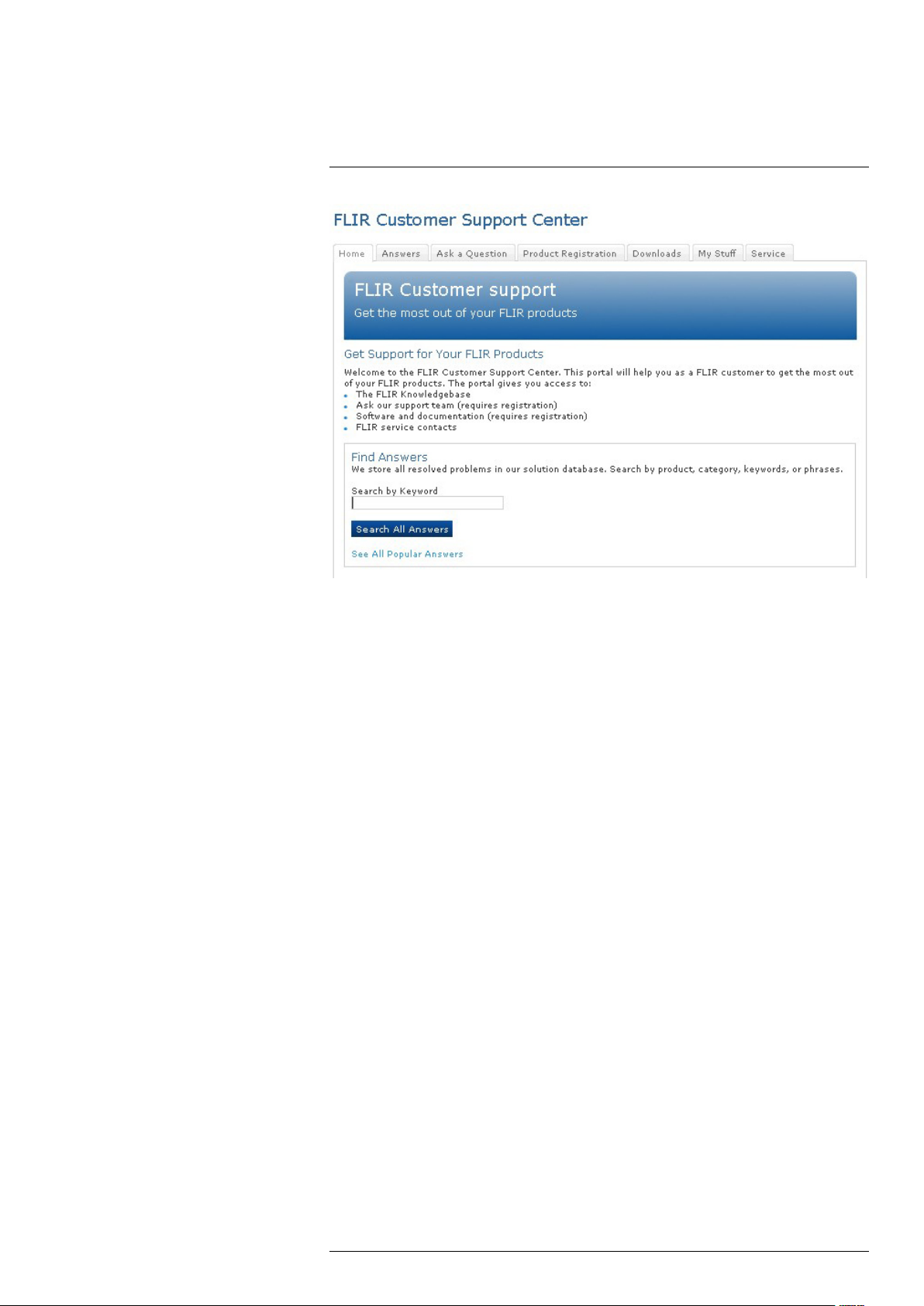
4.1 General
For customer help, visit:
http://support.flir.com
4.2 Submitting a question
To submit a question to the customer help team, you must be a registered user. It only
takes a few minutes to register online. If you only want to search the knowledgebase for
existing questions and answers, you do not need to be a registered user.
When you want to submit a question, make sure that you have the following information
to hand:
• The camera model
• The camera serial number
• The communication protocol, or method, between the camera and your device (for example, HDMI, Ethernet, USB, or FireWire)
• Device type (PC/Mac/iPhone/iPad/Android device, etc.)
• Version of any programs from FLIR Systems
• Full name, publication number, and revision number of the manual
4.3 Downloads
On the customer help site you can also download the following:
• Firmware updates for your infrared camera.
• Program updates for your PC/Mac software.
• Freeware and evaluation versions of PC/Mac software.
• User documentation for current, obsolete, and historical products.
• Mechanical drawings (in *.dxf and *.pdf format).
• Cad data models (in *.stp format).
• Application stories.
• Technical datasheets.
• Product catalogs.
#T559879; r.18035/18166; en-US
7
Page 20

5
Quick start guide
5.1 Procedure
Follow this procedure:
1. Put a battery into the battery compartment.
2. Charge the battery for 4 hours before starting the camera for the first time.
3. Insert a memory card into the card slot.
4. Push the On/off button
5. Aim the camera toward the object of interest.
6. Adjust the focus.
Note
It is very important to adjust the focus correctly. Incorrect focus adjustment affects how the image
modes work. It also affects the temperature measurement.
7. Push the Autofocus/save button fully down to save an image.
8. Go to http://support.flir.com/tools and download FLIR Tools.
9. Install FLIR Tools on your computer.
10. Start FLIR Tools.
11. Connect the camera to the computer using a USB cable.
12. Import the images into FLIR Tools.
13. Select one or more images.
14. Click Generate report.
15. Click Export to export the report as a PDF file.
16. Send the PDF report to your client.
to turn on the camera.
#T559879; r.18035/18166; en-US
8
Page 21

6
List of accessories and services
Part number Product name
T197650 2-bay battery charger, incl. power supply with mul-
1196398ACC
T197667 Battery package
T197771ACC Bluetooth Headset
T199802 Calibration including General maintenance T2xx-
ITC-FEE-0120 Certification DIN EN ISO 9712 TT Category 1
T198509 Cigarette lighter adapter kit, 12 VDC, 1.2 m/3.9 ft.
T197214
T197215
ITC-CER-6101 DIN EN ISO 9712 Certification course TT Cate-
ITC-CER-6109 DIN EN ISO 9712 Certification course TT Cate-
DSW-10000 FLIR IR Camera Player
T198586 FLIR Reporter Professional (license only)
T198578 FLIR ResearchIR 3 (license only)
T198574 FLIR ResearchIR 3 Max (license only)
T198697 FLIR ResearchIR Max + HSDR 4
T198696 FLIR ResearchIR Max 4
T198731 FLIR ResearchIR Standard 4
T198584 FLIR Tools
APP-10004 FLIR Tools (MacOS Application)
APP-10002 FLIR Tools Mobile (Android Application)
APP-10003
T198583 FLIR Tools+ (license only)
T198370ACC Hard transport case for FLIR T/B2xx-4xx
T197000
T197412 IR lens, 4 mm (90°) with case and mounting sup-
T197408 IR lens, 76 mm (6°) with case and mounting sup-
1196960
1196961
19250-100 IR Window 2 in
19251-100 IR Window 3 in.
19252-100 IR Window 4 in.
ITC-ADV-3021 ITC Advanced General Thermography Course -
ITC-ADV-3029 ITC Advanced General Thermography Course-
ITC-CON-1001 ITC conference fee
ITC-EXP-0521 ITC Getting Started with Thermography (evening
ti plugs
Battery
T4xx series
Close-up 2× (50 µm) incl. case
Close-up 4× (100 µm) incl. case
gory 1, excl. Certification, 1 pers.
gory 1, excl. Certification, group up to 10 pers.
FLIR Tools Mobile (iPad/iPhone Application)
High temp. option +1200°C/+2192°F for FLIR T/
B2xx to T/B4xx and A3xx, A3xxf, A3xxpt, A3xxsc
series
port for T/B2xx-4xx
port for T/B-200/400
IR lens, f = 10 mm, 45° incl. case
IR lens, f = 30 mm, 15° incl. case
attendance, 1 pers.
group of 10 pers.
or weekend) - attendance, 1 pers.
#T559879; r.18035/18166; en-US
9
Page 22

6
List of accessories and services
Part number Product name
ITC-EXP-0511 ITC Getting Started with Thermography - attend-
ance, 1 pers.
ITC-EXP-1021 ITC In-house training - additional attendance 1
pers. (per day)
ITC-EXP-1029 ITC In-house training - group up to 10 pers. (per
day)
ITC-CER-5105 ITC Level 1 Thermography Course - additional
student to on site class, 1 pers
ITC-CER-5101 ITC Level 1 Thermography Course - attendance,
1 pers.
ITC-CER-5109 ITC Level 1 Thermography Course – group of 10
pers.
ITC-CER-5205 ITC Level 2 Thermography Course - additional
student to on site class, 1 pers
ITC-CER-5201 ITC Level 2 Thermography Course - attendance,
1 pers.
ITC-CER-5209 ITC Level 2 Thermography Course – group of 10
pers.
ITC-PRA-2011 ITC Practical Course - Solar panel inspection - at-
tendance, 1 pers (2 days)
ITC-PRA-2019 ITC Practical Course - Solar panel inspection -
group up to 10 pers (2 days)
ITC-EXP-2041 ITC Short course electrical thermography - attend-
ance 1 pers. (2 days)
ITC-EXP-2049 ITC Short course electrical thermography - inclu-
sive 10 pers. (2 days)
ITC-EXP-1019 ITC Short course Introduction to thermography -
inclusive 10 pers. (1 day)
ITC-EXP-1011 ITC Short course Introduction to thermography
-attendance 1 pers. (1 day)
ITC-SOW-0001 ITC Software course - attendance 1 pers. (per
day)
ITC-SOW-0009 ITC Software course - group up to 10 pers. (per
day)
ITC-EXP-1001 ITC Training 1 day - attendance 1 pers.
ITC-EXP-1009 ITC Training 1 day - group up to 10 pers.
ITC-EXP-2001 ITC Training 2 days - attendance 1 pers.
ITC-EXP-2009 ITC Training 2 days - group up to 10 pers.
ITC-EXP-3001 ITC Training 3 days - attendance 1 pers.
ITC-EXP-3009 ITC Training 3 days - group up to 10 pers.
ITC-SOW-1001 ITC Training FLIR Software - attendance 1 pers.
(1 day)
ITC-SOW-2001 ITC Training FLIR Software - attendance 1 pers.
(2 days)
ITC-TFT-0100 ITC travel time for instructor
T911230ACC Memory card SDHC 4 GB
T198499 Neck strap
T199815 One year extended warranty for T2xx-4xx series
1124545 Pouch
T198495 Pouch for FLIR T6xx and T4xx series
T910814 Power supply, incl. multi plugs
#T559879; r.18035/18166; en-US
10
Page 23

6
List of accessories and services
Part number Product name
ITC-FEE-0130 Repeat Certification DIN EN ISO 9712 IT Cate-
19250-200
19251-200
19252-200
T198493
T911093 Tool belt
ITC-TOL-1003 Travel and lodging expenses instructor (Center
ITC-TOL-1001 Travel and lodging expenses instructor (Europe,
ITC-TOL-1005 Travel and lodging expenses instructor (other)
ITC-TOL-1002 Travel and lodging expenses instructor (Russia/
ITC-TOL-1004 Travel and lodging expenses instructor (various)
1910423
1910582ACC Video cable
gory 1
SS IR Window 2 in.
SS IR Window 3 in.
SS IR Window 4 in.
Sun shield
and South Africa)
Balcans, Turkey, Cyprus)
GUS, Middle East, North Africa)
USB cable Std A <-> Mini-B
Note
FLIR Systems reserves the right to discontinue models, parts or accessories, and other items, or to
change specifications at any time without prior notice.
#T559879; r.18035/18166; en-US
11
Page 24
7
A note about ergonomics
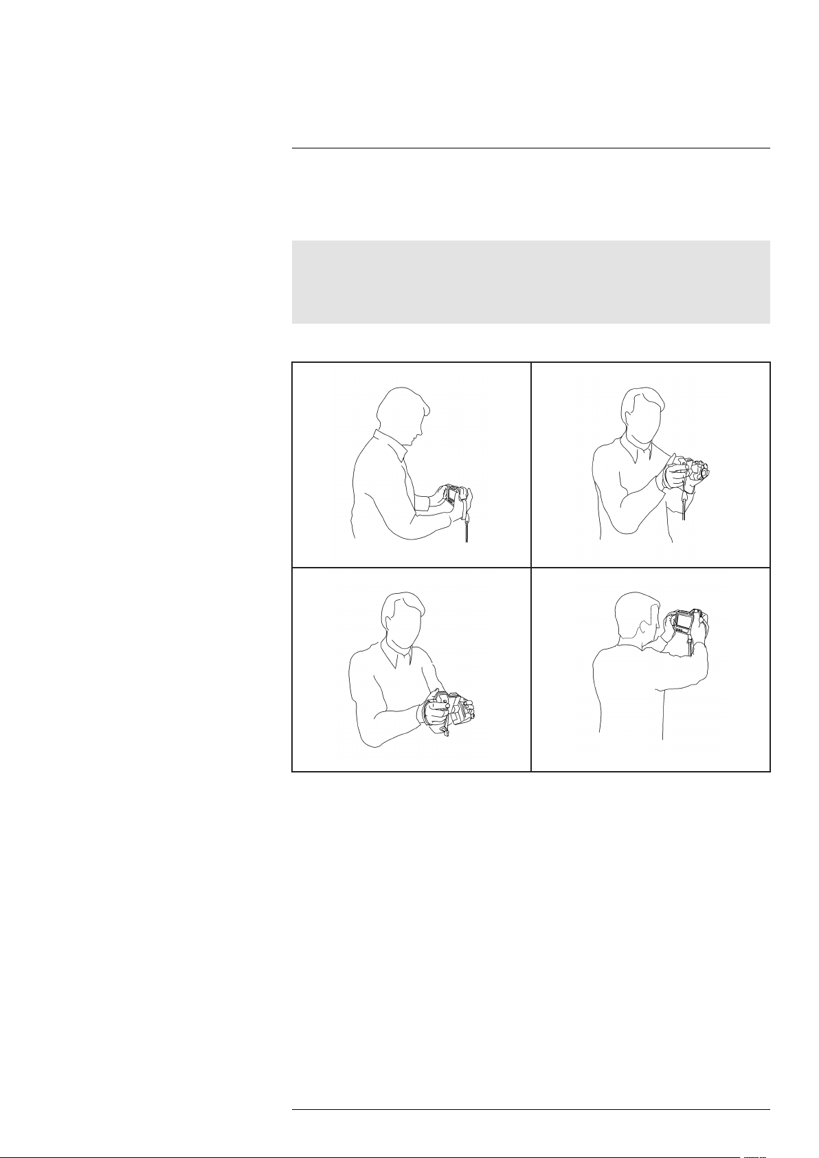
7.1 General
To prevent strain-related injuries, it is important that you hold the camera ergonomically
correct. This section gives advice and examples on how to hold the camera.
Note
Please note the following:
• Always tilt the touch-screen LCD to suit your work position.
• When you hold the camera, make sure that you support the optics housing with your left hand too.
This decreases the strain on your right hand.
7.2 Figure
#T559879; r.18035/18166; en-US
12
Page 25
8
Camera parts
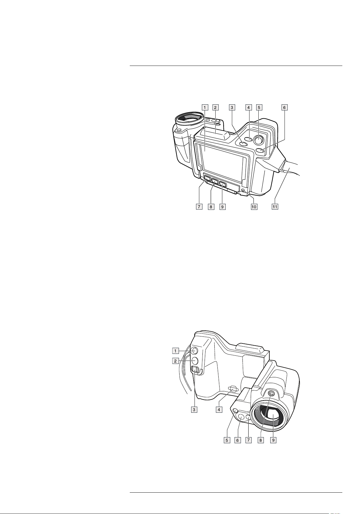
8.1 View from the rear
8.1.1 Figure
8.1.2 Explanation
1. Touch-screen LCD.
2. Antenna for wireless communication.
3. Digital zoom button.
4. Programmable button.
5. Joystick with push-button functionality.
6. Back button.
7. Camera lamp button.
8. Button to switch between automatic and manual image adjustment mode.
9. Image archive button.
10. On/off button.
11. Hand strap.
8.2 View from the front
8.2.1 Figure
8.2.2 Explanation
1. Laser pointer button. Push to activate the laser pointer.
2. Autofocus/save button.
#T559879; r.18035/18166; en-US
13
Page 26
8
Camera parts
3. Focus button. Move left/right to focus the camera.
4. Attachment point for the neck strap.
5. Camera lamp.
6. Digital camera.
7. Release button for additional infrared lenses.
8. Laser pointer.
Note
The laser pointer may not be enabled in all markets.
9. Infrared lens.
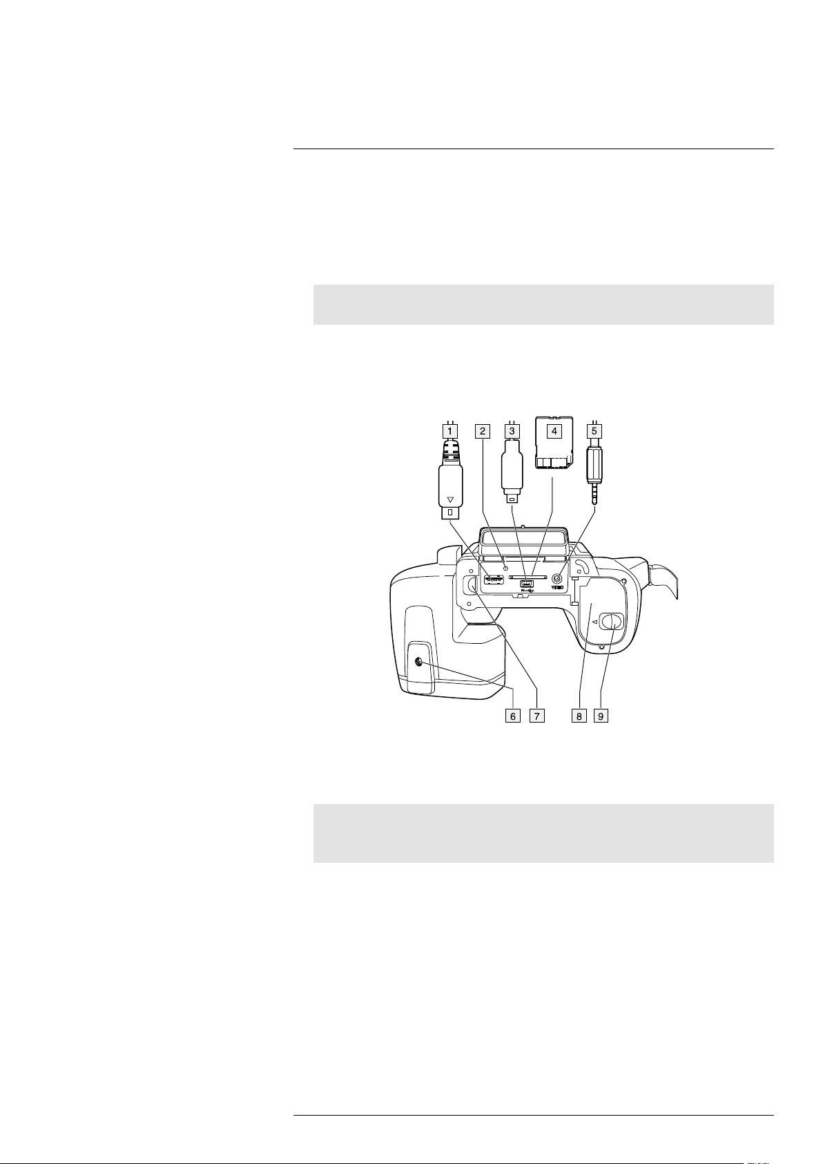
8.3 View from the bottom
8.3.1 Figure
8.3.2 Explanation
1. USB-A cable (to connect an external USB device to the camera).
2. Indicator showing that the memory card is busy.
Note
• Do not eject the memory card when this LED is flashing.
• Do not connect the camera to a computer when this LED is flashing.
3. USB Mini-B cable (to connect the camera to a computer).
4. Memory card.
5. Video cable (composite video).
6. Tripod mount 1/4″-20.
7. Latch for the cover to the connector bay.
8. Battery compartment cover.
9. Latch for the battery compartment cover.
#T559879; r.18035/18166; en-US
14
Page 27
8
Camera parts
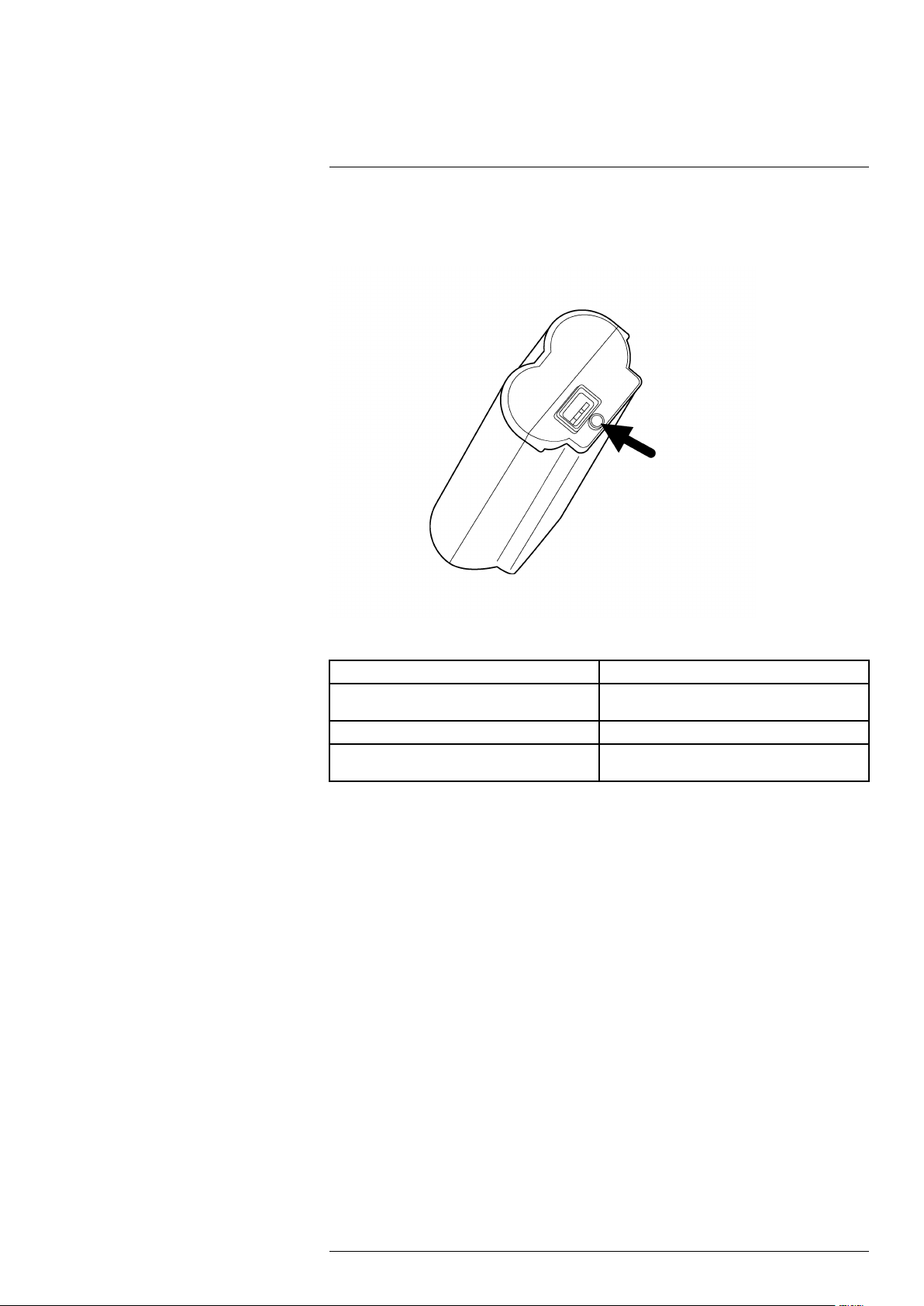
8.4 Battery condition indicator
8.4.1 Figure
8.4.2 Explanation
Type of signal Explanation
The green light flashes. The power supply or the stand-alone battery
The green light is continuous. The battery is fully charged.
The green light is off. The camera is using the battery (instead of the
charger is charging the battery.
power supply).
#T559879; r.18035/18166; en-US
15
Page 28
8
Camera parts
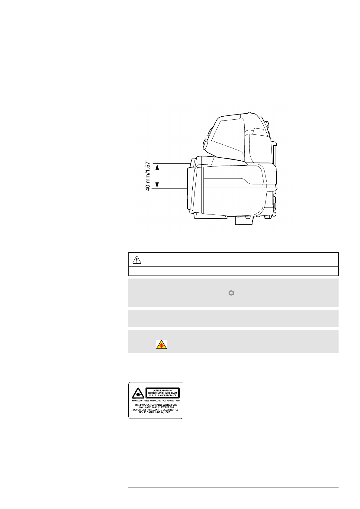
8.5 Laser pointer
8.5.1 Figure
Figure 8.1 This figure shows the difference in position between the laser pointer and the optical center of
the infrared lens.
WARNING
Do not look directly into the laser beam. The laser beam can cause eye irritation.
Note
The laser pointer is enabled by a setting. Select
Lamp & laser > Enable lamp & laser.
Note
The laser pointer may not be enabled in all markets.
Note
The symbol
is displayed on the screen when the laser pointer is on.
(Settings) > Device settings > Set up camera >
8.5.2 Laser warning label
A laser warning label with the following information is attached to the camera:
8.5.3 Laser rules and regulations
Wavelength: 635 nm. Maximum output power: 1 mW.
This product complies with 21 CFR 1040.10 and 1040.11 except for deviations pursuant
to Laser Notice No. 50, dated June 24, 2007.
#T559879; r.18035/18166; en-US
16
Page 29
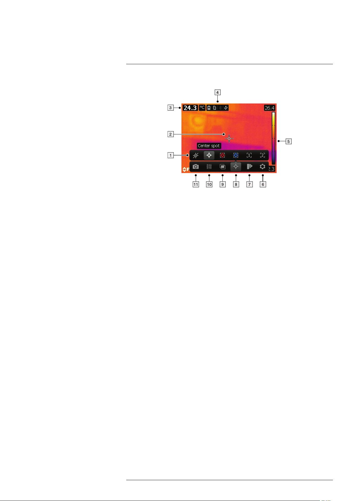
9
Screen elements
9.1 Figure
9.2 Explanation
1. Measurement toolbar.
2. Measurement tool (e.g., spotmeter).
3. Result table.
4. Status icons.
5. Temperature scale.
6. Settings toolbar button.
7. Color toolbar button.
8. Measurement toolbar button.
9. Image mode toolbar button.
10. Measurement parameters toolbar button.
11. Recording mode toolbar button.
#T559879; r.18035/18166; en-US
17
Page 30
10
Navigating the menu system
10.1 Figure
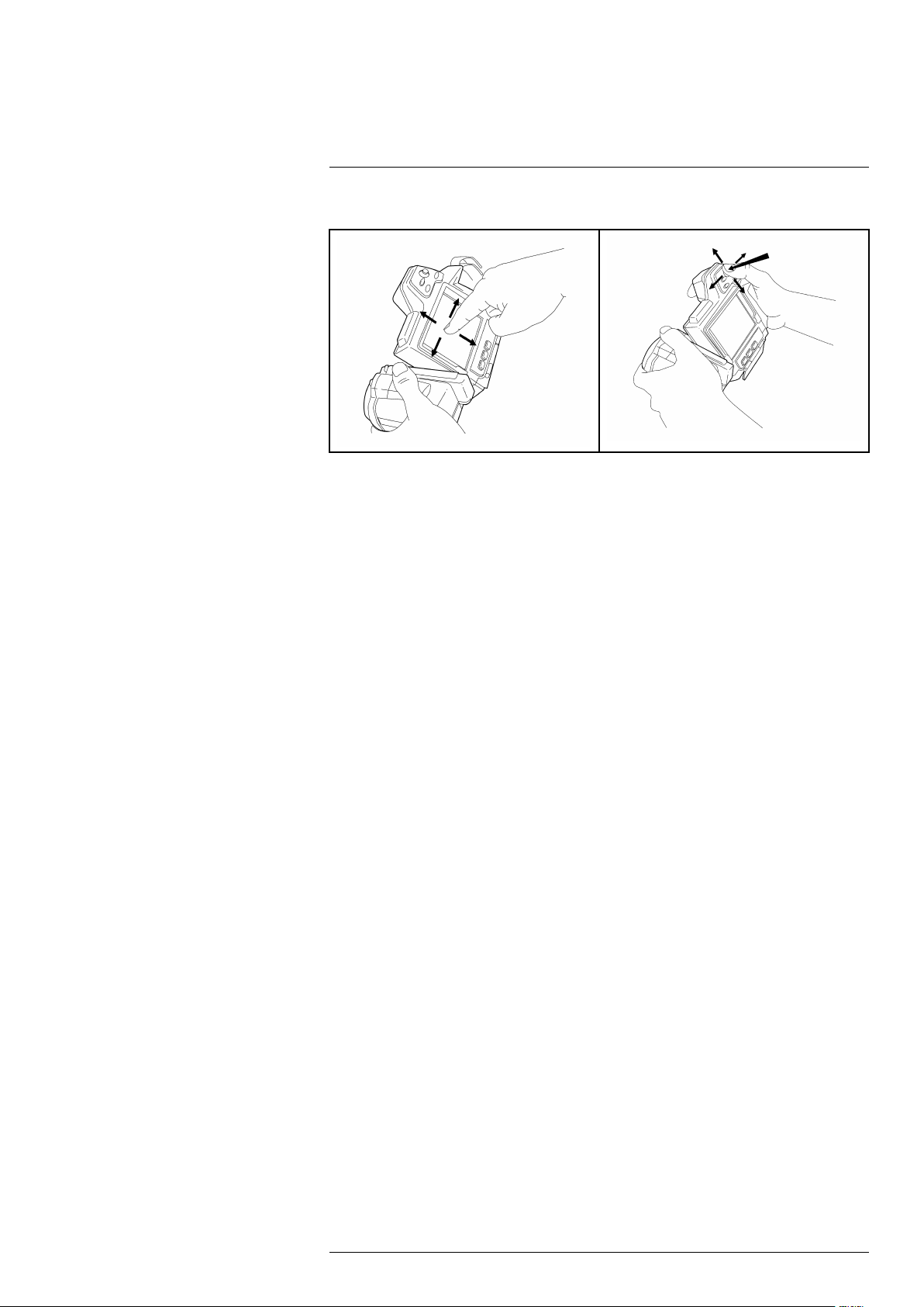
10.2 Explanation
The figure above shows the two ways to navigate the menu system in the camera:
• Using the index finger or a stylus pen specially designed for capacitive touch usage to
navigate the menu system (left).
• Using the joystick to navigate the menu system (right).
You can also use a combination of the two.
In this manual it is assumed that the joystick is used, but most tasks can also be carried
out using the index finger or a stylus pen.
#T559879; r.18035/18166; en-US
18
Page 31

11
Pairing Bluetooth devices
11.1 General
Before you can use a Bluetooth device with the camera, you need to pair the devices.
11.2 Procedure
Follow this procedure:
1. Push the joystick to display the menu system.
2. Use the joystick to go to
3. Push the joystick to display the Settings menu.
4. Select Device settings and push the joystick.
5. Select Bluetooth including METERLiNK and push the joystick.
6. If the Bluetooth check box is unchecked, push the joystick to activate Bluetooth.
Note
You also need to activate Bluetooth connectivity on the external device.
7. Select Scan for Bluetooth devices and push the joystick.
8. Wait until a list of available devices is displayed. This will take about 15 seconds.
9. When a Bluetooth device is found, select the device to add it and begin the pairing
procedure. The device is then ready to be used.
Note
• Only METERLiNK devices and Bluetooth-enabled headsets will appear in the list of available
devices.
• You can add several devices.
• You can remove a device by selecting the device and then selecting Unpair device.
• After adding a METERLiNK device, such as the FLIR MR77 or FLIR DM93, the result from the meter will be visible in the result table.
• After adding a Bluetooth-enabled headset, it is ready to be used for adding voice annotations.
(Settings).
#T559879; r.18035/18166; en-US
19
Page 32

12
Configuring Wi-Fi
12.1 General
Depending on your camera configuration, you can connect the camera to a wireless local
area network (WLAN) using Wi-Fi, or let the camera provide Wi-Fi access to another
device.
You can connect the camera in two different ways:
• Most common use: Setting up a peer-to-peer connection (also called an ad hoc or
P2P connection). This method is primarily used with other devices, e.g., an iPhone or
iPad.
• Less common use: Connecting the camera to a WLAN.
12.2 Setting up a peer-to-peer connection (most common use)
Follow this procedure:
1. Push the joystick to display the menu system.
2. Use the joystick to go to
3. Push the joystick to display the Settings menu.
4. Select Device settings and push the joystick.
5. Select Wi-Fi and push the joystick.
6. Select Share IRCAMxxxx and push the joystick.
7. (Optional step.) To display and change the parameters, select Settings and push the
joystick.
• To change the channel (the channel that the camera is broadcasting on), select
Channel and push the joystick.
• To activate WEP (encryption algorithm), select WEP and push the joystick. This
will check the WEP check box.
• To change the WEP password, select Password and push the joystick.
Note
These parameters are set for your camera’s network. They will be used by the external device to
connect that device to the network.
12.3 Connecting the camera to a wireless local area network (less common use)
Follow this procedure:
1. Push the joystick to display the menu system.
2. Use the joystick to go to
3. Push the joystick to display the Settings menu.
4. Select Device settings and push the joystick.
5. Select Wi-Fi and push the joystick.
6. Select Connect to network and push the joystick.
7. To display a list of the available networks, select Networks and push the joystick.
8. Select one of the available networks.
Password-protected networks are indicated with a padlock icon, and for these you
will need to enter a password.
(Settings).
(Settings).
Note
Some networks do not broadcast their existence. To connect to such a network, select Settings from
the Networks list and push the joystick. Then select Add network... and set all parameters manually according to that network.
#T559879; r.18035/18166; en-US
20
Page 33

13
Handling the camera
13.1 Charging the battery
Note
You must charge the battery for 4 hours before you start using the camera for the first time.
13.1.1 General
You must charge the battery when a low battery voltage warning is displayed on the
screen.
Follow one of these procedures to charge the battery:
• Use the combined power supply and battery charger to charge the battery when it is
inside the camera.
• Use the combined power supply and battery charger to charge the battery when it is
outside the camera.
• Use the stand-alone battery charger to charge the battery.
13.1.2 Using the combined power supply and battery charger to charge the
battery when it is inside the camera
Note
For brevity, the ‘combined power supply and battery charger’ is called the ‘power supply’ below.
13.1.2.1 Procedure
Follow this procedure:
1. Open the battery compartment cover.
2. Connect the power supply cable plug to the connector on the battery.
3. Connect the power supply mains-electricity plug to a mains socket.
4. Disconnect the power supply cable plug when the green light of the battery condition
indicator is continuous.
See also:
For information about the battery condition indicator, see 8.4 Battery condition indicator,
page 15.
13.1.3 Using the combined power supply and battery charger to charge the
battery when it is outside the camera
Note
For brevity, the ‘combined power supply and battery charger’ is called the ‘power supply’ below.
13.1.3.1 Procedure
Follow this procedure:
1. Put the battery on a flat surface.
2. Connect the power supply cable plug to the connector on the battery.
3. Connect the power supply mains-electricity plug to a mains socket.
4. Disconnect the power supply cable plug when the green light of the battery condition
indicator is continuous.
See also:
For information about the battery condition indicator, see 8.4 Battery condition indicator,
page 15.
#T559879; r.18035/18166; en-US
21
Page 34

Handling the camera13
13.1.4 Using the stand-alone battery charger to charge the battery
13.1.4.1 Procedure
Follow this procedure:
1. Put the battery in the stand-alone battery charger.
2. Connect the power supply cable plug to the connector on the stand-alone battery
charger.
3. Connect the power supply mains-electricity plug to a mains socket.
4. Disconnect the power supply cable plug when the green light of the battery condition
indicator is continuous.
See also:
For information about the battery condition indicator, see 8.4 Battery condition indicator,
page 15.
13.2 Inserting the battery
Note
Use a clean, dry cloth to remove any water or moisture on the battery before you insert it.
13.2.1 Procedure
Follow this procedure:
1. Push the release button on the battery compartment cover to unlock it.
2. Open the cover to the battery compartment.
3. Push the battery into the battery compartment until the battery-locking mechanism
engages.
#T559879; r.18035/18166; en-US
22
Page 35

Handling the camera13
4. Close the cover to the battery compartment.
13.3 Removing the battery
13.3.1 Procedure
Follow this procedure:
1. Push the release button on the battery compartment cover to unlock it.
2. Open the cover to the battery compartment.
3. Push the red release button in the direction of the arrow to unlock the battery.
4. Pull out the battery from the battery compartment.
#T559879; r.18035/18166; en-US
23
Page 36

Handling the camera13
13.4 Turning on and turning off the camera
• Push the
• Push and hold the
button to turn on the camera.
button for less than 5 seconds to put the camera in standby
mode. The camera then automatically turns off after 6 hours.
• Push and hold the
button for more than 10 seconds to turn off the camera.
13.5 Adjusting the angle of lens
13.5.1 Figure
13.5.2 Procedure
To adjust the angle, tilt the lens up or down.
13.6 Adjusting the infrared camera focus
13.6.1 Procedure
To adjust the infrared camera focus, do one of the following:
• Push the focus button left for far focus.
• Push the focus button right for near focus.
• Push the Autofocus/save button halfway down to autofocus the camera.
Note
It is important that you hold the camera steady while autofocusing.
13.7 Mounting an additional lens
Note
Do not touch the lens surface when you mount an infrared lens. If this happens, clean the lens according to the instructions in 28.2 Infrared lens, page 114.
#T559879; r.18035/18166; en-US
24
Page 37

Handling the camera13
13.7.1 Procedure
Follow this procedure:
1. Push the lens release button to unlock the lens cap.
2. Rotate the lens cap 30° counter-clockwise (looking at the front of the lens).
3. Carefully pull out the lens cap from the bayonet ring.
4. Correctly position the lens in front of the bayonet ring.
#T559879; r.18035/18166; en-US
25
Page 38

Handling the camera13
5. Carefully push the lens into position.
6. Rotate the lens 30° clockwise (looking at the front of the lens).
13.8 Removing an additional infrared lens
Note
Do not touch the lens surface when you mount an infrared lens. If this happens, clean the lens according to the instructions in 28.2 Infrared lens, page 114.
When you have removed the lens, put the lens caps on the lens immediately, to protect it from dust and
fingerprints.
13.8.1 Procedure
Follow this procedure:
1. Push the lens release button to unlock the lens.
#T559879; r.18035/18166; en-US
26
Page 39

Handling the camera13
2. Rotate the lens counter-clockwise 30° (looking at the front of the lens).
3. Carefully pull out the lens from the bayonet ring.
4. Correctly position the lens cap in front of the bayonet ring.
5. Carefully push the lens cap into position.
#T559879; r.18035/18166; en-US
27
Page 40

Handling the camera13
6. Rotate the lens cap 30° clockwise (looking at the front of the lens).
13.9 Attaching the sunshield
13.9.1 Procedure
Follow this procedure:
1. Align the two front tabs of the sunshield with the corresponding two notches at the
top of the screen.
2. Push the front part of the sunshield into position. Make sure that the two tabs mate
with the corresponding notches.
3. Carefully hold together the two rear wings of the sunshield.
#T559879; r.18035/18166; en-US
28
Page 41

Handling the camera13
4. Push the rear part of the sunshield toward the screen, and then release your grip.
Make sure that the two tabs mate with the corresponding notches.
13.10 Using the laser pointer
Note
The laser pointer is enabled by a setting. Select
Lamp & laser > Enable lamp & laser.
(Settings) > Device settings > Set up camera >
13.10.1 Figure
13.10.2 Procedure
Follow this procedure:
1. To turn on the laser pointer, push and hold the laser pointer button.
2. To turn off the laser pointer, release the laser pointer button.
Note
The laser pointer may not be enabled in all markets.
Note
The symbol
is displayed on the screen when the laser pointer is on.
13.11 Calibrating the compass
13.11.1 Procedure
Follow this procedure:
1. Push the joystick to display the menu system.
#T559879; r.18035/18166; en-US
29
Page 42

Handling the camera13
2. Use the joystick to go to (Settings).
3. Push the joystick to display the Settings menu.
4. Select Device settings and push the joystick.
5. Select Compass and push the joystick.
6. Select Compass. If the Compass check box is unchecked, push the joystick to enable the compass.
7. Select Calibrate compass and push the joystick. Follow the on-screen instructions.
Note
You must rotate the camera slowly.
13.12 Calibrating the touchscreen LCD
13.12.1 Figure
13.12.2 Procedure
Follow this procedure:
1. Push the joystick to display the menu system.
2. Use the joystick to go to
(Settings).
3. Push the joystick to display the Settings menu.
4. Select Device settings and push the joystick.
5. Select Set up camera and push the joystick.
6. Select Calibrate touchscreen and push the joystick.
7. Calibrate the touchscreen by tapping the five crosshairs that appear on the screen
using a stylus pen specially designed for capacitive touch usage.
8. When completed, push the joystick.
13.13 Using the camera lamp as a flash
13.13.1 General
The camera lamp can be used as a flash for the digital camera. When the flash function
is activated, the camera lamp will flash when an image is saved by pushing the Autofocus/Save button fully down.
13.13.2 Procedure
Follow this procedure:
1. Push the joystick to display the menu system.
#T559879; r.18035/18166; en-US
30
Page 43

Handling the camera13
2. Use the joystick to go to
(Settings).
3. Push the joystick to display the Settings menu.
4. Select Device settings and push the joystick.
5. Select Set up camera and push the joystick.
6. Select Lamp & laser and push the joystick.
7. Select Enable lamp & laser. If the check box is unchecked, push the joystick to enable the camera lamp.
8. Select Use lamp as flash. If the check box is unchecked, push the joystick to activate
the flash function.
#T559879; r.18035/18166; en-US
31
Page 44

14
Working with images
14.1 Saving an image
14.1.1 General
You can save images to a memory card.
The camera saves an image file including all thermal and visual information. This means
that you can open an image file at a later stage and, for example, select another image
mode, apply color alarms, and add measurement tools.
The image jpg file is fully radiometric and saved lossless, which enables full post-processing in FLIR Tools. There is also a regular jpg part (lossy) for convenient viewing in
non-FLIR Systems software (Explorer).
14.1.2 About UltraMax
UltraMax is an image enhancement feature that will increase the image resolution and
lower the noise, making small objects easier to see and measure. An UltraMax image is
twice as wide and high as an ordinary image.
When an UltraMax image is captured by the camera, several ordinary images are saved
in the same file. Capturing all the images can take up to one second. To fully utilize UltraMax, the images need to be slightly different, which can be accomplished by a slight
movement of the camera. You should hold the camera firmly in your hands (do not put it
on a tripod), which will make these images vary just a little during the capture. Correct focus, a high-contrast scene, and a non-moving target are other conditions that help to
achieve a good-quality UltraMax image.
At the moment, only FLIR Tools has the ability to process UltraMax images. Other FLIR
software will treat the image as a regular image.
14.1.3 Image capacity
The capacity of a 4 GB memory card is theoretically 13 000 images (with no annotations).
Note
Although a memory card may have a higher capacity than 5000 images, saving more than that number
of images severely slows down file management on the memory card.
14.1.4 Naming convention
The naming convention for image files is FLIRxxxx.jpg, where xxxx is a unique counter.
14.1.5 Procedure
Follow this procedure:
1. To save an image, push the Autofocus/Save button fully down.
Note
• Depending on the settings in
• A preview image is displayed before the image is saved.
• An annotation tool or the annotation menu is displayed when the image has been saved.
• To configure the camera UltraMax, select
UltraMax.
• The camera can be configured to also save the visual image as a separate file. Select
tings) > Save options > Photo as separate JPEG = On.
(Settings) > Save options, the following may happen:
(Settings) > Save options > Image resolution =
(Set-
#T559879; r.18035/18166; en-US
32
Page 45

Working with images14
14.2 Previewing an image
14.2.1 General
You can preview an image before you save it. This enables you to see if the image contains the information you want before you save it. You can also adjust and edit the image.
Note
The camera must be configured to display a preview image before saving. Select
Save options > Preview image before saving = On.
(Settings) >
14.2.2 Procedure
Follow this procedure:
1. To preview an image, push the Autofocus/Save button fully down. This displays the
preview.
2. Manual image adjust mode is now active, and the status icon
is displayed. For
image adjustment instructions, see 14.5 Adjusting an infrared image, page 34.
3. To edit the image, push the joystick. This displays a context menu. For editing instructions, see 14.4 Editing a saved image, page 33.
4. Do one of the following:
• To save the image, push the Autofocus/Save button fully down.
• To exit preview mode without saving, push the Back button
.
14.3 Opening a saved image
14.3.1 General
When you save an image, the image file is stored on the memory card. To display the image again, open it from the image archive.
14.3.2 Procedure
Follow this procedure:
1. Push the Image archive button
.
2. Move the joystick up/down or left/right to select the image you want to view.
3. Push the joystick. This will display the image at full size.
4.
Do one or more of the following:
• To switch between an infrared image and a visual image, move the joystick up/
down.
• To view the previous/next image, move the joystick left/right.
• To edit the image, add annotations, display information, or delete the image, push
the joystick. This displays a context menu.
• To return to the image archive overview, push the Back button
.
14.4 Editing a saved image
14.4.1 General
You can edit a saved image. You can also edit an image in preview mode.
14.4.2 Procedure
Follow this procedure:
1. Open the image in the image archive.
#T559879; r.18035/18166; en-US
33
Page 46

Working with images14
2. Push the joystick and select
3. Manual image adjust mode is now active, and the status icon
(Edit) from the menu.
is displayed. For
image adjustment instructions, see 14.5 Adjusting an infrared image, page 34.
4. Push the joystick. This displays a context menu.
• Select
• Select
• Select
• Select
• Select
• Select
(Cancel) to exit edit mode.
(Measurement parameters) to change the global parameters.
(Image mode) to change the image mode.
(Measurement) to add a measurement tool.
(Color) to change the color palette or set a color alarm.
(Save) to save and exit edit mode.
14.5 Adjusting an infrared image
14.5.1 General
An infrared image can be adjusted automatically or manually. When manual image adjust
mode is active, the status icon
• In live mode, push the button
is displayed.
to switch between automatic and manual image adjust
modes. You can also switch between the modes by touching the temperature scale
on the screen.
• In preview/edit mode, manual image adjust mode is active.
14.5.2 Example 1
This figure shows two infrared images of cable connection points. In the left image, a correct analysis of the circled cable is difficult if you only auto-adjust the image. You can analyze this cable in more detail if you:
• Change the temperature scale maximum limit.
• Change the temperature scale minimum limit.
• Change the temperature scale maximum and minimum limits.
In the left image, the image is auto-adjusted. In the right image, the maximum and mini-
mum temperature levels have been changed to temperature levels near the object. On
the temperature scale to the right of each image you can see how the temperature levels
were changed.
14.5.3 Example 2
This figure shows two infrared images of an isolator in a power line.
#T559879; r.18035/18166; en-US
34
Page 47

Working with images14
In the left image, the cold sky and the power line structure are recorded at a minimum
temperature of –26.0°C (–14.8°F). In the right image, the maximum and minimum temperature levels have been changed to temperature levels near the isolator. This makes it
easier to analyze the temperature variations in the isolator.
14.5.4 Procedure
Follow this procedure:
1. In live mode, push the button
to enter manual image adjust mode.
2. To change the temperature scale minimum and maximum limits simultaneously,
move the joystick up/down.
3. To change the temperature scale minimum or maximum limit, do the following:
• Move the joystick left/right to select (highlight) the maximum or minimum
temperature.
• Move the joystick up/down to change the value of the highlighted temperature.
4. (Optional step). In preview/edit mode, push the button
to perform a one-shot auto-
adjust sequence.
14.6 Performing a non-uniformity correction (NUC)
14.6.1 What is a non-uniformity correction?
A non-uniformity correction is an image correction carried out by the camera software to
compensate for different sensitivities of detector elements and other optical and geometrical disturbances
1
.
14.6.2 When to perform a non-uniformity correction?
The non-uniformity correction process should be carried out whenever the output image
becomes spatially noisy. The output can become spatially noisy when the ambient temperature changes (such as from day to night operation, and vice versa).
14.6.3 Procedure
To perform a non-uniformity correction, push and hold the Image archive button
for
more than 2 seconds.
14.7 Changing the temperature range
14.7.1 General
You must change the temperature range according to the expected temperature of the
object you are inspecting.
1. Definition from the impending international adoption of DIN 54190-3 (Non-destructive testing – Thermographic
testing – Part 3: Terms and definitions).
#T559879; r.18035/18166; en-US
35
Page 48

Working with images14
14.7.2 Procedure
Follow this procedure:
1. Push the joystick to display the menu system.
2. Use the joystick to go to
(Settings).
3. Push the joystick to display the Settings menu.
4. Select Device settings and push the joystick.
5. Select Set up camera and push the joystick.
6. Select Camera temperature range and push the joystick.
7. Select the appropriate temperature range and push the joystick.
Note
You can also assign the function Switch temperature range to the programmable button. Select
(Settings) > Programmable button > Switch temperature range.
14.8 Hiding overlay graphics (programmable button)
14.8.1 General
Overlay graphics provide information about an image, e.g., measurement functions and
parameters. You can choose to hide all overlay graphics.
14.8.2 Procedure
Follow this procedure:
1. Push the joystick to display the menu system.
2. Use the joystick to go to
(Settings).
3. Push the joystick to display the Settings menu.
4. Select Programmable button and push the joystick.
5. Select Hide graphics and push the joystick. You have now assigned this function to
the button
. This is a programmable button, and you can assign other functions to
it.
Note
Other functions that can be associated with the programmable button include the following:
• Hide graphics
• Calibrate
• Switch Thermal <> Digital camera
• Switch Thermal <> Thermal MSX
• Switch 1x zoom <> Max zoom
• Switch between two latest palettes
• Switch temperature range
14.9 Changing the color palette
14.9.1 General
You can change the color palette that the camera uses to display different temperatures.
A different palette can make it easier to analyze an image.
14.9.2 Procedure
Follow this procedure:
1. Push the joystick to display the menu system.
2. Use the joystick to go to
(Color).
3. Push the joystick to display a submenu.
#T559879; r.18035/18166; en-US
36
Page 49

Working with images14
4. Use the joystick to select a different palette.
5. Push the joystick.
14.10 Deleting an image
14.10.1 General
You can delete an image from the memory card.
14.10.2 Procedure
Follow this procedure:
1. Push the Image archive button
.
2. Move the joystick up/down or left/right to select the image you want to delete.
3. Push the joystick to display the image.
4. Push the joystick to display a menu.
5. On the menu, select
(Delete).
6. Push the joystick and confirm the choice.
Note
Note that both images in the image file (thermal and visual) will be deleted.
14.11 Deleting all images
14.11.1 General
You can delete all images from the memory card.
14.11.2 Procedure
Follow this procedure:
1. Push the joystick to display the menu system.
2. Use the joystick to go to
(Settings).
3. Push the joystick to display the Settings menu.
4. Select Reset options and push the joystick.
5. Select Delete all saved images... and confirm the choice.
14.12 Creating a PDF report in the camera
14.12.1 General
You can create a PDF report and save it to the memory card. You can then transfer the
PDF report to a computer, iPhone, or iPad using FLIR Tools, and send the report to a
customer.
14.12.2 Naming convention
The naming convention for report files is REPORTxxxx.jpg, where xxxx is a unique
counter.
14.12.3 Procedure
Follow this procedure:
1. Push the Image archive button
.
2. Move the joystick up/down or left/right to select an image.
3. Push the joystick to display the image.
4. Push the joystick to display a context menu.
#T559879; r.18035/18166; en-US
37
Page 50

Working with images14
5. Select
(Information & reports) and push the joystick. This displays information
about the image.
6. Select Create report and push the joystick.
The created report will be available in the archive.
#T559879; r.18035/18166; en-US
38
Page 51

15
Working with image modes
15.1 General
The camera captures both thermal and visual images at the same time. By your choice
of image mode, you select which type of image to display on the screen.
The camera supports the following image modes:
• Thermal MSX (Multi Spectral Dynamic Imaging): The camera displays infrared images
where the edges of the objects are enhanced with visual image details.
• Thermal: A full infrared image is displayed.
• Picture in picture: An infrared image frame is displayed on top of the visual image.
• Digital camera: The visual image captured by the digital camera is displayed.
Note
These image modes only work correctly for calibrated lenses. The lens that ships with the camera is
factory calibrated. To have a new lens calibrated, you must send in the camera and the lens to your local service department.
15.2 Image examples
This table explains the different types of image modes.
Image mode Image
Thermal
Thermal MSX
#T559879; r.18035/18166; en-US
39
Page 52

Working with image modes15
Image mode Image
Picture in picture
Digital camera
15.3 Selecting the image mode
Follow this procedure:
1. Push the joystick to display the menu system.
2. Use the joystick to go to
(Image mode).
3. Push the joystick to display a submenu.
4. Use the joystick to go to one of the image modes:
•
(Thermal MSX)
•
(Thermal)
•
(Picture in picture)
•
(Digital camera)
5. Push the joystick confirm.
6. If Picture in picture mode is selected, you can at this point move and resize the image
frame using the touch screen.
#T559879; r.18035/18166; en-US
40
Page 53

16
Working with measurement tools
16.1 General
To measure a temperature, you can use one or more measurement tools, e.g., a spotmeter or a box.
16.2 Adding/removing measurement tools
Follow this procedure:
1. Push the joystick to display the menu system.
2. Use the joystick to go to
3. Push the joystick to display a submenu.
• Select
• Select
• Select
• Select
• Select
• Select
4. Push the joystick. This will display the measurement tool or the group of preset tools
on the screen.
16.3 Working with user presets
16.3.1 General
A user preset is a measurement tool, or a group of measurement tools, with predefined
characteristics.
16.3.2 Procedure
Follow this procedure:
1. Push the joystick to display the menu system.
(No measurements) to remove all tools.
(Center spot) to add a center spot.
(Hot spot) to add a hot spot detection within a box area.
(Cold spot) to add a cold spot detection within a box area.
(User preset 1) to add user preset 1.
(User preset 2) to add user preset 2.
(Measurement).
2. Use the joystick to go to
3. Push the joystick to display the Settings menu.
4. Select Define user presets and push the joystick.
5. Select Define preset 1 or Define preset 2 and push the joystick. This displays a context menu.
6. Select
7. Push the joystick. This displays a submenu.
• Select
• Select
• Select
• Select
• Select
8. Push the joystick. This displays the measurement tool on the screen.
#T559879; r.18035/18166; en-US
(Add measurement).
(Add spot) to add a spot.
(Add box) to add a box.
(Add circle) to add a circle.
(Add line) to add a line.
(Add delta) to set up a differential calculation.
(Settings).
41
Page 54

Working with measurement tools16
9. Push the joystick. This displays a context menu, where you can select one or more of
the following actions (depending on the type of tool):
• Remove the tool.
• Resize, move, center, rotate the tool.
• Display maximum, minimum, average values.
• Set alarms.
• Set local parameters.
• When completed, select
10. When all measurement tools have been added, select
(Done).
(Save as preset).
16.4 Resizing or moving a measurement tool
16.4.1 General
You can resize and move a measurement tool.
16.4.2 Procedure
Note
• This procedure assumes that you have previously laid out a measurement tool or user preset on the
screen.
• You can also move and resize the measurement tool by touching the screen.
Follow this procedure:
1. To select the measurement tool, touch the tool on the screen. The tool is now displayed with one or more handles.
Spot measurement tool:
Area measurement tool:
2. Push the joystick. This displays a context menu.
• Select
• Select
(Resize) to change the size of the tool.
(Move) to move the tool.
3. Move the joystick up/down and left/right to resize or move the tool.
4. When completed, push the joystick and select
(Done).
16.5 Changing object parameters
16.5.1 General
For accurate measurements, you must set the object parameters.
16.5.2 Types of parameters
The camera can use these object parameters:
• External IR window compensation, i.e., the temperature of any protective windows,
etc., that are set up between the camera and the object of interest. If no protective
window or protective shield is used, this value is irrelevant and should be left inactive.
• Object distance, i.e., the distance between the camera and the object of interest.
• Atmospheric temperature, i.e., the temperature of the air between the camera and the
object of interest.
#T559879; r.18035/18166; en-US
42
Page 55

Working with measurement tools16
• Relative humidity, i.e., the relative humidity of the air between the camera and the ob-
ject of interest.
• Reflected temperature, which is used when compensating for the radiation from the
surroundings reflected by the object into the camera. This property of the object is
called reflectivity.
• Emissivity, i.e., how much radiation an object emits, compared with the radiation of a
theoretical reference object at the same temperature (called a “blackbody”). The opposite of emissivity is reflectivity. The emissivity determines how much of the radiation
originates from the object as opposed to being reflected by it.
Note
There is an Emissivity mode setting, which you can use to enter the emissivity by material instead
of by value. Select
from materials table.
(Settings) > Device settings > Set up camera > Emissivity mode > Select
16.5.3 Recommended values
If you are unsure about the values, the following are recommended:
Object distance 1.0 m (3.3′)
Atmospheric temperature
Relative humidity 50%
Reflected temperature +20°C (+69°F)
Emissivity 0.95
+20°C (+69°F)
16.5.4 Procedure
You can set the object parameters globally. You can also change the Emissivity, Re-
flected temperature, and Object distance parameters locally for a measurement tool.
Note
Of the object parameters, Emissivity and Reflected temperature are the two most important to set correctly in the camera.
16.5.4.1 Setting global parameters
Follow this procedure:
1. Push the joystick to display the menu system.
2. Use the joystick to go to
(Measurement parameters).
3. Push the joystick to display a submenu. Use the joystick to select one or more of the
global object parameters:
•
(External IR window compensation)
•
(Object distance)
•
(Atmospheric temperature)
•
(Relative humidity)
(Reflected temperature)
•
•
(Emissivity)
4. Push the joystick to display a dialog box.
5. Use the joystick to change the parameter.
6. Push the joystick. This closes the dialog box.
#T559879; r.18035/18166; en-US
43
Page 56

Working with measurement tools16
16.5.4.2 Changing local parameters
You can change the local parameters for a measurement tool.
Follow this procedure:
1. To select the measurement tool, touch the tool on the screen. The tool is now displayed with one or more handles.
2. Push the joystick. This displays a context menu.
3. Use the joystick to go to
4. Push the joystick.
5. Push the joystick to activate the use of local parameters.
(Use local parameters).
(icon with grey indicator) is displayed.
(icon with blue indi-
cator) is displayed together with a submenu.
6. Select an object parameter.
7. Push the joystick to display a dialog box.
8. Use the joystick to change the parameter.
9. Push the joystick. This closes the dialog box.
10. When completed, push the joystick and select
(Done).
16.5.5 Related topics
For in-depth information about parameters, and how to correctly set the emissivity and
reflected apparent temperature, see 32 Thermographic measurement techniques, page
125.
16.6 Displaying values in the result table and displaying a graph
16.6.1 General
For the box, circle, and line tools, you can set the camera to display the maximum, minimum, and average values in the result table.
For the line tool, you can also display a graph.
16.6.2 Procedure
Follow this procedure:
1. To select the measurement tool, touch the tool on the screen. The tool is now displayed with one or more handles.
2. Push the joystick. This displays a context menu.
3. Use the joystick to go to (depending on the tool)
, , or (Max/Min/Avg/
Alarm) or (Graph/Max/Min/Avg/Alarm).
4. Push the joystick. This displays a submenu.
• Select
• Select
• Select
• Select
(Graph) and push the joystick to display a graph.
(Max) and push the joystick to display the maximum value.
(Min) and push the joystick to display the minimum value.
(Avg) and push the joystick to display the average value.
5. When completed, move the joystick down to close the submenu.
6. Select
(Done) and push the joystick.
#T559879; r.18035/18166; en-US
44
Page 57

Working with measurement tools16
16.7 Setting a measurement alarm
16.7.1 General
You can make the camera trigger an alarm when certain measurement conditions are
met.
16.7.2 Types of alarm
You can choose between the following alarm types:
• Above: Triggers an alarm when the temperature is above the preset alarm
temperature.
• Below: Triggers an alarm when the temperature is below the preset alarm
temperature.
16.7.3 Alarm signals
When an alarm is set, the symbol
is displayed in the result table.
When an alarm is triggered, the value in the result table is displayed in red and the sym-
bol
is blinking.
You can also set an audible alarm (there will be a ‘beep’ when the alarm is triggered).
16.7.4 Procedure
The procedures for setting up an alarm for a spot is different from setting up an alarm for
a box, circle, or line.
16.7.4.1 Setting up an alarm for a spot
Follow this procedure:
1. To select the spot, touch the tool on the screen. The tool is now displayed with a
frame.
2. Push the joystick. This displays a context menu.
3. Use the joystick to go to
(Set alarm on spot).
4. Push the joystick. This displays a dialog box where you can define the settings for the
alarm.
• Alarm condition: The condition that triggers the alarm. Applicable values are
above, below, or off.
• Alarm limit: The temperature value that will be the critical condition when an alarm
is triggered or not.
• Alarm sound: Applicable values are beep or no sound.
5. Push the joystick. This closes the dialog box.
6. Push the joystick and select
(Done).
16.7.4.2 Setting up an alarm for a box, circle, or line
Note
• This procedure assumes that you have previously set the camera to display at least one value (maximum, minimum, or average) in the result table.
Follow this procedure:
1. To select the measurement tool, touch the tool on the screen. The tool is now displayed with one or more handles.
2. Push the joystick. This displays a context menu.
3. Use the joystick to go to (depending on tool)
, , or (Max/Min/Avg/Alarm)
or (Graph/Max/Min/Avg/Alarm).
#T559879; r.18035/18166; en-US
45
Page 58

Working with measurement tools16
4. Push the joystick. This displays a submenu.
5. Select
(Set alarm).
6. Push the joystick. This displays a dialog box where you can define the settings for the
alarm.
• Alarm condition: The condition that triggers the alarm. Applicable values are
above, below, or off.
• Select measurement: Applicable settings are the values you have previously de-
fined (max, min, or avg).
• Alarm limit: The temperature value that will be the critical condition when an alarm
is triggered or not.
• Alarm sound: Applicable values are beep or no sound.
7. Push the joystick. This closes the dialog box.
8. Push the joystick and select
(Done).
16.8 Creating and setting up a difference calculation
16.8.1 General
A difference calculation gives the difference between the values of two known measurement results.
16.8.2 Procedure
Note
• You can set up a difference calculation when defining user presets, or when editing an image in the
archive.
• This procedure assumes that you have previously laid out at least two measurement tools on the
screen.
16.8.2.1 Procedure
Follow this procedure:
1. To set up a difference calculation, select
(Add delta).
2. Push the joystick. This displays a dialog box where you can select the measurement
tools that you want to use in the difference calculation. You can also select a fixedtemperature reference.
3. Push the joystick. The result of the difference calculation is now displayed on the
screen.
#T559879; r.18035/18166; en-US
46
Page 59

17
Fetching data from external FLIR meters
17.1 General
You can fetch data from an external FLIR meter and merge this data into the result table
in the infrared image.
17.2 Supported FLIR meters
• FLIR CM78
• FLIR CM83
• FLIR DM93
• FLIR MR77
17.3 Technical support for external meters
Website
Technical support
Repairs Repair@flir.com
Phone number +1 855-499-3662 (toll-free)
http://www.flir.com/test
T&MSupport@flir.com
17.4 Typical moisture measurement and documentation procedure
17.4.1 General
The following procedure can form the basis for other procedures using FLIR meters and
infrared cameras.
Note
Before you can use a FLIR meter with the camera, you need to pair the devices. For more information,
see 11 Pairing Bluetooth devices, page 19.
17.4.2 Procedure
Follow this procedure:
1. Use the infrared camera to identify any potential damp areas behind walls and
ceilings.
2. Use the moisture meter to measure the moisture levels at various suspect locations
that may have been found.
3. When an area of particular interest is located, store the moisture reading in the moisture meter’s memory and identify the measurement area with a handprint or other
thermal identifying marker.
4. Recall the reading from the meter memory. The moisture meter will now continuously
transmit this reading to the infrared camera.
5. Use the camera to take a thermal image of the area with the identifying marker. The
stored data from the moisture meter will also be saved on the image.
17.5 More information
For more information, see the users’ manuals that are shipped with the FLIR meters.
#T559879; r.18035/18166; en-US
47
Page 60

18
Working with color alarms and isotherms
18.1 Color alarms
18.1.1 General
By using color alarms (isotherms), anomalies can easily be discovered in an infrared image. The isotherm command applies a contrasting color to all pixels with a temperature
above, below, or between the set temperature levels. The camera also features isotherm
types that are specific to the building trade: condensation and insulation alarms.
You can make the camera trigger the following types of color alarms:
• Above alarm: This will apply a contrasting color to all pixels with a temperature above
the specified temperature level.
• Below alarm: This will apply a contrasting color to all pixels with a temperature below
the specified temperature level.
• Interval alarm: This will apply a contrasting color to all pixels with a temperature be-
tween two specified temperature levels.
• Condensation alarm: Triggers when the camera detects a surface where the relative
humidity exceeds a preset value.
• Insulation alarm: Triggers when there is an insulation deficiency in a wall.
18.1.2 Image examples
This table explains the different color alarms (isotherms).
#T559879; r.18035/18166; en-US
48
Page 61

Working with color alarms and isotherms18
Color alarm
Above alarm
Below alarm
Interval alarm
Image
18.2 Setting up above, below, and interval alarms
Follow this procedure:
1. Push the joystick to display the menu system.
2. Use the joystick to go to
(Color).
3. Push the joystick to display a submenu. Use the joystick to select the type of alarm:
•
(Above alarm)
•
(Below alarm)
•
(Interval alarm)
4. Push the joystick. The threshold temperature is displayed at the bottom of the screen.
5. To change the threshold temperature, do the following:
• For the Interval alarm, move the joystick left/right to select the low/high-tempera-
ture value.
• Move the joystick up/down to change the threshold temperature.
#T559879; r.18035/18166; en-US
49
Page 62

Working with color alarms and isotherms18
18.3 Building isotherms
Note
The Condensation and Insulation alarms are not supported by all camera models.
18.3.1 About the Condensation alarm
To detect areas with potential moisture problems, you can use the Condensation alarm.
You can set the relative humidity above which the isotherm will colorize the image.
18.3.2 About the Insulation alarm
The Insulation alarm can detect areas where there may be an insulation deficiency in the
building. It will trigger when the insulation level (which is called the thermal index in the
camera) falls below a preset value of the energy leakage through a wall.
Different building codes recommend different values for the insulation level, but typical
values are 60–80% for new buildings. Refer to your national building code for
recommendations.
18.3.3 Setting up condensation and insulation alarms
Follow this procedure:
1. Push the joystick to display the menu system.
2. Use the joystick to go to
(Color).
3. Push the joystick to display a submenu. Use the joystick to select the type of alarm:
•
(Condensation alarm)
•
(Insulation alarm)
4. Push the joystick. This displays a dialog box where you can define the settings for the
alarm.
For the Condensation alarm, the following parameters can be set:
• Atmospheric temperature: The current atmospheric temperature.
• Relative humidity: The current relative humidity.
• Relative humidity limit: The relative humidity level at which you want the alarm to
be triggered. A relative humidity of 100% means that water vapor condenses from
the air as liquid water (= dewpoint). A relative humidity of about 70% or above can
cause mold.
For the Insulation alarm, the following parameters can be set:
• Indoor temperature: The current indoor temperature.
• Outdoor temperature: The current outdoor temperature.
• Thermal index: The insulation level, an integer between 0 and 100.
5. Push the joystick. This closes the dialog box.
#T559879; r.18035/18166; en-US
50
Page 63

19
Annotating images
19.1 General
You can save additional information together with an infrared image by using annotations.
Annotations make reporting and post-processing more efficient, by providing essential
information about the image, e.g., conditions and information about where an image is
taken.
Annotations are added to the image file, and can be viewed and edited in the image archive, and also when moving files from the camera to reporting software on the computer.
• You can set the camera to display annotation tools before an image is saved. Select
(Settings) > Save options > Add annotation after saving.
• You can also add annotations to a saved image in the image archive.
Note
This section describes the procedures for adding annotations to a saved image in the image archive.
Adding annotations before saving an image works in a similar way.
19.2 Adding a note
19.2.1 General
A text note is grouped with the image file. Using this feature, you can annotate images by
entering free-form text.
19.2.2 Procedure
Follow this procedure:
1. Open the image in the image archive.
2. Push the joystick. This displays a context menu.
3. Select
4. Push the joystick. This displays a soft keyboard where you can enter the text you
want to save.
Note
To select special characters, press and hold down the corresponding key on the soft keyboard.
(Add note).
5. When completed, touch Done on the soft keyboard.
19.3 Adding a table
19.3.1 General
You can save a table with textual information to the image file. This feature is a very efficient way of recording information when you are inspecting a large number of similar objects. The idea behind using a table with textual information is to avoid filling out forms or
inspection protocols manually.
#T559879; r.18035/18166; en-US
51
Page 64

Annotating images19
The camera has a number of default table templates. You can also import your own table
templates from FLIR Tools.
19.3.2 Procedure
Follow this procedure:
1. Open the image in the image archive.
2. Push the joystick. This displays a context menu.
3. Select
4. Select
(Add table) and push the joystick.
(Add table contents) and push the joystick.
5. This displays the default table template that ships with the camera.
Note
You can select another template by first selecting
(Select default template).
6. For each row in the table, do the following:
• Push the joystick. This displays the predefined values.
• Move the joystick up/down to select a predefined value. Push the joystick to
confirm.
• Instead of selecting a predefined value, you can select the keyboard
and enter
other text.
7. When completed, select Save & Exit at the bottom of the table. Push the joystick to
confirm.
19.4 Adding a voice annotation
19.4.1 General
A voice annotation is an audio recording that is saved to the infrared image file.
The voice annotation is recorded using a Bluetooth headset. The recording can be
played back in the camera, and in image analysis and reporting software from FLIR
Systems.
19.4.2 Procedure
Follow this procedure:
1. Open the image in the image archive.
2. Push the joystick. This displays a context menu.
3. Select
4. To start a recording, select
5. To stop the recording, select
6. To listen to the recording, select
7. To delete the recording, select
8. When completed, select
(Add voice annotation) and push the joystick.
(Record) and push the joystick.
(Stop) and push the joystick.
(Play) and push the joystick.
(Delete) and push the joystick.
(Done) and push the joystick.
19.5 Adding a sketch
19.5.1 General
You can add a freehand drawing to an image.
#T559879; r.18035/18166; en-US
52
Page 65

Annotating images19
19.5.2 Procedure
Follow this procedure:
1. Open the image in the image archive.
2. Push the joystick. This displays a context menu.
3. Select
(Add sketch) and push the joystick.
4. You are now in sketch mode. Draw the sketch by touching the screen.
5. Push the joystick. This displays a context menu. Do one or more of the following:
• To change the color of the sketch tools, select
(Draw) and push the joystick.
Select the color and push the joystick.
• To erase, select
(Eraser) and push the joystick. Erase parts of the sketch by
touching the screen.
• To add an arrow, circle, or cross, select
(Stamp sketch) and push the joystick.
Select the type of stamp and push the joystick. The stamp is displayed in the center of the screen. You can move the stamp by touching the screen.
• To clear, select
• When the sketch is completed, select
(Clear all) and push the joystick.
(Save) and push the joystick.
#T559879; r.18035/18166; en-US
53
Page 66

20
Programming the camera (time lapse)
20.1 General
You can program the camera to save images periodically (time lapse).
20.2 Procedure
Follow this procedure:
1. Push the joystick to display the menu system.
2. Use the joystick to go to
3. Push the joystick. This displays a submenu.
4. Select
5. Push the joystick. This displays a dialog box, where you can set the save conditions:
• Save interval: Use the joystick to set the time interval between each saved image.
• Total number of images: The periodic saving will stop when the set number of images have been saved.
6. Push the joystick. This closes the dialog box. The time interval is displayed at the top
of the screen.
7. To start the periodic saving, briefly push and release the Autofocus/Save button.
(Time lapse).
(Recording mode).
#T559879; r.18035/18166; en-US
54
Page 67

21
Recording video clips
21.1 General
You can record and save video clips to the memory card.
Note
The camera can be configured to save video in *.mpg or *.csq format. Select
tions > Video compression.
• Mpeg (*.mpg): Mpeg recordings cannot be edited after the file has been saved.
• Radiometric storage (*csq): A csq file supports full radiometry but is only supported by FLIR Systems software. The file does not include any visual-image information.
21.2 Procedure
Follow this procedure:
1. Push the joystick to display the menu system.
2. Use the joystick to go to
3. Push the joystick. This displays a submenu.
4. Select
5. Do the following:
• To start a recording, push and release the Autofocus/Save button. A counter at the
top of the screen displays the duration of the recording.
• To stop a recording, push and release the Autofocus/Save button.
6. The recording is automatically saved to the image archive, where you can play or delete it.
(Video) and push the joystick.
(Recording mode).
(Settings) > Save op-
#T559879; r.18035/18166; en-US
55
Page 68

22
Screening alarm
22.1 General
The screening alarm can be used, for example, at airports to detect passengers with elevated body temperatures, which may indicate the presence of a fever.
Activating the screening alarm will turn on a measurement box and screening data in the
result table.
The sampled average temperature.
The alarm temperature.
The measured temperature.
The alarm will trigger when the measurement box measures a temperature higher than
the alarm temperature. The alarm temperature is, in turn, the sum of a specified allowed
deviation and a sampled average value.
22.2 Procedure
Note
The screening mode must be enabled. Select
Screening mode = On.
Follow this procedure:
1. Push the joystick to display the menu system.
2. Use the joystick to go to
3. Push the joystick. This displays a submenu.
4. Select
5. Push the joystick. This displays a dialog box where you can define the settings for the
alarm.
• Allowed deviation: The allowed temperature deviation.
• Alarm sound: Applicable values are beep or no sound.
6. Push the joystick. This closes the dialog box.
7. Push and hold the programmable button
8. Aim the camera toward a point of interest. The object should be within the frame of
the measurement box.
9. Push the programmable button
10. Aim the camera toward more points of interest. Sample 10 times to build up a sample
base by pushing the programmable button
The alarm is now set up and ready to use. Occasionally record a few samples if the
alarm is used for a long time or if the conditions change.
(Screening).
(Recording mode).
(Settings) > Device settings > Set up camera >
to reset the sampled average.
to sample.
.
Note
• The algorithm has a memory of the last 10 samples. It discriminates between the highest and lowest
values, and calculates an average of the remaining values.
• Do not modify the measurement setup or activate another alarm as this will deactivate the screening
alarm.
#T559879; r.18035/18166; en-US
56
Page 69

23
Changing settings
23.1 General
The Settings menu includes the following:
• Define user presets
• Save options
• Programmable button
• Reset options
• Device settings
23.1.1 Define user presets
• Define preset 1
• Define preset 2
23.1.2 Save options
• Preview image before saving
• Add annotation after saving
• Image resolution
• Video compression
• Photo as separate JPEG
23.1.3 Programmable button
• No action
• Hide graphics
• Calibrate
• Switch Thermal <> Digital camera
• Switch Thermal <> Thermal MSX
• Switch 1x zoom <> Max zoom
• Switch between two latest palettes
• Switch temperature range
23.1.4 Reset options
• Reset default camera mode...
• Reset device settings to factory default...
• Delete all saved images...
Note
When an option is selected, a dialog box is displayed with more information. You can choose to execute
the reset/delete action or to cancel.
23.1.5 Device settings
• Set up camera
• Camera temperature range: The temperature range used for measuring objects.
You must change the temperature range according to the expected temperature of
the object you are inspecting.
• Auto orientation
• Display intensity
• Lamp & laser
• Auto power off
• Emissivity mode
• Video output format
• Calibrate touchscreen
• Screening mode
• Wi-Fi: For more information, see 12 Configuring Wi-Fi, page 20.
• Compass
• Bluetooth including METERLiNK: For more information, see 11 Pairing Bluetooth de-
vices, page 19.
#T559879; r.18035/18166; en-US
57
Page 70

23
Changing settings
• Language, time & units
• Camera information: Information about the model, serial number, part number, and
software versions. No changes can be made.
23.2 Procedure
Follow this procedure:
1. Push the joystick to display the menu system.
2. Use the joystick to go to
(Settings).
3. Push the joystick to display the Settings menu.
4. Use the joystick to select the setting you want to change.
5. To exit the Settings menu or a submenu, push the Back button
.
#T559879; r.18035/18166; en-US
58
Page 71

24
Technical data
24.1 Online field-of-view calculator
Please visit http://support.flir.com and click the FLIR T4xx camera for field-of-view tables
for all lens–camera combinations in this camera series.
24.2 Note about technical data
FLIR Systems reserves the right to change specifications at any time without prior notice.
Please check http://support.flir.com for latest changes.
#T559879; r.18035/18166; en-US
59
Page 72

Technical data24
24.3 FLIR T420 (incl. Wi-Fi)
P/N: 62103-1101
Rev.: 17985
General description
The FLIR T420 is a camera that offers good performance at an affordable price. Excellent ergonomics,
a walk-up-and-use interface, and easy communication make the T420 a truly user-friendly camera for
the beginner or advanced user.
Benefits:
• Excellent ergonomics: The T420 has a tiltable IR unit and auto-orientation, which make it easy to
capture images from any angle comfortably. The small size and low weight of the camera facilitate
its use over a full working day.
• Affordable performance: The T420 camera is equipped with the innovative ‘Multi Spectral Dynamic
Imaging (MSX)’ feature, which produces an image richer in detail than ever before. You can highlight
objects of interest, in both the IR and the visual image, by sketching or adding predefined stamps directly on the camera’s touch screen.
• Extensive communication options: The Wi-Fi connectivity of the T420 allows you to connect to smart
phones or tablet PCs, for the wireless transfer of images or the remote control of the camera. The
Bluetooth-based Meterlink function transfers readings from external measurement instruments to
the IR image.
• Support for UltraMax: When enabling UltraMax in the camera, the resolution of images can be substantially enhanced when importing the images into FLIR Tools.
Imaging and optical data
IR resolution 320 × 240 pixels
MSX resolution
UltraMax Yes
Thermal sensitivity/NETD <40 mK @ +30°C (+86°F)
Field of view (FOV)
Minimum focus distance 0.4 m (1.31 ft.)
Focal length 18 mm (0.7 in.)
Spatial resolution (IFOV)
F-number 1.3
Image frequency 60 Hz
Focus Automatic (one shot) or manual
Digital zoom 2× and 4×
Detector data
Detector type Focal plane array (FPA), uncooled
Spectral range
Image presentation
Display Touch screen, 3.5 in. LCD, 320 × 240 pixels
Auto orientation Automatic landscape or portrait
Image adjustment Auto or manual
320 × 240 pixels
25° × 19°
1.36 mrad
microbolometer
7.5–13 µm
Image presentation modes
Thermal MSX
Picture in Picture Resizable and movable IR area on visual image
#T559879; r.18035/18166; en-US
Thermal image with enhanced detail presentation
60
Page 73

Technical data24
Measurement
Object temperature range –20°C to +120°C (–4°F to +248°F)
0°C to +650°C (+32°F to +1202°F)
Accuracy ±2°C (±3.6°F) or 2%, whichever is greater, at 25°
Measurement analysis
Spotmeter
Area
Automatic hot/cold detection Auto hot or cold spotmeter markers within area
Measurement presets
Difference temperature Delta temperature between measurement func-
Reference temperature Manually set using difference temperature
Emissivity correction Variable from 0.01 to 1.0 or selected from materi-
Measurement corrections Emissivity, reflected temperature, relative humid-
Colors (palettes) Iron, Rainbow, Rainbow HC, White hot, Black hot,
C (77°F) nominal.
5
5 areas (boxes or circles) with max./min./average
No measurements, Center spot, Hot spot, Cold
spot, 3 spots, Hotspot-spot, Hotspot-Temperature
tions or reference temperature
als list
ity, atmospheric temperature, object distance, external IR window compensation
Arctic, Lava
Alarm
Color Alarm (isotherm) Above/below/interval
Measurement function alarm Audible/visual alarms (above/below) on any se-
Screening Difference temperature alarm, audible
Set-up
Set-up commands Save options, Programmable button, Reset op-
Service functions
Camera software update Use PC software FLIR Tools
Storage of images
Image storage
Image storage mode
Time lapse 15 seconds to 24 hours
Image annotations (in still images)
Voice 60 seconds (via Bluetooth) stored with the image
Text
Image description
lected measurement function
tions, Set up camera, Wi-Fi, Compass, Bluetooth,
Language, Time & units, Camera information
Standard JPEG, including digital photo and measurement data, on memory card
Simultaneous storage of thermal and digital photo
in same JPEG.
Optional to store digital photo as separate JPEG.
Add table. Select between predefined templates
or create your own in FLIR Tools
Add short note (stored in JPEG exif tag)
#T559879; r.18035/18166; en-US
61
Page 74

Technical data24
Image annotations (in still images)
Meterlink Wireless connection (Bluetooth®) to:
FLIR meters with MeterLink
Report generation
Geographic Information System
Compass Camera direction automatically added to every
Video recording in camera
Non-radiometric IR-video recording MPEG-4 to memory card
Visual video recording
Video streaming
Radiometric IR-video streaming
Non-radiometric IR-video streaming MPEG-4 using Wi-Fi
Visual video streaming MPEG-4 using Wi-Fi
• Instant Report (*.pdf file) in camera including
IR and visual images
• Separate PC software with extensive report
generation
still image
MPEG-4 to memory card
Full dynamic to PC using USB or to mobile devices using Wi-Fi.
Uncompressed colorized video using USB
Uncompressed colorized video using USB
Digital camera
Built-in digital camera 3.1 Mpixel with LED light (photo as separate
Digital camera, focus Fixed focus
Digital camera, FOV Adapts to the IR lens
Built-in digital lens data
Digital camera, aspect ratio 4:3
Laser pointer
Laser Activated by dedicated button
Laser alignment Position is automatic displayed on the IR image
Laser classification Class 2
Laser type Semiconductor AlGaInP diode laser
Laser power 1 mW
Laser wavelength 635 nm (red)
Data communication interfaces
Interfaces USB-mini, USB-A, Bluetooth, Wi-Fi, composite
METERLiNK/Bluetooth Communication with headset and external
Wi-Fi Peer to peer (adhoc) or infrastructure (network)
SD Card One card slot for removable SD memory cards
image)
FOV 53° × 41°
video
sensors
USB
USB
USB, standard USB Mini-B: 2.0
#T559879; r.18035/18166; en-US
• USB-A: Connect external USB device
• USB Mini-B: Data transfer to and from PC /
Uncompressed colorized video
62
Page 75

Technical data24
Composite video
Video out Composite
Video, standard CVBS (ITU-R-BT.470 PAL/SMPTE 170M NTSC)
Video, connector type 4-pole 3.5 mm jack
Radio
Wi-Fi
METERLiNK/Bluetooth Frequency range: 2402–2480 MHz
Antenna Internal
Power system
Battery type Rechargeable Li Ion battery
Battery voltage 3.7 V
Battery capacity
Battery operating time
Charging system In camera (AC adapter or 12 V from a vehicle) or
Charging time 4 h to 90% capacity, charging status indicated by
Charging temperature 0°C to +45°C (+32°F to +113°F)
Power management Automatic shutdown and sleep mode (user
AC operation AC adapter, 90–260 VAC input, 12 V output to
Start-up time from sleep mode Instant on
Standard: 802.11 b/g
Frequency range: 2412–2462 MHz
Max output power: 15 dBm
4.4 Ah, at +20°C to +25°C (+68°F to +77°F)
Approx. 4 hours at +25°C (+77°F) ambient temperature and typical use
2-bay charger
LED's
selectable)
camera
Environmental data
Operating temperature range –15°C to +50°C (+5°F to +122°F)
Storage temperature range –40°C to +70°C (–40°F to +158°F)
Humidity (operating and storage) IEC 60068-2-30/24 h 95% relative humidity +25°C
EMC
Radio spectrum
Magnetic fields EN 61 000-4-8, Test level 5 for continous field (Se-
Encapsulation IP 54 (IEC 60529)
Bump 25 g (IEC 60068-2-29)
Vibration
Safety EN/UL/CSA/PSE 60950-1
to +40°C (+77°F to +104°F) / 2 cycles
• ETSI EN 301 489-1 (radio)
• ETSI EN 301 489-17
• EN 61000-6-2 (Immunity)
• EN 61000-6-3 (Emission)
• FCC 47 CFR Part 15 B (Emission)
• ICES-003
• ETSI EN 300 328
• FCC Part 15.247
• RSS-210
vere industrial environment)
2 g (IEC 60068-2-6)
#T559879; r.18035/18166; en-US
63
Page 76

Technical data24
Physical data
Camera weight, incl. battery 0.880 kg (1.94 lb.)
Camera size (L × W × H) 106 × 201 × 125 mm (4.2 × 7.9 × 4.9 in.), with
Tripod mounting
Material Polycarbonate + acrylonitrile butadiene styrene
Color Graphite gray and black
Shipping information
• Infrared camera with lens
• Battery (2 ea.)
• Battery charger
• Bluetooth headset
• Camera lens cap
• Calibration certificate
• FLIR Tools download card
• User documentation CD-ROM
• Printed documentation
• Hard transport case
• Memory card
• Neckstrap
• Power supply, incl. multi-plugs
• Sunshield
• USB cable
• Video cable
EAN-13 7332558006474
UPC-12
Country of origin Sweden
built-in lens pointing forward
UNC ¼"-20 (adapter needed)
(PC-ABS)
Thixomold magnesium
Thermoplastic elastomer (TPE)
845188006822
Supplies & accessories:
• 1196961; IR lens, f = 30 mm, 15° incl. case
• 1196960; IR lens, f = 10 mm, 45° incl. case
• T197215; Close-up 4× (100 µm) incl. case
• T197214; Close-up 2× (50 µm) incl. case
• T197408; IR lens, 76 mm (6°) with case and mounting support for T/B-200/400
• T197412; IR lens, 4 mm (90°) with case and mounting support for T/B2xx-4xx
• T197000; High temp. option +1200°C/+2192°F for FLIR T/B2xx to T/B4xx and A3xx,
A3xxf, A3xxpt, A3xxsc series
• T910814; Power supply, incl. multi plugs
• T197667; Battery package
• T197650; 2-bay battery charger, incl. power supply with multi plugs
• 1196398ACC; Battery
• T911230ACC; Memory card SDHC 4 GB
• 1910423; USB cable Std A <-> Mini-B
• T198509; Cigarette lighter adapter kit, 12 VDC, 1.2 m/3.9 ft.
• 1910582ACC; Video cable
• T198370ACC; Hard transport case for FLIR T/B2xx-4xx
• T198495; Pouch for FLIR T6xx and T4xx series
• 1124545; Pouch
• T198493; Sun shield
• T198499; Neck strap
• T197771ACC; Bluetooth Headset
• T911093; Tool belt
• T198586; FLIR Reporter Professional (license only)
• T198584; FLIR Tools
• T198583; FLIR Tools+ (license only)
#T559879; r.18035/18166; en-US
64
Page 77

Technical data24
• DSW-10000; FLIR IR Camera Player
• APP-10002; FLIR Tools Mobile (Android Application)
• APP-10004; FLIR Tools (MacOS Application)
• T127597L5; FLIR ResearchIR 3 (license only), 5 user licenses
• T127597L10; FLIR ResearchIR 3 (license only), 10 user licenses
• T127598L5; FLIR ResearchIR 3 Max (license only), 5 user licenses
• T127598L10; FLIR ResearchIR 3 Max (license only), 10 user licenses
• T198696; FLIR ResearchIR Max 4
• T198697; FLIR ResearchIR Max + HSDR 4
• T198578; FLIR ResearchIR 3 (license only)
• T198574; FLIR ResearchIR 3 Max (license only)
• T198731; FLIR ResearchIR Standard 4
#T559879; r.18035/18166; en-US
65
Page 78

Technical data24
24.4 FLIR T420 with SC kit (incl. 25° and 45° lens)
P/N: 62103-1205
Rev.: 17997
General description
The FLIR T420 is a camera that offers good performance at an affordable price. Excellent ergonomics
and a walk-up-and-use interface make the T420 a truly user-friendly camera for the beginner or advanced user.
Benefits:
• Excellent ergonomics: The T420 has a tiltable IR unit and auto-orientation, which make it easy to
capture images from any angle comfortably. The small size and low weight of the camera facilitate
its use over a full working day.
• Affordable performance: The T420 camera is equipped with the innovative ‘Multi Spectral Dynamic
Imaging (MSX)’ feature, which produces an image richer in detail than ever before. You can highlight
objects of interest, in both the IR and the visual image, by sketching or adding predefined stamps directly on the camera’s touch screen.
Imaging and optical data
IR resolution 320 × 240 pixels
Thermal sensitivity/NETD <45 mK @ +30°C (+86°F)
Field of view (FOV)
Minimum focus distance 0.4 m (1.31 ft.)
Focal length 18 mm (0.7 in.)
Spatial resolution (IFOV)
F-number 1.3
Image frequency 60 Hz
Focus Automatic (one shot) or manual
Digital zoom 2× and 4×
25° × 19°
1.36 mrad
Detector data
Detector type Focal plane array (FPA), uncooled
Spectral range
Image presentation
Display Touch screen, 3.5 in. LCD, 320 × 240 pixels
Image adjustment Auto or manual
Image presentation modes
Image modes Thermal, Thermal MSX, Picture in Picture, Digital
Multi Spectral Dynamic Imaging (MSX)
Picture in Picture Resizable and movable IR area on visual image
Measurement
Object temperature range –20°C to +120°C (–4°F to +248°F)
Accuracy
Measurement analysis
Spotmeter
Area 5 areas (boxes or circles) with max./min./average
Automatic hot/cold detection
microbolometer
7.5–13 µm
Camera
Thermal image with enhanced detail presentation
0°C to +650°C (+32°F to +1202°F)
±2°C (±3.6°F) or 2%, whichever is greater, at 25°
C (77°F) nominal.
5
Auto hot or cold spotmeter markers within area
#T559879; r.18035/18166; en-US
66
Page 79

Technical data24
Measurement analysis
Measurement presets
Difference temperature Delta temperature between measurement func-
Reference temperature Manually set using difference temperature
Emissivity correction Variable from 0.01 to 1.0 or selected from materi-
Measurement corrections Emissivity, reflected temperature, relative humid-
Alarm
Measurement function alarm Audible/visual alarms (above/below) on any se-
Screening Difference temperature alarm, audible
No measurements, Center spot, Hot spot, Cold
spot, 3 spots, Hotspot-spot, Hotspot-Temperature
tions or reference temperature
als list
ity, atmospheric temperature, object distance, external IR window compensation
lected measurement function
Set-up
Set-up commands Save options, Programmable button, Reset op-
Storage of images
Image storage
Image storage mode
Time lapse 15 seconds to 24 hours
Image annotations
Text Add table. Select between predefined templates
Report generation
Geographic Information System
Compass Camera direction automatically added to every
Video recording in camera
Non-radiometric IR-video recording
Visual video recording
tions, Set up camera, Compass, Language, Time
& units, Camera information
Standard JPEG, including digital photo and measurement data, on memory card
Simultaneous storage of thermal and digital photo
in same JPEG.
Optional to store digital photo as separate JPEG.
or create your own in FLIR Tools
• Instant Report (*.pdf file) in camera including
IR and visual images
• Separate PC software with extensive report
generation
image
MPEG-4 to memory card
MPEG-4 to memory card
Video streaming
Radiometric IR-video streaming Full dynamic to PC using USB
Non-radiometric IR-video streaming Uncompressed colorized video using USB
Digital camera
Built-in digital camera 3.1 Mpixel with LED light
Digital camera, focus Fixed focus
Digital camera, FOV Adapts to the IR lens
#T559879; r.18035/18166; en-US
67
Page 80

Technical data24
Digital camera
Built-in digital lens data FOV 53° × 41°
Digital camera, aspect ratio 4:3
Laser pointer
Laser Activated by dedicated button
Laser alignment Position is automatic displayed on the IR image
Laser classification Class 2
Laser type
Laser power 1 mW
Laser wavelength 635 nm (red)
Data communication interfaces
SD Card One card slot for removable SD memory cards
USB
USB
USB, standard USB Mini-B: 2.0
USB, connector type
Semiconductor AlGaInP diode laser
• USB-A: Connect external USB device
• USB Mini-B: Data transfer to and from PC /
Uncompressed colorized video
• USB-A connector
• USB Mini-B connector
Composite video
Video out
Video, standard
Video, connector type 4-pole 3.5 mm jack
Power system
Battery type Rechargeable Li Ion battery
Battery voltage 3.7 V
Battery capacity 4.4 Ah, at +20°C to +25°C (+68°F to +77°F)
Battery operating time Approx. 4 hours at +25°C (+77°F) ambient tem-
Charging system In camera (AC adapter or 12 V from a vehicle) or
Charging time 4 h to 90% capacity, charging status indicated by
Power management Automatic shutdown and sleep mode (user
AC operation AC adapter, 90–260 VAC input, 12 V output to
Start-up time from sleep mode
Environmental data
Operating temperature range –15°C to +50°C (+5°F to +122°F)
Storage temperature range –40°C to +70°C (–40°F to +158°F)
Humidity (operating and storage) IEC 60068-2-30/24 h 95% relative humidity +25°C
EMC
Composite
CVBS (ITU-R-BT.470 PAL/SMPTE 170M NTSC)
perature and typical use
2-bay charger
LED's
selectable)
camera
Instant on
to +40°C (+77°F to +104°F) / 2 cycles
• EN 61000-6-2 (Immunity)
• EN 61000-6-3 (Emission)
• FCC 47 CFR Part 15 B (Emission)
#T559879; r.18035/18166; en-US
68
Page 81

Technical data24
Environmental data
Magnetic fields EN 61 000-4-8, Test level 5 for continous field (Se-
Encapsulation
Bump 25 g (IEC 60068-2-29)
Vibration 2 g (IEC 60068-2-6)
Safety EN/UL/CSA/PSE 60950-1
Physical data
Camera weight, incl. battery 0.880 kg (1.94 lb.)
Camera size (L × W × H) 106 × 201 × 125 mm (4.2 × 7.9 × 4.9 in.), with
Tripod mounting UNC ¼"-20 (adapter needed)
Material Polycarbonate + acrylonitrile butadiene styrene
Color Graphite gray and black
vere industrial environment)
IP 54 (IEC 60529)
built-in lens pointing forward
(PC-ABS)
Thixomold magnesium
Thermoplastic elastomer (TPE)
Shipping information
• Infrared camera with lens
• Battery (2 ea.)
• Battery charger
• Camera lens cap
• Calibration certificate
• FLIR ResearchIR Standard 4
• IR lens, f = 10 mm, 45° incl. case
• User documentation CD-ROM
• Printed documentation
• Hard transport case
• Memory card
• Neckstrap
• Power supply, incl. multi-plugs
• Sunshield
• USB cable
• Video cable
EAN-13 7332558008515
UPC-12
Country of origin Sweden
845188008871
Supplies & accessories:
#T559879; r.18035/18166; en-US
69
Page 82

Technical data24
24.5 FLIR T420bx (incl. Wi-Fi)
P/N: 62103-1501
Rev.: 17985
General description
The FLIR T420bx is a camera that offers good performance at an affordable price. Excellent ergonomics, a walk-up-and-use interface, and easy communication make the T420bx a truly user-friendly camera for the beginner or advanced user.
Benefits:
• Excellent ergonomics: The T420bx has a tiltable IR unit and auto-orientation, which make it easy to
capture images from any angle comfortably. The small size and low weight of the camera facilitate
its use over a full working day.
• Affordable performance: The T420bx camera is equipped with the innovative ‘Multi Spectral Dynamic Imaging (MSX)’ feature, which produces an image richer in detail than ever before. You can highlight objects of interest, in both the IR and the visual image, by sketching or adding predefined
stamps directly on the camera’s touch screen.
• Extensive communication options: The Wi-Fi connectivity of the T420bx allows you to connect to
smart phones or tablet PCs, for the wireless transfer of images or the remote control of the camera.
The Bluetooth-based Meterlink function transfers readings from external measurement instruments
to the IR image.
• Support for UltraMax: When enabling UltraMax in the camera, the resolution of images can be substantially enhanced when importing the images into FLIR Tools.
Imaging and optical data
IR resolution 320 × 240 pixels
MSX resolution
UltraMax Yes
Thermal sensitivity/NETD <30 mK @ +30°C (+86°F)
Field of view (FOV)
Minimum focus distance 0.4 m (1.31 ft.)
Focal length 18 mm (0.7 in.)
Spatial resolution (IFOV)
F-number 1.3
Image frequency 60 Hz
Focus Automatic (one shot) or manual
Digital zoom 2× and 4×
Detector data
Detector type Focal plane array (FPA), uncooled
Spectral range
Image presentation
Display Touch screen, 3.5 in. LCD, 320 × 240 pixels
Auto orientation Automatic landscape or portrait
Image adjustment Auto or manual
320 × 240 pixels
25° × 19°
1.36 mrad
microbolometer
7.5–13 µm
Image presentation modes
Thermal MSX
Picture in Picture Resizable and movable IR area on visual image
#T559879; r.18035/18166; en-US
Thermal image with enhanced detail presentation
70
Page 83

Technical data24
Measurement
Object temperature range –20°C to +120°C (–4°F to +248°F)
0°C to +350°C (+32°F to +662°F)
Accuracy ±2°C (±3.6°F) or 2%, whichever is greater, at 25°
Measurement analysis
Spotmeter
Area
Automatic hot/cold detection Auto hot or cold spotmeter markers within area
Measurement presets
Difference temperature Delta temperature between measurement func-
Reference temperature Manually set using difference temperature
Emissivity correction Variable from 0.01 to 1.0 or selected from materi-
Measurement corrections Emissivity, reflected temperature, relative humid-
Colors (palettes) Iron, Rainbow, Rainbow HC, White hot, Black hot,
C (77°F) nominal.
5
5 areas (boxes or circles) with max./min./average
No measurements, Center spot, Hot spot, Cold
spot, 3 spots, Hotspot-spot, Hotspot-Temperature
tions or reference temperature
als list
ity, atmospheric temperature, object distance, external IR window compensation
Arctic, Lava
Alarm
Color Alarm (isotherm) Above/below/interval
Measurement function alarm Audible/visual alarms (above/below) on any se-
Screening Difference temperature alarm, audible
Humidity alarm 1 humidity alarm, including dew point alarm
Insulation alarm 1 insulation alarm
Set-up
Set-up commands Save options, Programmable button, Reset op-
Service functions
Camera software update Use PC software FLIR Tools
Storage of images
Image storage Standard JPEG, including digital photo and meas-
Image storage mode Simultaneous storage of thermal and digital photo
Time lapse 15 seconds to 24 hours
Image annotations (in still images)
Voice 60 seconds (via Bluetooth) stored with the image
Text Add table. Select between predefined templates
Image description Add short note (stored in JPEG exif tag)
lected measurement function
tions, Set up camera, Wi-Fi, Compass, Bluetooth,
Language, Time & units, Camera information
urement data, on memory card
in same JPEG.
Optional to store digital photo as separate JPEG.
or create your own in FLIR Tools
#T559879; r.18035/18166; en-US
71
Page 84

Technical data24
Image annotations (in still images)
Meterlink Wireless connection (Bluetooth®) to:
FLIR meters with MeterLink
Report generation
Geographic Information System
Compass Camera direction automatically added to every
Video recording in camera
Non-radiometric IR-video recording MPEG-4 to memory card
Visual video recording
Video streaming
Radiometric IR-video streaming
Non-radiometric IR-video streaming MPEG-4 using Wi-Fi
Visual video streaming MPEG-4 using Wi-Fi
• Instant Report (*.pdf file) in camera including
IR and visual images
• Separate PC software with extensive report
generation
still image
MPEG-4 to memory card
Full dynamic to PC using USB or to mobile devices using Wi-Fi.
Uncompressed colorized video using USB
Uncompressed colorized video using USB
Digital camera
Built-in digital camera 3.1 Mpixel with LED light (photo as separate
Digital camera, focus Fixed focus
Digital camera, FOV Adapts to the IR lens
Built-in digital lens data
Digital camera, aspect ratio 4:3
Laser pointer
Laser Activated by dedicated button
Laser alignment Position is automatic displayed on the IR image
Laser classification Class 2
Laser type Semiconductor AlGaInP diode laser
Laser power 1 mW
Laser wavelength 635 nm (red)
Data communication interfaces
Interfaces USB-mini, USB-A, Bluetooth, Wi-Fi, composite
METERLiNK/Bluetooth Communication with headset and external
Wi-Fi Peer to peer (adhoc) or infrastructure (network)
SD Card One card slot for removable SD memory cards
image)
FOV 53° × 41°
video
sensors
USB
USB
USB, standard USB Mini-B: 2.0
#T559879; r.18035/18166; en-US
• USB-A: Connect external USB device
• USB Mini-B: Data transfer to and from PC /
Uncompressed colorized video
72
Page 85

Technical data24
Composite video
Video out Composite
Video, standard CVBS (ITU-R-BT.470 PAL/SMPTE 170M NTSC)
Video, connector type 4-pole 3.5 mm jack
Radio
Wi-Fi
METERLiNK/Bluetooth Frequency range: 2402–2480 MHz
Antenna Internal
Power system
Battery type Rechargeable Li Ion battery
Battery voltage 3.7 V
Battery capacity
Battery operating time
Charging system In camera (AC adapter or 12 V from a vehicle) or
Charging time 4 h to 90% capacity, charging status indicated by
Charging temperature 0°C to +45°C (+32°F to +113°F)
Power management Automatic shutdown and sleep mode (user
AC operation AC adapter, 90–260 VAC input, 12 V output to
Start-up time from sleep mode Instant on
Standard: 802.11 b/g
Frequency range: 2412–2462 MHz
Max output power: 15 dBm
4.4 Ah, at +20°C to +25°C (+68°F to +77°F)
Approx. 4 hours at +25°C (+77°F) ambient temperature and typical use
2-bay charger
LED's
selectable)
camera
Environmental data
Operating temperature range –15°C to +50°C (+5°F to +122°F)
Storage temperature range –40°C to +70°C (–40°F to +158°F)
Humidity (operating and storage) IEC 60068-2-30/24 h 95% relative humidity +25°C
EMC
Radio spectrum
Magnetic fields EN 61 000-4-8, Test level 5 for continous field (Se-
Encapsulation IP 54 (IEC 60529)
Bump 25 g (IEC 60068-2-29)
Vibration
Safety EN/UL/CSA/PSE 60950-1
to +40°C (+77°F to +104°F) / 2 cycles
• ETSI EN 301 489-1 (radio)
• ETSI EN 301 489-17
• EN 61000-6-2 (Immunity)
• EN 61000-6-3 (Emission)
• FCC 47 CFR Part 15 B (Emission)
• ICES-003
• ETSI EN 300 328
• FCC Part 15.247
• RSS-210
vere industrial environment)
2 g (IEC 60068-2-6)
#T559879; r.18035/18166; en-US
73
Page 86

Technical data24
Physical data
Camera weight, incl. battery 0.880 kg (1.94 lb.)
Camera size (L × W × H) 106 × 201 × 125 mm (4.2 × 7.9 × 4.9 in.), with
Tripod mounting
Material Polycarbonate + acrylonitrile butadiene styrene
Color Graphite gray and black
Shipping information
• Infrared camera with lens
• Battery (2 ea.)
• Battery charger
• Bluetooth headset
• Camera lens cap
• Calibration certificate
• FLIR Tools download card
• User documentation CD-ROM
• Printed documentation
• Hard transport case
• Memory card
• Neckstrap
• Power supply, incl. multi-plugs
• Sunshield
• USB cable
• Video cable
EAN-13 7332558006511
UPC-12
Country of origin Sweden
built-in lens pointing forward
UNC ¼"-20 (adapter needed)
(PC-ABS)
Thixomold magnesium
Thermoplastic elastomer (TPE)
845188006860
Supplies & accessories:
• 1196961; IR lens, f = 30 mm, 15° incl. case
• 1196960; IR lens, f = 10 mm, 45° incl. case
• T197215; Close-up 4× (100 µm) incl. case
• T197214; Close-up 2× (50 µm) incl. case
• T197408; IR lens, 76 mm (6°) with case and mounting support for T/B-200/400
• T197412; IR lens, 4 mm (90°) with case and mounting support for T/B2xx-4xx
• T197000; High temp. option +1200°C/+2192°F for FLIR T/B2xx to T/B4xx and A3xx,
A3xxf, A3xxpt, A3xxsc series
• T910814; Power supply, incl. multi plugs
• T197667; Battery package
• T197650; 2-bay battery charger, incl. power supply with multi plugs
• 1196398ACC; Battery
• T911230ACC; Memory card SDHC 4 GB
• 1910423; USB cable Std A <-> Mini-B
• T198509; Cigarette lighter adapter kit, 12 VDC, 1.2 m/3.9 ft.
• 1910582ACC; Video cable
• T198370ACC; Hard transport case for FLIR T/B2xx-4xx
• T198495; Pouch for FLIR T6xx and T4xx series
• 1124545; Pouch
• T198493; Sun shield
• T198499; Neck strap
• T197771ACC; Bluetooth Headset
• T911093; Tool belt
• T198586; FLIR Reporter Professional (license only)
• T198584; FLIR Tools
• T198583; FLIR Tools+ (license only)
#T559879; r.18035/18166; en-US
74
Page 87

Technical data24
• DSW-10000; FLIR IR Camera Player
• APP-10002; FLIR Tools Mobile (Android Application)
• APP-10004; FLIR Tools (MacOS Application)
• T127597L5; FLIR ResearchIR 3 (license only), 5 user licenses
• T127597L10; FLIR ResearchIR 3 (license only), 10 user licenses
• T127598L5; FLIR ResearchIR 3 Max (license only), 5 user licenses
• T127598L10; FLIR ResearchIR 3 Max (license only), 10 user licenses
• T198696; FLIR ResearchIR Max 4
• T198697; FLIR ResearchIR Max + HSDR 4
• T198578; FLIR ResearchIR 3 (license only)
• T198574; FLIR ResearchIR 3 Max (license only)
• T198731; FLIR ResearchIR Standard 4
#T559879; r.18035/18166; en-US
75
Page 88

Technical data24
24.6 FLIR T430sc (incl. Wi-Fi)
P/N: 62104-2203
Rev.: 17896
General description
The FLIR T430sc is a camera that offers good performance at an affordable price. Excellent ergonomics and a walk-up-and-use interface make the T430sc a truly user-friendly camera for the beginner or
advanced user. High accuracy and sensitivity together with radiometric recording and streaming options make the T430sc well suited for research and development.
Benefits:
• Tailor made for research and development: The T430sc has high accuracy and sensitivity to accurately measure the smallest temperature differences. With real-time radiometric recording in the
camera, it is possible to capture fast events on the camera’s SD card for further analysis by the supplied analysis software.
• Excellent ergonomics: The T430sc has a tiltable IR unit and auto-orientation, which make it easy to
capture images from any angle comfortably. The small size and low weight of the camera facilitate
its use over a full working day.
• Affordable performance: The T430sc camera is equipped with the innovative ‘Multi Spectral Dynamic Imaging (MSX)’ feature, which produces an image richer in detail than ever before. You can highlight objects of interest, in both the IR and visual image, by sketching or adding predefined stamps
directly on the camera’s touch screen.
• Support for UltraMax: When enabling UltraMax in the camera, the resolution of images can be substantially enhanced when importing the images into FLIR Tools.
Imaging and optical data
IR resolution 320 × 240 pixels
MSX resolution
UltraMax Yes
Thermal sensitivity/NETD <30 mK @ +30°C (+86°F)
Field of view (FOV)
Minimum focus distance 0.4 m (1.31 ft.)
Focal length 18 mm (0.7 in.)
Spatial resolution (IFOV) 1.36 mrad
F-number 1.3
Image frequency 60 Hz
Focus Automatic (one shot) or manual
Digital zoom 2× and 4×
Detector data
Detector type Focal plane array (FPA), uncooled
Spectral range
Image presentation
Display Touch screen, 3.5 in. LCD, 320 × 240 pixels
Auto orientation Automatic landscape or portrait
Image adjustment Auto or manual
320 × 240 pixels
25° × 19°
microbolometer
7.5–13 µm
Image presentation modes
Thermal MSX Thermal image with enhanced detail presentation
Picture in Picture Resizable and movable IR area on visual image
#T559879; r.18035/18166; en-US
76
Page 89

Technical data24
Measurement
Object temperature range –20°C to +120°C (–4°F to +248°F)
0°C to +650°C (+32°F to +1202°F)
+250°C to +1500°C (+482°F to +2192°F)
Accuracy ±2°C (±3.6°F) or 2%, whichever is greater, at 25°
Measurement analysis
Spotmeter
Area
Automatic hot/cold detection
Measurement presets No measurements, Center spot, Hot spot, Cold
Difference temperature Delta temperature between measurement func-
Reference temperature Manually set using difference temperature
Emissivity correction Variable from 0.01 to 1.0 or selected from materi-
Measurement corrections Emissivity, reflected temperature, relative humid-
Colors (palettes) Iron, Rainbow, Rainbow HC, White hot, Black hot,
C (77°F) nominal.
5
5 areas (boxes or circles) with max./min./average
Auto hot or cold spotmeter markers within area
spot, 3 spots, Hotspot-spot, Hotspot-Temperature
tions or reference temperature
als list
ity, atmospheric temperature, object distance, external IR window compensation
Arctic, Lava
Alarm
Color Alarm (isotherm) Above/below/interval
Measurement function alarm Audible/visual alarms (above/below) on any se-
Screening Difference temperature alarm, audible
Humidity alarm 1 humidity alarm, including dew point alarm
Insulation alarm 1 insulation alarm
Set-up
Set-up commands Save options, Programmable button, Reset op-
Service functions
Camera software update Use PC software FLIR Tools
Storage of images
Image storage
Image storage mode
Time lapse 15 seconds to 24 hours
Image annotations (in still images)
Voice 60 seconds (via Bluetooth) stored with the image
Text Add table. Select between predefined templates
Image description Add short note (stored in JPEG exif tag)
lected measurement function
tions, Set up camera, Wi-Fi, Compass, Bluetooth,
Language, Time & units, Camera information
Standard JPEG, including digital photo and measurement data, on memory card
Simultaneous storage of thermal and digital photo
in same JPEG.
Optional to store digital photo as separate JPEG.
or create your own in FLIR Tools
#T559879; r.18035/18166; en-US
77
Page 90

Technical data24
Image annotations (in still images)
Meterlink Wireless connection (Bluetooth®) to:
FLIR meters with MeterLink
Report generation
Geographic Information System
Compass Camera direction automatically added to every
Video recording in camera
Non-radiometric IR-video recording MPEG-4 to memory card
Visual video recording
Video streaming
Radiometric IR-video streaming
Non-radiometric IR-video streaming MPEG-4 using Wi-Fi
Visual video streaming MPEG-4 using Wi-Fi
• Instant Report (*.pdf file) in camera including
IR and visual images
• Separate PC software with extensive report
generation
still image
MPEG-4 to memory card
Full dynamic to PC using USB or to mobile devices using Wi-Fi.
Uncompressed colorized video using USB
Uncompressed colorized video using USB
Digital camera
Built-in digital camera 3.1 Mpixel with LED light (photo as separate
Digital camera, focus Fixed focus
Digital camera, FOV Adapts to the IR lens
Built-in digital lens data
Digital camera, aspect ratio 4:3
Laser pointer
Laser Activated by dedicated button
Laser alignment Position is automatic displayed on the IR image
Laser classification Class 2
Laser type Semiconductor AlGaInP diode laser
Laser power 1 mW
Laser wavelength 635 nm (red)
Data communication interfaces
Interfaces USB-mini, USB-A, Bluetooth, Wi-Fi, composite
METERLiNK/Bluetooth Communication with headset and external
Wi-Fi Peer to peer (adhoc) or infrastructure (network)
SD Card One card slot for removable SD memory cards
image)
FOV 53° × 41°
video
sensors
USB
USB
USB, standard USB Mini-B: 2.0
#T559879; r.18035/18166; en-US
• USB-A: Connect external USB device
• USB Mini-B: Data transfer to and from PC /
Uncompressed colorized video
78
Page 91

Technical data24
Composite video
Video out Composite
Video, standard CVBS (ITU-R-BT.470 PAL/SMPTE 170M NTSC)
Video, connector type 4-pole 3.5 mm jack
Radio
Wi-Fi
METERLiNK/Bluetooth Frequency range: 2402–2480 MHz
Antenna Internal
Power system
Battery type Rechargeable Li Ion battery
Battery voltage 3.7 V
Battery capacity
Battery operating time
Charging system In camera (AC adapter or 12 V from a vehicle) or
Charging time 4 h to 90% capacity, charging status indicated by
Charging temperature 0°C to +45°C (+32°F to +113°F)
Power management Automatic shutdown and sleep mode (user
AC operation AC adapter, 90–260 VAC input, 12 V output to
Start-up time from sleep mode Instant on
Standard: 802.11 b/g
Frequency range: 2412–2462 MHz
Max output power: 15 dBm
4.4 Ah, at +20°C to +25°C (+68°F to +77°F)
Approx. 4 hours at +25°C (+77°F) ambient temperature and typical use
2-bay charger
LED's
selectable)
camera
Environmental data
Operating temperature range –15°C to +50°C (+5°F to +122°F)
Storage temperature range –40°C to +70°C (–40°F to +158°F)
Humidity (operating and storage) IEC 60068-2-30/24 h 95% relative humidity +25°C
EMC
Radio spectrum
Magnetic fields EN 61 000-4-8, Test level 5 for continous field (Se-
Encapsulation IP 54 (IEC 60529)
Bump 25 g (IEC 60068-2-29)
Vibration
Safety EN/UL/CSA/PSE 60950-1
to +40°C (+77°F to +104°F) / 2 cycles
• ETSI EN 301 489-1 (radio)
• ETSI EN 301 489-17
• EN 61000-6-2 (Immunity)
• EN 61000-6-3 (Emission)
• FCC 47 CFR Part 15 B (Emission)
• ICES-003
• ETSI EN 300 328
• FCC Part 15.247
• RSS-210
vere industrial environment)
2 g (IEC 60068-2-6)
#T559879; r.18035/18166; en-US
79
Page 92

Technical data24
Physical data
Camera weight, incl. battery 0.880 kg (1.94 lb.)
Camera size (L × W × H) 106 × 201 × 125 mm (4.2 × 7.9 × 4.9 in.), with
Tripod mounting
Material Polycarbonate + acrylonitrile butadiene styrene
Color Graphite gray and black
Shipping information
• Infrared camera with lens
• Battery (2 ea.)
• Battery charger
• Bluetooth headset
• Camera lens cap
• Calibration certificate
• FLIR ResearchIR Max 4
• FLIR Tools download card
• User documentation CD-ROM
• Printed documentation
• Hard transport case
• Memory card
• Neckstrap
• Power supply, incl. multi-plugs
• Sunshield
• USB cable
• Video cable
EAN-13 7332558008690
UPC-12
Country of origin Sweden
built-in lens pointing forward
UNC ¼"-20 (adapter needed)
(PC-ABS)
Thixomold magnesium
Thermoplastic elastomer (TPE)
845188009212
Supplies & accessories:
#T559879; r.18035/18166; en-US
80
Page 93

Technical data24
24.7 FLIR T440 (incl. Wi-Fi)
P/N: 62103-1301
Rev.: 17985
General description
The FLIR T440 is a camera that offers good performance at an affordable price. Excellent ergonomics,
a walk-up-and-use interface, and easy communication make the T440 a truly user-friendly camera for
the beginner or advanced user.
Benefits:
• Excellent ergonomics: The T440 has a tiltable IR unit and auto-orientation, which make it easy to
capture images from any angle comfortably. The small size and low weight of the camera facilitate
its use over a full working day.
• Affordable performance: The T440 camera is equipped with the innovative ‘Multi Spectral Dynamic
Imaging (MSX)’ feature, which produces an image richer in detail than ever before. You can highlight
objects of interest, in both the IR and the visual image, by sketching or adding predefined stamps directly on the camera’s touch screen.
• Extensive communication options: The Wi-Fi connectivity of the T440 allows you to connect to smart
phones or tablet PCs, for the wireless transfer of images or the remote control of the camera. The
Bluetooth-based Meterlink function transfers readings from external measurement instruments to
the IR image.
• Support for UltraMax: When enabling UltraMax in the camera, the resolution of images can be substantially enhanced when importing the images into FLIR Tools.
Imaging and optical data
IR resolution 320 × 240 pixels
MSX resolution
UltraMax Yes
Thermal sensitivity/NETD <40 mK @ +30°C (+86°F)
Field of view (FOV)
Minimum focus distance 0.4 m (1.31 ft.)
Focal length 18 mm (0.7 in.)
Spatial resolution (IFOV)
F-number 1.3
Image frequency 60 Hz
Focus Automatic (one shot) or manual
Digital zoom 2×, 4× and 8×
Detector data
Detector type Focal plane array (FPA), uncooled
Spectral range
Image presentation
Display Touch screen, 3.5 in. LCD, 320 × 240 pixels
Auto orientation Automatic landscape or portrait
Image adjustment Auto or manual
320 × 240 pixels
25° × 19°
1.36 mrad
microbolometer
7.5–13 µm
Image presentation modes
Thermal MSX
Picture in Picture Resizable and movable IR area on visual image
#T559879; r.18035/18166; en-US
Thermal image with enhanced detail presentation
81
Page 94

Technical data24
Measurement
Object temperature range –20°C to +120°C (–4°F to +248°F)
0°C to +650°C (+32°F to +1202°F)
+250°C to +1200°C (+482°F to +2192°F)
Accuracy ±2°C (±3.6°F) or 2%, whichever is greater, at 25°
Measurement analysis
Spotmeter
Area
Profile 1 line profile with max/min temp.
Automatic hot/cold detection
Measurement presets No measurements, Center spot, Hot spot, Cold
User presets The user can select and combine measurements
Difference temperature Delta temperature between measurement func-
Reference temperature Manually set using difference temperature
Emissivity correction Variable from 0.01 to 1.0 or selected from materi-
Measurement corrections Emissivity, reflected temperature, relative humid-
Colors (palettes) Iron, Rainbow, Rainbow HC, White hot, Black hot,
C (77°F) nominal.
5
5 areas (boxes or circles) with max./min./average
Auto hot or cold spotmeter markers within area
and profile
spot, User preset 1, User preset 2
from any number of spots/boxes/circles/profiles/
delta
tions or reference temperature
als list
ity, atmospheric temperature, object distance, external IR window compensation
Arctic, Lava
Alarm
Color Alarm (isotherm) Above/below/interval
Measurement function alarm Audible/visual alarms (above/below) on any se-
Screening Difference temperature alarm, audible
Set-up
Set-up commands Define user presets, Save options, Programmable
Service functions
Camera software update Use PC software FLIR Tools
Storage of images
Image storage
Image storage mode
Time lapse 15 seconds to 24 hours
Image annotations (in still images)
Voice 60 seconds (via Bluetooth) stored with the image
Text Add table. Select between predefined templates
lected measurement function
button, Reset options, Set up camera, Wi-Fi,
Compass, Bluetooth, Language, Time & units,
Camera information
Standard JPEG, including digital photo and measurement data, on memory card
Simultaneous storage of thermal and digital photo
in same JPEG.
Optional to store digital photo as separate JPEG.
or create your own in FLIR Tools
#T559879; r.18035/18166; en-US
82
Page 95

Technical data24
Image annotations (in still images)
Image description Add short note (stored in JPEG exif tag)
Sketch Draw on thermal/digital photo or add predefined
Meterlink Wireless connection (Bluetooth®) to:
Report generation
Geographic Information System
Compass Camera direction automatically added to every
Video recording in camera
Non-radiometric IR-video recording
Visual video recording
stamps
FLIR meters with MeterLink
• Instant Report (*.pdf file) in camera including
IR and visual images
• Separate PC software with extensive report
generation
still image
MPEG-4 to memory card
MPEG-4 to memory card
Video streaming
Radiometric IR-video streaming Full dynamic to PC using USB or to mobile devi-
Non-radiometric IR-video streaming MPEG-4 using Wi-Fi
Visual video streaming MPEG-4 using Wi-Fi
Digital camera
Built-in digital camera 3.1 Mpixel with LED light (photo as separate
Digital camera, focus Fixed focus
Digital camera, FOV
Built-in digital lens data
Digital camera, aspect ratio 4:3
Laser pointer
Laser Activated by dedicated button
Laser alignment Position is automatic displayed on the IR image
Laser classification Class 2
Laser type Semiconductor AlGaInP diode laser
Laser power 1 mW
Laser wavelength 635 nm (red)
ces using Wi-Fi.
Uncompressed colorized video using USB
Uncompressed colorized video using USB
image)
Adapts to the IR lens
FOV 53° × 41°
Data communication interfaces
Interfaces USB-mini, USB-A, Bluetooth, Wi-Fi, composite
video
METERLiNK/Bluetooth Communication with headset and external
sensors
Wi-Fi Peer to peer (adhoc) or infrastructure (network)
SD Card One card slot for removable SD memory cards
#T559879; r.18035/18166; en-US
83
Page 96

Technical data24
USB
USB
USB, standard USB Mini-B: 2.0
Composite video
Video out Composite
Video, standard CVBS (ITU-R-BT.470 PAL/SMPTE 170M NTSC)
Video, connector type 4-pole 3.5 mm jack
Radio
Wi-Fi Standard: 802.11 b/g
METERLiNK/Bluetooth
Antenna Internal
• USB-A: Connect external USB device
• USB Mini-B: Data transfer to and from PC /
Uncompressed colorized video
Frequency range: 2412–2462 MHz
Max output power: 15 dBm
Frequency range: 2402–2480 MHz
Power system
Battery type Rechargeable Li Ion battery
Battery voltage 3.7 V
Battery capacity 4.4 Ah, at +20°C to +25°C (+68°F to +77°F)
Battery operating time Approx. 4 hours at +25°C (+77°F) ambient tem-
Charging system In camera (AC adapter or 12 V from a vehicle) or
Charging time 4 h to 90% capacity, charging status indicated by
Charging temperature 0°C to +45°C (+32°F to +113°F)
Power management Automatic shutdown and sleep mode (user
AC operation AC adapter, 90–260 VAC input, 12 V output to
Start-up time from sleep mode
Environmental data
Operating temperature range –15°C to +50°C (+5°F to +122°F)
Storage temperature range –40°C to +70°C (–40°F to +158°F)
Humidity (operating and storage) IEC 60068-2-30/24 h 95% relative humidity +25°C
EMC
Radio spectrum
Magnetic fields EN 61 000-4-8, Test level 5 for continous field (Se-
Encapsulation IP 54 (IEC 60529)
Bump
perature and typical use
2-bay charger
LED's
selectable)
camera
Instant on
to +40°C (+77°F to +104°F) / 2 cycles
• ETSI EN 301 489-1 (radio)
• ETSI EN 301 489-17
• EN 61000-6-2 (Immunity)
• EN 61000-6-3 (Emission)
• FCC 47 CFR Part 15 B (Emission)
• ICES-003
• ETSI EN 300 328
• FCC Part 15.247
• RSS-210
vere industrial environment)
25 g (IEC 60068-2-29)
#T559879; r.18035/18166; en-US
84
Page 97

Technical data24
Environmental data
Vibration 2 g (IEC 60068-2-6)
Safety EN/UL/CSA/PSE 60950-1
Physical data
Camera weight, incl. battery 0.880 kg (1.94 lb.)
Camera size (L × W × H) 106 × 201 × 125 mm (4.2 × 7.9 × 4.9 in.), with
Tripod mounting
Material Polycarbonate + acrylonitrile butadiene styrene
Color Graphite gray and black
Shipping information
built-in lens pointing forward
UNC ¼"-20 (adapter needed)
(PC-ABS)
Thixomold magnesium
Thermoplastic elastomer (TPE)
• Infrared camera with lens
• Battery (2 ea.)
• Battery charger
• Bluetooth headset
• Camera lens cap
• Calibration certificate
• FLIR Tools download card
• User documentation CD-ROM
• Printed documentation
• Hard transport case
• Memory card
• Neckstrap
• Power supply, incl. multi-plugs
• Sunshield
• USB cable
• Video cable
EAN-13 7332558006498
UPC-12
Country of origin Sweden
845188006846
Supplies & accessories:
• 1196961; IR lens, f = 30 mm, 15° incl. case
• 1196960; IR lens, f = 10 mm, 45° incl. case
• T197215; Close-up 4× (100 µm) incl. case
• T197214; Close-up 2× (50 µm) incl. case
• T197408; IR lens, 76 mm (6°) with case and mounting support for T/B-200/400
• T197412; IR lens, 4 mm (90°) with case and mounting support for T/B2xx-4xx
• T910814; Power supply, incl. multi plugs
• T197667; Battery package
• T197650; 2-bay battery charger, incl. power supply with multi plugs
• 1196398ACC; Battery
• T911230ACC; Memory card SDHC 4 GB
• 1910423; USB cable Std A <-> Mini-B
• T198509; Cigarette lighter adapter kit, 12 VDC, 1.2 m/3.9 ft.
• 1910582ACC; Video cable
• T198370ACC; Hard transport case for FLIR T/B2xx-4xx
• T198495; Pouch for FLIR T6xx and T4xx series
• 1124545; Pouch
• T198493; Sun shield
• T198499; Neck strap
• T197771ACC; Bluetooth Headset
• T911093; Tool belt
#T559879; r.18035/18166; en-US
85
Page 98

Technical data24
• T198586; FLIR Reporter Professional (license only)
• T198584; FLIR Tools
• T198583; FLIR Tools+ (license only)
• DSW-10000; FLIR IR Camera Player
• APP-10002; FLIR Tools Mobile (Android Application)
• APP-10004; FLIR Tools (MacOS Application)
• T127597L5; FLIR ResearchIR 3 (license only), 5 user licenses
• T127597L10; FLIR ResearchIR 3 (license only), 10 user licenses
• T127598L5; FLIR ResearchIR 3 Max (license only), 5 user licenses
• T127598L10; FLIR ResearchIR 3 Max (license only), 10 user licenses
• T198696; FLIR ResearchIR Max 4
• T198697; FLIR ResearchIR Max + HSDR 4
• T198578; FLIR ResearchIR 3 (license only)
• T198574; FLIR ResearchIR 3 Max (license only)
• T198731; FLIR ResearchIR Standard 4
#T559879; r.18035/18166; en-US
86
Page 99

Technical data24
24.8 FLIR T440bx (incl. Wi-Fi)
P/N: 62103-1701
Rev.: 17985
General description
The FLIR T440bx is a camera that offers good performance at an affordable price. Excellent ergonomics, a walk-up-and-use interface, and easy communication make the T440bx a truly user-friendly camera for the beginner or advanced user.
Benefits:
• Excellent ergonomics: The T440bx has a tiltable IR unit and auto-orientation, which make it easy to
capture images from any angle comfortably. The small size and low weight of the camera facilitate
its use over a full working day.
• Affordable performance: The T440bx camera is equipped with the innovative ‘Multi Spectral Dynamic Imaging (MSX)’ feature, which produces an image richer in detail than ever before. You can highlight objects of interest, in both the IR and the visual image, by sketching or adding predefined
stamps directly on the camera’s touch screen.
• Extensive communication options: The Wi-Fi connectivity of the T440bx allows you to connect to
smart phones or tablet PCs, for the wireless transfer of images or the remote control of the camera.
The Bluetooth-based Meterlink function transfers readings from external measurement instruments
to the IR image.
• Support for UltraMax: When enabling UltraMax in the camera, the resolution of images can be substantially enhanced when importing the images into FLIR Tools.
Imaging and optical data
IR resolution 320 × 240 pixels
MSX resolution
UltraMax Yes
Thermal sensitivity/NETD <30 mK @ +30°C (+86°F)
Field of view (FOV)
Minimum focus distance 0.4 m (1.31 ft.)
Focal length 18 mm (0.7 in.)
Spatial resolution (IFOV)
F-number 1.3
Image frequency 60 Hz
Focus Automatic (one shot) or manual
Digital zoom 2×, 4× and 8×
Detector data
Detector type Focal plane array (FPA), uncooled
Spectral range
Image presentation
Display Touch screen, 3.5 in. LCD, 320 × 240 pixels
Auto orientation Automatic landscape or portrait
Image adjustment Auto or manual
320 × 240 pixels
25° × 19°
1.36 mrad
microbolometer
7.5–13 µm
Image presentation modes
Thermal MSX
Picture in Picture Resizable and movable IR area on visual image
#T559879; r.18035/18166; en-US
Thermal image with enhanced detail presentation
87
Page 100

Technical data24
Measurement
Object temperature range –20°C to +120°C (–4°F to +248°F)
0°C to +650°C (+32°F to +1202°F)
Accuracy ±2°C (±3.6°F) or 2%, whichever is greater, at 25°
Measurement analysis
Spotmeter
Area
Profile 1 line profile with max/min temp.
Automatic hot/cold detection Auto hot or cold spotmeter markers within area
Measurement presets No measurements, Center spot, Hot spot, Cold
User presets The user can select and combine measurements
Difference temperature Delta temperature between measurement func-
Reference temperature Manually set using difference temperature
Emissivity correction Variable from 0.01 to 1.0 or selected from materi-
Measurement corrections Emissivity, reflected temperature, relative humid-
Colors (palettes) Iron, Rainbow, Rainbow HC, White hot, Black hot,
C (77°F) nominal.
5
5 areas (boxes or circles) with max./min./average
and profile
spot, User preset 1, User preset 2
from any number of spots/boxes/circles/profiles/
delta
tions or reference temperature
als list
ity, atmospheric temperature, object distance, external IR window compensation
Arctic, Lava
Alarm
Color Alarm (isotherm) Above/below/interval
Measurement function alarm Audible/visual alarms (above/below) on any se-
Screening Difference temperature alarm, audible
Humidity alarm 1 humidity alarm, including dew point alarm
Insulation alarm 1 insulation alarm
Set-up
Set-up commands Define user presets, Save options, Programmable
Service functions
Camera software update Use PC software FLIR Tools
Storage of images
Image storage
Image storage mode
Time lapse 15 seconds to 24 hours
lected measurement function
button, Reset options, Set up camera, Wi-Fi,
Compass, Bluetooth, Language, Time & units,
Camera information
Standard JPEG, including digital photo and measurement data, on memory card
Simultaneous storage of thermal and digital photo
in same JPEG.
Optional to store digital photo as separate JPEG.
#T559879; r.18035/18166; en-US
88
 Loading...