

FLIR PT-Series Camera Installation Manual
PT-Series Camera
Installation Manual
FLIR Commercial Systems, Inc.
Phone: 888.747.FLIR (888.747.3547)
Document Number: 427-0032-00-12
Version: 140
Issue Date: September 2010
This document is controlled to FLIR Technology Level 1. The information contained in this document pertains to a defense article controlled for
export by the International Traffic in Arms Regulations (ITAR). FLIR trade secrets contained herein are subject to disclosure restrictions as a matter
of law. Diversion contrary to US law is prohibited. US Government authorization for public release has been obtained from the Office of Security
Review, authorization No. 10-S-3394. Additional US Department of State authorization is not required prior to export or transfer to foreign
persons or parties, unless otherwise prohibited.
70 Castilian Drive
Goleta, CA 93117
International: +1.805.964.9797
www.flir.com

— PT-Series Installation Manual
© FLIR Commercial Systems, Inc., 2010. All rights reserved worldwide. No parts of this
manual, in whole or in part, may be copied, photocopied, translated, or transmitted to any
electronic medium or machine readable form without the prior written permission of FLIR
Commercial Systems, Inc.
Names and marks appearing on the products herein are either registered trademarks or
trademarks of FLIR Commercial Systems, Inc. and/or its subsidiaries. All other trademarks,
trade names, or company names referenced herein are used for identification only and are the
property of their respective owners.
This product is protected by patents, design patents, patents pending, or design patents
pending.
The PT-Series thermal imaging system is controlled by US export laws. There are special
versions of this system that are approved for international distribution and travel. Please
contact FLIR Systems if you have any questions.
FLIR Commercial Systems, Inc.
70 Castilian Drive
Goleta, CA 93117
Phone: +1.888.747.FLIR (+1.888.747.3547)
Document Number: 427-0032-00-12, Version 140
Document History
Revision Date Comment
100 February 2010 Initial Release
110 March 2010 Added FLIR Sensors Manager information
120 April 2010
130 May 2010 Added Level 2 export statement.
140 November 2010
Added IP66 and operating temperature to
specifications
Changed the power consumption specifications,
added inrush current specification, Export
version change.
This equipment must be disposed of as electronic waste.
Contact your nearest FLIR Commercial Vision Systems, Inc. representative for
instructions on how to return the product to FLIR for proper disposal.
This document is controlled to FLIR Technology Level 1. The information contained in this
document pertains to a defense article controlled for export by the International Traffic in Arms
Regulations (ITAR). FLIR trade secrets contained herein are subject to disclosure restrictions
as a matter of law. Diversion contrary to US law is prohibited. US Government authorization for
public release has been obtained from the Office of Security Review, authorization No. 10-S-
3394. Additional US Department of State authorization is not required prior to export or
transfer to foreign persons or parties, unless otherwise prohibited.
-ii September 2010 427-0032-00-12, version 140

1 PT-Series Camera Installation
This manual describes the installation of the PT-Series cameras. If you need help during the
installation process, please call to speak with our support experts (877-773-3547).
This manual includes the following topics:
Installation Overview
Mounting the camera and its components
Connecting the electronics
For safety, and to achieve the highest levels of performance from the
PT-Series camera system, always follow the warnings and cautions in this manual when
handling and operating the PT-Series camera system.
1.1 Warnings and Cautions
WARNING!
If mounting the PT-Series camera on a pole, tower or any elevated location, use industry
standard safe practices to avoid injuries.
Caution!
Except as described in this manual, do not open the PT-Series camera for any reason.
Disassembly of the camera (including removal of the cover) can cause permanent damage
and will void the warranty.
Be careful not to leave fingerprints on the PT-Series camera’s infrared optics.
The PT-Series camera requires a power supply of 24 Volts. Operating the camera outside of
the specified input voltage range or the specified operating temperature range can cause
permanent damage.
When lifting the PT-Series camera use the camera body and base, not the tubes.
Note
427-0032-00-12, version 140 September 2010 1-1
1—PT-Series Camera Installation PT-Series Installation Manual
1.2 Installation Overview
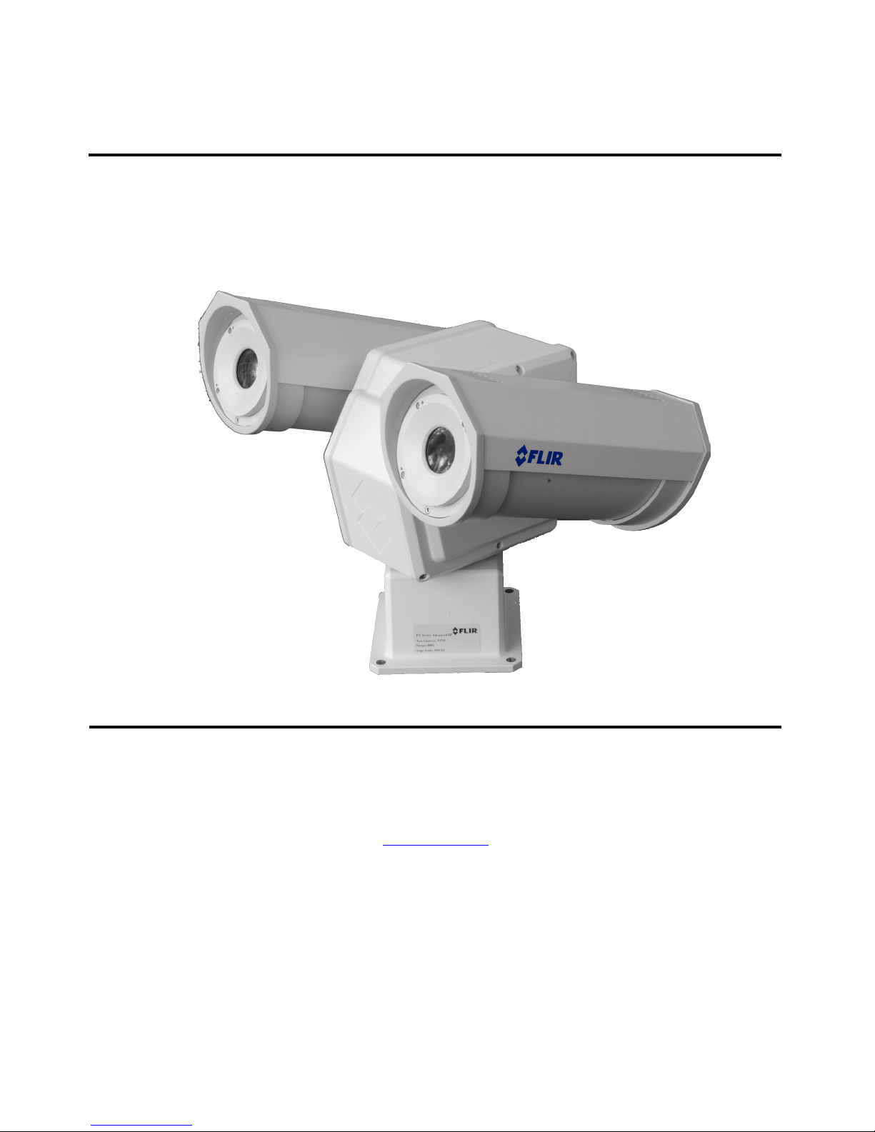
The PT-Series Camera is a multi-sensor camera system on a pan/tilt platform. Combinations of
an infrared thermal imaging camera and a visible-light video camera are intended for outdoor
installations.
Figure 1-1: PT-Series Camera
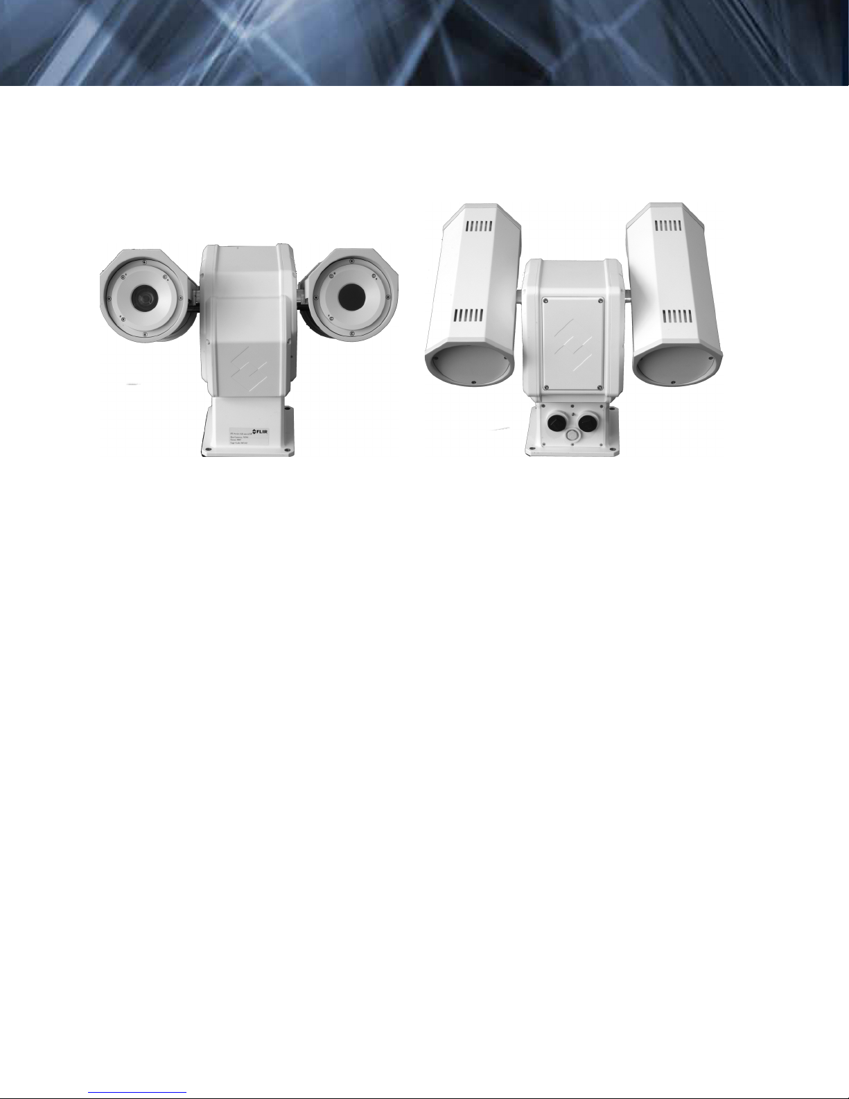
The PT-Series
camera is intended to be mounted on a medium-duty fixed pedestal mount or wall
mount commonly used in the CCTV industry. Cables will exit from the back of the camera
housing. The mount must support up to 45 lbs. (20 KG).
The PT-Series camera is both an analog and an IP camera. The video from the camera can be
viewed over a traditional analog video network or it can be viewed by streaming it over an IP network using MPEG-4, M-JPEG and H.264 encoding. Analog video will require a connection to a
video monitor or an analog matrix/switch. The IP video will require a connection to an Ethernet
network switch, and a computer with the appropriate software for viewing the video stream.
The camera can be controlled through either serial or IP communications providing streaming
video over an IP network.
The camera operates on 21 - 30 VAC or 21 - 30 VDC.
In order to access the electrical connections and install the cables, it is necessary to
temporarily remove the back cover of the camera housing.
1.3 Installation Components
The PT-Series camera includes these standard components:
Multi-sensor Pan/Tilt Camera Unit
FLIR Sensors Manager CD
PT-Series Camera Documentation Package (including installation mounting templates)
1-2 September 2010 427-0032-00-12, version 140
PT-Series Installation Manual 1—PT-Series Camera Installation
The installer will need to supply the following items, the lengths of which are specific to the
installation.
Electrical wire, for system power. Refer to paragraph 1.7 “Electrical Connections and
Schematics” on page 1-5 for additional information)
Camera grounding strap
Coaxial RG59U video cables (BNC connector at the camera end) for analog video
Shielded Category 6 Ethernet cable for control and streaming video over an IP network; and
also for software upgrades.
Optional serial cable for serial communications.
Miscellaneous electrical hardware, connectors, and tools
1.4 Location Considerations
The camera will require connections for power, communications (IP Ethernet, and/or RS232/
RS422}, and video (two video connections may be required for analog video installations).
Important Note
Install all cameras with an easily accessible Ethernet connection to support future software
upgrades.
Refer to paragraph 1.7 “Electrical Connections and Schematics” on page 1-5 for interconnect
diagrams showing system configurations.
Ensure that cable distances do not exceed the Referenced Standard specifications and adhere
to all local and Industry Standards, Codes, and Best Practices.
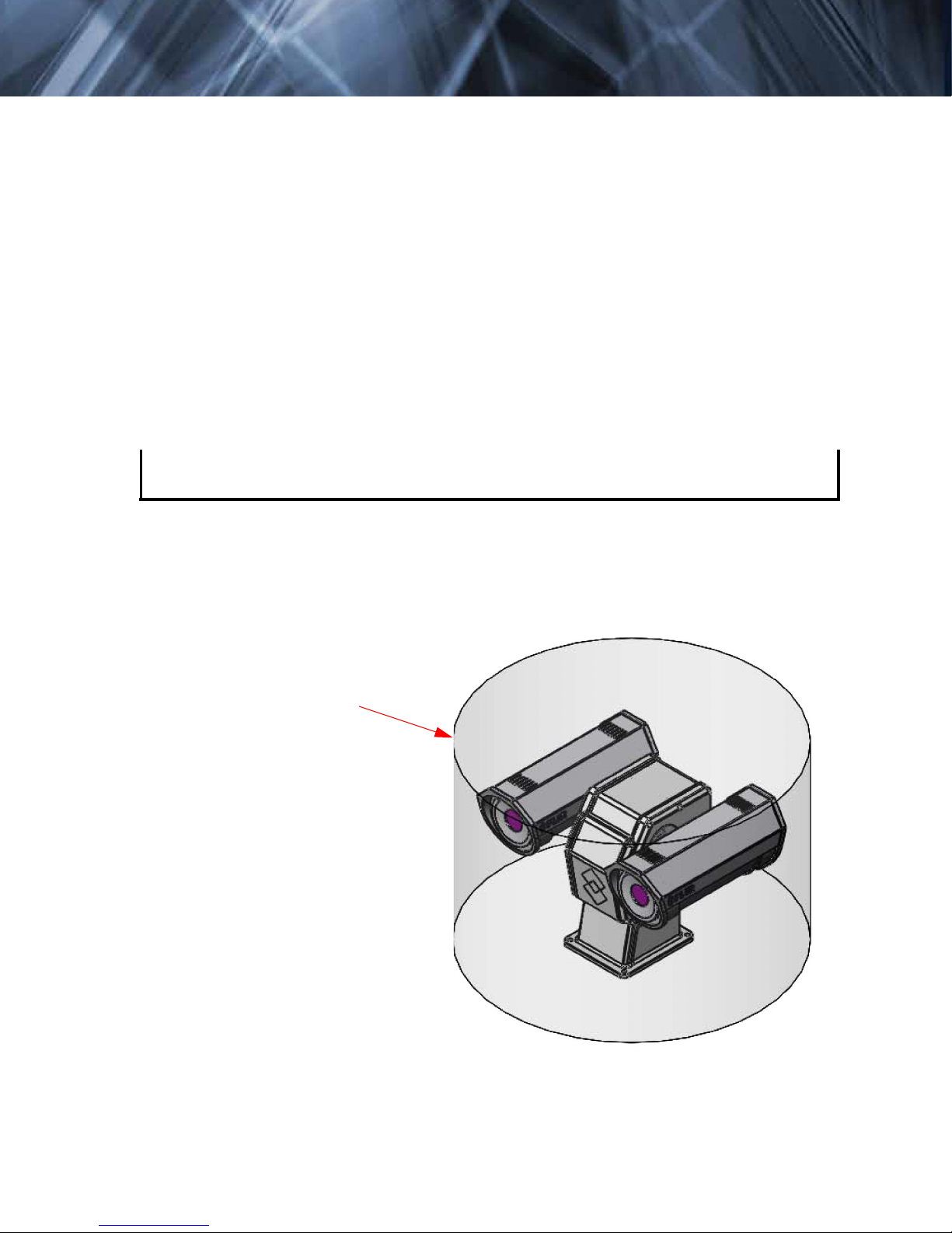
Not to scale
All dimensions in inches
Maximum exclusion cylinder
(Ø25.5” x 17.4” high)
Figure 1-2: PT-Series Pan and Tilt Exclusion Zone
427-0032-00-12, version 140 September 2010 1-3
1—PT-Series Camera Installation PT-Series Installation Manual
1.5 Camera Mounting
Caution!
When lifting the PT-Series camera use the camera body and base, not the tubes.
PT-Series cameras must be mounted upright on top of the mounting surface, with the base
below the camera. The unit should not be hung upside down.
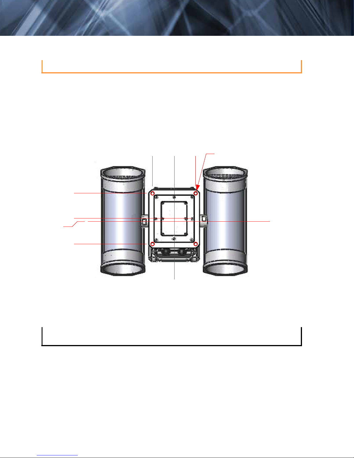
The PT-Series camera can be secured to the mount with four 5/16 or M8 bolts, as shown
below.
Not to scale
All dimensions in inches
2X 3.19 ± .02
0.28
2X 3.19 ± .02
2X 2.72 ± .02
0
Figure 1-3: PT-Series Camera Mounting
0
Pan Axis
2X 2.72 ± .02
4X Ø.354 THRU
Tilt Axis
Once the mounting location has been selected, verify both sides of the mounting surface are
accessible.
Connect and operate the camera as a bench test at ground level prior to mounting the
camera in its final location.
Use a thread locking compound such as Loctite 242 or equivalent with all metal to metal
threaded connections.
Using the template supplied with the camera as a guide, mark the location of the holes for
mounting the camera. If the template is printed, be sure it is printed to scale so the dimensions
are correct.
Once the holes are drilled in the mounting surface, install four (4) 5/16 or M8 bolts through
the base of the camera.
1-4 September 2010 427-0032-00-12, version 140
Important Note
PT-Series Installation Manual 1—PT-Series Camera Installation
1.6 Prior to Cutting/Drilling Holes
When selecting a mounting location for the PT-Series camera, consider cable lengths and cable
routing. Ensure the cables are long enough given the proposed mounting locations and cable
routing requirements.
Use cables that have sufficient dimensions to ensure safety (for power cables) and adequate
signal strength (for video and communications).
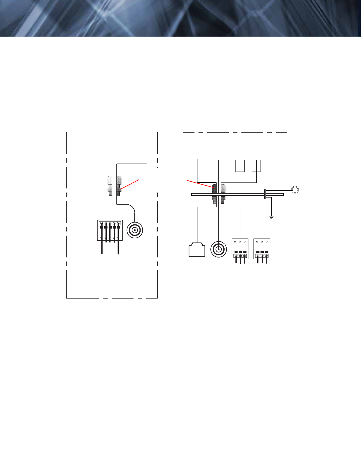
1.7 Electrical Connections and Schematics
Serial Communications
and Main Analog Video
RS232/RS422
20 AWG MAX
RS232 Signals
RS422 Signals
Gland A Camera End
4
5
TD(B)+
Outputs
3
TX+
TD(A)-
{
from camera
2
GND
GND
RD(B)+
Inputs
1
RX+
RD(A)-
{
to camera
Video
3/4” NPT for Cable
Gland or Conduit
Male
BNC
Main
Port
IP Communication, Auxiliary
Analog Video, and Power
Ethernet
Back Cover
Ethernet
Video
16 AWG Shielded
16 AWG Shielded
Male
BNC
Auxiliary
Port
Gland B Camera End
24
VAC/DC
3
24 VAC/DC-
24
VAC/DC
2
1
3
24 VAC/DC-
24 VAC/DC+
Earth Ground
Chassis
GND
2
1
24 VAC/DC+
Earth Ground
Local
GND
427-0032-00-12, version 140 September 2010 1-5
 Loading...