

FLIR PT-602CZ Installation Manual
Installation
Manual
PT-602CZ

© 2018 FLIR Systems, Inc. All rights reserved worldwide. No parts of thi s manual, in whole or in part, may be copied,
photocopied, translated, or transmitted to any electronic medium or machine readable form without the prior written
permission of FLIR Systems, Inc.
Names and marks appearing on the products herein are either registered trademarks or trademarks of FLIR Systems,
Inc. and/or its subsidiaries. All other trademarks, trade names, or company names referenced herein are used for
identification only and are the property of their respective owners.
This product is protected by patents, design patents, patents pending, or design patents pending.
The contents of this document are subject to change.
FLIR Systems, Inc.
6769 Hollister Avenue
Goleta, CA 93117
Support: https://www.flir.com/support-center/support-hq/
Important Instructions and Notices to the User:
Modification of this device without the express authorization of FLIR Systems, Inc., may void the user’s authority
under the FCC Rules to operate this device.
Note 1: This equipment has been tested and found to comply with the limits for a Class A digital device, pursuant to
part 15 of the FCC Rules. These limits are designed to provide reasonable protection against harmful interference
when the equipment is operated in a commercial environment. This equipment generates, uses, and can radiate radio
frequency energy and, if not installed and used in accordance with the instruction manual, may cause harmful
interference to radio communications. Operation of this equipment in a residential area is likely to cause harmful
interference in which case the user will be required to correct the interference at his own expense. Shielded cables
must be used to connect this device to other devices.
Note 2: If ferrites are supplied with this equipment, the equipment was tested for compliance with the FCC limits for a
Class A digital device using power cables with the ferrites installed. When connecting one or two power cables to the
equipment, the supplied ferrites must be used with this equipment.
Industry Canada Notice:
This Class A digital apparatus complies with Canadian ICES-003.
Avis d’Industrie Canada:
Cet appareil numérique de la classe A est conforme à la norme NMB-003 du Canada.
Proper Disposal of Electrical and Electronic Equipment (EEE)
The European Union (EU) has enacted Waste Electrical and Electronic Equipment Directive 2002/96/
EC (WEEE), which aims to prevent EEE waste from arising; to encourage reuse, recycling, and
recovery of EEE waste; and to promote environmental responsibility.
In accordance with these regulations, all EEE products labeled with the crossed out wheeled bin
either on the product itself or in the product literature must not be disposed of in regular rubbish bins,
mixed with regular household or other commercial waste, or by other regular municipal waste
collection means. Instead, and in order to prevent possible harm to the environment or human health,
all EEE products (including any cables that came with the product) should be responsibly discarded or recycled.
To identify a responsible disposal method nearby, please contact a local waste collection or recycling service, the
original place of purchase or product supplier, or the responsible government authority in the area. Business users
should contact their supplier or refer to their purchase contract.
427-0038-00-12 Version 110 March 2018 2

Table of Contents
Ta bl e o f C on te nts
PT-602CZ Camera Installation
1.1 Camera Overview ......................................................................................................................5
1.2 Installation Overview ..................................................................................................................5
1.2.1 Camera Connection Options ............................................................................................5
1.2.2 Serial Communications Overview ....................................................................................6
1.2.3 Supplied Components ......................................................................................................6
1.2.4 Required Components .....................................................................................................6
1.3 Location Considerations ............................................................................................................7
1.3.1 Bench Testing ..................................................................................................................7
1.3.2 Prior to Cutting/Drilling Holes ...........................................................................................7
1.4 Camera Mounting ......................................................................................................................7
1.4.1 Galvanic Isolation .............................................................................................................8
1.4.2 Earth Ground Connection .................................................................................................8
1.4.3 Installation of Camera and Galvanic Isolation Kit .............................................................9
1.5 Camera Connections ...............................................................................................................10
1.5.1 Removing the Back Cover ..............................................................................................10
1.5.2 Connecting power ..........................................................................................................12
1.5.3 Video Connections .........................................................................................................12
1.5.4 Ethernet Connection .......................................................................................................12
1.5.5 Serial Connection ...........................................................................................................12
1.5.6 Serial Communications Settings - Hardware DIP Switches ...........................................13
1.5.7 Cable Gland Sealing ......................................................................................................15
1.6 PT-602CZ Camera Specifications ...........................................................................................16
Basic Operation and Configuration
2.1 IP Camera, ONVIF Profile S Compliant ...................................................................................18
2.1.1 Serial and/or IP Communications ...................................................................................18
2.1.2 Server Configuration ......................................................................................................18
2.2 Camera Bench Test .................................................................................................................18
2.2.1 Set IP Address using the FLIR Discovery Network Assistant (DNA) .............................19
2.2.2 Log into the Camera Web Page .....................................................................................20
2.2.3 Live Video Page .............................................................................................................21
2.2.4 Camera Control and Status ............................................................................................22
2.3 Basic Camera Configuration ....................................................................................................24
2.3.1 Expert and Admin Accounts ...........................................................................................24
2.3.2 Setup Menu ....................................................................................................................24
2.3.3 Maintenance Menu .........................................................................................................28
2.4 Thermal Imaging Overview ...................................................................................................... 42
2.5 Troubleshooting Tips ...............................................................................................................44
2.6 Restoring the Factory Settings .................................................................................................46
Serial Address: Decimal To Binary Conversion
3.1 Address Conversion Table .......................................................................................................47
427-0038-00-12, Version 110 March 2018 3

1 PT-602CZ Camera Installation
The PT-602CZ pan/tilt thermal security camera for medium- to long-range applications can be used
with traditional analog video installations or IP video networks. It incorporates a high-sensitivity thermal
camera and a long-range daylight camera with a precision pan/tilt platform.
The PT-602CZ camera includes a cooled, high-performance thermal imager which is optimized for
medium- to long-range surveillance.The thermal imager brings together a sensitive third generation
mid-wave focal plane array (FPA) detector with 640x512 pixels, powerful video-processing electronics,
and continuous zoom optics incorporated into a compact package.
This manual describes the installation of the PT-602CZ cameras. If help is needed during the
installation process, please log on to https://www.flir.com/support-center/support-hq/ for support. All
installers and integrators are encouraged to take advantage of the training offered by FLIR; visit
https://www.flir.com/support-center/training/ for more information.
This manual includes the following topics:
• Installation overview
• Mounting the camera and its components
• Connecting the electronics
• Bench testing the camera
• Basic configuration and operation of the camera
• Camera specifications
For safety, and to achieve the highest levels of performance from the PT-602CZ camera system,
always follow the warnings and cautions in this manual when handling and operating the camera
system.
Warning!
If mounting the PT-602CZ camera on a pole, tower or any elevated location, use industry standard
safe practices to avoid injuries.
Caution!
Except as described in this manual, do not open the PT-602CZ camera for any reason. Disassembly
of the camera (including removal of the cover) can cause permanent damage and will void the
warranty.
Be careful not to leave fingerprints on the PT-602CZ camera’s infrared optics.
The PT-602CZ camera requires a power supply of 24 Volts nominal. Operating the camera outside of
the specified input voltage range or the specified operating temperature range can cause permanent
damage.
PT-Series Camera Mechanical Interface Control Document (ICD)
(FLIR Doc # 427-0032-00-19)—available from the FLIR website, provides further details regarding
mechanical dimensions and mounting for the PT-602CZ camera.
427-0038-00-12, Version 110 March 2018 4
1 PT-602CZ Camera Installation
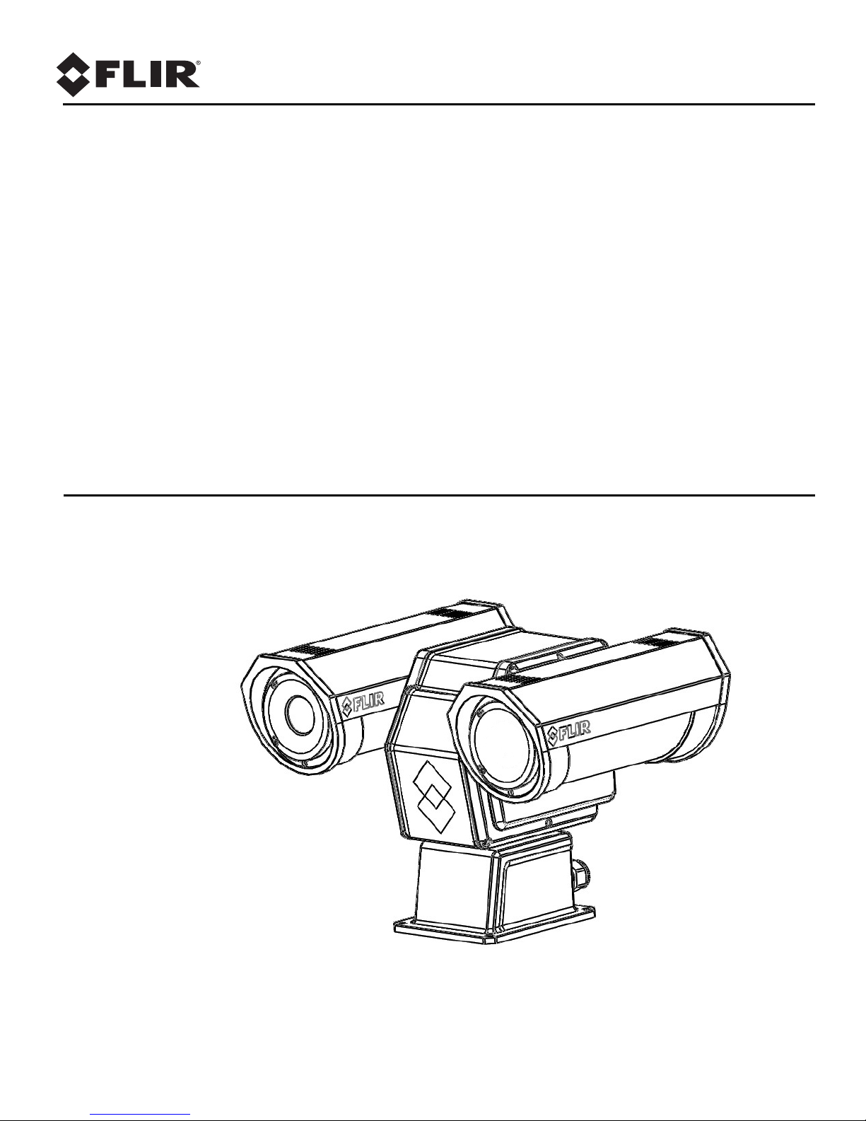
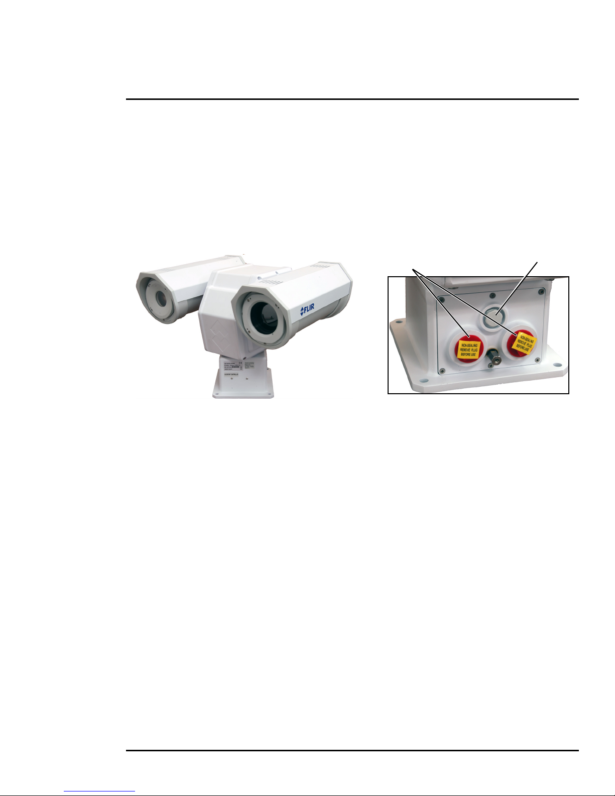
Figure 1-1: PT-602CZ
Shipping plugs only Remove before installing
Vent
1.1 Camera Overview
The PT-602CZ camera is both an analog and an IP camera. The video from the camera can be viewed
over a traditional analog video network or it can be viewed by streaming it over an IP network using
MPEG-4, M-JPEG, or H.264 encoding. Analog video will require a connection to a video monitor or an
analog matrix/switch. The IP video will require a connection to an Ethernet network switch and a
computer with the appropriate software for viewing the video stream.
1.2 Installation Overview
The PT-602CZ camera is intended to be mounted outdoors on a medium-duty fixed pedestal mount or
wall mount commonly used in the CCTV industry. Cables will exit from the back of the camera housing.
The mount must support up to 45 lbs (20 KG). The camera can be controlled through either serial or IP
communications. The camera operates on 21 Vac to 30 Vac or 21 Vdc to 30 Vdc. In order to access
the electrical connections and install the cables, it is necessary to temporarily remove the back cover
of the camera housing. Ensure the back cover is replaced in the same orientation, with the two cable
glands below the central pressure equalization vent.
1.2.1 Camera Connection Options
Camera connections are made through water-tight cable gland seals on the rear of the camera. Refer
to
Cable Gland Sealing, pg. 15 to ensure the glands are used correctly and the connections are
properly sealed.
The PT-602CZ Camera produces both analog and digital (IP) video output. Analog video will require at
least one connection to a video monitor or an analog video matrix switch. In most analog installations,
two video connections will be used—one for the thermal camera video, and one for the daylight
camera video. The camera provides two BNC connectors for these video channels.
An Ethernet connection is provided for IP video streaming and for command and control
communications using a web browser.
For analog installations that are not using Ethernet/IP, a serial cable (RS232 or RS422) can be
connected and used for command and control communications, supporting either Pelco D or Bosch
protocols. It is recommended an Ethernet cable should also be installed to allow easy remote access
for camera configuration, operation, and troubleshooting.
427-0038-00-12 Version 110 March 2018 5

1 PT-602CZ Camera Installation
1.2.2 Serial Communications Overview
The installer must decide if the serial communications settings will be configured via hardware (DIP
switch settings) or software (default). If the camera has an Ethernet connection, then generally it is
easier (and more convenient) to make configuration settings via software. Then configuration changes
can be made over the network without physically accessing the camera. Also the settings can be
saved to a file and backed up or restored as needed.
If the camera is configured via hardware, then configuration changes in the future may require
accessing the camera on a tower or pole, dismounting it, and removing the back and so on. If the
camera does not have an Ethernet connection, the DIP switches must be used to set the serial
communication options.
1.2.3 Supplied Components
The PT-602CZ camera ships with these standard components:
• Multi-sensor pan/tilt camera unit
• Galvanic isolation kit (PN 4204960)
• Cable glands and spare parts kit
1.2.4 Required Components
The installer will need to supply the following items; the lengths are specific to the installation.
• Power supply
• Electrical wire, for system power; up to 100’ (3-conductor, shielded, gauge determined by cable
length and supply voltage. Refer to
Figure 1-4 on page 11 for additional information.)
• Camera grounding strap
• Coaxial RG59U video cables (BNC connector at the camera end) for analog video
• Shielded category 6 Ethernet cable for control, streaming video, and for software updates.
• Serial cable for serial communications—optional
• Miscellaneous electrical hardware, camera mount (with stainless steel washers and bolts),
connectors, and tools
427-0038-00-12 Version 110 March 2018 6

1 PT-602CZ Camera Installation
1.3 Location Considerations
Install the camera in a location that will allow access for regular periodic cleaning (fresh water rinse),
inspection of mounting integrity and mechanical soundness, and preventative maintenance. Ensure
the camera and the camera mount are routinely inspected on a periodic basis.
The camera will require connections for power, communications (IP Ethernet, serial), and video
(analog, IP digital).
• Install all cameras with an easily accessible Ethernet connection to support future software
updates.
• Ensure that cable distances do not exceed the specifications and that cables adhere to all local
and industry standards, codes, and best practices.
1.3.1 Bench Testing
Connect the power, video, serial, and Ethernet connections and confirm that the video is displayed on
a monitor when the power is turned on. Confirm the camera can be controlled by moving it (pan/tilt).
For configuration and basic setup information using the onboard web server, refer to
and Configuration, pg. 18.
Basic Operation
1.3.2 Prior to Cutting/Drilling Holes
When selecting a mounting location for the PT-602CZ camera, consider cable lengths and cable
routing. Ensure the cables are long enough given the proposed mounting locations and cable routing
requirements.
Use cables that have sufficient dimensions to ensure safety (for power cables) and adequate signal
strength (for video and communications).
1.4 Camera Mounting
Caution!
Always use stainless steel washers on the four camera base mounting holes, especially in locations
where the camera base is exposed to a damp or salt environment. Ensure that the camera base is
electrically isolated and properly grounded when it is secured to its mount. Contact between the
stainless steel fasteners and any bare aluminum may cause galvanic corrosion which will shorten
the life of the installation and may void the camera warranty. Following this procedure is critical to
maintaining the warranty on your PT-602CZ product.
Galvanic isolation is critical in preventing corrosion. Proper installation of galvanic isolation pad and
washers is important for long product life.
There are two critical steps related to proper galvanic isolation camera mounting:
• Installation of galvanic isolation kit
• Proper grounding (bonding) to earth ground
427-0038-00-12 Version 110 March 2018 7
1 PT-602CZ Camera Installation
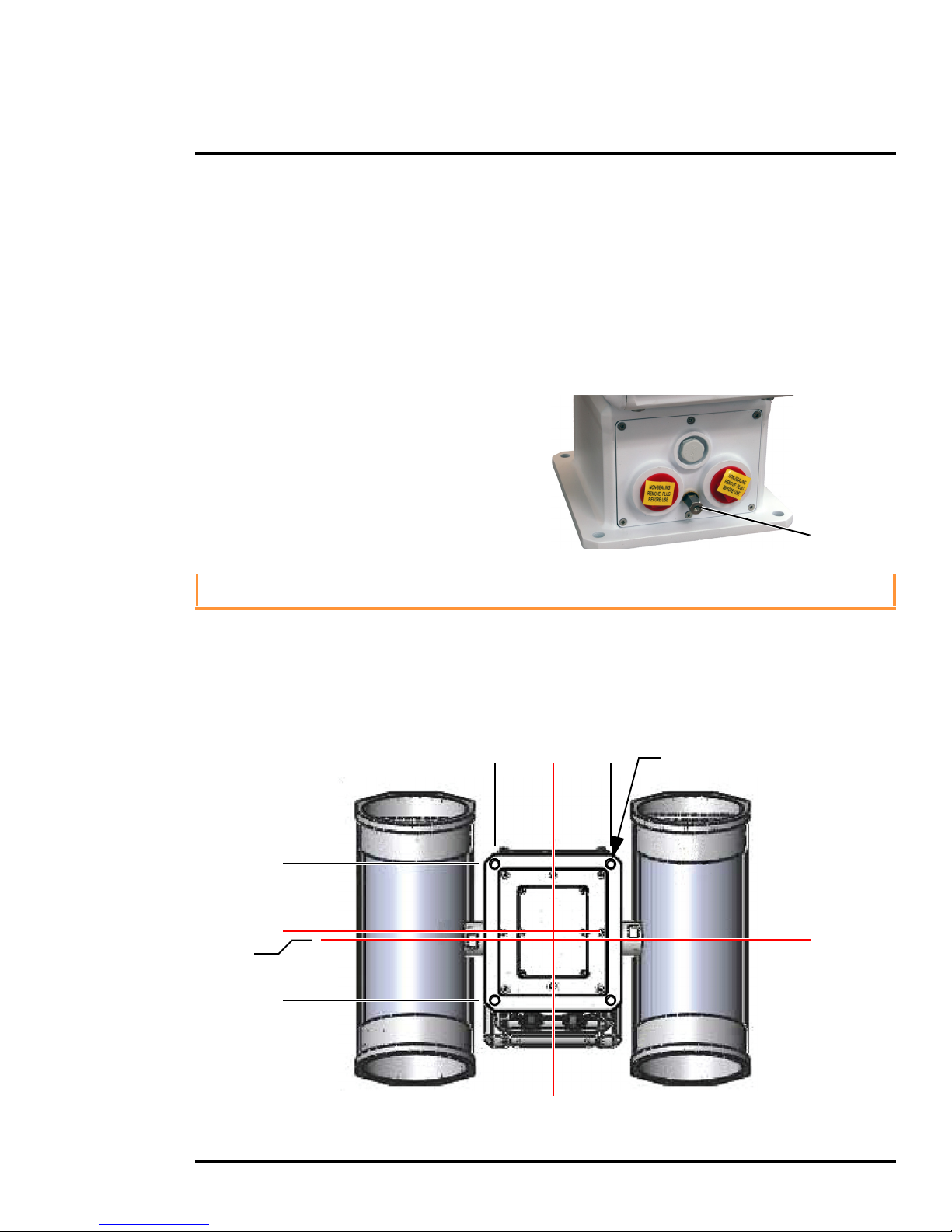
Ground Lug
Figure 1-2: PT-602CZ Camera Mounting
Not to scale
0
0.28
All dimensions in inches
0
2X 3.19 ± .02
2X 3.19 ± .02
2X 2.72 ± .02
2X 2.72 ± .02
4X Ø.354 THRU
Pan Axis
Tilt Axis
1.4.1 Galvanic Isolation
The Galvanic Isolation Kit (FLIR PN 4204960) is for use with all PT-602CZ cameras (PT-3XX, PT-6XX,
A310-PT, PT-602CZ). The isolation plate and nylon shoulder or flat washers provide electrical isolation
between the stainless steel fasteners and the aluminum camera base, and electrically isolates the
complete PT-602CZ camera from the customer mount.
Galvanic isolation is critical in preventing corrosion. Proper installation of galvanic isolation pad and
washers is important for long product life. Refer to
9 for specific instructions.
1.4.2 Earth Ground Connection
Earth ground connection is very important to
protect PT-602CZ from surge induced failures
and corrosion caused by stray current/ground
loops. Attach ground wire (16AWG or larger) to
ground lug on access panel. Use the large hex
nut to secure ground wire to stud on access
panel. Ground stud is #8-32 thread.
Installation of Camera and Galvanic Isolation Kit, pg.
Caution!
When lifting the PT-602CZ camera use the camera body and base, not the tubes.
PT-602CZ cameras must be mounted upright on top of the mounting surface, with the base below the
camera. The unit should not be hung upside down.
427-0038-00-12 Version 110 March 2018 8

1 PT-602CZ Camera Installation
Once the mounting location has been selected, verify both sides of the mounting surface are
accessible.
Use a thread locking compound such as Loctite 242 or equivalent with all metal to metal threaded
connections.
Once the holes are drilled in the mounting surface, install four (4) stainless steel 5/16 or M8 bolts with
stainless steel washers and lock washers through the base of the camera.
1.4.3 Installation of Camera and Galvanic Isolation Kit
Important Safeguards and Warnings
• Installation and servicing should be done by qualified installation and service personnel only.
• Installation should be done according to all local and national electrical and mechanical codes,
using only approved materials.
• Use stainless steel hardware to fasten mounts to outdoor surfaces.
• To prevent damage from water leakage when installing outdoors, apply sealant around the bolt
holes between the mount and the mounting surface.
Caution!
Following this procedure is critical to maintaining the warranty on your PT-602CZ product.
Failure to follow these instructions can potentially void the camera warranty.
Tabl e 1-1: Kit Contents
Description Qty
Isolation plate
M8 nylon flat washer
M8 nylon shoulder washer
M8 split washer, S.S.
M8 washer, S.S.
Tef-Gel TG .25, 3 cc syringe
a. Use the alternate nylon flat washers and Tef-Gel lubricant on fasteners for PT-602CZ camera bases with
mounting holes that are too small to accept the shoulder washers. A syringe of Tef-Gel may be supplied in
the mounting kit when the nylon flat washer is expected to be required.
a
a
1
6
6
6
6
optional
Two extra pieces of each attaching part are
supplied in the kit.
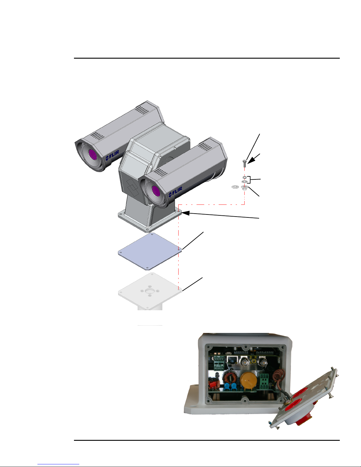
Step 1 Determine the correct positioning of the isolation plate (See Figure 1-3 on page 10).
Step 2 Place the isolation plate and the camera on the mounting structure aligning the bolt holes or
studs.
Step 3 Install nylon shoulder washers (4x) or alternate nylon flat washers (4x) onto camera base.
If using nylon flat washers, apply a generous coat of Tef-Gel filling all gaps and voids.
Step 4 Secure the camera using 5/16” or M8 fasteners (4x) with stainless steel flat washers and
split washers on top of the nylon washers.
427-0038-00-12 Version 110 March 2018 9
1 PT-602CZ Camera Installation
M8 or 5/16” fasteners (not supplied)
4 places, minimum length 1 in.
M8 split lock washer (4 places)
M8 flat washer (4 places)
Figure 1-3: PT-602CZ Galvanic Isolation Kit (4204960)
M8 nylon shoulder washer or
isolation plate
example mounting structure
(dependent on mounting structure)
nylon flat washer (4 places)
(FLIR PN 500-0461-00)
If using nylon flat washers,
apply a generous coat of Tef-Gel
If using nylon flat washers,
apply a generous coat of Tef-Gel
filling all gaps and voids.
filling all gaps and voids.
(4 places)
(4 places)
Step 5 Ensure the camera is properly grounded. FLIR requires using a 14 AWG to 16 AWG
grounding strap anchored to the ground lug on the back plate of the camera housing and
then terminated to the nearest earth-grounding point.
1.5 Camera Connections
1.5.1 Removing the Back Cover
Use a 2.5 mm hex key to loosen the
captive screws and remove the cover,
exposing the connections at the back of
the camera. There is a grounding wire
connected between the case and the
back cover
427-0038-00-12 Version 110 March 2018 10
1 PT-602CZ Camera Installation
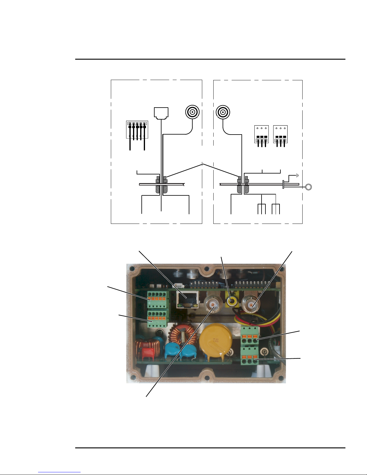
Gland A Camera End
Serial and IP Communications
Main Analog Video
Gland B Camera End
Auxiliary Analog Video and Power
EthernetSerial
Control
Male
BNC
Video
Ethernet
RS232
RS422
20 AWG MAX
RX+
TX+
GND
RD(A)-
GND
RD(B)+
TD(A)-
TD(B)+
1
2
3
4
5
{
Main
Port
Back Cover
16 AWG Shielded
16 AWG Shielded
Local
GND
24
VAC/DC
24
VAC/DC
1
2
3
1
2
3
24 VAC/DC+
24 VAC/DC-
Earth Ground
24 VAC/DC+
24 VAC/DC-
Earth Ground
{
{
Chassis
GND
Video
Male
BNC
Auxiliary
Port
Analog Video
(monitoring output only)
Camera Power
IP Network Analog Visible Video
Analog Infrared Video
Figure 1-4: PT-602CZ Camera Connections
Heater Power
Not used
Serial Connector
for local control
3/4” NPT for Cable
Gland or Conduit
427-0038-00-12 Version 110 March 2018 11

1 PT-602CZ Camera Installation
1.5.2 Connecting power
The camera itself does not have an on/off switch. Generally the PT-602CZ camera will be connected to
a circuit breaker and the circuit breaker will be used to apply or remove power to the camera. If power
is supplied to it, the camera will be in one of two modes: Booting Up or Powered On.
The power cable supplied by the installer must use wires that are sufficient size gauge (16 AWG
recommended) for the supply voltage and length of the cable run, to ensure adequate current carrying
capacity. Always follow local building codes!
Ensure the camera is properly grounded. Typical to good grounding practices, the camera chassis
ground should be provided using the lowest resistance path possible. FLIR requires using a grounding
strap anchored to the grounding lug on the back plate of the camera housing and connected to the
nearest earth-grounding point.
Note
The terminal blocks for power connections will accept a maximum 16 AWG wire size.
1.5.3 Video Connections
The analog video connections on the back of the camera are BNC connectors. The camera also
provides an RCA video connector that can be used to temporarily monitor the video output.
The video cables used should be rated as RG59U or better to ensure a quality video signal.
Note
Insert the cable through the cable glands on the enclosure before terminating and connecting them.
In general, the terminated connectors will not fit through the cable gland. If terminated, it is possible
to make a clean and singular cut in the gland seal to install the cable into the gland seal.
1.5.4 Ethernet Connection
The cable gland seal is designed for use with shielded category 6 Ethernet cable.
Note
Insert the cable through the cable glands on the enclosure before terminating and connecting them.
In general, the terminated connectors will not fit through the cable gland. If terminated, it is possible
to make a clean and singular cut in the gland seal to install the cable into the gland seal.
1.5.5 Serial Connection
For serial communications, it is necessary to set the parameters such as the signaling standard (RS232 or RS-422), baud rate, number of stop bits, parity and so on. It is also necessary to select the
communication protocol used (either Pelco D or Bosch) and the camera address. By default, the serial
interface uses Pelco D, RS-422 standard, 9600 baud rate, 8/1/none, and address 1.
Note
Typical Bosch systems operate using a biphase connection. FLIR cameras do not accept biphase
signals directly. It may be necessary to install a biphase converter in order to use the Bosch protocol.
Connect the wires of the serial cable as show in Figure 1-4. When using the RS-422 standard, ensure
the transmit pair of the camera goes to the receive pair of the other device, and vice versa.
427-0038-00-12 Version 110 March 2018 12
1 PT-602CZ Camera Installation
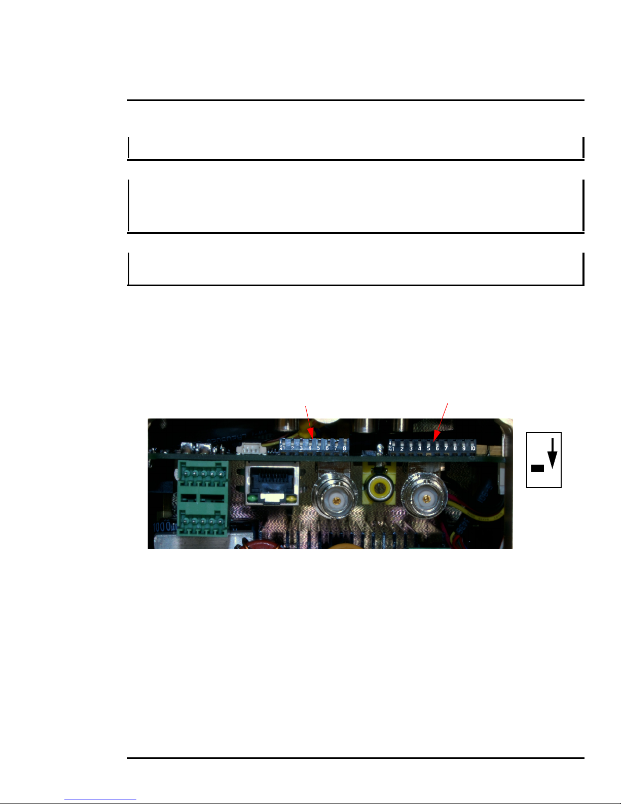
Figure 1-5: PT-602CZ Camera Configuration
SW102 SW103
Off
On
Switch
Position
Note
The terminal blocks for serial connections will accept a maximum 20 AWG wire size.
Note
The serial communications parameters for the PT-602CZ camera are set or modified either via
hardware DIP switch settings or via software, through a web browser interface. A single DIP switch
(SW103-9), Software Override determines whether the configuration comes from the hardware DIP
switches or the software settings.
Note
The DIP switches are only used to control serial communications parameters. Other settings, related
to IP camera functions and so on, must be modified via software (using a web browser).
1.5.6 Serial Communications Settings - Hardware DIP Switches
The camera has two blocks of DIP switches that are used to configure the serial communications
settings. One block of switches has 8 switches and is used to set the serial address (or ID) of the
camera. The other block of switches has 10 switches and is used to set baud rate, hardware protocol
(RS-232 or RS-422), serial protocol (Pelco D or Bosch), and Software Override.
The figure below shows the locations of dip switches SW102 and SW103.
When the Software Override DIP switch is set to the Off position (as it is by default), all of the other DIP
switches will be ignored, and configuration changes must be made through software. If the switch is
set to the On position, all configuration settings related to serial communications are made with the
DIP switches, and changes that are made via software (with a web browser) will be ignored.
Serial Address: Use the block of switches on the left (SW102) to set the serial address of the
camera. The available range of values is from decimal 1 to 255. The dip switches are interpreted as a
binary number, with switch 1 representing the least significant bit (the switches are in the reverse order
of the bits). For convenience, a table of serial addresses and their binary equivalents is included at the
end of the manual. Refer to
Serial Address: Decimal To Binary Conversion, pg. 47
427-0038-00-12 Version 110 March 2018 13

1 PT-602CZ Camera Installation
Tab l e 1-2: Dip Switch Address/ID Settings—SW101
ID
1 On Off Off Off Off Off Off Off
2 Off On Off Off Off Off Off Off
3 On On Off Off Off Off Off Off
… … … … … … … … …
255 On On On On On On On On
Sw 1
LSB
Sw 2 Sw 3 Sw 4 Sw 5 Sw 6 Sw 7
Other Serial Communication Parameters: The tables below defines the switch locations, bit
numbering and on/off settings used in controlling the other serial communication parameters.
Tab l e 1-3: Dip Switch Settings—SW103
Settings Description
Baud rate: This is the baud rate of the system user serial
port. The available values are 2400, 4800, 9600, 19200
kbaud.
Camera Control Protocol: This is the communication
protocol selected for the system when operating over the
serial port. The available protocols are Pelco-D and
Bosch.
Serial Communication Standard: This determines the
electrical interface selected for the user serial port. The
available settings are RS422 and RS232.
Bit 1 Bit 2
OFF OFF
ON OFF
OFF ON
ON ON
Bit 3 Bit 4
OFF OFF
ON OFF
OFF ON
ON ON
Bit 5 Bit 6
OFF OFF
ON OFF
OFF ON
ON ON
Bit 7 Bit 8
2400
4800
9600
19200
Pelco-D
NA
Bosch
NA
NA
RS422
RS232
N/A
Sw 8
MSB
Not Used
Software Override DIP Switch: This setting determines
whether the system will use software settings for
configuration or if the dip switch settings will override the
software settings. Default is Off.
Not Used
427-0038-00-12 Version 110 March 2018 14
X X
X X
X X
X X
Bit 9
OFF
ON
Bit 10
X
Software select
Hardware select
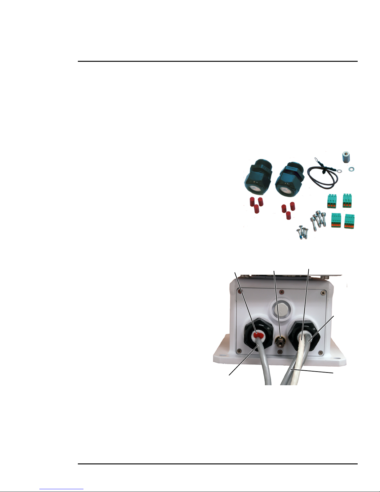
1 PT-602CZ Camera Installation
Camera
Serial Control
Ethernet
Heater
Gland seal plugs
Ground
Lug
Power
Power
1.5.7 Cable Gland Sealing
Proper installation of cable sealing glands and use of appropriate elastomer inserts is critical to long
term reliability. Cables enter the camera mount enclosure through liquid-tight compression glands. Be
sure to insert the cables through the cable glands on the enclosure before terminating and connecting
them (the connectors will not fit through the cable gland). Leave the gland nuts loosened until all cable
installation has been completed. Inspect and install gland fittings in the back cover with suitable leak
sealant and tighten to ensure water tight fittings. Teflon tape or pipe sealant (i.e. DuPont RectorSeal
T™) are suitable for this purpose.
Cable Glands and Spare Parts Kit
The kit contains the two 3/4” cable glands and gland
seal plugs required for non-conduit installations.
The remaining parts included in the kit are:
• a spare ground wire
• a spare ground nut and lock washer
• two spare power terminal block plugs
• two spare serial port terminal block plugs
• four spare F-Series back cover screws
• four spare PT-Series back cover screws
Cable Gland Seal Inserts
Cables may be between 0.23" to 0.29" OD. Up
to six cables may be installed. Plugs are
required for the hole(s) not being used. The
photograph at the right shows two power
cables, an Ethernet cable, a serial control cable
(no analog video is installed), and two gland
seal plugs.
If non-standard cable diameters are used, it
may be necessary to locate or fabricate the
appropriate insert to fit the desired cable. FLIR
Systems, Inc. does not provide cable gland
inserts other than what is supplied with the
system.
427-0038-00-12 Version 110 March 2018 15
 Loading...