

Page 1

Photon Block 2
User Guide
412-0035-00-10
Version 100
FLIR Systems
Indigo Operations
70 Castilian Dr.
Goleta, CA 93117-3027
805 964-9797 FAX 805 685-2711
www.indigosystems.com
Page 2

Photon User Guide 412-0035-00-10 Version 100
TABLE OF CONTENTS
1 INTRODUCTION................................................................................................................. 4
2 PHOTON SPECIFICATIONS ............................................................................................ 4
3 UNPACKING YOUR PHOTON CAMERA...................................................................... 5
4 OPTIONAL PHOTON ACCESSORIES............................................................................ 6
5 OVERVIEW OF THE PHOTON ELECTRICAL INTERFACE.................................... 6
INPUT POWER............................................................................................................................... 8
ANALOG VIDEO OUTPUT ............................................................................................................. 8
COMMAND AND CONTROL CHANNEL........................................................................................... 9
DIGITAL DATA CHANNEL ............................................................................................................ 9
EXTERNAL SYNCHRONIZATION.................................................................................................... 9
Voltage Outputs .................................................................................................................... 10
Input/Output Pins.................................................................................................................. 10
6 BASIC OPERATION OF THE PHOTON CAMERA.................................................... 11
7 REMOTE CONTROL OF THE PHOTON CAMERA .................................................. 12
INSTALLATION OF PHOTON CONTROL PANEL SOFTWARE .......................................................... 13
CONNECTING PHOTON TO A PC VIA THE I/O MODULE ............................................................... 13
TROUBLESHOOTING THE COMMAND & CONTROL LINK ............................................................. 13
OPERATION OF THE PHOTON CONTROL PANEL .......................................................................... 14
7.1.1 Control Panel Camera Tab................................................................................... 15
7.1.2 Control Panel Video Tab ...................................................................................... 19
7.1.3 Control Panel AGC Tab........................................................................................ 25
7.1.4 Control Panel About Tab...................................................................................... 28
8 PHOTON DIGITAL DATA CHANNEL.......................................................................... 29
SING THE DIGITAL DATA CHANNEL ........................................................................................ 29
U
9 PHOTON PHYSICAL INTERFACE ............................................................................... 30
DIMENSIONED DRAWINGS ......................................................................................................... 30
WEIGHT ..................................................................................................................................... 30
M
OUNTING................................................................................................................................. 31
APPENDIX A: PIN-OUT DEFINITIONS ............................................................................... 37
I/O MODULE .............................................................................................................................. 37
COPYRIGHT NOTICE © FLIR SYSTEMS CORPORATION 2006
2
Page 3

Photon User Guide 412-0035-00-10 Version 100
Cautions:
• Do not remove the camera cover. Disassembly of the camera (including removal of the
cover) can cause permanent damage and will void the warranty.
• Operating the camera outside of the specified input voltage range or the specified
operating temperature range can cause permanent damage.
• The camera is not sealed. Avoid exposure to dust and moisture and replace the lens cap
when not in use.
• Do not image extremely high intensity radiation sources, such as the sun, lasers, arc
welders, etc.
• The camera is a precision optical instrument and should not be exposed to excessive
shock and/or vibration. Refer to the Product Specification (ISC doc. 102-0005-09) for
detailed environmental requirements.
• This camera contains static-sensitive electronics and should be handled appropriately.
• If you have questions that are not covered in this manual, or need service, contact
Customer Support at (805) 964-9797 for additional information prior to returning a
camera.
3
Page 4
Photon User Guide 412-0035-00-10 Version 100
1 INTRODUCTION
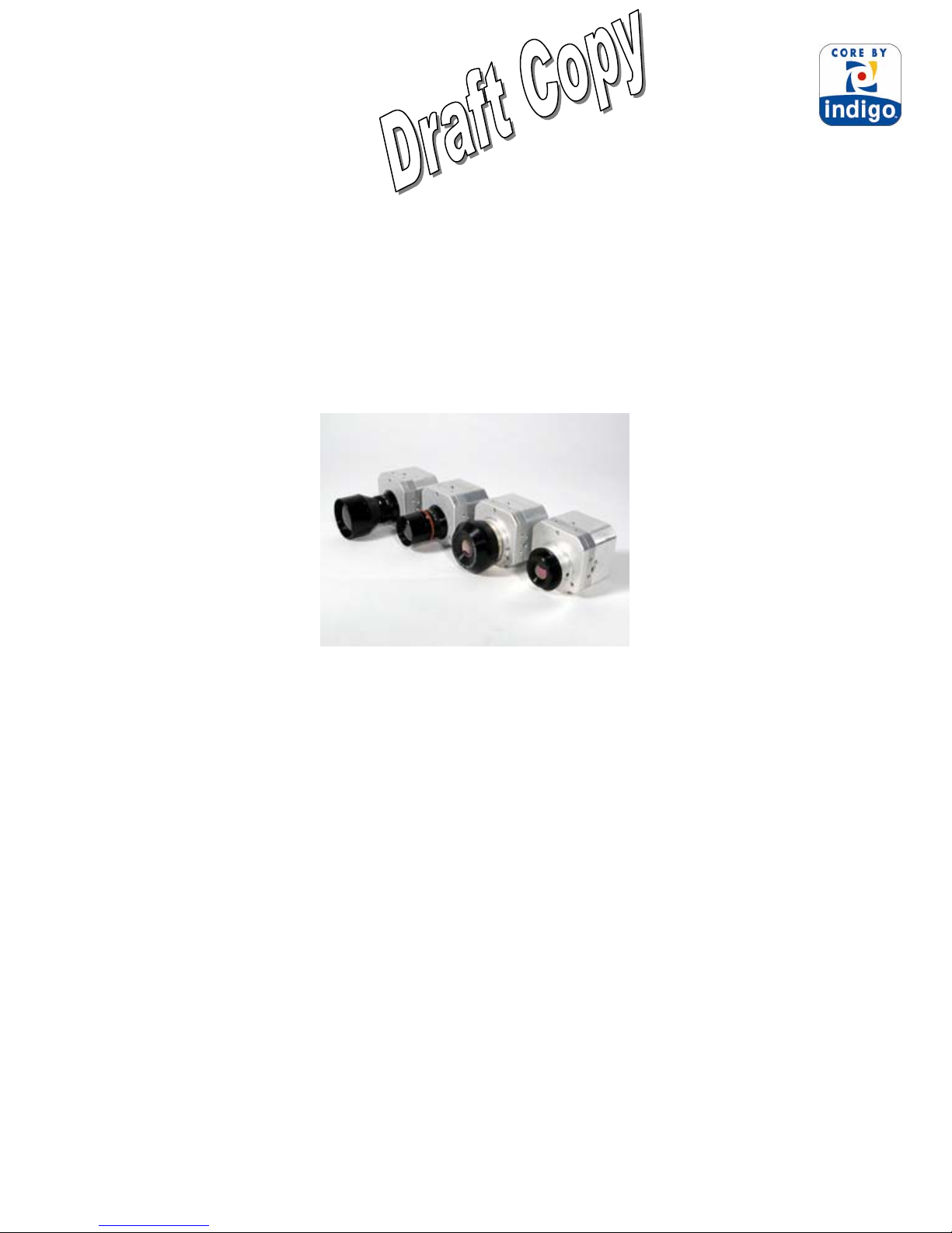
The Photon is a long-wavelength (7.5 – 13.5 microns) uncooled microbolometer camera designed
for infrared imaging applications that demand absolute minimum size, weight, and power
consumption. It is available with five different lens options: 14.25 mm focal length (50° H field of
view or FOV), 19 mm focal length (36° HFOV), 30 mm (23° HFOV), 35 mm (20° HFOV) or 50
mm (14° HFOV). The camera provides “power-in, video-out” capability, which means that one
need only apply input voltage to receive analog video. For those applications demanding more
advanced control the Photon includes a serial interface (RS-232) for transmitting camera
commands and receiving status. Photon provides digital data interface via a parallel interface.
Figure 1: Photon 50 mm, 30 mm, 19 mm and 14.25 mm
2 PHOTON SPECIFICATIONS
• 324 (H) x 256 (V) uncooled microbolometer sensor array, 38 x 38 micron pixels
• Input power range: 5.0 – 24.0 VDC
• Power Consumption: 1.5 Watts (nominal at room temperature with 8V input)
• Operating Temperature Range: -40°C to +75°C external temp range
• Dimensions: see detailed drawings in Section 9
• Weight: approx 97 grams for camera core
• Analog video output: NTSC (PAL optional)
• Remote interface: RS-232 (Control Panel software included.)
• Included features:
o 2X Digital Zoom with electronic pan/tilt
o Digital Detail Enhancement
Note: These specifications are subject to change without notice. See the Electrical Interface
Control Document (ISC doc. 102-1238-41) for detailed interface descriptions.
4
Page 5
Photon User Guide 412-0035-00-10 Version 100
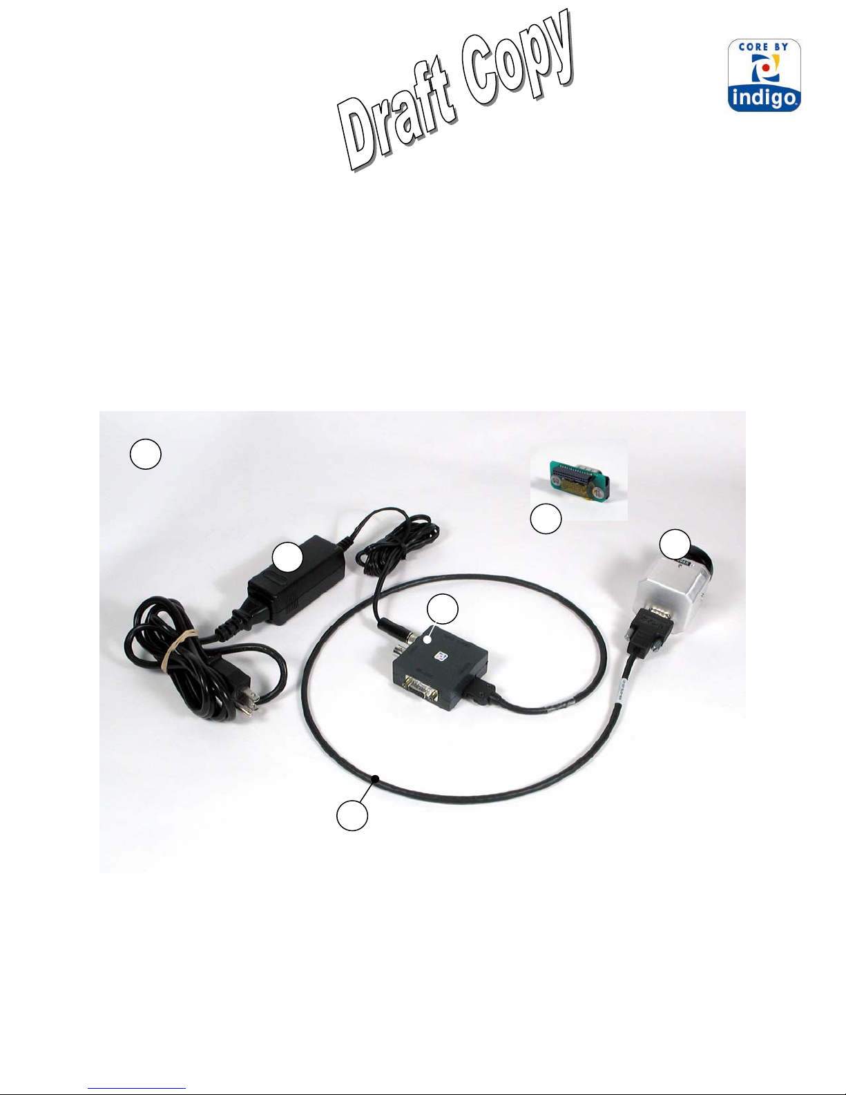
3 UNPACKING YOUR PHOTON CAMERA
The items shown in Figure 2 come standard in your Photon Camera package. If there is any
discrepancy between this list and the contents of your camera package, please contact FLIR
Systems Customer Support immediately at (805) 964-9797.
1. Photon camera
2. I/O Module
3. Interface cable
4. 110/220V AC/DC Converter with outlet plug
5. Wear Saver (may not be needed)
6. User’s Guide and Photon OEM GUI
6
4
5
1
2
3
Figure 2: Standard Photon Camera and OEM Package
5
Page 6

Photon User Guide 412-0035-00-10 Version 100
4 OPTIONAL PHOTON ACCESSORIES
• Digital data serial-to-parallel module (parallel data cable sold separate)
• Pleora IPort
• Battery Pack
Figure 3: Some of the Photon Accessories
5 OVERVIEW OF THE PHOTON ELECTRICAL INTERFACE
Depending on connector type, either a 15-pin HD D-Sub or a 30-pin SAMTEC, thru which
input/output signals are available on the back of the Photon camera.
The 15-pin high density or HD D-Sub connector pin definitions are shown in Table 2. The
signals on this connector include input power, analog video output, serial communication
channel for command and control and the digital data output.
Table 1: 15-Pin HD D-Sub (F) Connector Pin Definitions
Pin # Signal Name Signal Definition
1 VIDEO_HI Analog Video, positive output
2 SD_ FSYNC+ Digital Port 1 Sync, positive output
3 GND Ground
4 GND Ground
5 GND Ground
6 VIDEO_LO Analog Video, negative output see
7 SD_ CLK+ Digital Port 1 Clock, positive output
8 SD_ DATA+ Digital Port 1 Output Data, positive output
9 TX Primary Serial Communication transmit
10 PWR_IN Input voltage
11 SD_CLK- Digital Port 1 Clock, negative output
12 SD_FSYNC- Digital Port 1 Sync, negative output
13 SD_DATA- Digital Port 1 Output Data, negative output
14 RX Primary Serial Communication receive
15 PWR_IN Input voltage
Figure 4: 15-pin HD D-Sub (M) connector on camera
6
Page 7

Photon User Guide 412-0035-00-10 Version 100
The Photon camera provides all input/output signals via a single 30-pin SAMTEC TFML-11502-S-D-P connector (J1) with pin definitions as shown in Table 2 The signals on this connector
include input power, analog video output, serial communication channel for command and
control, external sync, voltage output, I/O pins and the digital data output.
Table 2: 30-pin Power Board to External I/O Connector Pin Definitions
Pin # Signal Name Signal Definition
1,2,5,6 GND Ground
3 3.15V_OUT 3.15V output
4 PWR_IN Input voltage
7 1.5V_OUT 1.5V output
8 LIN Do not connect
9 RX2 Spare Serial Communication receive
10 RX Primary Serial Communication receive
11 TX2 Spare Serial Communication transmit
12 TX Primary Serial Communication transmit
13 LVDS_VID2+ Digital Port 2 Output Data, positive output
14 SD_DATA- Digital Port 1 Output Data, negative output
15 LVDS_VID2- Digital Port 2 Output Data, negative output
16 SD_ DATA+ Digital Port 1 Output Data, positive output
17 LVDS_VID1+ Digital Port 2 Sync, positive output
18 SD_FSYNC- Digital Port 1 Sync, negative output
19 LVDS_VID1- Digital Port 2 Sync, negative output
20 SD_ FSYNC+ Digital Port 1 Sync, positive output
21 LVDS_VID0+ Digital Port 2 Clock, positive output
22 SD_CLK- Digital Port 1 Clock, negative output
23 LVDS_VID0- Digital Port 2 Clock, negative output
24 SD_ CLK+ Digital Port 1 Clock, positive output
25 TEMP2 Temp Sensor port 2
26 DIS0_EXT External Sync
27 DIS2_EXT Discrete Input Channel 2
28 VIDEO_LO Analog Video, negative output
29 DIS1_EXT Discrete Input, Channel 1
30 VIDEO_HI Analog Video, positive output
Note: The mating connector is SAMTEC SFML-115-T1-S-D-K
30
4
29
Figure 5: 30-pin SAMTEC (M) connector on camera
Note: See the Electrical Interface Control Document (ISC doc. 102-1238-41) for detailed interface
requirements. Pin-out definitions for the I/O Module are provided in Appendix A.
7
321
Page 8

Photon User Guide 412-0035-00-10 Version 100
Input Power
Included with the Photon camera is an AC/DC converter that generates 8VDC input power from
110 VAC or 220 VAC. If you prefer to provide your own power supply, please verify that the
input power at the camera connector meets the specifications shown in Table 3 when applied
across PWR_IN and GND pins.
CAUTION: Reversing polarity of input power will damage the camera’s internal power supply
and repair is not covered under the camera warranty.
Table 3: Input Power Requirements
Parameter
Minimum voltage 5.0 V Absolute minimum is 4.8V
Maximum voltage 24.0V Absolute maximum is 26 V
Nominal Load
Power
Peak Load Power
at start-up
Baseline
Value
< 2000 mW Typical power is 1500 mW
4000 mW Assuming no load between
Comment
HTR and HTR_RTN.
Analog Video Output
The video output of the Photon camera can be configured to either NTSC or PAL-compatible.*
In either case, the output is intended to drive a 75-ohm load. Use of coaxial cable with 75 ohm
characteristic impedance is strongly suggested. The analog video signal is across the
VIDEO_LO and VIDEO_HI pins. See Table 4 for a list of other relevant video parameters.
Table 4: Video parameters
Parameter NTSC PAL
Monochrome equivalent RS-170A CCIR
Frame rate 29.97 Hz 25 Hz
Active video lines 480 510
# displayed detector samples 320 (H) x 240 (V) 320 (H) x 255 (V)
Note: To use the Photon Isotherm option, the video monitor must be color capable. For display
of Photon video without Isotherm capability, a monitor complying with the monochromeequivalent standard shown in Table 4 can be used.
*
NTSC is the U.S. standard for color analog video. PAL is the European standard.
8
Page 9

Photon User Guide 412-0035-00-10 Version 100
Command and Control Channel
Remote control of the Photon camera is provided via a RS-232 serial interface consisting of
signals named RX, TX and GND using 3.3 volt signal levels. Section 7 provides information
regarding remote control using the Photon OEM GUI. The Electrical Interface Control
Document (ISC doc. 102-1238-41) describes the serial communications protocol for the Photon
camera.
Digital Data Channel
Photon provides a digital channel with real-time serialized digital video. The camera outputs
either 8-bit or 14-bit data using the SD_CLK±, SD_FSYNC± and SD_DATA± signals.
Conversion of the digital data to a parallel format for data acquisition requires a serial-to-parallel
converter accessory or an Ethernet Module which is also an accessory. Section 8 provides
information regarding the digital data interface. Also, the Electrical Interface Control Document
(ISC doc. 102-1238-41) describes the specific timing information.
External Synchronization
Photon camera provides the ability to either accept or output frame synchronization if needed.
1. Slave Mode: The camera will accept a frame synchronization signal on the interface
connector (DIS0_EXT) when configured as a slave via the serial communications port. The sync
signal starts the FPA frame timing sequence. The sync signal consists of a positive going, 3 volt
pulse as defined in Table 5. The frame sync signal should be sent only once per frame and the
camera core will not output digital data until a valid frame sync is received. The video output
(analog) of the camera core is enabled while in external sync mode, however, the video frame
rate depends upon the external frame sync rate (e.g. the analog video may not conform to timing
standards). The camera synchronization state must be set prior to power-up (e.g. after the mode
is changed and saved, the camera must be re-started).
Table 5: Frame Sync Input Requirements
Frequency
Range
0 to 30 Hz 135ns
Pulse width
(minimum)
2. Master Mode: The camera will output a frame synchronization signal on the interface
connector (DIS0_EXT) when configured as a master via the serial communications port. The
sync signal corresponds to the start of the FPA frame timing sequence. The sync signal shall
consist of a positive going, 3 volt pulse as defined in Error! Reference source not found. . The
frame sync signal shall occur only once per frame. This signal output is intended to drive one
Photon which is configured for slave mode operation.
9
Page 10

Photon User Guide 412-0035-00-10 Version 100
Table 6: Frame Sync Output Requirements
Frequency
Range
29.97 Hz (NTSC
mode)
25 Hz (PAL
mode)
Pulse width
(minimum)
200 ns
200ns
Voltage Outputs
The Photon camera provides two conditioned voltage outputs, 3.15V_OUT and 1.5V_OUT,
intended to power auxiliary electronics and accessories. The characteristics of these two outputs
are shown in Table 7.
Table 7: Output Power Requirements
Parameter 3.15V_OUT 1.5V_OUT
Voltage 3.16V + 0.11V 1.50V + 0.05mV
Max. Supply
Current
500 mA 700 mA
Input/Output Pins
The Photon camera allows for custom defined I/O pins that can be programmed at the factory for
selected applications. Contact FLIR Systems Customer Support at (805) 964-9797 for details.
10
Page 11

Photon User Guide 412-0035-00-10 Version 100
6 BASIC OPERATION OF THE PHOTON CAMERA
Note: If you are using the Ethernet Module or SIPO adapter additional instructions may also be
provided.
1. Remove the lens cap. (Remember to replace the lens cap when the camera is not in use
to prevent accidental scratching and dust contamination.)
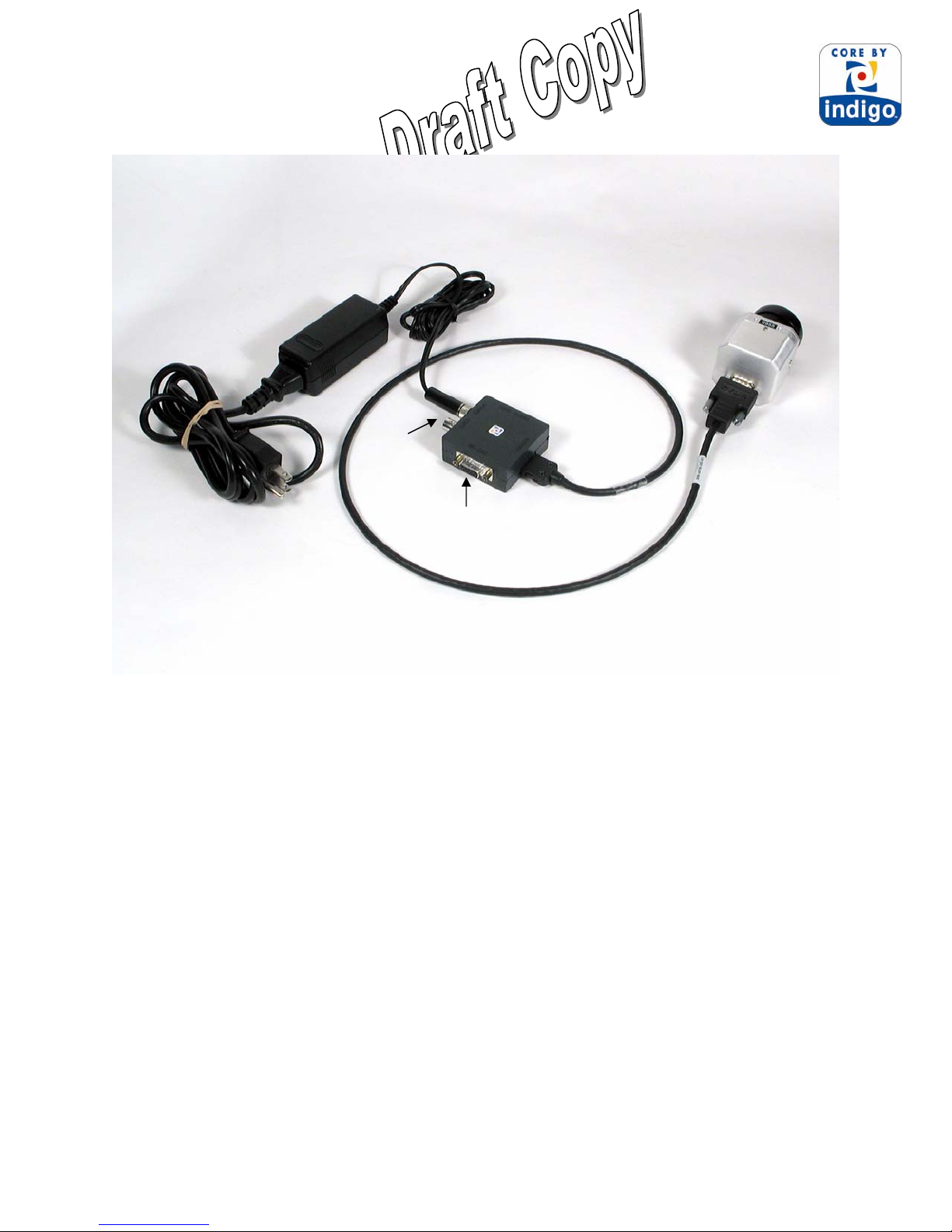
2. If using the standard Interface Cable and I/O Module, plug one end of the Interface Cable
into the mating connector on the back of the camera, as shown in Figure 6 . (Either end
of the Interface Cable can be plugged into the camera.) Connect the other end of the
Interface Cable to the mating connector on the I/O Module labeled “CAMERA”.
3. Attach one end of a standard BNC cable to the video port labeled “VIDEO” on the I/O
Module. Attach the other end to a compatible video monitor.
4. Attach one end of a standard RS-232 serial port (9-pin) PC cable to the communications
port labeled “RS-232” on the I/O Module. Attach other end to the serial port on the PC.
5. Plug the AC/DC converter into an electrical outlet. Insert the circular plug at the other
end of the AC/DC converter into the power jack labeled “POWER” on the I/O Module.
The camera will take ~1 second to produce an image after application of power.
6. The camera will automatically perform a flat-field correction (FFC) at periodic intervals.
This operation, which improves image quality, takes less than 1/2 second to complete.
This feature can be disabled or controlled manually or with a time delay via the Photon
OEM GUI (See page 16 .)
7. If you intend to use the Photon OEM GUI for remote control of the camera, follow the
additional steps described in Section 7. Figure 6 shows the I/O Module and camera after
cabling power, analog video and RS-232 interface.
8. If you intend to use the digital data channel, follow the additional steps described in
Section 8.
11
Page 12
Photon User Guide 412-0035-00-10 Version 100
To video
monitor
To electrical outlet
(only required if using RS-232
To PC
interface.)
Figure 6: Photon after cabling
7 REMOTE CONTROL OF THE PHOTON CAMERA
The Photon provides advanced camera control through an RS-232 serial interface. This can be
accessed using a PC with the standard serial communications port and the I/O Module. Included
with your Photon is PC-based Control Panel software that communicates with the camera. This
software provides remote control of various camera features and modes as well as image capture
using a graphical user interface (GUI). The Photon OEM GUI software is compatible with
Windows 2000 / 2000 Professional, and Windows XP Professional. The PC must have a spare
serial communications port for the I/O Module the Control Panel software.
If your application demands for embedded or specialty applications that require custom control
software, a Software Developer’s Kit (SDK) and an Electronic Interface Control Document
(ICD) are available to support your development efforts. Those intending to generate their own
custom software are encouraged to read the remainder of this section regarding the Photon OEM
GUI to better understand the camera modes and parameters.
12
Page 13

Photon User Guide 412-0035-00-10 Version 100
Installation of Photon Control Panel Software
1. Insert the CD marked Photon OEM GUI into your CD-ROM drive. If the setup program
(setup.exe) does not execute automatically, then execute it by finding setup.exe in the
CD-ROM with Windows Explorer and double-clicking the icon. (Alternatively, you can
select “Run” from your Windows start menu, and then type “E:\ setup.exe”, replacing E:
with the appropriate drive-letter for your CD-ROM.)
2. The installation program will present instructions for installing the application to your
hard drive. By default, the setup wizard will install the application in the directory
C:\ProgramFiles\Indigo\Photon, and the filename is OEMGUI.exe.
Connecting Photon to a PC via the I/O Module
1. Follow the steps shown in Section 6 for basic operation of the Photon camera. After
verifying that the camera is producing an image, power down the camera.
2. Connect one end of a standard serial cable (not included) to the 9-pin female DB9
connector on the I/O module labeled “RS-232”.
3. Connect the other end of the standard serial cable to an unused serial port on your
computer. These ports are usually labeled “COM1”, “COM2”, etc.
4. Power on the camera. Assuming the Control Panel software is already installed on the
PC (see installation instructions above), execute the software.
5. The Control Panel software will attempt to automatically identify the COM port upon
which the camera is installed. If the Control Panel successfully links to the camera, skip
ahead to the section below titled “Operation of the Photon Control Panel”.
Troubleshooting the Command & Control Link
If the Control Panel software does not link with the camera, verify the items in the following
checklist:
1. Is the camera properly cabled to the host PC? Verify that you selected the proper port if
it was not detected automatically. Also, try un-connecting and then re-connecting either
the RS-232 serial cable to the PC .
2. Is the port already in use by another application? Shut down any other applications that
may be using the port. Also, multiple instances of the Photon Camera Control Program
can be instantiated using different ports.
3. Is the Photon camera power on? Verify that the camera is producing an image on a
separate monitor.
Contact Indigo Customer Support at (805) 964-9797 if you cannot initiate serial communication
with the camera after verifying these items.
13
Page 14
Photon User Guide 412-0035-00-10 Version 100
Operation of the Photon Control Panel
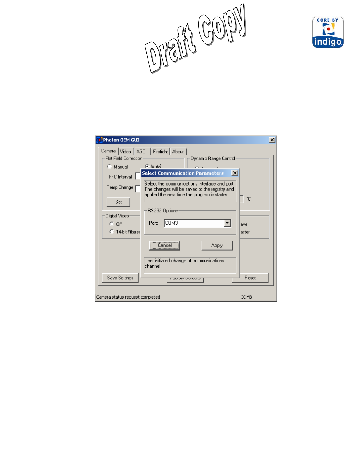
When the Control Panel successfully links to the camera, you may see the communications
window shown in Figure 7 then select the correct comm. Port and hit apply. The Control Panel
provides five tabs allowing for camera control as well as the ability to save/load configuration
settings and custom splash screens. It also provides a text message across the bottom showing
status information reported back from the camera after each command.
Figure 7: Photon Control Panel, Communication Tab
14
Page 15

Photon User Guide 412-0035-00-10 Version 100
7.1.1 Control Panel Camera Tab
The Camera Tab on the Control Panel, shown in Figure 8, provides the ability to modify the Flat
Field mode, the Digital Output mode as well as select the Dynamic Range and External Sync
modes.
Figure 8: Photon Control Panel, Camera Tab
Flat-Field-Correction Mode: Photon includes internal mechanisms for periodically
improving image quality via a process called “flat-field correction” (FFC). During FFC, a
small calibration flag rotates in front of the detector array, presenting a uniform temperature
(i.e. a “flat field”) to every detector element. While imaging the flat-field, the camera
updates correction coefficients, resulting in a more uniform array output. The video image is
frozen during the entire process, which takes approximately half a second, and it resumes
automatically thereafter. Repeating the FFC operation often prevents the imagery from
appearing “grainy”. This is especially important when camera temperature is fluctuating,
such as immediately after turn-on and/or when ambient temperature is drifting. FFC can be
commanded manually at any time using the FFC command in the Control Panel menu bar.
Photon provides two FFC modes for configuring automatic FFC conditions:
15
Page 16

Photon User Guide 412-0035-00-10 Version 100
1. Automatic. In the Automatic FFC mode, the camera performs FFC whenever its
temperature changes by a specified amount or at the end of a specified period of time
(whichever comes first). When this mode is selected, input windows are available on the
Control Panel for specifying the temperature change and the number of frames that
trigger automatic FFC. The temperature change is specified in degrees, with valid values
in the range 0 to 100 in 0.1 degree increments. The time period is specified in frames,
with valid values in the range 0 to 30,000 frames.
Note: It is recommended to use the factory default values for the two automatic-FFC
parameters if possible. These values were selected to maintain a high degree of image
quality over all camera operating conditions.
2. Manual
. In Manual FFC mode, the camera does not perform FFC automatically based on
specified values of temperature change or expired time.
Note: Even in manual FFC mode, Photon will perform automatic FFC when it changes
between low-temperature and high-temperature states. Furthermore, as the camera is
heated or cooled during operation, it will perform FFC automatically when its temperature
crosses through the different Non-Uniformity Correction tables.
On-Screen-Symbol: Photon uses on-screen symbols for displaying important camera status.
Specifically, the following indicator is provided:
a. FFC Imminent
: displayed nominally 2 seconds before automatic FFC.
Figure 9 shows the approximate size and location of this indicator on the display.
Figure 9: Approximate size and location of FFC-imminent indicator
Digital Output Modes: The Photon provides a digital data channel with four selectable
modes:
16
Page 17

Photon User Guide 412-0035-00-10 Version 100
1. Off. The digital data stream coming from the Photon camera is turned off.
2. 8-bit data. Data from the 320x240 (NTSC) or 320x255 video pixels (PAL) is provided
after application of the current AGC or Image-Optimization mode (refer to Section
7.1.2), isotherms, and on-screen symbols. The 8-bit data is essentially a digital version
of the same data provided on the analog video channel.
3. 14-bit data Filtered. Data from 324x256 pixels is provided prior to the video processing
modes in the 8-bit data described above. The 14-bit data is the *filtered* data to include
the Dynamic Detail Enhancement (DDE) and will appear gray when saving 16-bit TIFF
files.
4. 14-bit data Raw. Data from 324x256 pixels is provided prior to all video processing and
does not include the Dynamic Detail Enhancement. The 14-bit data is the *raw* data and
will also appear gray when saving 16-bit TIFF files.
Note: Only in the 8-bit mode will selecting AGC mode affect the digital data output.
Dynamic-Range Control Mode: Photon provides a low-temperature (high-sensitivity) state
intended for imaging scenes that are nominally less than 150 oC (302 oF) as well as a hightemperature (low-sensitivity) state intended for imaging up to 500 oC (932 oF). Three
Dynamic-Range-Control modes are provided for selecting the gain-state:
1. Automatic. In the optional Automatic mode, the camera automatically selects the
optimum state, low-temperature or high-temperature, based on scene content.
2. Low-Sensitivity. The camera operates exclusively in the high scene temperature (lowsensitivity) state.
3. High-Sensitivity. The camera operates exclusively in the low scene temperature (highsensitivity) state.
The current NUC table shows the active Non-Uniformity Correction table the camera is
using. The NUC table will automatically be selected when in Automatic mode.
Note: If your camera does not include the optional automatic dynamic-range-control feature,
you will not have the option of selecting this mode via the Control Panel. You will have the
ability to manually select Low Temp. or High Temp. modes.
FPA Temperature. The FPA Camera Temperature updates the automatically with a
measurement of camera FPA temperature. This temperature is measured on the camera’s
FPA or Focal Plane Array.
External Sync Mode: The Photon camera provides the ability to either accept or output
frame synchronization if needed. This functionality can also be disabled.
17
Page 18

Photon User Guide 412-0035-00-10 Version 100
1. Disabled Mode: The camera will turn off frame synchronization.
2. Slave Mode: The camera will accept a frame synchronization signal on the interface
connector.
3. Master Mode: The camera will output a frame synchronization signal on the interface
connector when configured as a master.
Note: See the Electrical Interface Control Document (ISC doc. 102-1238-41) for detailed
External Sync requirements.
Save Settings. After using the Control Panel to change all camera modes and settings to
desired values, use the Save Settings command to store your current selections as power-up
defaults. The next time the camera is powered, it will revert to the settings saved as defaults.
Factory Defaults. The Factory Defaults command restores the camera’s modes and settings
to the initial values originally specified by the manufacturer, replacing the customized
selections stored used in the Save Settings command.
Reset. The Reset command causes the camera to revert to its power-up default settings just
as if input power was toggled.
18
Page 19

Photon User Guide 412-0035-00-10 Version 100
7.1.2 Control Panel Video Tab
The Video Tab on the Control Panel, shown in Figure 10, provides the ability to modify six
different Photon modes: Image Orientation mode, Pan & Zoom, Polarity/LUT, Dynamic Detail
Enhancement, Video Standard mode and Test-Pattern mode.
Figure 10: Photon Control Panel, Video Tab
Image-Orientation Mode: Four Image-Orientation modes are provided:
1. Normal. The pixel on the upper-right corner of the detector array is displayed on the
upper-left corner of the video display in Normal mode.
2. Invert
. The pixel on the upper-left corner of the detector array is displayed on the upper-
left corner of the video display in Revert mode.
3. Revert. The pixel on the upper-left corner of the detector array is displayed on the upperleft corner of the video display in Revert mode.
4. Both
. The Invert and Revert display have been applied to the displayed data.
Notes: Revert mode (i.e. horizontal image flip) produces a mirror-image of Normal mode. It
is intended for applications in which the camera is imaged through a fold-mirror. Invert (i.e.
vertical image flip) can be accomplished by mounting the camera upside-down.
19
Page 20

Photon User Guide 412-0035-00-10 Version 100
Pan & Zoom: The Pan & Zoom also called PAN_AND_TILT command controls the camera
when the image is zoomed. It does not have any effect when the image is not zoomed. The
center of the screen is considered as coordinate (0,0). A positive number is needed to pan
right and negative number to pan left. A pan value of 1 pans to the right by one column and a
pan value of -1 pans to the left by one column from the center of the image. A positive
number is needed to tilt downwards and a negative number to tilt upwards. A tilt value of 1
tilts downwards by one row and a tilt value of -1 tilts upwards by one row from the center of
the image. When the image is being panned or tilted the ROI moves along with these
coordinates. The limits for the zoom ROI have been set to one and a half times the number of
rows and columns in the video. This is to enable a user to pan and tilt the zoomed portion of
the image without any change in the AGC if the image being looked at does not change. This
also means that the AGC of the image is also determined by portions of the image that is not
being currently viewed. An example of this is as shown in the Figure 11.
When the image is panned right to the maximum limit as shown in Figure 12, the number of
pixels in the ROI remains constant and the AGC of the image will not change.
Figure 11: ROI format
20
Page 21

Photon User Guide 412-0035-00-10 Version 100
ROI
VIDEO
Figure 12: Maximum ROI
If the ROI is set to the size of the visible portion of the zoomed image as shown in Figure 13 and
the image is tilted to the maximum limits as shown in Figure 14, pixels will not be dropped from
the ROI but the AGC will change as the ROI changes with the pan and tilt coordinates. The AGC
is determined only by the visible portion of the image.
Figure 13: ROI centered in video
If the ROI is set to larger than the visible portion of the zoomed image and smaller than one and
a half times the number of columns and rows as shown in Figure 15 and if the image is tilted to
the maximum limit, pixels are dropped from the ROI as shown in the Figure 16.
Figure 14: ROI at maximum tilt
21
Page 22

Photon User Guide 412-0035-00-10 Version 100
Figure 15: ROI larger than Zoomed video
Figure 16: ROI clipped
Note: Selecting the Pan & Zoom mode will not affect the digital data output.
Polarity/LUT: Imagery can be displayed in a variety of LUTs or Look Up Tables. The most
common selection is either white-hot (hotter objects brighter than cooler objects) or blackhot polarity (hotter objects darker than cooler objects). Table 8 shows each of the LUTs in a
ramp pattern starting with the upper left: White Hot, Black Hot, Fusion, Rainbow, Globow,
Ironbow1, Ironbow2, Sepia, Color1, Color2, Ice Fire and Rain. Select from the pull-down
menu and save settings once desired palette is selected.
Table 8: Photon LUTs
Note: Selecting Polarity/LUT mode will not affect the digital data output.
22
Page 23

Photon User Guide 412-0035-00-10 Version 100
Dynamic Detail Enhancement or DDE filter: This option applies a Bi-Lateral filter to
enhance image. The commands to control the DDE settings are Filter Gain to control the
gain, Filter Control to control the DDE filter threshold and Spatial Control to control the
spatial threshold of the DDE filter.
1. Filter Gain. The image remains unchanged when the value of the Filter Gain is 0 and 16.
The image becomes unfocussed/unsharpened when the value is between 1 and 15. The
image becomes more sharpened when the value is above 16. The Filter Gain can be set
between 0 and 250.
2. Filter Control
. Increasing the Filter Control, also called the threshold, will make the
edges sharper. For threshold values between 0 and about 50 the effect on the image is
lesser and has a greater effect above approximately 50. The Filter Control can be set
between 0 and 250.
3. Spatial Control
. Increasing the spatial threshold value will make the image look
smoother. The Spatial Control can be set between 0 and 255.
Note: In 14-bit Raw mode, selecting the DDE mode will not affect the digital data output.
Video Mode: Three Video modes are provided for configuring the camera output:
1. Real-Time. In this mode, the camera provides streaming thermal imagery in real-time.
2. Freeze-Frame. The camera freezes the image at the moment this mode is selected,
providing the same frame continuously.
3. Disabled. Infrared imagery is replaced by a uniform gray output in this mode.
Video Standard: Two Video modes are provided for configuring the camera video output:
1. NTSC
2. PAL
. The RS-170A or NTSC is a standard video format used in the United States.
. The CCIR or PAL is a standard video format used commonly in Europe.
23
Page 24

Photon User Guide 412-0035-00-10 Version 100
Test-Pattern Mode: A Test-Pattern mode is provided to verify camera electronics.
1. Off
. No test-pattern is provided in this mode. This is the normal mode for viewing
thermal imagery.
2. Ramp
. In this ramp mode, the test pattern shown in Figure 17 is provided at the analog
and digital data channels.
pix(0,0) = 0
pix(323,0) = 323
pix(183,50) = 16383
pix(184,50) = 0
Figure 17: Ramp test pattern
(Digital values shown apply to the optional 14-bit digital data stream.)
Note: The ramp test pattern is intended primarily for verifying the output of the digital data
channel. The pattern will not necessarily look as shown in Figure 17 when displayed on an
analog video monitor, particularly if an AGC mode other than Automatic is selected.
24
Page 25

Photon User Guide 412-0035-00-10 Version 100
7.1.3 Control Panel AGC Tab
The AGC Tab on the Control Panel, shown in Figure 18, provides the ability to modify three
different camera modes: AGC or Automatic Gain Control mode, AGC Parameters, Linear
Parameters and Region Of Interest or ROI.
Figure 18: Photon Control Panel, AGC Tab
AGC Mode: The Photon provides five AGC or Image-Optimization modes:
1. Automatic
. In Automatic mode, image contrast and brightness are optimized
automatically as the scene varies. This mode provides an Automatic Gain Control
(AGC) which is based on a histogram-equalization (HEQ) algorithm. The AGC
Parameters below allow for the Plateau, grey scale mid-point (ITT Mean) and Max Gain
terms of the Automatic to be manipulated based at the user’s need. The input windows
for specifying contrast, brightness, and brightness bias are grayed out on the Control
Panel when Automatic is enabled since they are not used in this mode.
25
Page 26

Photon User Guide 412-0035-00-10 Version 100
2. Auto-Bright. In Auto-Bright mode, image brightness is optimized automatically as the
scene varies but contrast is manually specified. Generally, Automatic AGC produces a
better image than Auto-Bright, but in some cases, specifying contrast manually can
improve the display of a specific feature in a scene. When Auto-Bright mode is selected,
input windows for specifying contrast and brightness-bias values are available on the
Control Panel. To specify a value, type it directly into the appropriate input window or
use the up/down arrow keys. Valid contrast values range from 0 to 255, with a smaller
value producing less contrast and a larger value producing more. The brightness bias
value ranges from –16383 to +16383. When brightness bias is 0, the camera applies the
value of brightness determined to be optimal for the current scene conditions.
Increasingly negative values cause a darker image than optimal whereas increasingly
positive values cause a brighter image.
3. Once Bright
. In Once Bright mode, image brightness and contrast are both specified
manually, which can occasionally improve the display of specific features in a scene,
particularly those that are significantly hotter or colder than the average scene
temperature. Upon entry into the Once Bright mode, Photon automatically optimizes the
value of brightness just as in Auto-Bright mode. However, the brightness value is not
continuously updated as the scene varies or as camera temperature changes. Valid
brightness values range from 0 to 16383, with a smaller value producing a darker image
and a larger value producing a brighter imager. Brightness bias is not used in this mode.
4. Manual
. Image brightness and contrast are both manually specified in Manual mode.
Unlike the Once Bright mode described above, the brightness value is not automatically
optimized upon entry into the Manual mode. Instead the last specified values for both
brightness and contrast are applied. (The power-on defaults are applied if brightness
and/or contrast have not already been specified using the Control Panel.) Brightness bias
is not used in this mode.
5. Linear Histogram. Image contrast and brightness (gain and level) are optimized
automatically based upon scene statistics using a linear transfer function. Controls for the
gray scale mid-point (ITT mean) and maximum gain (AGC gain) are adjustable using the
serial commands. The region of interest (ROI) for the histogram is adjustable using a
serial command. The corner locations (upper right and lower left) with respect to the
center of the image shall be used to determine the ROI location. Upon entry into the
linear histogram mode, the currently-stored values are applied (i.e. the power-on defaults
or the last saved values).
6. Logarithmic
. Image contrast and brightness (gain and level) optimized automatically
based upon scene statistics using a logarithmic transfer function. Controls for the gray
scale mid-point (ITT mean) and maximum gain (AGC gain) shall be adjustable using the
serial commands. The region of interest (ROI) for the histogram shall be adjustable using
a serial command. The corner locations (upper right and lower left) with respect to the
center of the image shall be used to determine the ROI location. Upon entry into the
linear histogram mode, the currently-stored values are applied (i.e. the power-on defaults
or the last saved values)
26
Page 27

Photon User Guide 412-0035-00-10 Version 100
Note: In Manual mode and Once Bright mode, the brightness setting must be updated as the
camera temperature changes. To avoid this issue, it is recommended to use Automatic or AutoBright modes when possible. Also, only in the 8-bit mode will selecting AGC mode affect the
digital data output.
Linear Parameters: The Linear Parameters are used for fine tuning the Auto Bright, Once
Bright and Manual modes. Each of their settings is described accordingly in detail above.
AGC Parameters: The AGC Parameters are used tuning the Automatic, Linear Histogram and
Logarithmic modes. Each of their setting is described accordingly in detail above.
Region Of Interest: The Photon camera allows the user to select the Region Of Interest that
which the AGC will use for it’s calculations. This Region Of Interest or ROI can be set for
either the entire frame size or some other portion as shown below in Figure 19. The settings are
similar to an X-Y coordinate system with 0,0 in the middle. Refer to the section for Pan & Zoom
on Page 4 for detail information on how these features work together.
Figure 19: Photon ROI defined
27
Page 28

Photon User Guide 412-0035-00-10 Version 100
7.1.4 Control Panel About Tab
The About Tab on the Control Panel, shown in Figure 20, provides information on the Photon
camera along with the ability to load splash screen and camera configuration.
Figure 20: Photon Control Panel, About Tab
Load Splash Screen. The Load Splash Screen option allows users to load a custom splash
screen to the Photon camera for use during startup. The file must be of size 324x256 (approx
83 KB) and a BMP format.
Camera Configuration. The Camera Configuration allows users to load a standard
configuration file (power on defaults) as well as load field upgrades.
Comm. Test. The Comm. Test command is a diagnostic feature for verifying the
communication link between the Control Panel and the Photon camera. Use this command if
you suspect that the camera and Control Panel are not communicating properly. The
message box in the lower left corner of the Control Panel will state “Communication test
completed” if the interface is working properly. If the message box reports “Camera
Timeout”, the link between the camera and Control Panel has been disrupted. Verify that the
camera is still powered and that the serial cable to the PC has not been disconnected. If you
cannot re-establish the Control Panel link, call FLIR Customer Support at (805) 964-9797 for
assistance.
28
Page 29

Photon User Guide 412-0035-00-10 Version 100
8 PHOTON DIGITAL DATA CHANNEL
Photon provides a digital data channel that provides thermal imagery in digital format. This
channel can be used in conjunction with commercially-available digital frame grabbers, digital
displays, or custom receive electronics. Again, for Photon users with embedded or specialty
applications that require custom control software, a Software Developer’s Kit (SDK) and an
Interface Control Document (ICD) are available to support your development efforts.
The digital data channel can be configured to output 14-bit data after application of calibration
terms. This mode is most useful for external signal-processing and/or analysis of the camera
output. The digital channel can also be configured to provide 8-bit data after application of
video processing algorithms (e.g. “automatic”, white-hot/black-hot polarity, image orientation,
DDE filtered, and on-screen symbols). The 8-bit data is essentially a digital version of the video
stream provided on the analog video channel and is therefore more appropriate than the 14-bit
data for interfacing to a digital display.
The digital data channel employs serial low-voltage differential signaling (LVDS). The channel
consists of three signal lines – a clock, a composite sync (frame sync and line sync), and serial
data. A serial-in-parallel-out (SIPO) module is available from FLIR Systems for converting the
serial data to 14-bit parallel LVDS output (plus frame sync, line sync, and pixel clock). The
parallel data can be captured using a frame-grabber board installed in a PC. Two commercial
frame grabbers are currently supported: Bitflow Road Runner PCI 12 and National Instruments
PCI-1422. Cabling and software configuration files for either frame grabber are available from
Indigo Systems.
Indigo also offers an optional digital data converters such as the Ethernet Module. The Ethernet
Module connects the Photon digital output directly to a LAN using standard CAT-5 LAN cable.
Using either the Ethernet Module allows for digital output and camera control via the Photon
SDK software directly to a PC.
For users intending to interface directly to the camera’s serial digital data channel, detailed
timing and format information is provided in the ICD (ISC doc. 102.1238.41). Information on
the timing and data format of the parallel output is also provided in separate ICD specific to the
SIPO module (ISC doc. 333.0008.19). Please contact FLIR Systems Customer Support to
request either of these documents.
Using the Digital Data Channel
Note: The following instructions assume that you have purchased the optional serial-to-parallelout (SIPO) accessory module with parallel data cable. If you are using the Ethernet module,
29
Page 30

Photon User Guide 412-0035-00-10 Version 100
follow the instructions with the device. If you are using custom cabling and/or interface
electronics, contact FLIR Systems Customer Support at (805) 964-9797 if you need additional
assistance.
1. Follow the steps shown in Section 6 for basic operation of the Photon camera. After
verifying that the camera is operating properly, disconnect power from the Interface
Module.
2. Connect the SIPO accessory module directly to the three-row DB15 connector on the
Interface Module labeled “DIGITAL DATA”. (No cabling is required.)
3. Connect the parallel data cable to the mating connector on the SIPO module. Connect
the other end to the frame-grabber board installed in your PC.
Note: The parallel data cable is specific to a particular frame grabber. In other words, a
parallel data cable intended to mate to a Bitflow frame grabber will not mate with a
National Instruments frame grabber or vice versa.
4. Follow instructions included with the frame grabber for selecting the camera
configuration file included with the SIPO module.
5. Reapply power to the Interface Module. This will power-up both the Photon camera and
the SIPO module, and digital data will begin streaming.
6. If desired, change the digital data mode using the Control Panel software (see Section
7.1.1).
9 PHOTON PHYSICAL INTERFACE
Dimensioned Drawings
A dimensional drawing for each lens configuration is shown in Table 9 . The Table 9 also shows
a list of corresponding ICDs or Interface Control Documents of the Photon camera in the 14.25
mm, 19 mm, 30 mm, 35 mm and 50 mm lens configurations, respectively.
Table 9: Photon Lens Configurations
Figure Number Nominal focal length ICD
Figure 21 14.25 mm 102-1239-78
Figure 22 19 mm
Figure 23 30 mm
Figure 24 35 mm
Figure 25 50 mm
102-1239-77
102-1239-78
102-1239-80
102-1239-83
Weight
Below in Table 10 are the combined weight of the Photon Camera core and the lens.
30
Page 31

Photon User Guide 412-0035-00-10 Version 100
Table 10: Photon Camera Core and Lens Combined Weight
Photon camera focal
length
14.25 mm
19 mm
30 mm
35 mm
50 mm
Weight
Mounting
There is a single threaded mounting hole on the bottom surface of the camera. For precision
alignment, there is also a hole on the bottom surface that allows an anti-clocking pin to be
installed in the mounting platform.
31
Page 32

Photon User Guide 412-0035-00-10 Version 100
32
Figure 21: Photon 14-mm lens configuration
Page 33

Photon User Guide 412-0035-00-10 Version 100
33
Figure 22: Photon 19-mm lens configuration
Page 34

Photon User Guide 412-0035-00-10 Version 100
34
Figure 23: Photon 30-mm lens configuration
Page 35

Photon User Guide 412-0035-00-10 Version 100
35
Figure 24: Photon 35-mm lens configuration
Page 36

Photon User Guide 412-0035-00-10 Version 100
36
Figure 25: Photon 50-mm lens configuration
Page 37

Photon User Guide 412-0035-00-10 Version 100
APPENDIX A: PIN-OUT DEFINITIONS
I/O Module
Camera Connector: Same as camera connector. See Table 1for valid mates.
Power Connector
Video Connector
Serial Connector
Digital Data Connector
: Mates to Switchcraft S760 Miniature Power Plug.
: Mates to 75Ω BNC twist-on plug.
: Mates to DB9 Male.
: Mates to Three-Row DB15 Female.
Table A1: I/O Module Power Connector Pin-Out
Pin # Signal Name Signal Definition
Pin PWR input power
Sleeve PWR_RTN input power return
Table A2: I/O Module Video Connector Pin-Out
Pin # Signal Name Signal Definition
Pin VIDEO analog video output
Sleeve VIDEO_RTN analog video return
Table A3: I/O Module Serial Connector Pin-Out
Pin # Signal Name Signal Definition
2 RX_232 RS232 Receive channel
3 TX_232 RS232 Transmit channel
5 DGND Digital Ground
1,4, 6-9 NC Spare (do not connect)
37
Page 38

Photon User Guide 412-0035-00-10 Version 100
Table A4: I/O Module Digital Data Connector Pin-Out
Pin # Signal Name Signal Definition
1 DATA_SYNC+ Digital data sync (LVDS high)
2 DATA_OUT+ Digital data output channel (LVDS high)
4 DATA_CLK+ Digital output channel clock (LVDS high)
6 DATA_SYNC- Digital data sync (LVDS low)
7 DATA_OUT- Digital data output channel (LVDS low)
9 DATA_CLK- Digital output channel clock (LVDS low)
10 DGND Digital ground
11 PWR input power (connected to power connector pin)
12 PWR_RTN input power return (connected to power connector
sleeve)
13 NC Spare (do not connect)
3,5,8,14,15 NC Spare (do not connect)
38
 Loading...