

Page 1
MARINER
Operator’s Manual
Document # 427-0010-00-10
Version 120, October 2006
Mariner Operator’s Manual
Page 2

© FLIR Inc., 2006. All rights reserved worldwide. No parts of this manual,
in whole or in part, may be copied, photocopied, translated, or transmitted
to any electronic medium or machine readable form without the prior
written permission of FLIR Inc.
Names and marks appearing on the products herein are either registered
trademarks or trademarks of FLIR Inc. and/or its subsidiaries. All other
trademarks, trade names, or company names referenced herein are used
for identification only and are the property of their respective owners.
This product is protected by patents, design patents, patents pending, or
design patents pending.
FLIR Inc.
Indigo Operations
70 Castilian Drive
Goleta, CA 93117
Phone: 1-888-747-FLIR
www.flir.com
www.corebyindigo.com
Page 3
Warnings and Cautions
1
Introduction
Getting Started
Caring for your new ThermoVision® Mariner
Options and Accessories
2
3
4
5
Technical Data
Mounting Templates
Infrared Technology
427-0010-00-10, version 120 11/06 iii
6
7
8
Page 4
Page 5

Mariner Operator’s Manual
Table of Contents
1 Warnings and Cautions
2 Introduction
3 Getting Started
3.1 Parts List ................................................................................5
3.2 Operational Overview ...............................................................6
3.3 Installation .............................................................................8
3.3.1 Camera Mounting ...........................................................8
3.3.2 Joystick Control Unit (JCU) Mounting ...............................9
3.4 Using your new ThermoVision
®
Mariner ...................................11
4 Caring for your new ThermoVision
4.1 Troubleshooting .....................................................................15
4.2 Replacing the fuses ...............................................................16
4.2.1 Cleaning ......................................................................17
5 Options and Accessories
5.1 Mariner Dual Control Station Accessory Kit ..............................19
5.2 Dual Control Selector Mounting ..............................................20
5.3 Optional Extension Cables ......................................................22
6 Technical Data
6.1 Performance Specification ......................................................23
7 Mounting Templates
7.1 Camera Mounting Template. ...................................................25
7.2 Joystick Mounting Template ...................................................27
9 Infrared Technology
9.1 History of Infrared ................................................................29
9.2 How do Infrared Cameras Work? ..............................................34
®
Mariner
427-0010-00-10, version 120 11/06 v
Page 6

Page 7
1 Warnings and Cautions
This guide uses the term Caution to indicate a potentially hazardous
situation, which, if not avoided, may result in minor injury, damage to the
Mariner, or other property damage.
Caution! Failure to follow, may result in damage to the equipment.
1
427-0010-00-10, version 120 11/06 1
Page 8
1 – Warnings and Cautions
Mariner Warnings and Cautions:
For best results and user safety, the following warnings and cautions
should always be followed when handling and operating your camera.
Caution!
The ThermoVision
intended to be used as the primary navigation system.
It should be used in conjunction with other navigation
aids and a primary manual navigation system.
®
Mariner imaging system is not
Do not open the camera body for any reason.
Disassembly of the camera (including removal of the
cover) can cause permanent damage and will void the
warranty.
Great care should be exercised with your camera
optics. They are delicate and can be damaged with
improper cleaning. Refer to paragraph 4.2.1
“Cleaning” on page 17.
Operating the camera outside of the specified input
voltage range or the specified operating temperature
range can cause permanent damage.
Do not image extremely high intensity radiation
sources, such as the sun, lasers, arc welders, etc.
The camera is a precision optical instrument and
should not be exposed to excessive shock and/or
vibration. Refer to Chapter 6 “Technical Data” on page
23 for detailed environmental requirements.
2 11/06 427-0010-00-10, version 120
Page 9

2 Introduction
Congratulations!
You have purchased one of the most sophisticated and important
instruments that you will have on your vessel. The FLIR ThermoVision
Mariner is a state-of-the-art thermal imaging system that will provide you
with excellent night visibility and situational awareness without any form
of natural or artificial illumination.
The ThermoVision® Mariner system is designed for simple, intuitive
operation. The basic system includes a pan and tilt camera assembly and
a remote joystick for steering the camera. It uses standard 12V battery
power and provides a composite video output compatible with standard
display systems. Imagery from the camera can be displayed on a variety of
video monitors, including most multi-function plotter/displays (MFDs)
used with electronic navigation charts. The output is NTSC or PAL, the
same format used on standard televisions and VCRs. It features a wide
field of view and is capable of providing an image even in absolute
darkness.
®
2
427-0010-00-10, version 120 11/06 3
Page 10
2 – Introduction
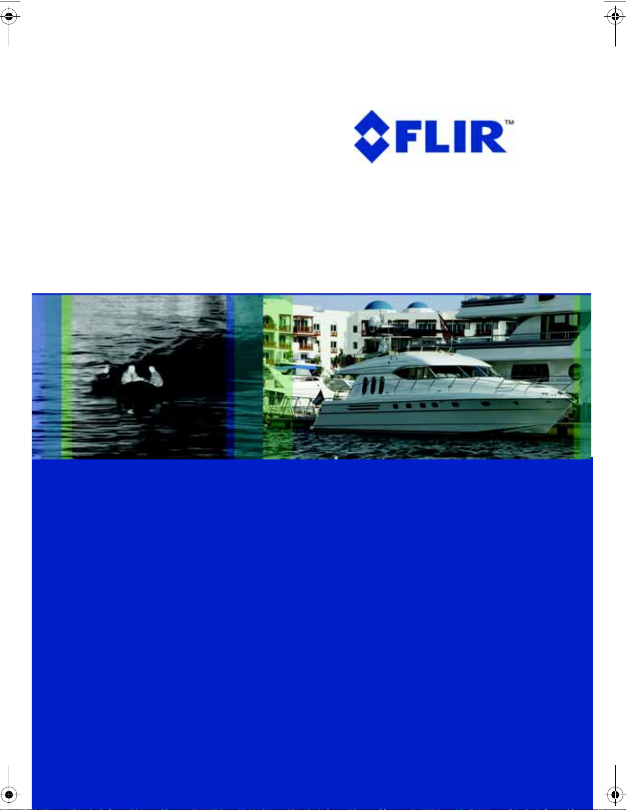
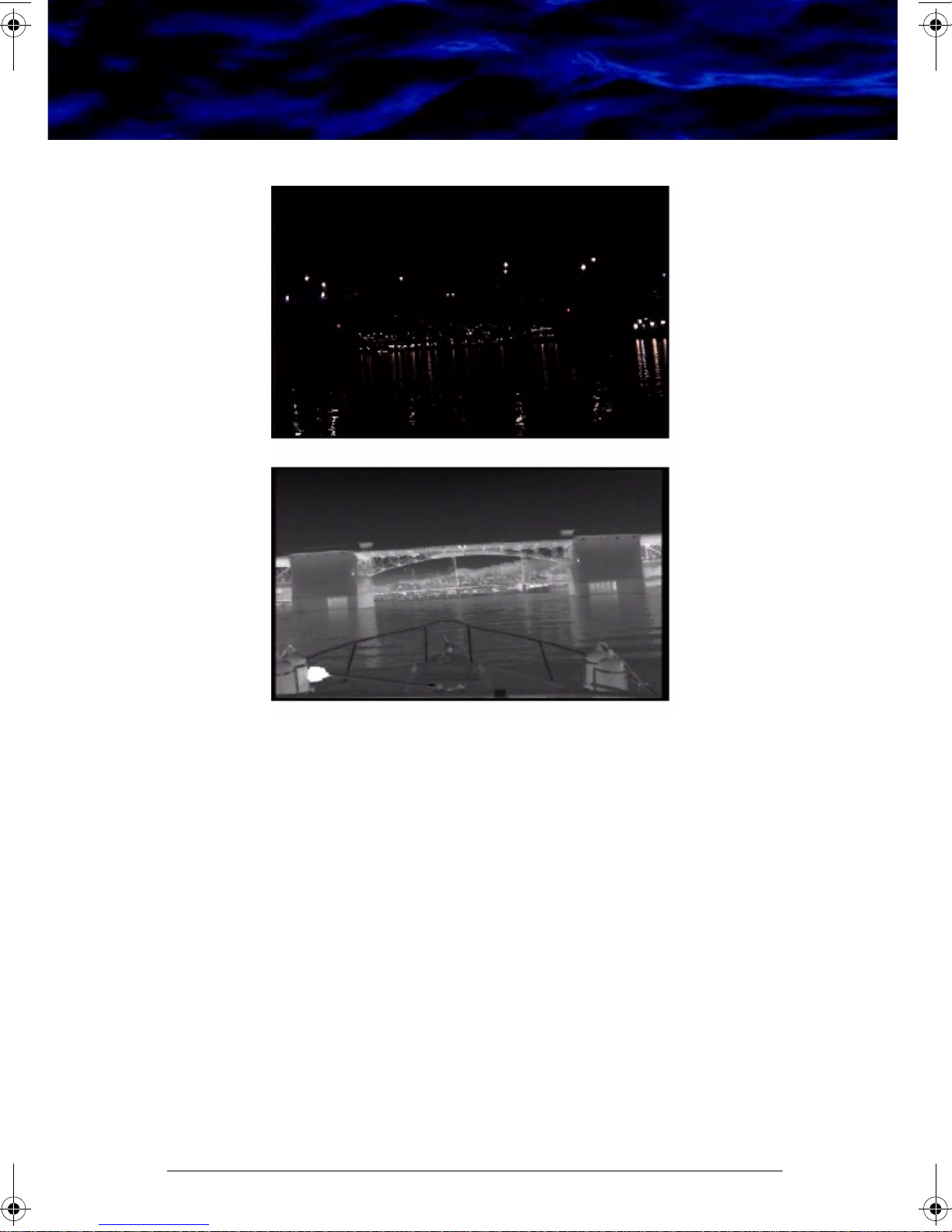
Figure 2-1: Mariner Makes the Difference
The upper image represents what the human eye sees during clear weather
night-time navigation. The lower image is a screen capture from a
ThermoVision
®
Mariner captured at the same moment as the visible image
above.
4 11/06 427-0010-00-10, version 120
Page 11
3 Getting Started
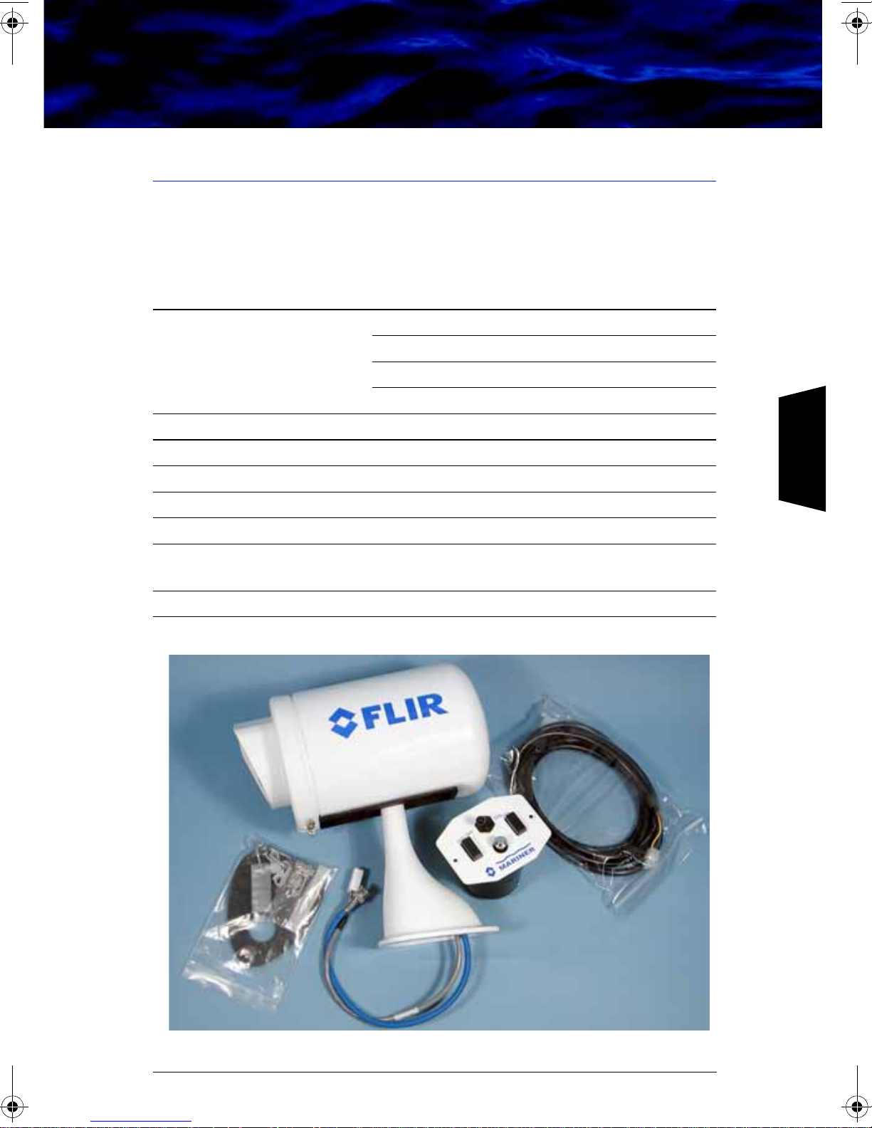
3.1 Parts List
The ThermoVision® Mariner camera and its accessories are delivered in a
box which contains the items below.
Description FLIR PN
Mariner camera white color, NTSC 427-0010-01-00
black color, NTSC 427-0010-03-00
white color, PAL 427-0010-04-00
black color, PAL 427-0010-06-00
Joystick control unit 333-0016-00-01
8’ Adapter cable—6 pin to 9 pin 308-0018-00
Mounting gasket
3
#8 x 1″ Stainless Steel Mounting Screws
#8 x ¼″ Stainless Steel Sheet Metal Screws
1 bag of electrical terminals, Joystick mounting
screws, and cable clips
Mariner Users Guide 427-0010-00-10
427-0010-00-10, version 120 11/06 5
Figure 3-1: Contents of the box
Page 12
3 – Getting Started
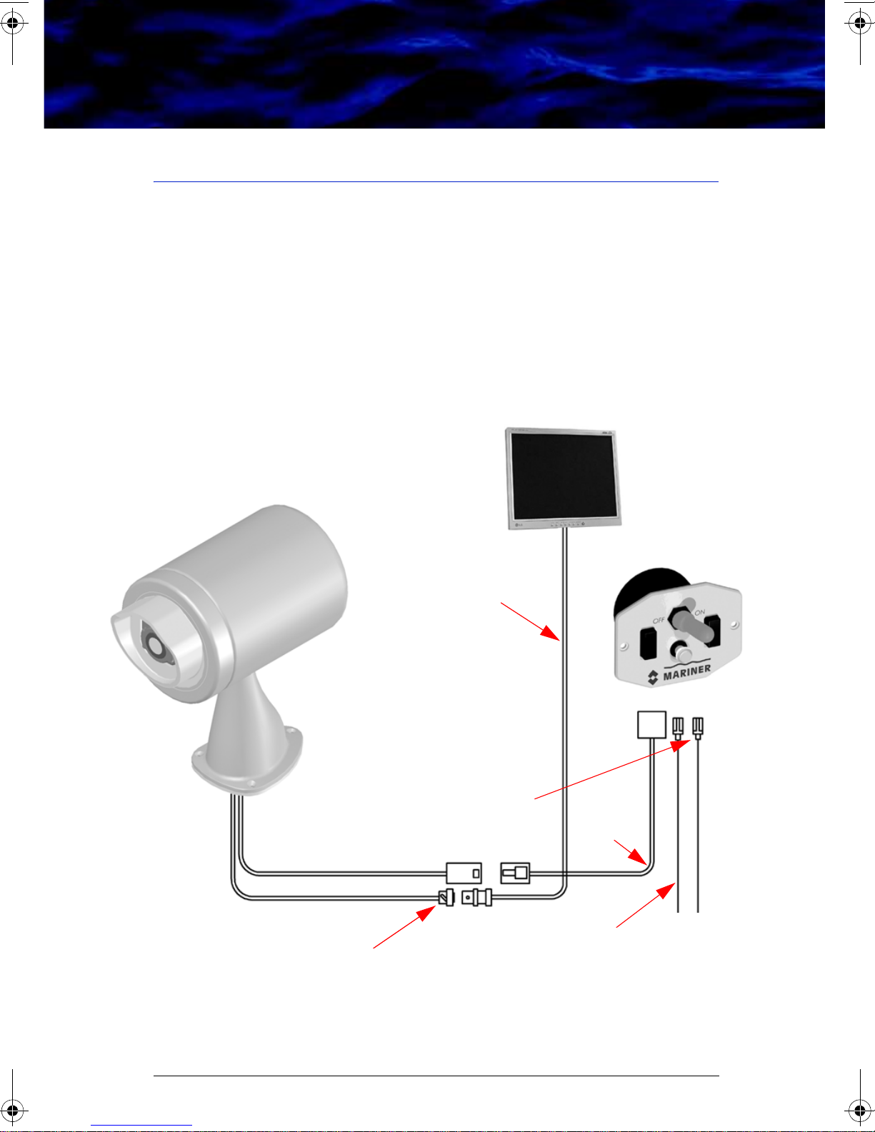
3.2 Operational Overview
The ThermoVision® Mariner is easy to install and operate. The system
operates on 12 volts DC, and the joystick control for panning and tilting
the camera is very intuitive; there are no camera adjustments. The thermal
imaging camera inside the ThermoVision
and extremely rugged. The camera has been qualified for operation in all
types of weather conditions over the specified operating temperature range
and includes an automatic window heater that will prevent icing under
most conditions.
Mariner Camera
with Pan/Tilt (supplied)
(not supplied)
®
Monitor
Mariner is completely sealed
BNC connector
75 ohm cable
(not supplied)
″ and 1/4″ spade
3/16
crimp connectors
(supplied)
Joystick Control
(supplied)
8’ cable
(included)
±12 Vdc, 20W
18 GA power wires
(not supplied)
Figure 3-2: Schematic of Standard Configuration
6 11/06 427-0010-00-10, version 120
Page 13
3 – Getting Started
Figure 3-2 defines the configuration for installations using one monitoring
station. Power is supplied to the Joystick Control Unit (JCU) and the
system is turned on and manipulated from this station. Locate the JCU in
an ergonomic position near the customer provided display. The JCU has a
small footprint and will accommodate a variety of installation
configurations. For most navigation needs, the ThermoVision
®
Mariner
pan/tilt head will face forward, and won’t be adjusted very often. But for
some applications, such as sport fishing, law enforcement, surveillance, or
fire fighting, extra consideration should be given to placement based on
the application and deck layouts.
The main sensor cable that links the JCU and the monitor is terminated on
both ends, but the installer is required to terminate the power cable at the
power source (ideally the fuse panel). This is the only electrical
termination required for a single monitor configuration.
3
427-0010-00-10, version 120 11/06 7
Page 14
3 – Getting Started
3.3 Installation
3.3.1 Camera Mounting
Caution! The ThermoVision
®
Mariner is intended to be mounted with the
pedestal flat and sealed to a horizontal surface with the camera above
the mounting plane. Any other type of installation is not appropriate and
could result in undesirable operation and will void the warranty.
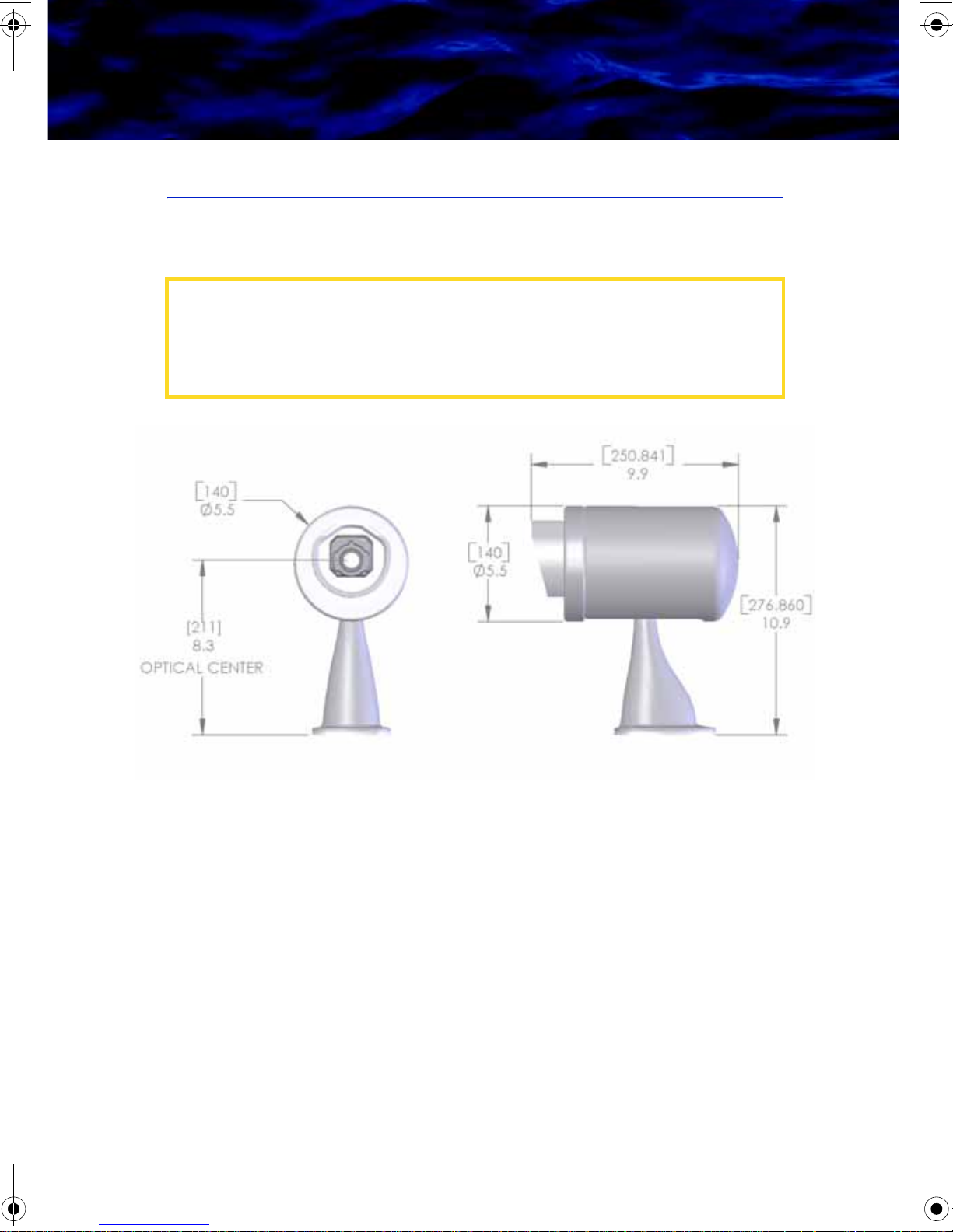
Mount the camera with the front of the base facing the intended viewing
direction. The camera base mounts with three #8 x 1″ flat head screws
which are provided.
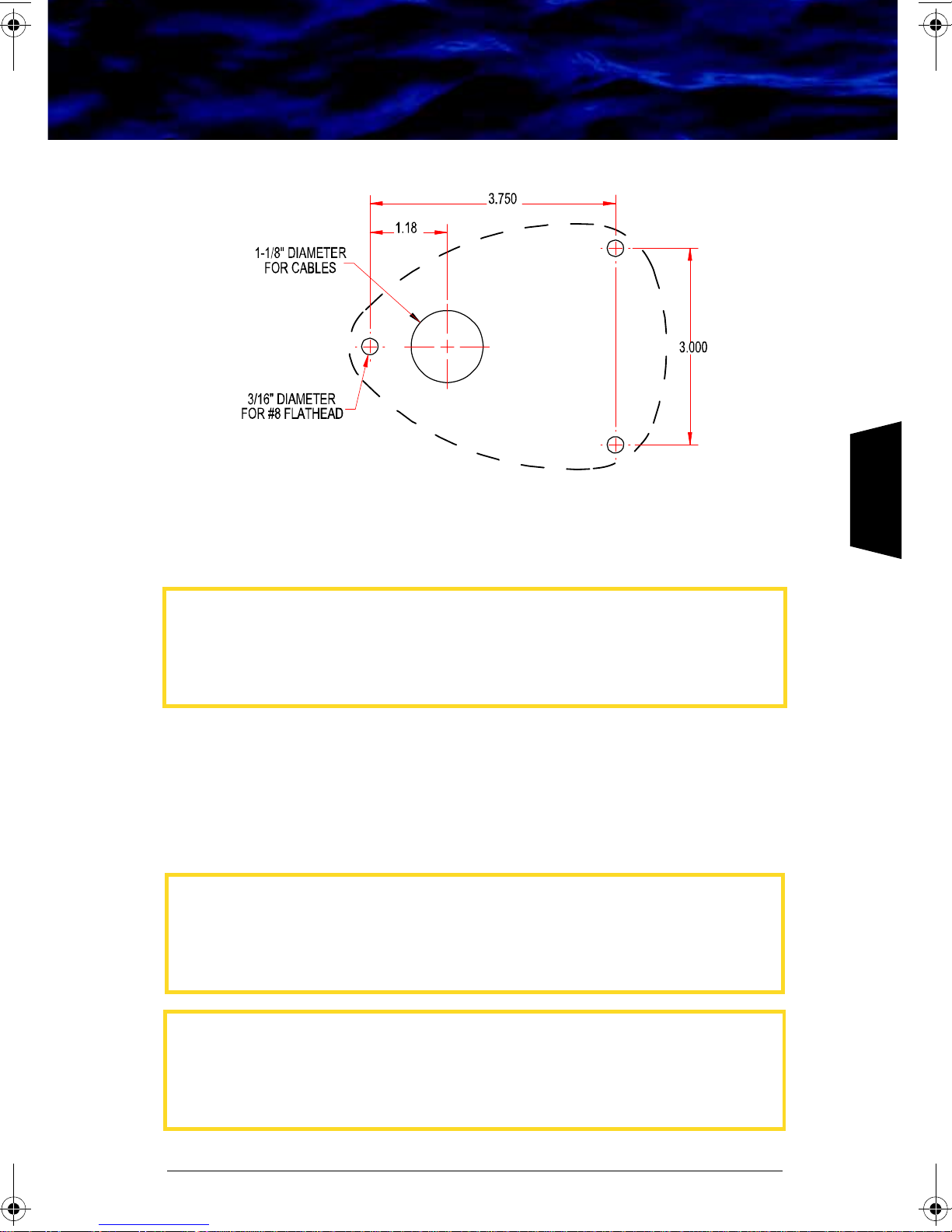
Step 1 Drill the screw mounting holes and 1.125″ cable through hole per
the installation template provided in Chapter 7 “Mounting
Templates” on page 25. A sketch is shown in Figure 3-4.
Step 2 With the gasket under the base, feed the cables through the hole
and fasten the camera in place using the three #8 x 1″ flat head
screws or three #8 x ¼″ sheet metal screws.
8 11/06 427-0010-00-10, version 120
Figure 3-3: Mariner Outline
Page 15
3 – Getting Started
Figure 3-4: Base Mount Template for Mariner Camera
3
3.3.2 Joystick Control Unit (JCU) Mounting
Caution! Changing the wiring configuration between the Joystick Control
Unit and the ThermoVision
or wiring harnesses other than the ones supplied by FLIR may cause
permanent damage to the unit and will void the warranty.
The unit may be mounted on any flat surface in any orientation.
Step 1 Cut a 3″ diameter hole in the surface where the control is to be
mounted using the template provided in Chapter 7 “Mounting
Templates” on page 25. A sketch is shown in Figure 3-5.
Caution! Do not connect the Mariner unit to anything other than 12V
power. Operating the camera outside of the specified input voltage
range or the specified operating temperature range can cause
permanent damage.
®
Mariner or attempting to utilize controllers
Caution! The ThermoVision
be used as the primary navigation system. It should be used in
conjunction with other navigation aids and a primary manual navigation
system.
427-0010-00-10, version 120 11/06 9
®
Mariner imaging system is not intended to
Page 16

3 – Getting Started
Figure 3-5: Joystick Control Unit Mounting Template
Step 2 Route power leads from the 12VDC power source in the fuse
protected main electrical panel to the control. Wire must be 16
gage with a maximum run of 100 feet.
Step 3 Crimp the terminals supplied onto the power leads. The larger
terminal is crimped to the positive lead, the smaller to the
negative. The terminals are clearly marked.
Step 4 Insert the wiring cable and power leads through the hole and plug
them into the control unit.
Step 5 Use bedding compound or sealant to waterproof the control
mounting.
Step 6 Secure the control with the self-tapping screws provided.
Step 7 Two 2 Ampere automotive type fuses are included in the control
unit as shown in Figure 3-6. The fuse on the left protects the
camera; the right fuse protects the pan-tilt motor circuit. See the
troubleshooting section of this User’s Guide for instructions on
replacing the fuses.
2 Amp fuses
10 11/06 427-0010-00-10, version 120
Figure 3-6: Joystick Control Unit
Page 17

3 – Getting Started
3.4 Using your new ThermoVision® Mariner
The ThermoVision® Mariner is easy to use, but you should take a moment
to carefully read this section so you fully understand what you are seeing
on your display. While the imagery you will see on the monitor may look
like black and white daylight video, it isn’t! A few tips on how to interpret
some of the imagery will help you to make the most of your system.
Turn on the camera using the on/off switch on the JCU. The joystick
controls the pan and tilt features of the camera. Controlling the camera’s
direction becomes intuitive after a few minutes of experimenting. The
camera automatically adjusts to changing scene conditions so no
additional camera control is necessary.
The thermal imager inside the camera does not sense light like
conventional cameras; it senses heat or temperature differences. As you
experiment with the system during daylight and nighttime operation, you
will notice differences in the “picture quality”; this is normal. The camera
senses small “differences” in apparent radiation from the objects in view,
and displays them as either white (or lighter shades of gray) for warmer
objects, and black (or darker shades of gray) for colder objects. This is why
you will see areas of other vessels under way such as exhaust stacks or
outboard engines that appear white, while the rest of the vessel may
appear dark (or cool). Scenes with familiar objects will be easy to interpret
with some experience. The camera automatically optimizes the image to
provide you with the best contrast in most conditions.
3
427-0010-00-10, version 120 11/06 11
Page 18

3 – Getting Started
When using the ThermoVision® Mariner as a navigation aid, keep an eye
out for objects in the water that may be appear only slightly warmer or
colder than the surrounding water. You will notice that in some cases, as in
Figure 3-7, you can see thermal reflections of warmer objects on the
water. Thermal (radiant) energy emitted by these objects that were warmed
by the sun during the day can be reflected by the water, in much the same
way sunlight can be reflected. Do not assume that the objects you are
looking for will be hot and therefore show up as white. Look for variations
or anomalies in scenes that you think would normally be the same
temperature.
Figure 3-7: Mariner showing thermal reflections on the water
In some cases, the composition of the object you are looking at can make
it look warmer or colder, and therefore be more or less obvious to your eye.
In Figure 3-8, you will see an object off the starboard bow that appears as
a small white line. This happens to be a log that was floating in the
Willamette River in November at about 7PM. Although this log was likely
the same temperature as the surrounding water, its composition makes it
appear white like a hot object. The important thing to note is that there is
clearly something in the water and you should carefully navigate to avoid a
collision. You can also see that there is a marker just off the port bow, at
about 100 yards.
12 11/06 427-0010-00-10, version 120
Page 19

3 – Getting Started
Figure 3-8: Mariner showing a log in the water,
a marker at range, and
a warm running light
As you experiment with your new ThermoVision® Mariner, you will see your
world in a different light. Consider every object you view in terms of how it
will look “thermally” as opposed to how it looks in the visible spectrum.
For example, when you first turn on your running lights, you may notice
that they don’t appear warm when viewed with the camera, but after some
time, show up white hot as they do in Figure 3-8. After sunset, objects
warmed by the sun will radiate for several hours and will appear warmest
right after sunset. Early in the morning, many of these objects will appear
cooler than their surroundings, so be sure to look for subtle differences in
the scene, as opposed to just hot (white) targets. If you have any questions
about the operation of your ThermoVision
®
Mariner, or you would like to
provide feedback on the product, please feel free to call us.
Caution! The user may experience degraded images during certain short
term atmospheric conditions such as those that allow water to condense
or collect on the camera window. These occurrences are temporary and
will not result in permanent degradation of the imaging system.
Because water droplets on the camera window temporarily reduce
performance, it is recommended to mount the ThermoVision
®
Mariner
in a location with minimal exposure to water splash or spray.
3
427-0010-00-10, version 120 11/06 13
Page 20

Page 21

4 Caring for your new ThermoVision® Mariner
4.1 Troubleshooting
Caution! Do not open the camera body for any reason. Disassembly of the
camera (including removal of the cover) can cause permanent damage
and will void the warranty.
If the camera will not produce an image or will not respond to JCU inputs,
check the fuses in the JCU by removing the fuse covers. If either or both of
the fuses have blown, replace them with 2 Ampere fuses.
If the JCU does not turn on when the power switch is turned on, check the
wiring at both the electrical panel and at the termination to the JCU.
Ensure that the contacts are clean dry and free from corrosion. If
maintenance on the wiring connection is required, have an authorized
service representative make the appropriate repairs.
If the camera will not produce an image, check the video connection at the
camera and at your display. If the connectors appear to be properly
engaged but the camera still does not produce an image, have an
authorized service representative make the appropriate repairs.
4
427-0010-00-10, version 120 11/06 15
Page 22

4 – Caring for your new ThermoVision® Mariner
4.2 Replacing the fuses
Caution! Do not open the camera body for any reason. Disassembly of the
camera (including removal of the cover) can cause permanent damage
and will void the warranty.
Caution! Replace system fuses with the same value and type provided
at the time of purchase. Using fuse values other than the ones supplied
by FLIR may cause permanent damage to the unit and will void the
warranty.
To replace the Joystick control unit fuses, remove the covers and replace
those using 2 Ampere automotive fuses.
Figure 4-1: Mariner Joystick Control Unit Fuses
16 11/06 427-0010-00-10, version 120
Page 23

4 – Caring for your new ThermoVision® Mariner
4.2.1 Cleaning
Caution! The camera window has an anti-reflective coating and should
be cleaned only with low pressure fresh water and a non-abrasive. cloth.
The camera housing has a durable marine coating. Rinse the camera
housing with very low pressure fresh water to keep it clean. If the front
window of the Mariner gets water spots, wipe it with a clean lens tissue
folded in fourths dampened with fresh water.
Front
Window
Figure 4-2: Mariner Front Window
4
427-0010-00-10, version 120 11/06 17
Page 24

Page 25

5 Options and Accessories
5.1 Mariner Dual Control Station Accessory Kit
FLIR Systems makes available an optional Remote Dual Control Accessory
Kit. This Kit allows for a control and output display at a location remote
from the primary control location. This Remote Accessory Kit, FLIR PN
333-0015-00 consists of the following parts:
Description FLIR PN
Secondary Joystick Control unit 333-0016-00-01
Dual Control Selector Switch 333-0016-00-02
Video Amplifier/Splitter 333-0016-00-03
25’ Extension Cable 308-0112-00-05
Figure 5-1: Figure 9: Remote Accessory Kit
5
427-0010-00-10, version 120 11/06 19
Page 26

5 – Options and Accessories
5.2 Dual Control Selector Mounting
Mount the dual control selector switch unit near the primary joystick
control (the maximum cable length available between the switch and the
joystick unit is about 15″ , and the existing cable from the camera must be
able to reach the control selector switch unit).
Step 1 Cut a 1-1/2″ diameter hole for the switch unit.
Step 2 Route the existing camera cable to the switch unit.
Step 3 Route the secondary control cable (and extensions if needed) from
the switch unit to the secondary joystick control location.
Step 4 Insert the dual control selector switch panel through the mounting
hole and attach connectors to the mating connectors.
Step 5 Use bedding compound or sealant to waterproof the switch panel.
Step 6 Secure the switch unit with the self-tapping screws provided.
Figure 5-2: Dual Control Selector Mounting Template
20 11/06 427-0010-00-10, version 120
Page 27

5 – Options and Accessories
Figure 5-3 shows the cable configuration for dual JCU.
Monitors
(not supplied)
Mariner Camera
with Pan/Tilt (supplied)
Joystick Control
(supplied)
Dual Control
Selector
(supplied)
Joystick Control
(supplied)
BNC to “F” Type
Adaptor (supplied)
Figure 5-3: Schematic of Dual Control Configuration
±12 Vdc, 20W
75 ohm cables
(not supplied)
Video Splitter/Amplifier
(supplied)
±12 Vdc, 20W
5
427-0010-00-10, version 120 11/06 21
Page 28

5 – Options and Accessories
5.3 Optional Extension Cables
FLIR Systems makes available a family of JCU extension cables. The
cables may be combined to a total length of 100 feet. The part numbers
are as follows:
Description FLIR PN
10’ Mariner Joystick Extension Cable 308-0112-00-01
15’ Mariner Joystick Extension Cable 308-0112-00-03
25’ Mariner Joystick Extension Cable 308-0112-00-05
35’ Mariner Joystick Extension Cable 308-0112-00-07
50’ Mariner Joystick Extension Cable 308-0112-00-09
22 11/06 427-0010-00-10, version 120
Page 29

6 Technical Data
6.1 Performance Specification
Thermal Imaging Performance
Sensor type 320 x 240 uncooled microbolometer
Field of view 36× h x 27× v
Spectral band 8 - 14 μ
Pan/Tilt
Az range 370°
El range -30° to +30°
Outputs
Video NTSC or PAL
Connector types BNC at primary cable end (requires video
amplifier for multiple monitor applications)
Power
Power requirements 12 Vdc
Power consumption 20 Watts (max)
Environmental
Operating temperature -10°C to 55° C
Storage temperature -40° C to 70° C
Dimensions and Weight
Dimensions 308 x 229 (12″ d x 9″ h)
Weight 4 kg (8.8 lb.)
6
427-0010-00-10, version 120 11/06 23
Page 30

Page 31

7 Mounting Templates
7.1 Camera Mounting Template.
Camera View Direction
7
For installation purposes, a tear out version of this page
is located at the very back of this manual.
427-0010-00-10, version 120 11/06 25
Page 32

Page 33

7.2 Joystick Mounting Template
3.500
3.000
7 – Mounting Templates
0.120
#31 DRILL
2 PLACES
For installation purposes, a tear out version of this page
is located at the very back of this manual.
7
427-0010-00-10, version 120 11/06 27
Page 34

Page 35

8 Infrared Technology
8.1 History of Infrared
Less than 200 years ago the existence of the infrared portion of the
electromagnetic spectrum wasn't even suspected. The original significance
of the infrared spectrum, or simply ‘the infrared’ as it is often called, as a
form of heat radiation is perhaps less obvious today than it was at the time
of its discovery by Herschel in 1800.
Figure 8-1: Sir William Herschel (1738–1822)
The discovery was made accidentally during the search for a new optical
material. Sir William Herschel—Royal Astronomer to King George III of
England, and already famous for his discovery of the planet Uranus—was
searching for an optical filter material to reduce the brightness of the sun’s
image in telescopes during solar observations. While testing different
samples of colored glass which gave similar reductions in brightness he
was intrigued to find that some of the samples passed very little of the
sun’s heat, while others passed so much heat that he risked eye damage
after only a few seconds’ observation.
Herschel was soon convinced of the necessity of setting up a systematic
experiment, with the objective of finding a single material that would give
the desired reduction in brightness as well as the maximum reduction in
heat. He began the experiment by actually repeating Newton’s prism
experiment, but looking for the heating effect rather than the visual
distribution of intensity in the spectrum. He first blackened the bulb of a
sensitive mercury-in-glass thermometer with ink, and with this as his
radiation detector he proceeded to test the heating effect of the various
colors of the spectrum formed on the top of a table by passing sunlight
through a glass prism. Other thermometers, placed outside the sun’s rays,
served as controls.
8
427-0010-00-10, version 120 11/06 29
Page 36

8 – Infrared Technology
As the blackened thermometer was moved slowly along the colors of the
spectrum, the temperature readings showed a steady increase from the
violet end to the red end. This was not entirely unexpected, since the
Italian researcher, Landriani, in a similar experiment in 1777 had
observed much the same effect. It was Herschel, however, who was the
first to recognize that there must be a point where the heating effect
reaches a maximum, and those measurements confined to the visible
portion of the spectrum failed to locate this point.
Figure 8-2: Marsilio Landriani (1746–1815)
Moving the thermometer into the dark region beyond the red end of the
spectrum, Herschel confirmed that the heating continued to increase. The
maximum point, when he found it, lay well beyond the red end—in what is
known today as the ‘infrared wavelengths’.
When Herschel revealed his discovery, he referred to this new portion of
the electromagnetic spectrum as the ‘thermometrical spectrum’. The
radiation itself he sometimes referred to as ‘dark heat’, or simply ‘the
invisible rays’. Ironically, and contrary to popular opinion, it wasn't
Herschel who originated the term ‘infrared’. The word only began to appear
in print around 75 years later, and it is still unclear who should receive
credit as the originator.
Herschel’s use of glass in the prism of his original experiment led to some
early controversies with his contemporaries about the actual existence of
the infrared wavelengths. Different investigators, in attempting to confirm
his work, used various types of glass indiscriminately, having different
transparencies in the infrared. Through his later experiments, Herschel
was aware of the limited transparency of glass to the newly-discovered
thermal radiation, and he was forced to conclude that optics for the
infrared would probably be doomed to the use of reflective elements
exclusively (i.e. plane and curved mirrors). Fortunately, this proved to be
30 11/06 427-0010-00-10, version 120
Page 37

8 – Infrared Technology
true only until 1830, when the Italian investigator, Melloni, made his great
discovery that naturally occurring rock salt (NaCl)—which was available in
large enough natural crystals to be made into lenses and prisms—is
remarkably transparent to the infrared. The result was that rock salt
became the principal infrared optical material, and remained so for the
next hundred years, until the art of synthetic crystal growing was mastered
in the 1930’s.
Figure 8-3: Macedonio Melloni (1798–1854)
Thermometers, as radiation detectors, remained unchallenged until 1829,
the year Nobili invented the thermocouple. (Herschel’s own thermometer
could be read to 0.2 °C (0.036 °F), and later models were able to be read
to 0.05 °C (0.09 °F)). Then a breakthrough occurred; Melloni connected a
number of thermocouples in series to form the first thermopile. The new
device was at least 40 times as sensitive as the best thermometer of the
day for detecting heat radiation—capable of detecting the heat from a
person standing three meters away.
The first so-called ‘heat-picture’ became possible in 1840, the result of
work by Sir John Herschel, son of the discoverer of the infrared and a
famous astronomer in his own right. Based upon the differential
evaporation of a thin film of oil when exposed to a heat pattern focused
upon it, the thermal image could be seen by reflected light where the
interference effects of the oil film made the image visible to the eye. Sir
John also managed to obtain a primitive record of the thermal image on
paper, which he called a ‘thermograph’.
427-0010-00-10, version 120 11/06 31
8
Page 38

8 – Infrared Technology
Figure 8-4: Samuel P. Langley (1834–1906)
The improvement of infrared-detector sensitivity progressed slowly.
Another major breakthrough, made by Langley in 1880, was the invention
of the bolometer. This consisted of a thin blackened strip of platinum
connected in one arm of a Wheatstone bridge circuit upon which the
infrared radiation was focused and to which a sensitive galvanometer
responded. This instrument is said to have been able to detect the heat
from a cow at a distance of 400 meters.
An English scientist, Sir James Dewar, first introduced the use of liquefied
gases as cooling agents (such as liquid nitrogen with a temperature of 196 °C (-320.8 °F)) in low temperature research. In 1892 he invented a
unique vacuum insulating container in which it is possible to store
liquefied gases for entire days. The common ‘thermos bottle’, used for
storing hot and cold drinks, is based upon his invention.
Between the years 1900 and 1920, the inventors of the world ‘discovered’
the infrared. Many patents were issued for devices to detect personnel,
artillery, aircraft, ships—and even icebergs. The first operating systems, in
the modern sense, began to be developed during the 1914–18 war, when
both sides had research programs devoted to the military exploitation of
the infrared. These programs included experimental systems for enemy
intrusion/detection, remote temperature sensing, secure communications,
and ‘flying torpedo’ guidance. An infrared search system tested during this
period was able to detect an approaching airplane at a distance of 1.5 km
(0.94 miles), or a person more than 300 meters (984 ft.) away.
The most sensitive systems up to this time were all based upon variations
of the bolometer idea, but the period between the two wars saw the
development of two revolutionary new infrared detectors: the image
32 11/06 427-0010-00-10, version 120
Page 39

8 – Infrared Technology
converter and the photon detector. At first, the image converter received
the greatest attention by the military, because it enabled an observer for
the first time in history to literally ‘see in the dark’. However, the
sensitivity of the image converter was limited to the near infrared
wavelengths, and the most interesting military targets (i.e. enemy soldiers)
had to be illuminated by infrared search beams. Since this involved the
risk of giving away the observer’s position to a similarly-equipped enemy
observer, it is understandable that military interest in the image converter
eventually faded.
The tactical military disadvantages of so-called 'active’ (i.e. search beamequipped) thermal imaging systems provided impetus following the 1939–
45 war for extensive secret military infrared-research programs into the
possibilities of developing ‘passive’ (no search beam) systems around the
extremely sensitive photon detector. During this period, military secrecy
regulations completely prevented disclosure of the status of infraredimaging technology. This secrecy only began to be lifted in the middle of
the 1950’s, and from that time adequate thermal-imaging devices finally
began to be available to civilian science and industry.
427-0010-00-10, version 120 11/06 33
8
Page 40

8 – Infrared Technology
8.2 How do Infrared Cameras Work?
Infrared energy is part of a complete range of radiation called the
electromagnetic spectrum. The electromagnetic spectrum includes gamma
rays, X-rays, ultraviolet, visible, infrared, microwaves (RADAR), and radio
waves. The only difference between these different types of radiation is
their wavelength or frequency. All of these forms of radiation travel at the
speed of light (186,000 miles or 300,000,000 meters per second in a
vacuum). Infrared radiation lies between the visible and RADAR portions
of the electromagnetic spectrum. Thus infrared waves have wavelengths
longer than visible and shorter than RADAR.
Figure 8-5: Electromagnetic Spectrum
The primary source of infrared radiation is heat or thermal radiation. Any
object which has a temperature radiates in the infrared portion of the
electromagnetic spectrum. Even objects that are very cold, such as an ice
cube, emit infrared. When an object is not quite hot enough to radiate
visible light, it will emit most of its energy in the infrared. For example, hot
charcoal may not give off light, but it does emit infrared radiation which
we feel as heat. The warmer the object, the more infrared radiation it
emits.
Infrared cameras produce an image of invisible infrared or “heat” radiation
that is unseen by the human eye. There are no colors or “shades” of gray
34 11/06 427-0010-00-10, version 120
Page 41

8 – Infrared Technology
in infrared, only varying intensities of radiated energy. The infrared imager
converts this energy into an image that we can interpret. Several detector
technologies exist; the sensor in the ThermoVision
®
Mariner is of the latest
solid state design, offering long life and fully automatic image
optimization (contrast and gain). True thermal imagers should not be
confused with infrared illuminator cameras that are often presented as
simply “infrared cameras.” There are hundreds of low cost infrared
illuminated cameras on the market at prices below $100. These cameras
do not produce the same image because they do not detect heat. They
operate in wavelengths near visible, and require an IR illuminator to
provide an image. IR illuminators have very short range, and require a lot
of power to see beyond 5 meters.
427-0010-00-10, version 120 11/06 35
8
Page 42

Page 43

Tear out here
Camera View Direction
Full size Mariner Mounting Template
Page 44

Page 45

Tear out here
3.500
3.000
0.120
#31 DRILL
2 PLACES
Full size Joystick Mounting Template
Page 46

Page 47

Page 48

SANTA BARBARA
CVS World Headquarters
FLIR Systems, Inc.
Indigo Operations
70 Castilian Dr.
Goleta, CA 93117
USA
PH: +1 888.747.3547
FX: +1 805.685.2711
NETHERLANDS
CVS Eurasian Headquarters
FLIR Systems CVS BV
Verlengde Poolseweg 34-46
4818 CL Breda
Netherlands
PH: +31 (0) 76.524.46.86
PH: +31 (0) 475.60.12.49
FX: +31 (0) 76.524.46.66
PORTLAND
Corporate Headquarters
FLIR Systems, Inc.
27700A SW Parkway Ave.
Wilsonville, OR 97070
USA
PH: +1 503.498.3547
PH: +1 800.727.3547
FX: +1 503.498.3904
BOSTON
FLIR Systems Boston, Inc.
25 Esquire Road
North Billerica, MA 01862
USA
PH: +1 978.901.8000
PH: +1 800.GO.INFRA
FX: +1 978.901.8885
www.flir.com
 Loading...