

Page 1
User and
Installation
Guide
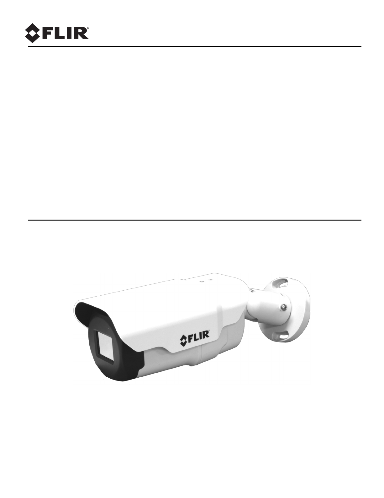
FB-Series
FB-Series O
Page 2

© 2017 FLIR Systems, Inc. All rights reserved worldwide. No parts of this manual, in whole or in part, may be
copied, photocopied, translated, or transmitted to any electronic medium or machine readable form without the
prior written permission of FLIR Systems, Inc.
Names and marks appearing on the products herein are either registered trademarks or trademarks of FLIR
Systems, Inc. and/or its subsidiaries. All other trademarks, trade names, or company names referenced herein are
used for identification only and are the property of their respective owners.
This product is protected by patents, design patents, patents pending, or design patents pending.
The contents of this document are subject to change without notice.
For additional information visit www.flir.com or write to FLIR Systems, Inc.
FLIR Systems, Inc.
6769 Hollister Avenue
Goleta, CA 93117
Support: http://www.flir.com/security/display/?id=71083.
Important Instructions and Notices to the User:
This device complies with part 15 of the FCC Rules. Operation is subject to the following two conditions: (1) This
device may not cause harmful interference, and (2) this device must accept any interference received, including
interference that may cause undesired operation.
Modification of this device without the express authorization of FLIR Systems, Inc. may void the user’s authority
under FCC rules to operate this device.
Note 1: This equipment has been tested and found to comply with the limits for a Class A digital device, pursuant to
part 15 of the FCC Rules. These limits are designed to provide reasonable protection against harmful interference
when the equipment is operated in a commercial environment. This equipment generates, uses, and can radiate
radio frequency energy and, if not installed and used in accordance with the instruction manual, may cause harmful
interference to radio communications. Operation of this equipment in a residential area is likely to cause harmful
interference in which case the user will be required to correct the interference at the user’s own expense.
Note 2: If this equipment came with shielded cables, it was tested for compliance with the FCC limits for a Class A
digital device using shielded cables and therefore shielded cables must be used with the device
Industry Canada Notice:
This Class A digital apparatus complies with Canadian ICES-003.
Avis d’Industrie Canada:
Cet appareil numérique de la classe A est conforme à la norme NMB-003 du Canada.
Proper Disposal of Electrical and Electronic Equipment (EEE)
The European Union (EU) has enacted Waste Electrical and Electronic Equipment Directive 2002/
96/EC (WEEE), which aims to prevent EEE waste from arising; to encourage reuse, recycling, and
recovery of EEE waste; and to promote environmental responsibility.
In accordance with these regulations, all EEE products labeled with the “crossed out wheeled bin”
either on the product itself or in the product literature must not be disposed of in regular rubbish bins,
mixed with regular household or other commercial waste, or by other regular municipal waste
collection means. Instead, and in order to prevent possible harm to the environment or human
health, all EEE products (including any cables that came with the product) should be responsibly
discarded or recycled.
To identify a responsible disposal method nearby, please contact the local waste collection or recycling service, the
original place of purchase or product supplier, or the responsible government authority in the area. Business users
should contact their supplier or refer to their purchase contract.
Document History
Version Date Comment
100 August 2017 Initial Release
Page 3

Table of Contents
Ta b l e o f C on te nt s
Camera Installation
1.1 Warnings and Cautions ............................................................................................... 5
1.2 References .................................................................................................................. 5
1.3 Installation Overview ................................................................................................... 6
1.3.1 Camera Connection Options .............................................................................. 6
1.3.2 Supplied Components ........................................................................................ 6
1.3.3 Additional Supplies ............................................................................................. 6
1.3.4 Mounting Accessories ........................................................................................ 7
1.3.5 Site Preparation .................................................................................................. 7
1.3.6 Camera Placement ............................................................................................. 8
1.3.7 Camera Mounting ............................................................................................... 9
1.4 Camera Connections ................................................................................................... 9
1.4.1 Bench Testing .................................................................................................. 10
1.4.2 Analog Video Connections ............................................................................... 10
1.4.3 Connecting Power ............................................................................................ 10
1.4.4 Alarm Connections—Not supported ................................................................. 11
1.4.5 Ethernet ............................................................................................................ 11
1.4.6 Camera Grounding ........................................................................................... 11
1.5 Mounting the Camera ................................................................................................ 11
1.6 Camera specifications ............................................................................................... 12
Basic Operation and Configuration
2.1 IP Camera, ONVIF Profile S Compliant .................................................................... 13
2.2 Set IP Address using the FLIR Discovery Network Assistant (DNA) ........................ 14
2.3 Camera Bench Test .................................................................................................. 15
2.3.1 Log in to the Camera Web Page ...................................................................... 15
2.3.2 Live Video Page ............................................................................................... 16
2.4 Basic Camera Configuration ..................................................................................... 18
2.4.1 Setup Menu ...................................................................................................... 18
2.4.2 Server Menu ..................................................................................................... 18
2.5 Thermal Imaging Overview ....................................................................................... 23
2.6 Maintenance and Troubleshooting Tips .................................................................... 23
427-0064-00-12, Version 100 August 2017 3
Page 4

Table of Contents
Image from a standard camera in low light
Image from a thermal camera in the same
conditions
Advanced Configuration
3.1 Setup Menu ...............................................................................................................27
3.1.1 Video Setup ...................................................................................................... 28
3.1.2 Thermal Image Setup ....................................................................................... 29
3.2 Maintenance Menu .................................................................................................... 31
3.2.1 Sensor Menu .................................................................................................... 31
3.2.2 Files Menu ........................................................................................................ 33
3.2.3 Product Info Menu ............................................................................................ 34
427-0064-00-12 Version 100 August 2017 4
Page 5

1 Camera Installation
This manual describes the installation and initial configuration of the FB-Series O thermal cameras.
If help is needed during the installation process, contact the local FLIR service representative or call
the appropriate support number listed at: http://www.flir.com/security/display/?id=71083.
All installers and integrators are encouraged to take advantage of the training offered by FLIR; visit
http://www.flir.com/training for more information.
This manual includes the following topics:
• Installation overview
• Camera mounting accessories
• Mounting the camera and its components
• Connecting the electronics
• Bench testing the camera
• Basic configuration and operation of the camera
• Camera specifications
For safety, and to achieve the highest levels of performance from the FB-Series O camera system,
always follow the warnings and cautions in this manual when handling and operating the camera.
1.1 Warnings and Cautions
Warning!
If mounting the FB-Series O camera on a pole, tower or any elevated location, use industry standard
safe practices to avoid injuries.
Caution!
Except as described in this manual, do not open the FB-Series O camera for any reason. Damage to
the camera can occur as the result of careless handling or electrostatic discharge (ESD). Always
handle the camera with care to avoid damage to electrostatic-sensitive components.
Prior to making any connections, ensure the power supply or circuit breaker is switched off.
Be careful not to leave fingerprints on the FB-Series O camera’s infrared optics.
Operating the camera outside of the specified input voltage range or the specified operating
temperature range can cause permanent damage.
1.2 References
FLIR Doc # 427-0030-00-28 Nexus IP Camera Configuration Guide, provides more information on
setting or changing camera parameters.
Documents are available from the FLIR website.
427-0064-00-12, Version 100 August 2017 5
Page 6
1 Camera Installation
1.3 Installation Overview
The FB-Series O camera is an infrared thermal imaging camera intended for indoor or outdoor
security applications while installed in a fixed location. The camera mounting must support up to 5.4
lbs (2.5 kg). Refer to
from FLIR Systems, Inc.
1.3.1 Camera Connection Options
The FB-Series O camera can be installed with an analog or digital (IP) video output (or both). Analog
video requires a connection to a video monitor or an analog video matrix switch. The camera can be
powered using Power over Ethernet (PoE) or with a conventional 24 Vac or 12 Vdc power supply. For
a PoE connection, an accessory PoE power supply (also called a PoE injector) is required if the
camera is not connected to a PoE switch. The maximum Ethernet cable run is 100 meters including
the PoE power supply. In installations using PoE power and IP video, only a single Ethernet cable to
the camera is required. The FB-Series
802.3af-2003 standard.
Mounting Accessories, pg. 7 for wall and pole mounts that can be purchased
O camera is a Powered Device compliant with the IEEE
In installations using analog video and conventional power, an RG59U coaxial cable and a power
cable are installed. It is recommended an Ethernet cable should also be installed for camera
configuration and troubleshooting. The FB-Series
O camera does not support serial communications.
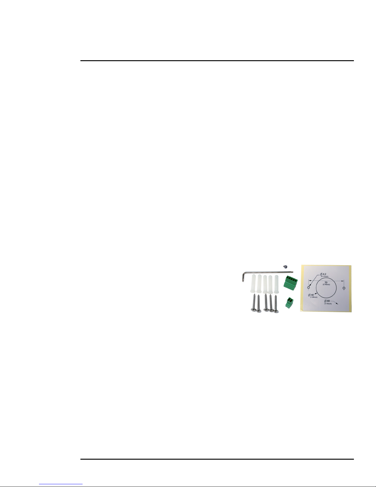
1.3.2 Supplied Components
The FB-Series O camera package includes these standard components:
• Fixed Camera Unit with sun shield and cable pigtail
• Power terminal block, if not using PoE
• Accessory terminal block—not supported
• Five plastic screw anchors
• Five screws
• Tools: Torx wrench to remove cover and
spare Torx cover screw
• Installation Template
1.3.3 Additional Supplies
The installer may need to supply the following items as required (specific to the installation).
• Power supply, 24 Vac or 12 Vdc if not using PoE power for system power.
• Power cable, 2-conductor, gauge determined by cable length and supply voltage,
if used for system power
• PoE power supply or PoE switch, if used for system power.
• Cat5e or Cat6 Ethernet cable for digital video and/or PoE for system power
• Coaxial RG59U cables (BNC connector at the camera end) for analog video
• Camera grounding strap, camera mount, electrical hardware, connectors, and tools
427-0064-00-12 Version 100 August 2017 6
Page 7
1 Camera Installation
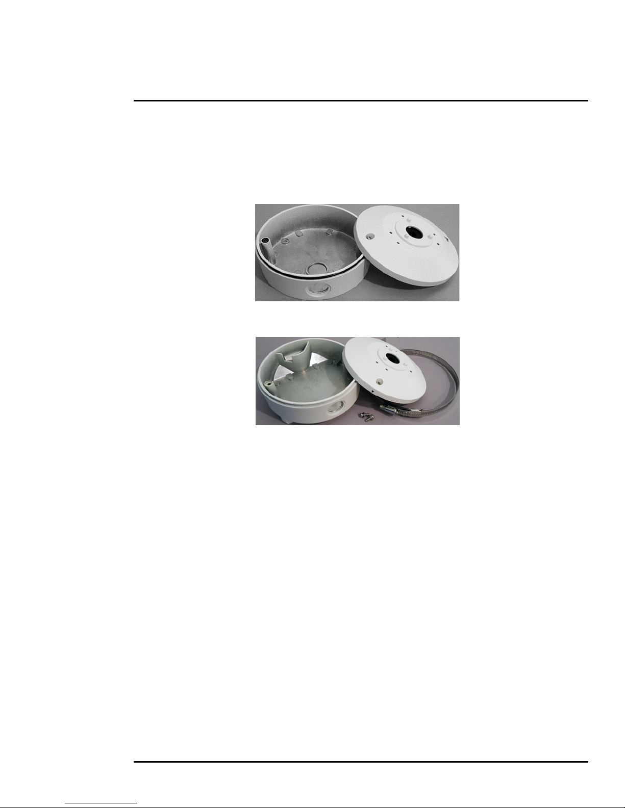
Wall Mount Junction Box CB-WLBX-62
Pole Mount Junction Box CB-PLBX-62
1.3.4 Mounting Accessories
The following mounting accessories are available from FLIR Systems, Inc. for installing the
FB-Series
O camera. For more information on available options, contact your FLIR sales
representative or visit www.FLIR.com/security to request details on where to get the accessories you
need.
1.3.5 Site Preparation
There are several requirements to address prior to installation at the site. The following
recommendations provide for proper installation and operation of the unit. Adhere to all local and
industry standards, codes, and best practices.
• Ambient Environment Conditions: Avoid positioning the unit near heaters or heating system
outputs. Avoid exposure to direct sunlight.
• Safety: Cables and electrical cords should be routed in a manner that prevents safety hazards.
Ensure that nothing rests on the unit’s cables or power cords.
• Ample Air Circulation: Leave enough space around the unit to allow free air circulation.
• Cabling Considerations: Using a cable longer than the manufacturer’s specifications for optimal
video signal may result in degradation of color and video parameters.
• Physical Security: The unit provides threat detection for physical security systems. In order to
ensure that the unit cannot be disabled or tampered with, the system should be installed with
security measures regarding physical access by trusted and untrusted parties.
• Network Security: The unit transmits over IP to security personnel for video surveillance. Proper
network security measures should be in place to assure networks remain operating and free from
malicious interference. Install the unit on the backbone of a trusted network.
• Electrostatic Discharge Safeguards: The unit and other equipment connected to it (relay
outputs, alarm inputs, racks, carpeting, etc.) shall be properly grounded to prevent electrostatic
discharge.
427-0064-00-12 Version 100 August 2017 7
Page 8
1 Camera Installation
α
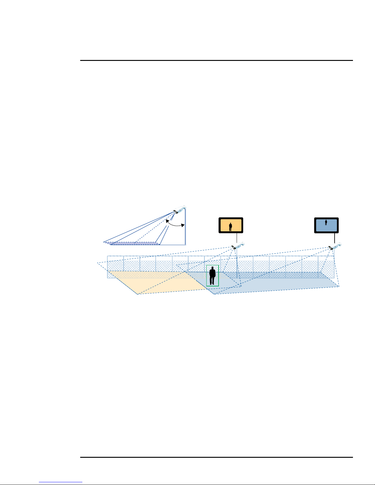
1.3.6 Camera Placement
Although the FB-Series O camera does not have on-board video analytics, many video management
systems and video encoders analyze the video signals to send alarm notifications based on
customized rules. Several types of third-party Video Management Systems (VMS) are supported by
FLIR IP cameras. Because these systems tend to evolve and change over time, contact the local
FLIR representative or FLIR Technical Support for information.
For installations with multiple cameras, the fields of view of cameras should overlap in order to
remove all dead zones in which a camera cannot see a target “head to toe”.
• Install the camera at a height of approximately 4 m (13 ft) or more.
• Typically direct the camera towards the ground with a tilt angle α within a range of 45° to 60°
while ensuring the field of view includes as little of the skyline as possible.
• Ensure that cameras are mounted on stable mounts with minimal vibrations and maximal
resistance to wind.
• The tilt angle (α) is the angle between vertical and the center of the camera field of view.
427-0064-00-12 Version 100 August 2017 8
Page 9
1 Camera Installation
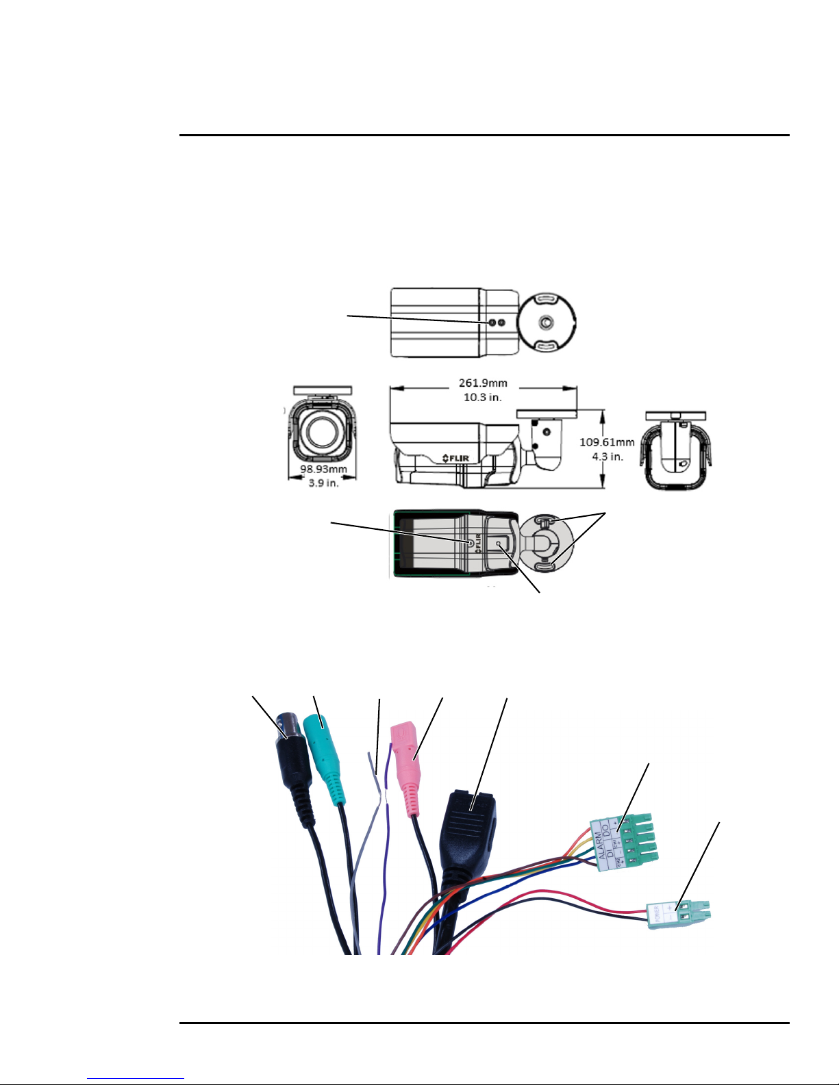
Figure 1-1: FB-Series O Camera Mounting
1/4-20 bottom mount
4.2 mm (0.17 in.) slot
bracket mount
Sunshield
screws (x2)
Front cover screw
1
7
6
5234
1.3.7 Camera Mounting
The FB-Series O camera can be mounted with two fasteners in the bracket slots. Alternatively, the
camera can be mounted with a 1/4-20 threaded fastener on the bottom of the camera.
If using the 1/4-20 fastener on the bottom of the camera, the maximum depth of the fastener should
not exceed 10.0 mm (0.4 in).
1.4 Camera Connections
Refer to Table 1-1 for a description of these camera connections.
427-0064-00-12 Version 100 August 2017 9
Page 10

1 Camera Installation
Figure 1-3: Power Connector
12
1 BNC Analog video
2 Green barrel not supported
Ta b l e 1-1: FB-Series O Camera Connections
Connection Purpose
3
4 Pink barrel not supported
5 Ethernet PoE power, communications, IP video stream
6 5-pin plug not supported
7 2-pin plug Vac o r Vdc p owe r
Purple D-
not supported
Grey D+
1.4.1 Bench Testing
Note
If the camera is to be mounted on a pole or tower or other hard-to-reach location, connect and
operate the camera as a bench test prior to mounting the camera in its final location.
Connect the power, Ethernet, and video, and confirm that the video can be displayed on a monitor
when the power is turned on. For configuration and basic setup information using the on-board web
server, refer to
Camera Bench Test, pg. 15 for specific details.
1.4.2 Analog Video Connections
The primary analog video connection of the camera is a BNC connector. The video cable used
should be rated as RG-59/U or better to ensure a quality video signal.
1.4.3 Connecting Power
The camera can be powered with a conventional 24 Vac or 12 Vdc
power supply, rather than PoE. Prior to making any connections,
ensure the power supply or circuit breaker is switched off.
The camera itself does not have an on/off switch. Generally the
FB-Series
the circuit breaker will be used to apply or remove power to the
O camera may be connected to a circuit breaker and
camera. If power is supplied to it, the camera will be powered on
and operating.
427-0064-00-12 Version 100 August 2017 10
Ta b l e 1-2: Power Connections
1 Vac or Vdc (–)
2 Vac or Vdc (+)
Page 11
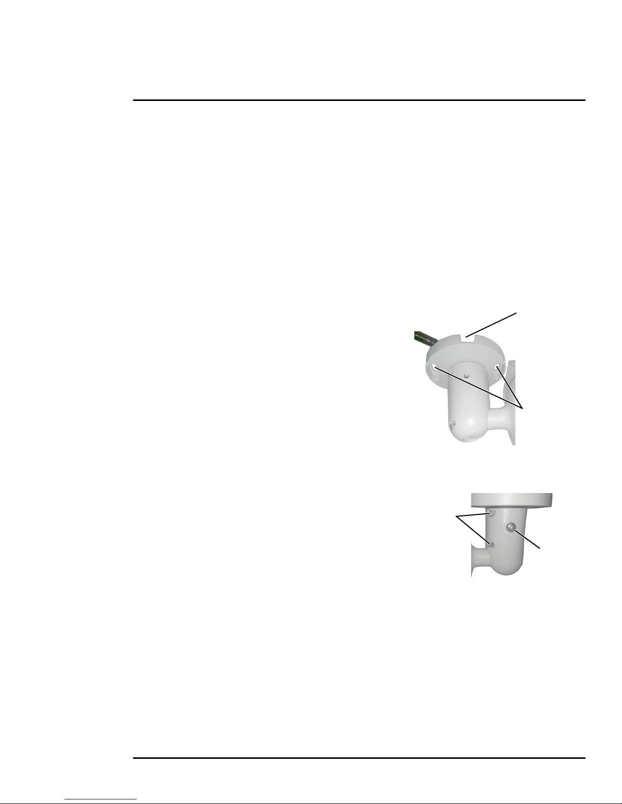
1 Camera Installation
M4 mounting
slots
Slot for surface
mounting
cable
Ball-joint
set screws
Base
set screw
1.4.4 Alarm Connections—Not supported
1.4.5 Ethernet
Connect a shielded Cat5e or Cat6 Ethernet cable to the RJ-45 jack. If using PoE to supply power to
the camera, connect the other end of the cable to a PoE switch or PoE injector. Otherwise connect
the cable to a network switch.
1.4.6 Camera Grounding
Ensure the camera is properly grounded. Failure to properly ground the camera can lead to
permanent damage to the camera. Typical to good grounding practices, the camera chassis ground
should be connected to the lowest resistance path possible.
1.5 Mounting the Camera
1. Place the supplied template where you will install the
camera. Mark the position of the two screw holes for the
base of the mounting bracket.
2. At the center of the template, a cable entry hole 40 mm
(1.57”) in diameter will provide for hidden cables.
3. Drill the cable entry hole for cables or use the slot for
surface mounting the cables.
4. Drill holes slightly smaller than the supplied plastic screw
anchor on each marked screw hole.
5. Insert the plastic screw anchors into the drilled holes.
6. Connect the camera cables and thread them through the
cable entry hole. Refer to
7. Match the mounting slots of the camera with the plastic screw anchors at the installation location.
8. Fasten the camera with the supplied M4 screws.
9. Loosen the set screws in order to manipulate the
camera positioning at the ball joint. The camera can be
rotated, twisted, and pointed up or down at the ball joint.
10. Point the camera in the desired direction and fasten the
screws.
Camera Connections, pg. 9 for cable connections.
427-0064-00-12 Version 100 August 2017 11
Page 12

1 Camera Installation
1.6 Camera specifications
Camera Model FB-Series O
Camera Platform Type Fixed
Composite Video NTSC or PAL—switchable from the web page.
Thermal Camera
Array Format 324 x 256 (17 µm pixel pitch)
Detector Type Long-Life, Uncooled VOx Microbolometer
Effective Resolution 76,800
Field Of View (Focal Length) for
available 324 x 256 camera lens
configurations.
Spectral Range 8 µm to 14 µm
Lens Athermalized, focus-free
Ge n e r a l
Weight 2.3 lb (1 kg) with sun shield
Dimensions (L,W,H) 11.1" x 3.8" x 3.7" (285 mm x 96 mm x 94 mm)
Input Voltage dc 12 Vdc (±10 %)
Input Voltage ac 24 Vac (±10 %)
Input Voltage PoE IEEE 802.3af-2003 standard
Power Consumption 17 W at 12 Vdc maximum with heaters
Mounting Provisions One 1/4-20” threaded holes on bottom.
Shipping weight 3.85 lbs (1.75 kg)
Shipping Dimensions 14.375”(L) x 7.375”(W) x 7”(H)
Environmental
IP rating (dust and water ingress) IP66
Operating temperature range -40 °C to 50 °C (-40 °F to 122 °F) cold start
Storage Temperature range -20 °C to 70 °C (-4 °F to 158 °F)
Humidity 0-90% relative
Approvals FCC Part 15 (Subpart B, Class A), CE mark, EN55032,
Refer to Select Video format, pg. 29.
FB-324-O = 24° × 19° (12.8 mm)—17 µm pixel pitch
FB-349-O = 49° × 37° (6.8 mm)—17 µm pixel pitch
FB-393-O = 93° × 70° (3.7 mm)—17 µm pixel pitch
with sun shield and fully extended mounting arm
13 VA at 24 Vac maximum with heaters
Two M4 hole slots on mounting arm.
EN55024, RoHS, WEEE
427-0064-00-12 Version 100 August 2017 12
Page 13

2 Basic Operation and Configuration
A bench test can be used to verify camera operation before the camera is configured for the local
network. This chapter also provides basic configuration information.
The camera has an Ethernet connection that allows streaming video over an IP network as well as
configuration and control of the camera
1
. It is possible to stream video and control the camera as it is
from the factory, without making any configuration changes. However in most cases the camera will
have at least some configuration changes to allow it to connect with other devices or other video
management systems on the existing network.
Once the camera is connected to a network and powered on, set camera network parameters using
the FLIR Discovery Network Assistant (DNA) software, perform a bench test by using a web browser
to view the video and control the camera, or view video in the local Network Video Management
System (for example, FLIR Latitude
free download from the
http://www.flir.com/security/display/?id=73533 web page and does not require
TM
). The FLIR Discovery Network Assistant (DNA) software is a
2
a license to use.
Getting the camera IP interface set up and working may requires familiarity with managing IP
networks. Prior to configuring the IP interface and streaming video parameters, be familiar with how to
manage and configure the other equipment in the network (for example, any PC or device that will
connect to the camera, any router or firewall that will carry the IP traffic, and so on).
2.1 IP Camera, ONVIF Profile S Compliant
When the camera is connected to the network it functions as a server; it provides services such as
camera control, video streaming, network communications, and geo-referencing capabilities. The
communications protocol used is an open, standards-based protocol that allows the server to
communicate with a video management client, such as FLIR Latitude or with a third-party VMS client,
including systems that are compatible with ONVIF Profile S.
There are two main components to the server software. One is a web server known as the web tool or
web interface that listens on the network for web browser requests, and is used for the initial (and
perhaps ongoing or occasional) configuration changes to the server. The web tool also allows the user
to view video and to operate the camera.
The other process, known as the Nexus Server, listens on the network for connections from clients
such as FLIR Latitude, ONVIF-compliant systems, or other VMS clients. These clients can be used to
control the camera and stream video during day-to-day operations of the camera.
1. For this chapter, it is assumed the camera will be connected to a network via Ethernet. For installations that use only analog video output, it is not possible to make configuration changes unless an
Ethernet connection is also used.
2. The web interface is supported on the latest versions of Microsoft Internet Explorer, Google Chrome,
and Mozilla Firefox.
427-0064-00-12, Version 100 August 2017 13
Page 14

2 Basic Operation and Configuration
Online manual
Select a filter
Select Assign IP
Right-click
2.2 Set IP Address using the FLIR Discovery Network Assistant (DNA)
The FB-Series O camera is shipped with a static IP address of 192.168.0.250. Assuming the existing
network uses IP addresses that are unique and different than the default address, configuring the
camera for IP communications generally involves the following steps:
Step 1 Connect the Ethernet port of the camera to the existing IP camera network.
Step 2 Connect a PC or laptop to the same network.
Step 3 From the PC connected to the camera network, use the DNA utility to discover and display
the camera’s current IP address.
a Download the DNA utility (2.1.3.15 or later) from the FLIR Firmware & Software
Downloads page at:
b Unzip the utility, then double-click to run the executable file ( DNA.exe). All the units on
the VLAN are discovered.
c For additional instructions on using DNA, refer to the DNA User’s Manual available in the
Help (
) link while the software is running.
http://www.flir.com/security/display/?id=73533.
Step 4 Right-click on the camera, select Assign
IP to change the IP address from the
default (192.168.0.250) to a another static
IP or select DHCP if a DHCP server is
used on the network.
Step 5 Double-click the camera in DNA’s
Discovery List to open the camera’s
web server Login page in Internet
Explorer or point your web browser to the
camera’s IP address.
Step 6 Enter the default user name (admin) and password (admin) to open the Live Video page.
Refer to
427-0064-00-12 Version 100 August 2017 14
Live Video Page, pg. 16.
Page 15

2 Basic Operation and Configuration
Figure 2-1: Camera Web Page Login Screen
2.3 Camera Bench Test
The camera offers both analog video and IP video, and since the camera can be powered by PoE or
by a conventional power supply, there are several ways to bench test the camera. It is recommended
that the installer test the camera using the same type of connections as in the final installation.
Even if using analog video and conventional power in the final installation, it is a good idea to test the
IP communications when performing the bench test. If any image adjustments are necessary, they
can be done using a web browser over the IP connection, and saved as power-on default settings.
Note
About 20 seconds after the camera is powered on, analog video starts and the camera’s IP address
is shown on the display for about 30 seconds.
With the camera powered up, analog video can be tested at the BNC connector. Connect the camera
to a video monitor and confirm the live video is displayed on the monitor.
If using a conventional power supply, connect the camera to a network switch with an Ethernet cable,
and connect a PC or laptop to the switch also. Use a web browser to access and test the camera as
described below, and if necessary make configuration changes prior to installation.
2.3.1 Log in to the Camera Web Page
With a web browser, log in to the camera using one of three User Names: user, expert, and admin.
By default, the passwords are: user, expert, and admin, respectively. The login passwords should
be changed to prevent unauthorized access (refer to
Basic Camera Configuration, pg. 18).
Open a web browser and enter the camera’s IP address. The login screen with a picture of the
camera will appear. A pull-down list in the upper right allows the user to select a language option.
Enter user for the User Name and user for the Password, and click Log in.
427-0064-00-12 Version 100 August 2017 15
Page 16
2 Basic Operation and Configuration
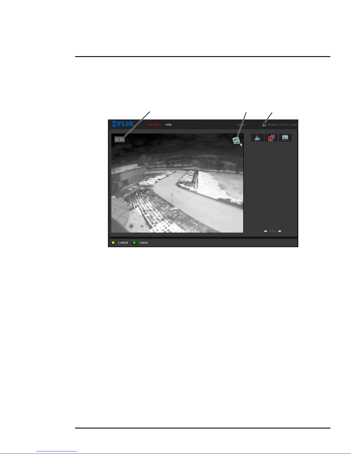
Figure 2-2: Live Video Web Page
Snapshot Toggle TimeVideo Source
2.3.2 Live Video Page
The Live Video page displays a live image from the camera on the left part of the screen and at the
top of the screen menu choices: including Live Video (the red text indicates it is selected), Help, and
Log out. The expert and admin logins provide additional menu choices.
In the lower right of the web page there is a frame rate selector. This selector allows the user to
change the rate at which the frames are displayed in the browser. This rate controls the user’s own
web browser only, and does not affect the video streams to other users or to an NVR. For slow
communication links, if there is a problem displaying the video image, it may help to slow down the
frame rate.
Help
The Help menu displays software version information. If it is necessary to contact FLIR Technical
Support for assistance, it will be helpful to have the information from this page on hand. For
information about the camera including hardware part numbers and serial numbers refer to
Product
Info Menu, pg. 34 (requires Admin login).
Log out
Use this button to disconnect from the camera and stop the display of the video stream. If a web
session is inactive for 20 minutes, it will be stopped and it will be necessary to log in again.
Toggle PC/Camera time
Use this button to display either the PC time or the camera time. To set the camera time refer to Date
and Time, pg. 20.
427-0064-00-12 Version 100 August 2017 16
Page 17
2 Basic Operation and Configuration
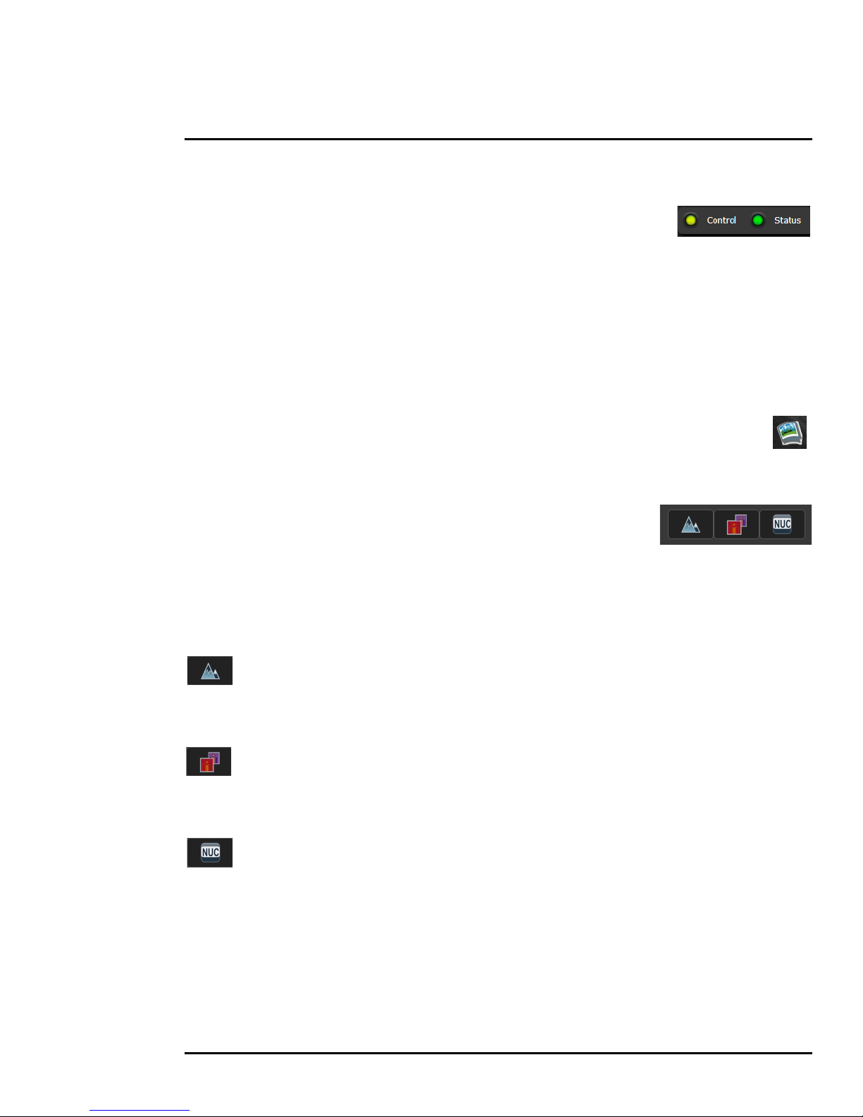
Camera Control and Status
In the lower left of the screen are two indicator “lights”: Control and Status.
Initially the Control light is off, as in the image above, indicating the user is not
able to control the camera immediately. When multiple users are connected to
a camera, only one user at a time can issue commands to the camera. If
another user has control of the camera, the Control light is yellow.
A user is able to request control of the camera by clicking on the yellow or black “light”, or simply by
sending a command to the camera. The Status light may turn off temporarily while waiting for the
response from the camera. After a short pause, the Control light should turn green.
If a command is sent to the camera when the user does not have control, the command will not be
executed, and it is necessary to send the command again once the light is green.
In addition, when the cursor is moved over the video, a snapshot button also appears in the
upper right of the screen. After clicking the snapshot button, the video image is saved as a
jpeg file and the browser will provide prompts depending on which browser is being used.
Web Control Panel
The control buttons on the right side of the page provide a way to control
the camera in a limited number of ways. When the mouse cursor is
positioned over a button, a tool tip is displayed.
This same web interface is used with various FLIR cameras—some are
fixed, such as the FB-Series
O cameras, and some are pan/tilt cameras.
The control panel may appear different for different FLIR cameras.
The following buttons appear for the FB-Series O cameras:
Toggle Polarity
This button changes the polarity of the assigned colors to the different temperatures in a
scene. In the black and white palette for example, hot objects are displayed as white and cold objects
as black, or vice versa.
Toggle Palette
This button causes the camera to cycle through six different look up table (LUT) color
palettes. Depending on the subjects viewed, one color palette may be preferable to the others. The
Toggle Polarity button allows access to six more palettes (refer to
Misc. (Lookup Table), pg. 30).
Perform IR NUC Calibration
This button causes the camera to perform a Non-Uniformity Correction operation (refer to
Image freezes momentarily, pg. 24).
427-0064-00-12 Version 100 August 2017 17
Page 18

2 Basic Operation and Configuration
2.4 Basic Camera Configuration
The following procedures describe how to do the most common bench test camera configuration
steps, such as setting the camera IP address and hostname and changing the user password. To
make these changes, it is necessary to login using the expert user account. Additional setup and
configuration options required after the camera has been installed in its final location are described
after the basic steps are given, refer to
2.4.1 Setup Menu
The Setup menu is used for GEO Settings (Latitude and Longitude location), Video setup, and
thermal (IR) camera setup. For additional details, refer to
Adjustments to the IR settings should only be made by someone who has expertise with thermal
cameras and a thorough understanding of how the various settings affect the image. In most
installations, the only camera settings needed are available from the Web Control panel on the Live
Video page (Palettes and Polarity). Haphazard changes can lead to image problems including a
complete loss of video. Additional information is provided in
Advanced Configuration, pg. 27.
Setup Menu, pg. 27.
Thermal Image Setup, pg. 29.
When making configuration changes using the Setup page, most of the changes take effect
immediately, and it is not necessary to start and stop the server. However it is necessary to save the
changes (with the Save Settings button at the bottom of the page) if it is desirable to use the new
settings as a default when the camera is powered on.
When a user logs in as admin, a complete Maintenance menu is available (refer to Maintenance
Menu, pg. 31). The Maintenance menu also provides access to other configuration options. For
more information on setting or changing other camera parameters refer to the Nexus IP Camera
Configuration Guide (FLIR Doc #427-0030-00-28).
2.4.2 Server Menu
When a user logs in as expert or admin, the Maintenance Server menus are
available. When the Server menu is selected, the LAN Settings page appears.
The basic camera configuration steps are accessed through the Maintenance
Server menu, using the menus on the left side of the page. The LAN Settings,
Services, and Security Options selections are described below. The expert
login has access to these Server pages, but will only see the security settings
for the user login.
With most configuration changes through the Maintenance menu, it is
necessary to save the changes, then stop and restart the server to make the
changes take effect.
427-0064-00-12 Version 100 August 2017 18
Page 19
2 Basic Operation and Configuration
Scroll down
to Save
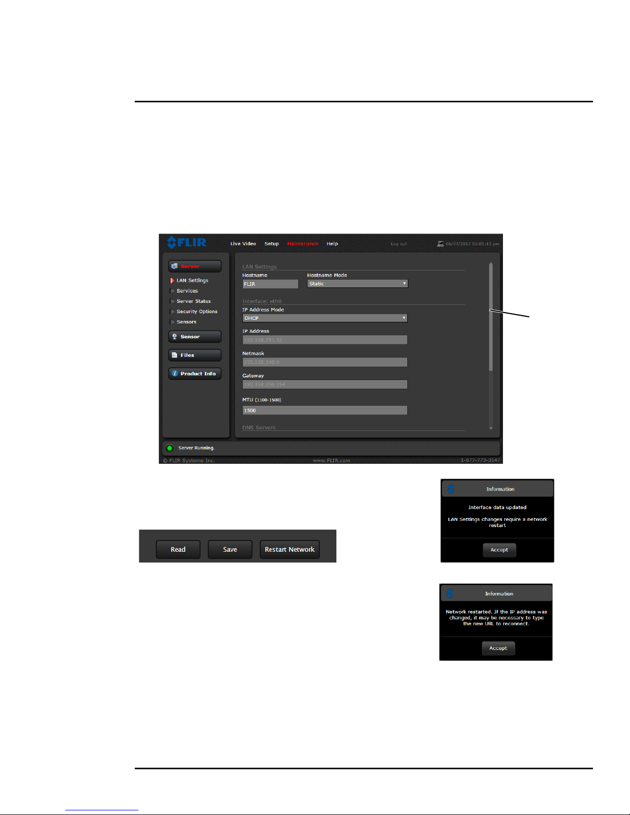
LAN Settings: The LAN Settings page can be used to set the hostname, default gateway, and IP
address for the camera. Scroll down to see settings for Domain Name System (DNS) server.
IP Address
The default IP Address mode is set to Static; the mode can also be set to DHCP addressing if a
DHCP server is used by the network. To set the IP address using DNA, refer to
the FLIR Discovery Network Assistant (DNA), pg. 14.
Set IP Address using
When the IP address is changed and the
Save button is clicked, a pop-up message
will appear to indicate the network interface
must be restarted.
Once the IP address of the camera is
changed, the PC may no longer be on the
same network and therefore may not be able
to access the camera until the IP address on
the PC is changed also.
427-0064-00-12 Version 100 August 2017 19
Page 20
2 Basic Operation and Configuration
Toggle Server (Stop/Start)
Services Menu
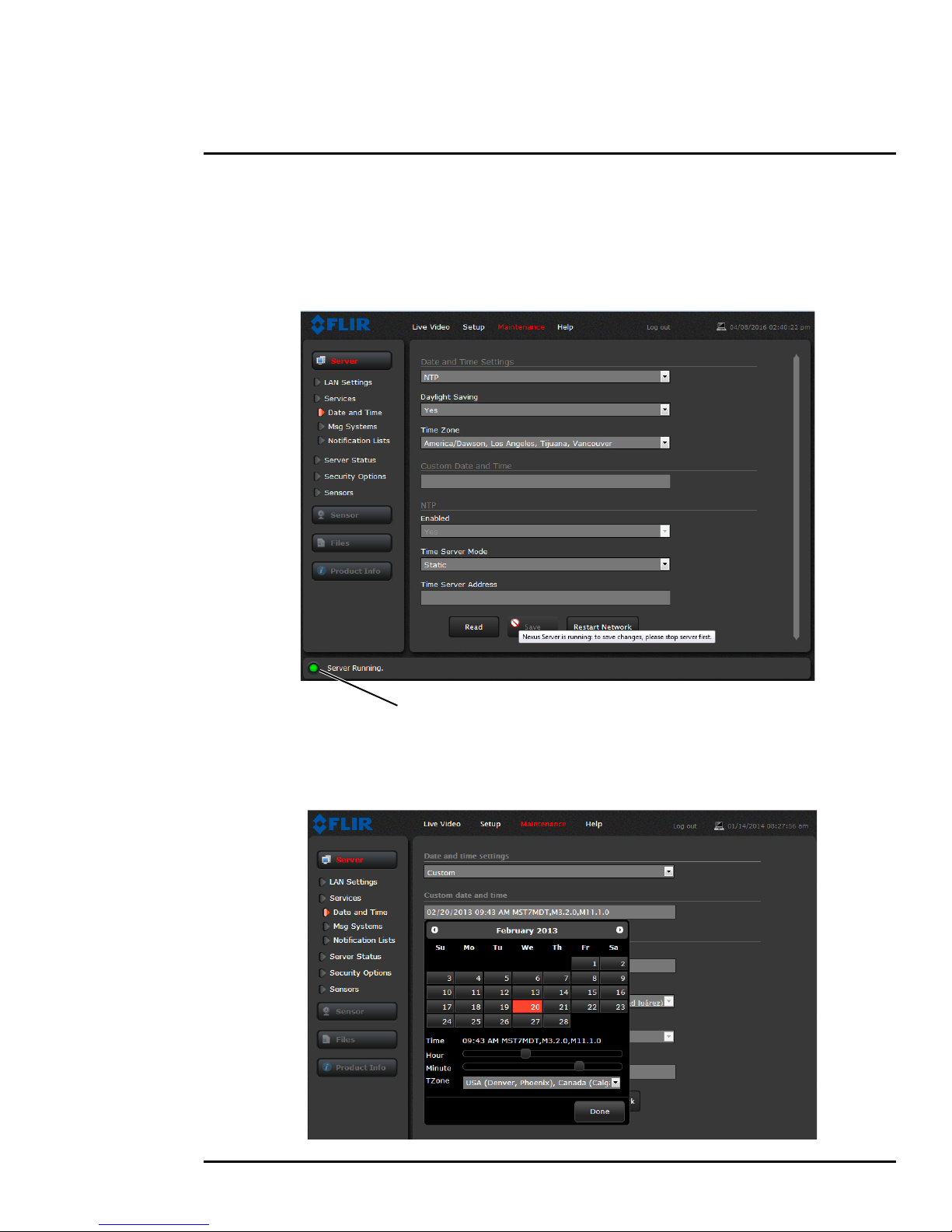
Date and Time: The Date and Time settings page is used to configure the date and time settings.
The date, time, and time zone can be obtained from an NTP server, or can be entered manually. If
NTP mode is selected, the NTP server information can be entered. The Nexus server must be
stopped before changes can be saved.
Set the date and time parameters, then select the Save button at the bottom of the page. After saving
the settings, reboot the system. Refer to
Server Status, pg. 21.
If the Custom mode is selected, a pop-up window allows the information to be entered manually.
427-0064-00-12 Version 100 August 2017 20
Page 21
2 Basic Operation and Configuration
Toggle Server (Stop/Start)
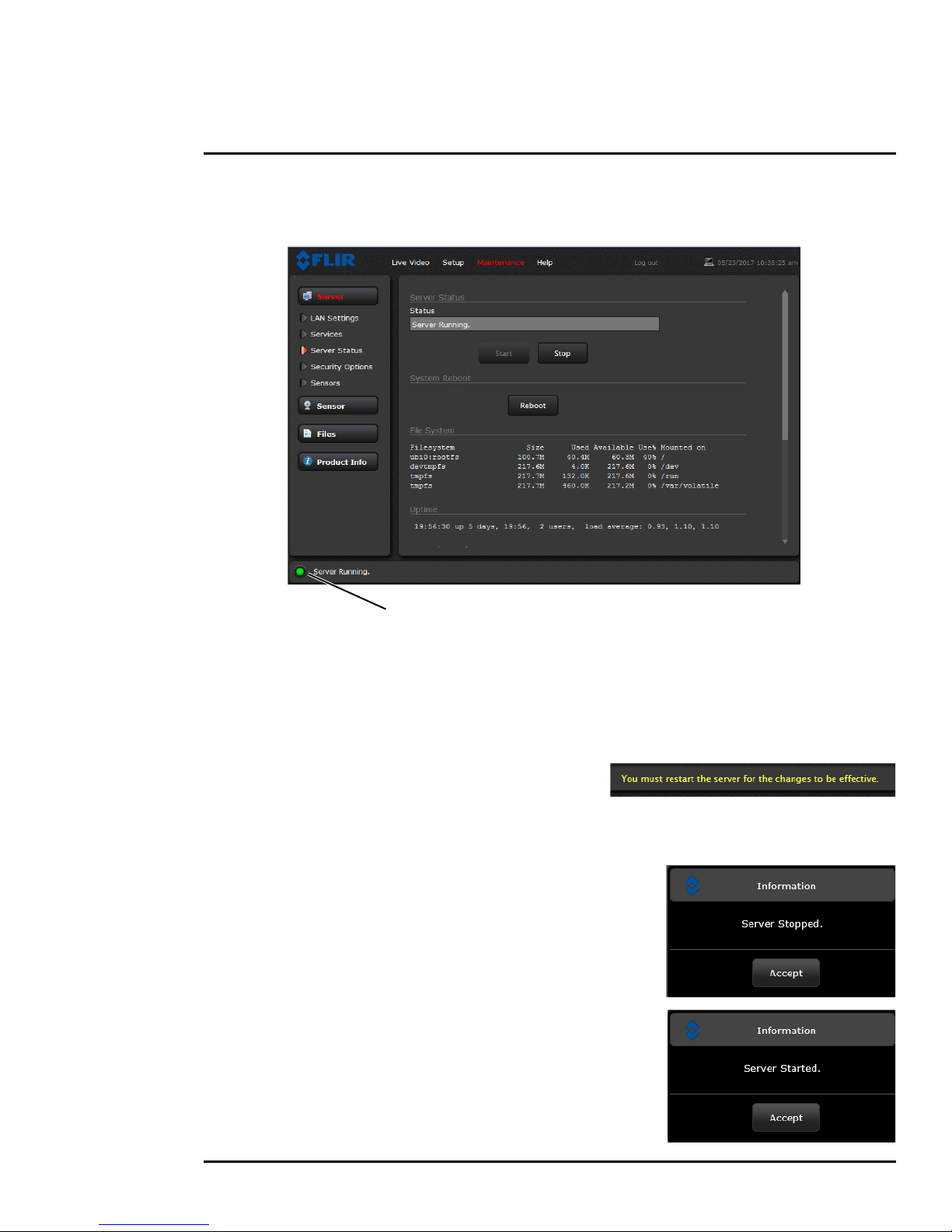
Server Status: The Server Status page provides an indication of the current server status (either
running or stopped) and buttons for starting or stopping the server or for rebooting the system.
After making configuration changes, it is necessary to save the changes to the server (there is a
Save button at the bottom of each configuration page). The configuration changes do not take effect
immediately. Generally, it is also necessary to stop and restart the server for the changes to become
effective. The server has a configuration that is active and running, and another configuration that is
saved (and possibly different than the running configuration).
The message at the bottom of the page indicates the
saved configuration is different than the active (running)
configuration, and it is necessary to restart the server.
It may take up to 20 seconds or more to stop the server, especially when there are multiple video
streams open. Be patient when stopping the server.
When the server is stopped and the page is refreshed, the
status will show Server Stopped and the Start button will
be enabled.
Click on the Start button to restart the server, and when the
page refreshes, the status will again show Server Running.
The Start button will be replaced by a Stop button when
the startup procedure has completed.
427-0064-00-12 Version 100 August 2017 21
Page 22
2 Basic Operation and Configuration
Add IP
address
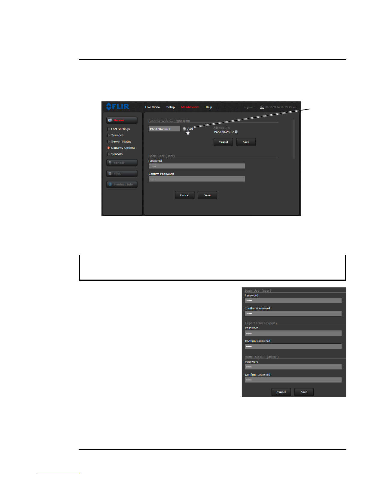
Security Options: Use the Security Options page to restrict access through the camera web
server to specific IP addresses and to set or change passwords. As shown below, the expert login
can only configure the user login password.
As an additional security measure, limit which computers have access to the web browser interface.
Simply add a computer’s IP address and click Add. After all the allowed IP addresses are entered,
select the Save button to save the changes.
Note
A VMS Remote to the camera, ONVIF or Nexus CGI, uses the same password as the web interface.
Changing the password in either interface changes the password in both.
Refer to VMS Remote, pg. 32.
To maintain security of the system set new passwords for
each of the three login accounts (requires the admin login).
• user—The user account can only use the Live Video
page and controls.
• expert—The expert account can use the Live Video
page, the camera Setup page, and the Server pages
on the Maintenance menu.
• admin—The admin account can use all pages.
After a password is set and confirmed, select the Save
button at the bottom (scroll down the page, if necessary).
427-0064-00-12 Version 100 August 2017 22
Page 23
2 Basic Operation and Configuration
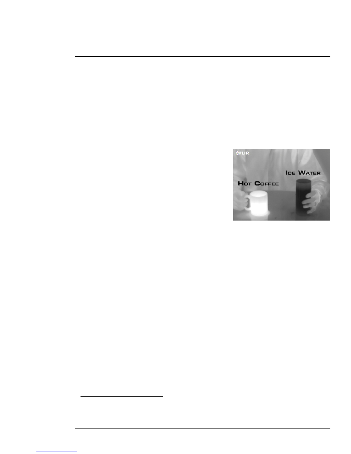
2.5 Thermal Imaging Overview
The thermal camera makes an image based on temperature differences. In the thermal image, by
default the hottest item in the scene appears as white and the coldest item is black, and all other
items are represented as a gray scale value between white and black.
Both thermal and daylight cameras have detectors (pixels) that detect energy. One difference
between thermal and daylight cameras has to do with where the energy comes from to create an
image. When viewing an image with a daylight camera, there has to be a source of visible light
(something hot, such as the sun or lights) that reflects light off the objects in the scene. The same is
true with human eyesight; the vast majority of what people see is based on reflected light.
The thermal camera, on the other hand, detects energy that
is directly radiated from objects in the scene. Most objects
in typical surroundings are not hot enough to radiate visible
light, but they easily radiate energy in the portion of the
infrared spectrum that the camera can detect, the long wave
infrared (LWIR). Even very cold objects, like ice and snow,
radiate this type of energy.
This is why hot objects such as parts on an engines and
exhaust pipes appear white, while the sky, puddles of water
and other cold objects appear dark (or cool)
3
. Scenes with
familiar objects will be easy to interpret with some
experience. The camera automatically optimizes the image to provide the best contrast in most
conditions, and in some cases other settings can be used to further improve the image.
The performance of the camera will likely vary throughout the day. After sunset, objects warmed by
the sun will appear warmest. Early in the morning, many of these objects will appear cooler than their
surroundings, so be sure to look for subtle differences in the scene, as opposed to just hot targets.
2.6 Maintenance and Troubleshooting Tips
If help is needed during the installation process, contact the local FLIR representative, or call the
appropriate support number listed at: http://www.flir.com/security/display/?id=71083. FLIR Systems,
Inc. offers a comprehensive selection of training courses to help get the best performance and value
from the thermal imaging camera. Find out more at the FLIR training web page:
training.
Cleaning
Great care should be used with your camera's optics. They are delicate and can be damaged by
improper cleaning. The FB-Series
O thermal camera lenses and windows are designed for a harsh
outdoor environment and have a coating for durability and anti-reflection, but may require cleaning
occasionally. FLIR Systems, Inc. suggests that you clean the lens when image quality degradation is
noticed or excessive contaminant build-up is seen on the lens.
http://www.flir.com/
3. By default, the camera represents hot objects as white and cold objects as black. The camera can
be set to use the Black Hot polarity setting, which displays hot objects as black and cold objects as
white and is effectively the negative of White Hot polarity. Refer to
427-0064-00-12 Version 100 August 2017 23
Toggle Polarity, pg. 17.
Page 24

2 Basic Operation and Configuration
Rinse the camera housing and optics with low pressure fresh water to remove any salt deposits and
to keep it clean. If the front window of the camera gets water spots, wipe it with a clean soft cotton
cloth dampened with fresh water.
Do not use abrasive materials, such as paper or scrub brushes as this will possibly damage the lens
by scratching it. Only wipe the lens clean when you can visually see contamination on the surface.
Use the following procedure and solvents, as required:
• Acetone – removal of grease
• Ethanol – removal of fingerprints and other contaminants
• Alcohol – final cleaning (before use)
Step 1 Immerse lens tissue (optical grade) in Alcohol, Acetone, or Ethanol (reagent grade).
Step 2 With a new tissue each time, wipe the lens in an “S” motion
(so that each area of the lens will not be wiped more than once).
Step 3 Repeat until the lens is clean. Use a new tissue each time.
Image freezes momentarily
By design, the camera image freezes momentarily on a periodic basis during the Flat Field Correction
(FFC) cycle (also known as Non-Uniformity Correction or NUC). Every so often, the image will
momentarily freeze for a fraction of a second while the camera performs a flat field correction. A
shutter activates inside the camera and provides a target of uniform temperature, allowing the
camera to correct for ambient temperature changes and provide the best possible image.
No video
If the camera will not produce an image, check the video connection at the camera and at the display.
If the connectors appear to be properly connected but the camera still does not produce an image,
ensure that power has been properly applied to the camera and the circuit breaker is set properly. If a
fuse was used, be sure the fuse is not blown. If the video cabling is suspected as a possible source of
the problem, plug a monitor into the BNC connection inside the camera and determine if it produces
an image.
When the camera is powered on, it will do a NUC operation shortly after startup. If it is uncertain if the
camera is receiving power, it may be useful to listen to the camera to hear if the click-click of the
shutter mechanism can be heard. It may only be possible to perform this test when the camera is on
a work bench rather than in its installed position.
If the camera still does not produce an image, contact the FLIR dealer or reseller who provided the
camera, or contact FLIR directly.
Performance varies with time of day
There may be differences in the way the camera performs at different times of the day, due to the
diurnal cycle of the sun. Recall that the camera produces an image based on temperature
differences.
At certain times of the day, such as just before dawn, the objects in the image scene may all be
roughly the same temperature. Compare this to imagery right after sunset, when objects in the image
427-0064-00-12 Version 100 August 2017 24
Page 25

2 Basic Operation and Configuration
may be radiating heat energy that has been absorbed during the day due to solar loading. Greater
temperature differences in the scene will allow the camera to produce high-contrast imagery.
Performance may also be affected when objects in the scene are wet rather than dry, such as on a
foggy day or in the early morning when everything may be coated with dew. Under these conditions,
it may be difficult for the camera to show the temperature of the object itself, rather than of the water
coating.
Unable to View Video Stream
If the video stream from the camera is not displayed, it could be that the packets are blocked by the
firewall, or there could be a conflict with video codecs that are installed for other video programs.
When displaying video with FLIR Latitude or a VMS for the first time, the Windows Personal Firewall
may ask for permission to allow the video player to communicate on the network. Select the check
boxes (domain/private/public) that are appropriate for the network.
If necessary, test to make sure the video from the camera can be viewed by a generic video player
such as VLC media player (http://www.videolan.org/vlc/). To view the video stream, specify RTSP
port 554 and the appropriate stream name. For example:
rtsp://192.168.0.250:554/stream1/sensor1, and
rtsp://192.168.0.250:554/stream2/sensor1
Port 554 is the standard RTSP port as well as the default for the camera. Typically, if the default port
has not been changed, the port can be left out of the streaming command, such as:
rtsp://192.168.0.250/stream1/sensor1.
In addition, to maintain compatibility with legacy systems the stream names are aliased as:
ch0 = stream1/sensor1 and ch1 = stream2/sensor1.
The video streams can be accessed with the shortened strings, such as rtsp://192.168.0.250/ch0.
Refer to Video, pg. 28 for additional information on RTP settings and stream names.
Unable to control the camera
If the camera does not respond to commands, the user may not have control of the camera. The web
server allows two sessions to be connected to the camera at a time. By default, control of the camera
will automatically be requested.
Verify the camera IP address
To verify the camera IP address, cycle power to the camera while watching the analog video. About
20 seconds after the camera is powered on, analog video starts and the camera’s IP address is
shown on the display for about 30 seconds.
Noisy image
With the analog video signal, a noisy image is usually attributed to a cable problem (too long or
inferior quality) or the cable is picking up electromagnetic interference (EMI) from another device.
Although coax cable has built-in losses, the longer the cable is (or the smaller the wire gauge/
thickness), the more severe the losses become; and the higher the signal frequency, the more
pronounced the losses. Unfortunately this is one of the most common and unnecessary problems
that plagues video systems in general.
427-0064-00-12 Version 100 August 2017 25
Page 26

2 Basic Operation and Configuration
Figure 2-3: Images facing sun from standard camera (left)
and thermal camera (right)
Cable characteristics are determined by a number of factors (core material, dielectric material, and
shield construction, among others) and must be carefully matched to the specific application.
Moreover, the transmission characteristics of the cable will be influenced by the physical environment
through which the cable is run and the method of installation. Use only high quality cable and ensure
the cable is suitable to the environment.
Check cable connector terminations. Inferior quality connections may use multiple adapters which
can cause unacceptable noise. Use a high-quality video distribution amplifier when splitting the signal
to multiple monitors.
Image too dark or too light
By default the FB-Series O camera uses an Automatic Gain Control (AGC) setting that has proven to
be superior for most applications, and the camera will respond to varying conditions automatically.
The installer should keep in mind that the sky is quite cold and can strongly affect the overall image.
It may be possible to avoid a problem by slightly moving the camera up or down to include (or
exclude) items with hot or cold temperatures that influence the overall image. For example, a very
cold background (such as the sky) could cause the camera to use a wider temperature range than
appropriate.
Eastern or Western Exposure
Once installed, the camera may point directly east or west, and this may cause the sun to be in the
field of view during certain portions of the day. We do not recommend intentionally viewing the sun,
but looking at the sun will not permanently damage the sensor. In fact the thermal imaging camera
often provides a considerable advantage over a conventional camera in this type of back-lit situation.
However, the sun may introduce image artifacts that will eventually correct out and it may take some
time for the camera to recover. The amount of time needed for recovery will depend on how long the
camera was exposed to the sun. The longer the exposure, the longer the recovery time needed.
427-0064-00-12 Version 100 August 2017 26
Page 27

3 Advanced Configuration
Camera Control
In this chapter, additional setup and configuration settings related to the following topics are described:
• Setting up the video streams to optimize quality and network performance
• Selecting NTSC or PAL analog video format
• Optimizing the thermal image
• Configuring the camera to work with a third-party VMS (ONVIF)
When configuration changes are made with the web browser, the settings are saved to a configuration
file. It is a good idea to make a backup of the existing configuration file prior to making changes, and
another backup once the changes are finalized. If necessary the camera can be restored to its original
factory configuration or one of the saved configurations (refer to
3.1 Setup Menu
It is necessary to have control of the camera to make Setup changes. Changes made through the
Setup menu have an immediate effect (it is not necessary to stop and restart the server). To use these
settings at power up, it is necessary to save the changes (
Files Menu, pg. 33).
Save Settings, pg. 30).
427-0064-00-12, Version 100 August 2017 27
Page 28

3 Advanced Configuration
3.1.1 Video Setup
Video: By default, two video streams are enabled for the camera: Video 0 and Video 1. Both video
streams are available for viewing from a client program such as FLIR Latitude, a stand-alone video
player, or a third-party VMS (including ONVIF systems). To modify parameters that affect a particular
IP Video stream from the camera, select the appropriate link (for example, Video - 0).
With the factory configuration, the default parameters
provide high-quality full frame-rate video streams with
reasonable bandwidth usage. In general, for most
installations it will not be necessary to modify the default
parameters. However in some cases, such as when a video
stream is sent over a wireless network, it may be useful to
“tune” the video stream to try to reduce the bandwidth
requirements. The Encoding parameters are described
below.
After making adjustments, scroll down to save the changes
through power cycles.
The parameters in the Encoding section will have a significant impact on the quality and bandwidth
requirements of the video stream. Use the default values initially, and then individual parameters can
be modified and tested incrementally to determine when bandwidth and quality requirements are met.
For the video streams, the Codec options are H.264 or MJPEG.
The Bit Rate parameter is only used when the Rate Control parameter is set to CBR (Constant Bit
Rate). With the CBR setting, the system attempts to keep the video at or near the target bit rate.
With Rate Control set to VBR (Variable Bit Rate) the Bit Rate parameter is replaced with a Quality
parameter.
The I-Frame Interval parameter controls the number of P-frames used between I-frames. I-frames
are full frames of video and the P-frames contain the changes that occurred since the last I-frame. A
smaller I-Frame Interval results in higher bandwidth (more full frames sent) and better video quality. A
higher I-Frame Interval number means fewer I-frames are sent and therefore results in possibly lower
bandwidth and possibly lower quality.
427-0064-00-12 Version 100 August 2017 28
Page 29

3 Advanced Configuration
Select video format
Save
The video streaming is done using a protocol generally
referred to as Real-time Transport Protocol (RTP), but there
are actually many protocols involved, including Real-Time
Transport Control Protocol (RTCP) and Real Time Streaming
Protocol (RTSP). The default value for the stream from
VIDEO - 0 is stream1/sensor1.
The complete connection strings are:
rtsp://192.168.0.250:554/stream1/sensor1 for VIDEO - 0 and
rtsp://192.168.0.250:554/stream2/sensor1 for VIDEO - 1. By
default the video stream uses the IP address of the camera.
Select Video format
The video format only applies to the video output on the
analog video BNC connector. Select either NTSC or PAL
depending on the video viewing and recording devices
connected to the camera. Select Save.
3.1.2 Thermal Image Setup
In most installations it will not be necessary to change the thermal camera from the default settings.
However in some situations, depending on weather, time of day and so on, it may be useful to make
changes to the video image to enhance the image by modifying one or more of the parameters.
However, be aware that when the conditions change the camera may need to be adjusted again; for
that reason it is a good idea to know how to restore the factory default settings as well.
IR Page
In the IR page, a single JPEG image (a snapshot) is displayed in the upper right-hand corner. To
update this image at any time, select the Refresh button in the upper right. The AGC region of
interest (ROI) can be selected from the pull-down list.
427-0064-00-12 Version 100 August 2017 29
Page 30

3 Advanced Configuration
To make adjustments to the thermal image, it is possible to modify the AGC ROI and AGC headings.
The overall image display (also known as Polarity or Color Palette) is determined by the Look Up
Table (LUT) selected in the Misc. (Lookup Table) section.
AGC ROI: The AGC ROI determines what
portion of the image is used in the calculation
of the AGC. It may be possible to improve
the contrast of the image if a portion of the
field of view is excluded. For example, if a
portion of the sky is included, typically quite
cold, it is desirable to restrict the ROI to the
portion of the image below the horizon.
When Custom is selected the region can be
moved by dragging or resized by grabbing
the lower right hand corner.
AGC: The AGC parameters control the overall
brightness and contrast, and determine how
the overall video image appears. The defaults
are suitable for most installations, but in some
cases different settings may provide a more
appealing image, depending on personal
preferences. Be aware the settings that are
optimal at one time may be less optimal a short time later, since conditions such as weather and time
of day affect the image and are constantly changing.
Experiment with different AGC parameters to find the settings that work best for the particular
installation. Select Save Settings button at the bottom of the page to keep the settings after a power
cycle or select the Factory Defaults button to return the settings to default values.
• Brightness (ITT Mean) determines the temperature that is at the middle of the 256 “shades of
gray” available to the camera. Higher values allow more detail in hotter scenes, while lower
values allow more detail in lower temperature scenes.
• Contrast (Max Gain) can generally be used to increase contrast, especially for scenes that have
little temperature variation (although it may also increase noise due to increased gain).
• Sharpness (DDE) is used to enhance image details and/or suppress fixed pattern noise. Higher
values increase Sharpness, while lower values soften the image and filter fixed pattern noise.
• AGC Filter determines how quickly a scene will adjust when a hot object appears (or disappears)
within the AGC region of interest. When AGC Filter is set to a low value, when a hot object enters
the region of interest, the AGC will adjust more slowly to the hot object, resulting in a more
gradual transition.
Misc. (Lookup Table): Each Look Up Table (LUT) provides a
different representation of the detected levels of thermal energy
as colors or gray-scale values. White hot and black hot are gray
scale palettes; other tables assign different colors to different
temperatures. These color palettes can be selected from the
Live Video page (refer to
Toggle Palette, pg. 17).
Save Settings: Click the Save Settings button to store the current settings as power up defaults. To
restore the original settings, select the Factory Defaults button and then click on Save Settings.
427-0064-00-12 Version 100 August 2017 30
Page 31

3 Advanced Configuration
3.2 Maintenance Menu
The following sections describe more advanced camera configuration options that require the admin
login. For the configuration changes in the remainder of this chapter, it is necessary to save the
changes, then stop and restart the server to make the changes effective. Additional configuration
options are available that are not described in this manual. For more information on setting or
changing these camera parameters refer to the Nexus IP Camera Configuration Guide (FLIR Doc
#427-0030-00-28) or contact the local FLIR representative or FLIR Technical Support.
The basic camera configuration settings (LAN Settings, Services, and Security Options) available
through the expert login are described in
Maintenance menus are accessible, including Sensor, Files and Product Info.
3.2.1 Sensor Menu
The configuration changes commonly used are done through the Sensor
menu. Described below are configuration steps from the Communications
and Modules selections.
Server Menu, pg. 18. When logged in as admin, additional
Communications Menu
The primary IP configuration parameters, such as IP address, network
mask, and gateway, are configured with the LAN Settings page (refer to
LAN Settings, pg. 19). The Networking page can be used to configure some
of the other IP networking parameters.
Networking Page: Generally it is assumed the camera network will be secured through recognized
network security measures and best practices, such as limited physical access, firewalls, and so on.
As an additional security consideration, it is possible to restrict access to the camera to a limited
number of IP Addresses.
The default TCP port for most FLIR IP cameras is 1001. This is the port number that a client program
such as FLIR Latitude can use to communicate with the camera. If using an ONVIF-compliant VMS
as a client, refer to VMS Remote, below.
427-0064-00-12 Version 100 August 2017 31
Page 32
3 Advanced Configuration
Set
Enter IP
Addresses
to No
pull-down
For ONVIF,
use the settings
in Interface 1
Scroll down
For Nexus CGI,
use the settings
in Interface 0
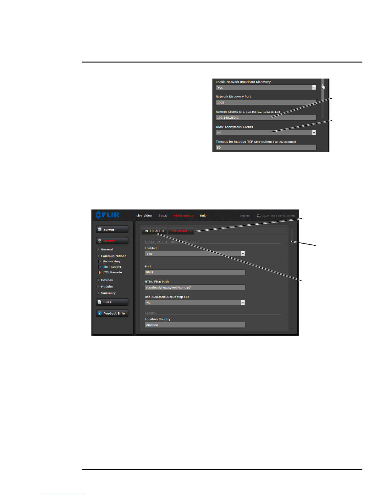
If the Enable Network Broadcast Discovery
parameter is set to Yes, the camera sends
out a “discovery” packet on the network every
half second as an Ethernet broadcast. To
restrict client programs to allowed IP
addresses, enter allowed IP addresses in the
Remote Clients list, then set the Allow
anonymous clients parameter to No, and
click Save. The changes will not take effect
until the server is stopped and started.
It is also possible to restrict access to the camera web server. Refer to Security Options, pg. 22 to add
allowed IP address to the list in the Restrict Web Configuration section.
VMS Remote: The VMS Remote page provides communication interfaces for devices that connect
to the camera. Authentication when enabled uses the same passwords set from the Server Security
Options page. Refer to
Security Options, pg. 22.
Nexus CGI Interface
After the interface is configured, scroll down and click on the Save button to save the configuration.
The changes will not take effect until the server is stopped and started.
ONVIF Interface
An ONVIF-compliant VMS can be used to control a FLIR camera. Refer to the VMS documentation to
determine what parameters are needed. By default, the camera is configured with a VMS Remote
interface with ONVIF 2.0 parameters (Profile S). After the interface is configured, scroll down and
click on the Save button to save the configuration. The changes will not take effect until the server is
stopped and started.
Several types of third-party Video Management Systems (VMS) are supported by FLIR IP cameras.
Because these systems tend to evolve and change over time, contact the local FLIR representative
or FLIR Technical Support to resolve any difficulties or questions about using this feature.
427-0064-00-12 Version 100 August 2017 32
Page 33
3 Advanced Configuration
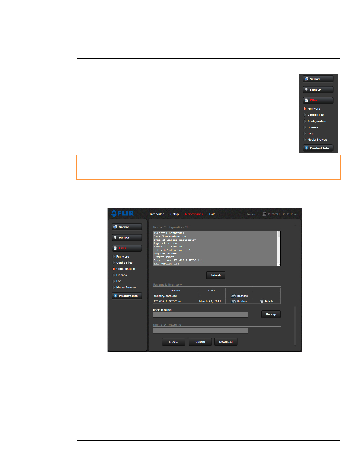
3.2.2 Files Menu
The administrative actions for accessing, updating, and
transferring files are accessed through the Files menu on the left
side of the page. Selected actions from the Firmware,
Configuration, and Log pages are described below.
For manual firmware updates, install the firmware update file by
first stopping the camera server, browsing to select the update file
on your computer, and then selecting Upload. The firmware files
will be uploaded and installed.
Caution!
The firmware update procedure resets the FB-Series O camera to default settings.
Before performing the update, detach the camera from any VMS.
A firmware update resets video settings, IR settings, and rules to factory defaults.
Use the Configuration page to view the Nexus Configuration File, perform Backup & Recovery of
local files (on the camera), and perform Upload & Download of configuration files to another
computer for backup, or to install a new configuration file to the camera.
Shown at the top of the screen is the configuration script file in a scrollable window. This can be
useful if help is ever need help from a support engineer.
In the Backup & Recovery section, click the Restore link associated with the factory.defaults
configuration to restore the camera to its factory settings. This file can not be modified or deleted, so
it is always available.
Use the Backup button to make a backup of the final settings. This will make a backup copy of the
configuration file and store it locally on the camera.
427-0064-00-12 Version 100 August 2017 33
Page 34
3 Advanced Configuration
Enter name
Click Update
In the Upload & Download section, the Download button can be used to save a copy to a PC for safe
keeping. A pop-up window will ask for a file name and destination folder.
The Upload button is used to transfer a configuration file from a PC to the camera.
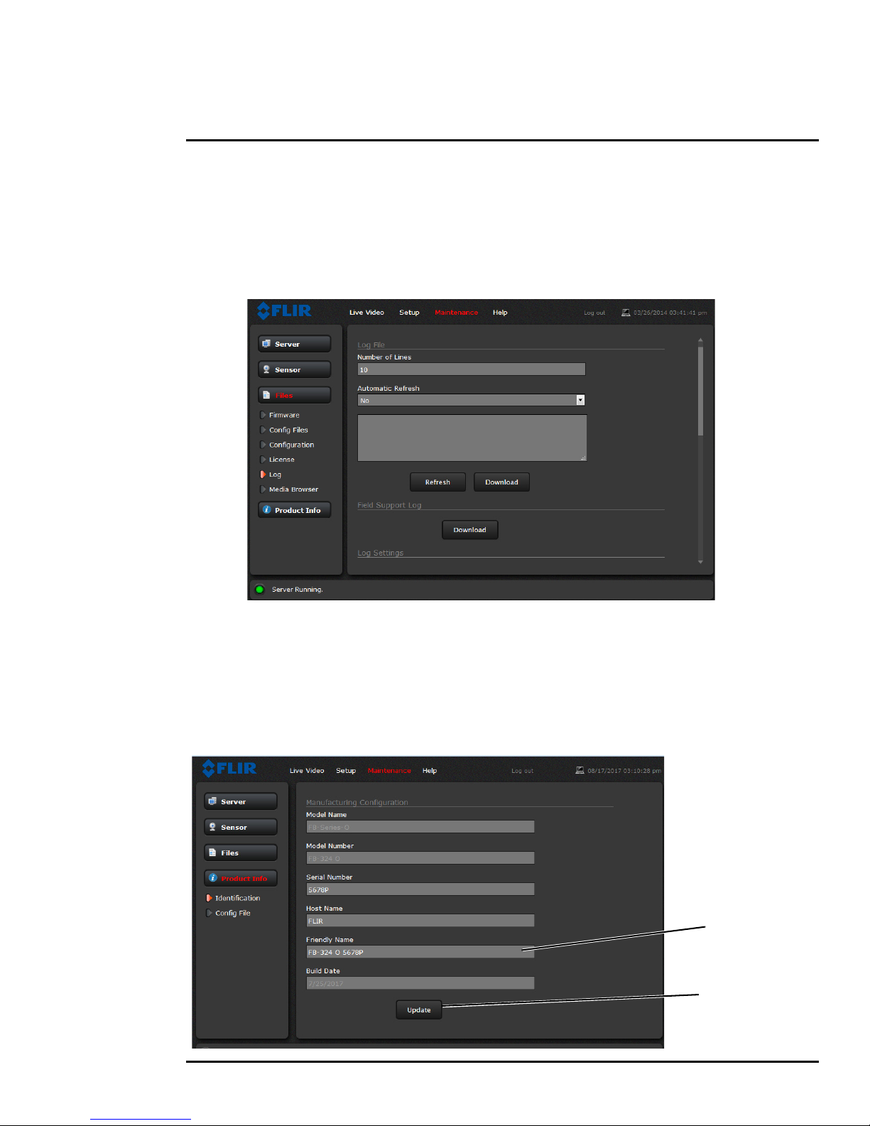
Use the Log page to set logging parameters. Scroll down and select the Download button under
Field Support Log to download a zip file to the computer for field service evaluation.
3.2.3 Product Info Menu
The Identification page shows hardware information for the camera and allows changing the
Friendly Name of the camera for easier identification when multiple cameras are used on the
network.
Click on the Update button to save any changes. The changes will not take effect until the server is
stopped and started.
427-0064-00-12 Version 100 August 2017 34
Page 35

FLIR Systems, Inc.
6769 Hollister Ave
Goleta, CA 93117
USA
Corporate Headquarters
FLIR Systems, Inc.
27700 SW Parkway Ave.
Wilsonville, OR 97070
USA
Support:
http://www.flir.com/security/display/?id=71083
Document:
427-0064-00-12
Versi on: 100
Date: August 2017
 Loading...