

Page 1
User’s manual
FLIR Ex series
Page 2

Page 3

User’s manual
FLIR Ex series
#T559828; r. AN/55574/55574; en-US
iii
Page 4

Page 5

Table of contents
1 Disclaimers ........................... ................................. ............................1
1.1 Legal disclaimer ......................................................................... 1
1.2 Usage statistics ..........................................................................1
1.3 U.S. Government Regulations........................................................1
1.4 Copyright ..................................................................................1
1.5 Quality assurance .......................................................................1
1.6 Patents..................................................................................... 1
1.7 EULA Terms ..............................................................................1
1.8 EULA Terms ..............................................................................1
2 Safety information ......................... ................................. .....................2
3 Notice to user ............................ ............................... .. ........................6
3.1 Calibration.................................................................................6
3.2 Accuracy ..................................................................................6
3.3 Disposal of electronic waste..........................................................6
3.4 Training .................................................................................... 6
3.5 Documentation updates ...............................................................6
3.6 Important note about this manual....................................................7
3.7 Note about authoritative versions.................................................... 7
4 Customer help ........................... ............................... .. ........................8
4.1 General .................................................................................... 8
4.2 Submitting a question .................................................................. 8
4.3 Downloads ................................................................................8
5 Quick Start Guide .................. .. ............................... .... .........................9
5.1 Procedure ................................................................................. 9
6 Description ........................... ................................. .......................... 10
6.1 Camera parts ........................................................................... 10
6.1.1 Figure.......................................................................... 10
6.1.2 Explanation................................................................... 10
6.2 Keypad................................................................................... 11
6.2.1 Figure.......................................................................... 11
6.2.2 Explanation................................................................... 11
6.3 Connectors ............................................................................. 12
6.3.1 Figure.......................................................................... 12
6.3.2 Explanation................................................................... 12
6.4 Screen elements ...................................................................... 12
6.4.1 Figure.......................................................................... 12
6.4.2 Explanation................................................................... 12
7 Operation ........................... ............................... .. ............................. 14
7.1 Charging the battery.................................................................. 14
7.1.1 Charging the battery using the FLIR power supply ................. 14
7.1.2 Charging the battery using the FLIR stand-alone battery
7.1.3 Charging the battery using a USB cable .............................. 14
7.2 Turning on and turning off the camera............................................ 15
7.3 Saving an image ....................................................................... 15
7.3.1 General........................................................................ 15
7.3.2 Image capacity .............................................................. 15
7.3.3 Naming convention......................................................... 15
7.3.4 Procedure .................................................................... 15
7.4 Recalling an image.................................................................... 15
charger. ....................................................................... 14
#T559828; r. AN/55574/55574; en-US
v
Page 6

Table of contents
7.4.1 General........................................................................ 15
7.4.2 Procedure .................................................................... 15
7.5 Deleting an image..................................................................... 16
7.5.1 General........................................................................ 16
7.5.2 Procedure .................................................................... 16
7.6 Deleting all images.................................................................... 16
7.6.1 General........................................................................ 16
7.6.2 Procedure .................................................................... 16
7.7 Measuring a temperature using a spotmeter ................................... 16
7.7.1 General........................................................................ 16
7.7.2 Procedure .................................................................... 16
7.8 Measuring the hottest temperature within an area ............................ 17
7.8.1 General........................................................................ 17
7.8.2 Procedure .................................................................... 17
7.9 Measuring the coldest temperature within an area............................ 17
7.9.1 General........................................................................ 17
7.9.2 Procedure .................................................................... 17
7.10 Hiding measurement tools .......................................................... 17
7.10.1 Procedure .................................................................... 17
7.11 Changing the color palette .......................................................... 17
7.11.1 General........................................................................ 17
7.11.2 Procedure .................................................................... 17
7.12 Working with color alarms........................................................... 18
7.12.1 General........................................................................ 18
7.12.2 Image examples ............................................................ 18
7.12.3 Procedure .................................................................... 18
7.13 Changing image mode............................................................... 19
7.13.1 General........................................................................ 19
7.13.2 Procedure .................................................................... 20
7.14 Changing the temperature scale mode .......................................... 20
7.14.1 General........................................................................ 20
7.14.2 When to use Manual mode............................................... 20
7.14.3 Procedure .................................................................... 21
7.15 Changing the camera temperature range ....................................... 22
7.15.1 General........................................................................ 22
7.15.2 Procedure .................................................................... 22
7.16 Setting the emissivity as a surface property .................................... 22
7.16.1 General........................................................................ 22
7.16.2 Procedure .................................................................... 22
7.17 Setting the emissivity as a custom material..................................... 22
7.17.1 General........................................................................ 22
7.17.2 Procedure .................................................................... 23
7.18 Changing the emissivity as a custom value..................................... 23
7.18.1 General........................................................................ 23
7.18.2 Procedure .................................................................... 23
7.19 Changing the reflected apparent temperature ................................. 23
7.19.1 General........................................................................ 23
7.19.2 Procedure .................................................................... 24
7.20 Changing the distance between the object and the camera ................ 24
7.20.1 General........................................................................ 24
7.20.2 Procedure .................................................................... 24
#T559828; r. AN/55574/55574; en-US
vi
Page 7

Table of contents
7.21 Performing a non-uniformity correction (NUC) ................................. 24
7.21.1 What is a non-uniformity correction?................................... 24
7.21.2 When to perform a non-uniformity correction? ...................... 24
7.21.3 Procedure .................................................................... 24
7.22 Configuring Wi-Fi ...................................................................... 25
7.22.1 Setting up a peer-to-peer connection (most common
use) ............................................................................ 25
7.22.2 Connecting the camera to a wireless local area network
(less common use) ......................................................... 25
7.23 Changing the settings ................................................................ 25
7.23.1 General........................................................................ 25
7.23.2 Procedure .................................................................... 27
7.24 Updating the camera ................................................................. 27
7.24.1 General........................................................................ 27
7.24.2 Procedure .................................................................... 27
8 Technical data ........................ .. .. ............................. .. .. ...................... 28
8.1 Online field-of-view calculator ...................................................... 28
8.2 Note about technical data ........................................................... 28
8.3 Note about authoritative versions.................................................. 28
8.4 FLIR E5xt................................................................................ 29
8.5 FLIR E5xt (incl. Wi-Fi) ................................................................ 32
8.6 FLIR E6xt................................................................................ 36
8.7 FLIR E6xt (incl. Wi-Fi) ................................................................ 39
8.8 FLIR E8xt................................................................................ 43
8.9 FLIR E8xt (incl. Wi-Fi) ................................................................ 47
8.10 FLIR E4 .................................................................................. 51
8.11 FLIR E4 (incl. Wi-Fi) .................................................................. 54
8.12 FLIR E5 .................................................................................. 58
8.13 FLIR E5 (incl. Wi-Fi) .................................................................. 61
8.14 FLIR E6 .................................................................................. 65
8.15 FLIR E6 (incl. Wi-Fi) .................................................................. 68
8.16 FLIR E8 .................................................................................. 72
8.17 FLIR E8 (incl. Wi-Fi) .................................................................. 75
9 Mechanical drawings ............................... .. .. ............................. .. .. ..... 79
10 CE Declaration of conformity ........................... .. ............................... .. 82
11 Cleaning the camera......................... .. ............................... ................ 84
11.1 Camera housing, cables, and other items....................................... 84
11.1.1 Liquids......................................................................... 84
11.1.2 Equipment.................................................................... 84
11.1.3 Procedure .................................................................... 84
11.2 Infrared lens ............................................................................ 84
11.2.1 Liquids......................................................................... 84
11.2.2 Equipment.................................................................... 84
11.2.3 Procedure .................................................................... 84
12 Application examples.... ............................... .... ............................. .. .. . 86
12.1 Moisture & water damage ........................................................... 86
12.1.1 General........................................................................ 86
12.1.2 Figure.......................................................................... 86
12.2 Faulty contact in socket .............................................................. 86
12.2.1 General........................................................................ 86
#T559828; r. AN/55574/55574; en-US
vii
Page 8

Table of contents
12.2.2 Figure.......................................................................... 87
12.3 Oxidized socket........................................................................ 87
12.3.1 General........................................................................ 87
12.3.2 Figure.......................................................................... 87
12.4 Insulation deficiencies................................................................ 88
12.4.1 General........................................................................ 88
12.4.2 Figure.......................................................................... 88
12.5 Draft ...................................................................................... 89
12.5.1 General........................................................................ 89
12.5.2 Figure.......................................................................... 89
13 About FLIR Systems ....................... ............................... .................... 91
13.1 More than just an infrared camera ................................................ 92
13.2 Sharing our knowledge .............................................................. 93
13.3 Supporting our customers........................................................... 93
14 Terms, laws, and definitions.......................... ................................. ..... 94
15 Thermographic measurement techniques ............. .. ............................. 96
15.1 Introduction ............................................................................ 96
15.2 Emissivity................................................................................ 96
15.2.1 Finding the emissivity of a sample ...................................... 96
15.3 Reflected apparent temperature ................................................. 100
15.4 Distance ............................................................................... 100
15.5 Relative humidity .................................................................... 100
15.6 Other parameters.................................................................... 100
16 About calibration................... .. ............................... ......................... 101
16.1 Introduction ........................................................................... 101
16.2 Definition—what is calibration? .................................................. 101
16.3 Camera calibration at FLIR Systems ........................................... 101
16.4 The differences between a calibration performed by a user and
that performed directly at FLIR Systems....................................... 102
16.5 Calibration, verification and adjustment........................................ 102
16.6 Non-uniformity correction.......................................................... 103
16.7 Thermal image adjustment (thermal tuning) .................................. 103
17 History of infrared technology...... .. .. ............................... .................. 104
18 Theory of thermography.. .. ............................... ................................ 107
18.1 Introduction ........................................................................... 107
18.2 The electromagnetic spectrum................................................... 107
18.3 Blackbody radiation................................................................. 108
18.3.1 Planck’s law ................................................................ 109
18.3.2 Wien’s displacement law................................................ 110
18.3.3 Stefan-Boltzmann's law ................................................. 111
18.3.4 Non-blackbody emitters................................................. 112
18.4 Infrared semi-transparent materials............................................. 114
19 The measurement formula.................. ............................... .. ............. 115
20 Emissivity tables .. ................................. ............................... ........... 119
20.1 References............................................................................ 119
20.2 Tables .................................................................................. 119
#T559828; r. AN/55574/55574; en-US
viii
Page 9

1
Disclaimers
1.1 Legal disclaimer
For warranty terms, please refer to https://www.flir.com/warranty.
1.2 Usage statistics
FLIR Systems reserves the right to gather anonymous usage statistics to help
maintain and improve the quality of our software and services.
1.3 U.S. Government Regulations
This product may be subject to U.S. Export Regulations. Please send any inquiries to exportquestions@flir.com.
1.4 Copyright
© 2019, FLIR Systems, Inc. All rights reserved worldwide. No parts of the software including source code may be reproduced, transmitted, transcribed or
translated into any language or computer language in any form or by any
means, electronic, magnetic, optical, manual or otherwise, without the prior
written permission of FLIR Systems.
The documentation must not, in whole or part, be copied, photocopied, reproduced, translated or transmitted to any electronic medium or machine readable form without prior consent, in writing, from FLIR Systems.
Names and marks appearing on the products herein are either registered
trademarks or trademarks of FLIR Systems and/or its subsidiaries. All other
trademarks, trade names or company names referenced herein are used for
identification only and are the property of their respective owners.
1.5 Quality assurance
The Quality Management System under which these products are developed
and manufactured has been certified in accordance with the ISO 9001
standard.
FLIR Systems is committed to a policy of continuous development; therefore
we reserve the right to make changes and improvements on any of the products without prior notice.
1.6 Patents
This product is protected by patents, design patents, patents pending, or design patents pending. Please refer to the FLIR Systems’ patent registry:
https://www.flir.com/patentnotices.
1.7 EULA Terms
Qt4 Core and Qt4 GUI, Copyright ©2013 Nokia Corporation and FLIR Systems AB. This Qt library is a free software; you can redistribute it and/or modify
it under the terms of the GNU Lesser General Public License as published by
the Free Software Foundation; either version 2.1 of the License, or (at your option) any later version. This library is distributed in the hope that it will be useful,
but WITHOUT ANY WARRANTY; without even the implied warranty of MERCHANTABILITYor FITNESS FOR A PARTICULAR PURPOSE. See the GNU
Lesser General Public License, http://www.gnu.org/licenses/lgpl-2.1.html. The
source code for the libraries Qt4 Core and Qt4 GUI may be requested from
FLIR Systems AB.
1.8 EULA Terms
• Youhave acquired a device (“INFRARED CAMERA”) that includes software licensed by FLIR Systems AB from Microsoft Licensing, GP or its affiliates (“MS”). Those installed software products of MS origin, as well as
associated media, printed materials, and “online” or electronic documentation (“SOFTWARE”) are protected by international intellectual property
laws and treaties. The SOFTWARE is licensed, not sold. All rights
reserved.
• IF YOU DO NOT AGREE TO THIS END USER LICENSE AGREEMENT
(“EULA”), DO NOT USE THE DEVICE OR COPY THE SOFTWARE. INSTEAD, PROMPTLY CONTACT FLIR Systems AB FOR INSTRUCTIONS
ON RETURN OF THE UNUSED DEVICE(S) FOR A REFUND. ANY USE
OF THE SOFTWARE, INCLUDING BUT NOT LIMITED TO USE ON
THE DEVICE, WILL CONSTITUTE YOUR AGREEMENT TO THIS EULA (OR RATIFICATION OFANY PREVIOUS CONSENT).
• GRANT OF SOFTWARE LICENSE. This EULA grants you the following
license:
◦ Youmay use the SOFTWARE only on the DEVICE.
◦ NOT FAULT TOLERANT. THE SOFTWARE IS NOT FAULT TOLER-
ANT.FLIR Systems AB HAS INDEPENDENTLY DETERMINED
HOW TO USE THE SOFTWARE IN THE DEVICE, AND MS HAS
RELIED UPON FLIR Systems AB TO CONDUCT SUFFICIENT
TESTING TO DETERMINE THAT THE SOFTWARE IS SUITABLE
FOR SUCH USE.
◦ NO WARRANTIES FOR THE SOFTWARE. THE SOFTWARE is
provided “AS IS” and with all faults. THE ENTIRE RISK AS TO SATISFACTORY QUALITY, PERFORMANCE, ACCURACY, AND EFFORT (INCLUDING LACK OF NEGLIGENCE) IS WITH YOU. ALSO,
THERE IS NO WARRANTY AGAINST INTERFERENCE WITH
YOUR ENJOYMENT OF THE SOFTWARE OR AGAINST INFRINGEMENT.IF YOU HAVE RECEIVED ANY WARRANTIES RE-
GARDING THE DEVICE OR THE SOFTWARE, THOSE
WARRANTIES DO NOT ORIGINATE FROM, AND ARE NOT
BINDING ON, MS.
◦ No Liability for Certain Damages. EXCEPT AS PROHIBITED BY
LAW,MS SHALL HAVE NO LIABILITY FOR ANY INDIRECT, SPECIAL, CONSEQUENTIAL OR INCIDENTALDAMAGES ARISING
FROM OR IN CONNECTION WITH THE USE OR PERFORMANCE OF THE SOFTWARE. THIS LIMITATION SHALL APPLY
EVEN IF ANY REMEDY FAILS OF ITS ESSENTIAL PURPOSE. IN
NO EVENT SHALL MS BE LIABLE FOR ANY AMOUNT IN EXCESS OF U.S. TWO HUNDRED FIFTY DOLLARS (U.S.$250.00).
◦ Limitations on Reverse Engineering, Decompilation, and Dis-
assembly. You may not reverse engineer, decompile, or disassem-
ble the SOFTWARE, except and only to the extent that such activity
is expressly permitted by applicable law notwithstanding this
limitation.
◦ SOFTWARE TRANSFER ALLOWED BUT WITH RESTRICTIONS.
Youmay permanently transfer rights under this EULA only as part of
a permanent sale or transfer of the Device, and only if the recipient
agrees to this EULA. If the SOFTWARE is an upgrade, any transfer
must also include all prior versions of the SOFTWARE.
◦ EXPORT RESTRICTIONS. You acknowledge that SOFTWARE is
subject to U.S. export jurisdiction. Youagree to comply with all applicable international and national laws that apply to the SOFTWARE,
including the U.S. Export Administration Regulations, as well as
end-user, end-use and destination restrictions issued by U.S. and
other governments. For additional information see http://www.microsoft.com/exporting/.
#T559828; r. AN/55574/55574; en-US
1
Page 10

2
Safety information
WARNING
Applicability: Class B digital devices.
This equipment has been tested and found to comply with the limits for a Class B digital device, pursuant
to Part 15 of the FCC Rules. These limits are designed to provide reasonable protection against harmful
interference in a residential installation. This equipment generates, uses and can radiate radio frequency
energy and, if not installed and used in accordance with the instructions, may cause harmful interference
to radio communications. However, there is no guarantee that interference will not occur in a particular installation. If this equipment does cause harmful interference to radio or television reception, which can be
determined by turning the equipment off and on, the user is encouraged to try to correct the interference
by one or more of the following measures:
• Reorient or relocate the receiving antenna.
• Increase the separation between the equipment and receiver.
• Connect the equipment into an outlet on a circuit different from that to which the receiver is connected.
• Consult the dealer or an experienced radio/TV technician for help.
WARNING
Applicability: Digital devices subject to 15.19/RSS-210.
NOTICE: This device complies with Part 15 of the FCC Rules and with RSS-210 of Industry Canada. Op-
eration is subject to the following two conditions:
1. this device may not cause harmful interference, and
2. this device must accept any interference received, including interference that may cause undesired
operation.
WARNING
Applicability: Digital devices subject to 15.21.
NOTICE: Changes or modifications made to this equipment not expressly approved by FLIR Systems
may void the FCC authorization to operate this equipment.
WARNING
Applicability: Digital devices subject to 2.1091/2.1093/OET Bulletin 65.
Radiofrequency radiation exposure Information: The radiated output power of the device is below
the FCC/IC radio frequency exposure limits. Nevertheless, the device shall be used in such a manner that
the potential for human contact during normal operation is minimized.
WARNING
This device is granted pursuant to the Japanese Radio Law (電波法) and the Japanese Telecommunications Business Law (電気通信事業法). This device should not be modified (otherwise the granted designation number will become invalid)
WARNING
Do not disassemble or do a modification to the battery. The battery contains safety and protection devices
which, if damage occurs, can cause the battery to become hot, or cause an explosion or an ignition.
WARNING
If there is a leak from the battery and you get the fluid in your eyes, do not rub your eyes. Flush well with
water and immediately get medical care. The battery fluid can cause injury to your eyes if you do not do
this.
#T559828; r. AN/55574/55574; en-US
2
Page 11

2
Safety information
WARNING
Do not continue to charge the battery if it does not become charged in the specified charging time. If you
continue to charge the battery, it can become hot and cause an explosion or ignition. Injury to persons
can occur.
WARNING
Only use the correct equipment to remove the electrical power from the battery. If you do not use the correct equipment, you can decrease the performance or the life cycle of the battery. If you do not use the
correct equipment, an incorrect flow of current to the battery can occur. This can cause the battery to become hot, or cause an explosion. Injury to persons can occur.
WARNING
Make sure that you read all applicable MSDS (Material Safety Data Sheets) and warning labels on containers before you use a liquid. The liquids can be dangerous. Injury to persons can occur.
CAUTION
Do not point the infrared camera (with or without the lens cover) at strong energy sources, for example,
devices that cause laser radiation, or the sun. This can have an unwanted effect on the accuracy of the
camera. It can also cause damage to the detector in the camera.
CAUTION
Do not use the camera in temperatures more than +50°C (+122°F), unless other information is specified
in the user documentation or technical data. High temperatures can cause damage to the camera.
CAUTION
Do not attach the batteries directly to a car’s cigarette lighter socket, unless FLIR Systems supplies a specific adapter to connect the batteries to a cigarette lighter socket. Damage to the batteries can occur.
CAUTION
Do not connect the positive terminal and the negative terminal of the battery to each other with a metal
object (such as wire). Damage to the batteries can occur.
CAUTION
Do not get water or salt water on the battery, or permit the battery to become wet. Damage to the batteries
can occur.
CAUTION
Do not make holes in the battery with objects. Damage to the battery can occur.
CAUTION
Do not hit or cause shocks to the battery. Damage to the battery can occur.
CAUTION
Do not put the batteries in or near a fire, or into direct sunlight. When the battery becomes hot, the built-in
safety equipment becomes energized and can stop the battery charging procedure. If the battery becomes hot, damage can occur to the safety equipment and this can cause more heat, damage or ignition
of the battery.
#T559828; r. AN/55574/55574; en-US
3
Page 12

2
Safety information
CAUTION
Do not put the battery on or near fires, stoves, or other high-temperature locations. Damage to the battery
and injury to persons can occur.
CAUTION
Do not solder directly onto the battery. Damage to the battery can occur.
CAUTION
Do not use the battery if, when you use, charge, or put the battery in storage, there is an unusual smell
from the battery, the battery feels hot, changes color, changes shape, or is in an unusual condition. Speak
with your sales office if one or more of these problems occurs. Damage to the battery and injury to persons can occur.
CAUTION
Only use a specified battery charger when you charge the battery. Damage to the battery can occur if you
do not do this.
CAUTION
Only use a specified battery for the camera. Damage to the camera and the battery can occur if you do
not do this.
CAUTION
The temperature range through which you can charge the battery is ±0°C to +45°C (+32°F to +113°F), except for the Korean market where the approved range is +10°C to + 45°C (+50°F to +113°F). If you
charge the battery at temperatures out of this range, it can cause the battery to become hot or to break. It
can also decrease the performance or the life cycle of the battery.
CAUTION
The temperature range through which you can remove the electrical power from the battery is -15°C to
+50°C (+5°F to +122°F), unless other information is specified in the user documentation or technical data.
If you operate the battery out of this temperature range, it can decrease the performance or the life cycle
of the battery.
CAUTION
When the battery is worn, apply insulation to the terminals with adhesive tape or equivalent materials before you discard it. Damage to the battery and injury to persons can occur if you do not do this.
CAUTION
Remove any water or moisture on the battery before you install it. Damage to the battery can occur if you
do not do this.
CAUTION
Do not apply solvents or equivalent liquids to the camera, the cables, or other items. Damage to the battery and injury to persons can occur.
CAUTION
Be careful when you clean the infrared lens. The lens has an anti-reflective coating which is easily damaged. Damage to the infrared lens can occur.
#T559828; r. AN/55574/55574; en-US
4
Page 13

2
Safety information
CAUTION
Do not use too much force to clean the infrared lens. This can cause damage to the anti-reflective
coating.
Note The encapsulation rating is only applicable when all the openings on the camera
are sealed with their correct covers, hatches, or caps. This includes the compartments for
data storage, batteries, and connectors.
#T559828; r. AN/55574/55574; en-US
5
Page 14

3
Notice to user
3.1 Calibration
We recommend that you send in the camera for calibration once a year. Contact your local
sales office for instructions on where to send the camera.
3.2 Accuracy
For very accurate results, we recommend that you wait 5 minutes after you have started
the camera before measuring a temperature.
3.3 Disposal of electronic waste
Electrical and electronic equipment (EEE) contains materials, components and substances that may be hazardous and present a risk to human health and the environment when
waste electrical and electronic equipment (WEEE) is not handled correctly.
Equipment marked with the below crossed-out wheeled bin is electrical and electronic
equipment. The crossed-out wheeled bin symbol indicates that waste electrical and electronic equipment should not be discarded together with unseparated household waste,
but must be collected separately.
For this purpose all local authorities have established collection schemes under which residents can dispose waste electrical and electronic equipment at a recycling centre or other
collection points, or WEEE will be collected directly from households. More detailed information is available from the technical administration of the relevant local authority.
3.4 Training
To read about infrared training, visit:
• http://www.infraredtraining.com
• http://www.irtraining.com
• http://www.irtraining.eu
3.5 Documentation updates
Our manuals are updated several times per year, and we also issue product-critical notifications of changes on a regular basis.
To access the latest manuals, translations of manuals, and notifications, go to the Download tab at:
http://support.flir.com
#T559828; r. AN/55574/55574; en-US
6
Page 15

Notice to user3
It only takes a few minutes to register online. In the download area you will also find the latest releases of manuals for our other products, as well as manuals for our historical and
obsolete products.
3.6 Important note about this manual
FLIR Systems issues generic manuals that cover several cameras within a model line.
This means that this manual may contain descriptions and explanations that do not apply
to your particular camera model.
3.7 Note about authoritative versions
The authoritative version of this publication is English. In the event of divergences due to
translation errors, the English text has precedence.
Any late changes are first implemented in English.
#T559828; r. AN/55574/55574; en-US
7
Page 16

4
Customer help
4.1 General
For customer help, visit:
http://support.flir.com
4.2 Submitting a question
To submit a question to the customer help team, you must be a registered user. It only
takes a few minutes to register online. If you only want to search the knowledgebase for
existing questions and answers, you do not need to be a registered user.
When you want to submit a question, make sure that you have the following information to
hand:
• The camera model
• The camera serial number
• The communication protocol, or method, between the camera and your device (for example, SD card reader, HDMI, Ethernet, USB, or FireWire)
• Device type (PC/Mac/iPhone/iPad/Android device, etc.)
• Version of any programs from FLIR Systems
• Full name, publication number, and revision number of the manual
4.3 Downloads
On the customer help site you can also download the following, when applicable for the
product:
• Firmware updates for your infrared camera.
• Program updates for your PC/Mac software.
• Freeware and evaluation versions of PC/Mac software.
• User documentation for current, obsolete, and historical products.
• Mechanical drawings (in *.dxf and *.pdf format).
• Cad data models (in *.stp format).
• Application stories.
• Technical datasheets.
#T559828; r. AN/55574/55574; en-US
8
Page 17

5
Quick Start Guide
5.1 Procedure
Follow this procedure:
1. Charge the battery. You can do this in three different ways:
• Charge the battery using the FLIR stand-alone battery charger.
• Charge the battery using the FLIR power supply.
• Charge the battery using a USB cable connected to a computer.
Note Charging the camera using a USB cable connected to a computer takes
considerably longer than using the FLIR power supply or the FLIR stand-alone battery charger.
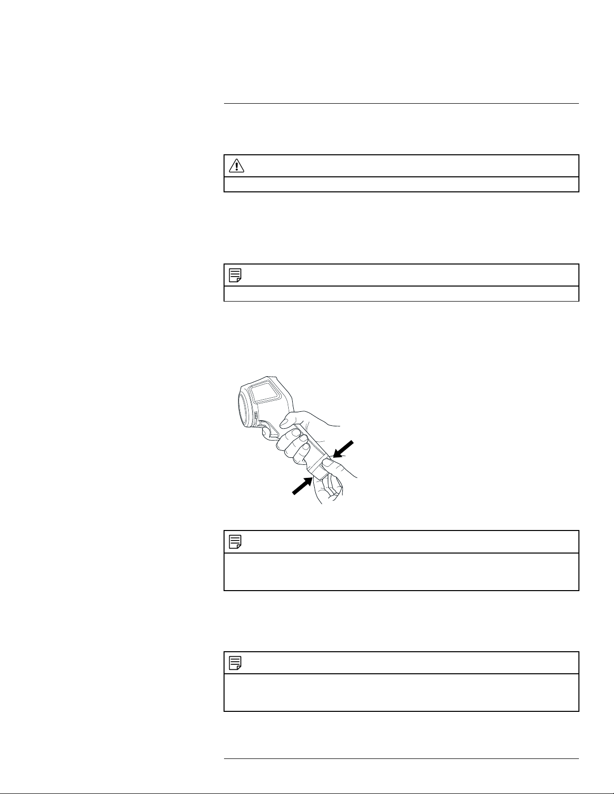
2. Push the On/off button
3. Open the lens cap by pushing the lens cap lever.
4. Aim the camera toward your target of interest.
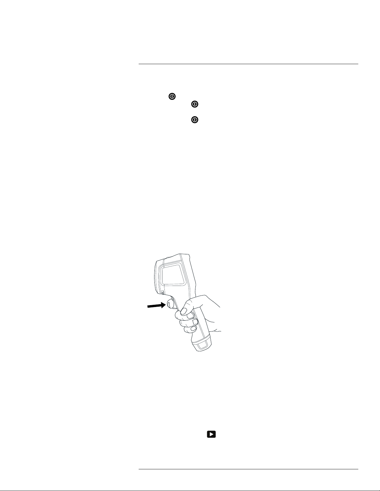
5. Pull the trigger to save an image.
(Optional steps)
6. Install FLIR Tools on your computer.
7. Start FLIR Tools.
8. Connect the camera to your computer, using the USB cable.
9. Import the images into FLIR Tools.
10. Create a PDF report in FLIR Tools.
to turn on the camera.
#T559828; r. AN/55574/55574; en-US
9
Page 18
6
Description
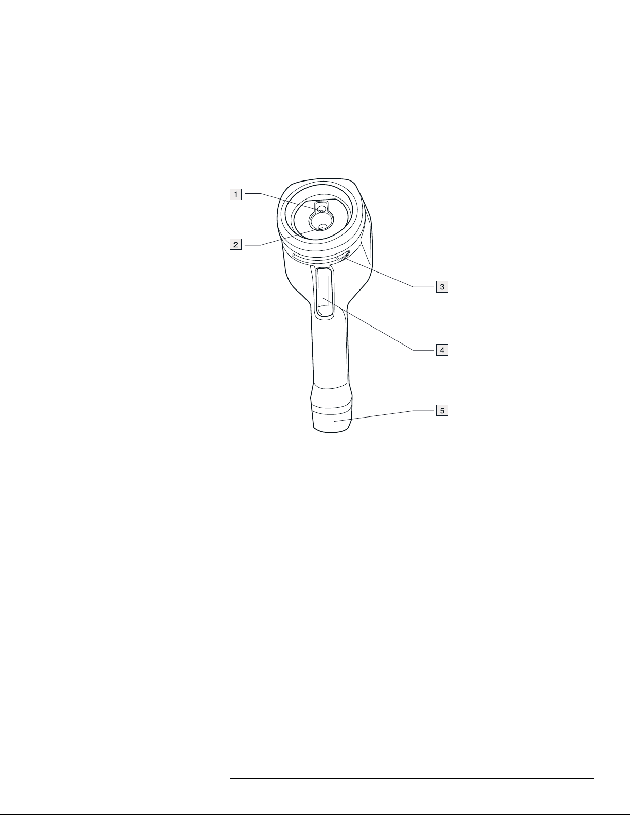
6.1 Camera parts
6.1.1 Figure
6.1.2 Explanation
1. Digital camera lens.
2. Infrared lens.
3. Lever to open and close the lens cap.
4. Trigger to save images.
5. Battery.
#T559828; r. AN/55574/55574; en-US
10
Page 19
Description6
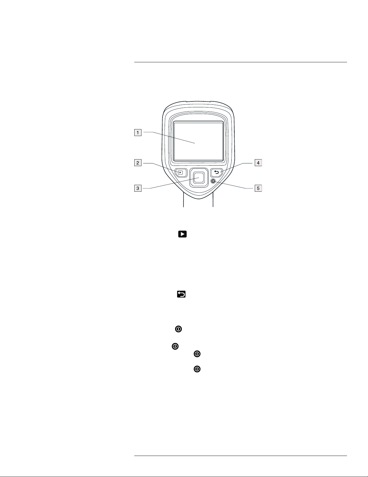
6.2 Keypad
6.2.1 Figure
6.2.2 Explanation
1. Camera screen.
2. Archive button
Function:
• Push to open the image archive.
3. Navigation pad.
Function:
• Push left/right or up/down to navigate in menus, submenus, and dialog boxes.
• Push the center to confirm.
4. Cancel button
Function:
• Push to cancel a choice.
• Push to go back into the menu system.
5. On/off button
Function:
• Push the
• Push and hold the
mode. The camera then automatically turns off after 48 hours.
• Push and hold the
.
.
button to turn on the camera.
button for less than 5 seconds to put the camera in standby
button for more than 10 seconds to turn off the camera.
#T559828; r. AN/55574/55574; en-US
11
Page 20
Description6
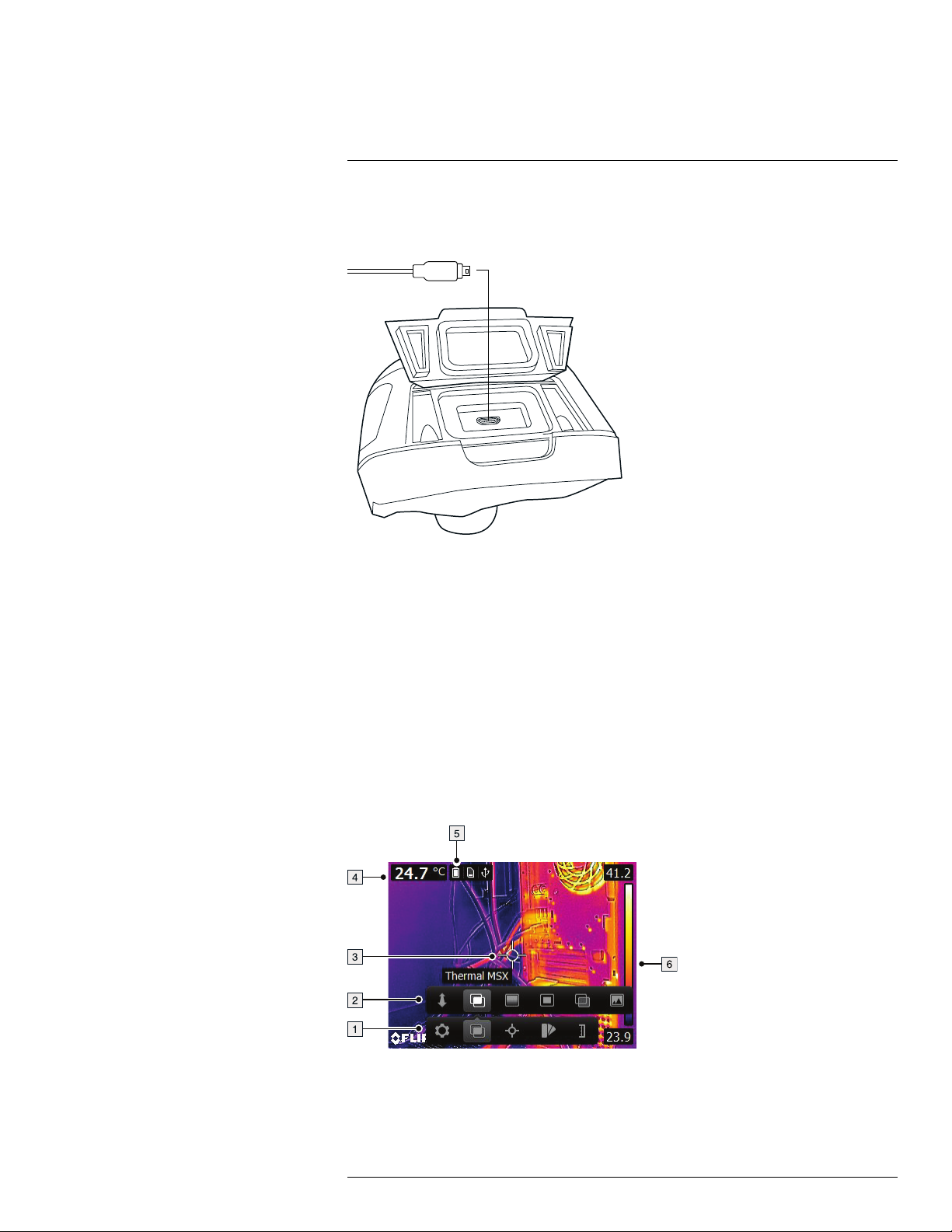
6.3 Connectors
6.3.1 Figure
6.3.2 Explanation
The purpose of this USB mini-B connector is the following:
• Charging the battery using the FLIR power supply.
• Charging the battery using a USB cable connected to a computer.
Note Charging the camera using a USB cable connected to a computer takes consid-
erably longer than using the FLIR power supply or the FLIR stand-alone battery charger.
• Moving images from the camera to a computer for further analysis in FLIR Tools.
Note Install FLIR Tools on your computer before you move the images.
6.4 Screen elements
6.4.1 Figure
6.4.2 Explanation
1. Main menu toolbar.
2. Submenu toolbar.
#T559828; r. AN/55574/55574; en-US
12
Page 21

Description6
3. Spotmeter.
4. Result table.
5. Status icons.
6. Temperature scale.
#T559828; r. AN/55574/55574; en-US
13
Page 22
7
Operation
7.1 Charging the battery
WARNING
Make sure that you install the socket-outlet near the equipment and that it is easy to get access to.
7.1.1 Charging the battery using the FLIR power supply
Follow this procedure:
1. Connect the power supply to a wall outlet.
2. Connect the power supply cable to the USB connector on the camera.
NOTE
The charging time for a fully depleted battery is 2 hours.
7.1.2 Charging the battery using the FLIR stand-alone battery charger.
Follow this procedure:
1. Connect the stand-alone battery charger to a wall outlet.
2. Remove the battery from the camera.
3. Put the battery into the stand-alone battery charger.
NOTE
• The charging time for a fully depleted battery is 2 hours.
• The battery is being charged when the blue LED is flashing.
• The battery is fully charged when the blue LED is continuous.
7.1.3 Charging the battery using a USB cable
Follow this procedure:
1. Connect the camera to a computer using a USB cable.
NOTE
• To charge the camera, the computer must be turned on.
• Charging the camera using a USB cable connected to a computer takes considerably longer than using the FLIR power supply or the FLIR stand-alone battery charger.
#T559828; r. AN/55574/55574; en-US
14
Page 23
7
Operation
7.2 Turning on and turning off the camera
• Push the button to turn on the camera.
• Push and hold the
mode. The camera then automatically turns off after 48 hours.
• Push and hold the
button for less than 5 seconds to put the camera in standby
button for more than 10 seconds to turn off the camera.
7.3 Saving an image
7.3.1 General
You can save multiple images to the internal camera memory.
7.3.2 Image capacity
Approximately 500 images can be saved to the internal camera memory.
7.3.3 Naming convention
The naming convention for images is FLIRxxxx.jpg, where xxxx is a unique counter.
7.3.4 Procedure
Follow this procedure:
1. To save an image, pull the trigger.
7.4 Recalling an image
7.4.1 General
When you save an image, it is stored in the internal camera memory. To display the image
again, you can recall it from the internal camera memory.
7.4.2 Procedure
Follow this procedure:
1. Push the Archive button
2. Push the navigation pad left/right or up/down to select the image you want to view.
3. Push the center of the navigation pad. This displays the selected image.
#T559828; r. AN/55574/55574; en-US
.
15
Page 24

7
Operation
4. To return to live mode, push the Cancel button
ton
.
repeatedly or push the Archive but-
7.5 Deleting an image
7.5.1 General
You can delete one or more images from the internal camera memory.
7.5.2 Procedure
Follow this procedure:
1. Push the Archive button
2. Push the navigation pad left/right or up/down to select the image you want to view.
3. Push the center of the navigation pad. This displays the selected image.
4. Push the center of the navigation pad. This displays a toolbar.
5. On the toolbar, select Delete
.
.
7.6 Deleting all images
7.6.1 General
You can delete all images from the internal camera memory.
7.6.2 Procedure
Follow this procedure:
1. Push the center of the navigation pad. This displays a toolbar.
2. On the toolbar, select Settings
3. In the dialog box, select Device settings. This displays a dialog box.
4. In the dialog box, select Reset options. This displays a dialog box.
5. In the dialog box, select Delete all saved images.
. This displays a dialog box.
7.7 Measuring a temperature using a spotmeter
7.7.1 General
You can measure a temperature using a spotmeter. This will display the temperature at the
position of the spotmeter on the screen.
7.7.2 Procedure
Follow this procedure:
1. Push the center of the navigation pad. This displays a toolbar.
2. On the toolbar, select Measurement
3. On the toolbar, select Center spot
The temperature at the position of the spotmeter will now be displayed in the top left
corner of the screen.
#T559828; r. AN/55574/55574; en-US
. This displays a toolbar.
.
16
Page 25
7
Operation
7.8 Measuring the hottest temperature within an
area
7.8.1 General
You can measure the hottest temperature within an area. This displays a moving spotmeter that indicates the hottest temperature.
7.8.2 Procedure
Follow this procedure:
1. Push the center of the navigation pad. This displays a toolbar.
2. On the toolbar, select Measurement
3. On the toolbar, select Hot spot
. This displays a toolbar.
.
7.9 Measuring the coldest temperature within
an area
7.9.1 General
You can measure the coldest temperature within an area. This displays a moving spotmeter that indicates the coldest temperature.
7.9.2 Procedure
Follow this procedure:
1. Push the center of the navigation pad. This displays a toolbar.
2. On the toolbar, select Measurement
3. On the toolbar, select Cold spot
. This displays a toolbar.
.
7.10 Hiding measurement tools
7.10.1 Procedure
Follow this procedure:
1. Push the center of the navigation pad. This displays a toolbar.
2. On the toolbar, select Measurement
3. On the toolbar, select No measurements
. This displays a toolbar.
.
7.11 Changing the color palette
7.11.1 General
You can change the color palette that the camera uses to display different temperatures. A
different palette can make it easier to analyze an image.
7.11.2 Procedure
Follow this procedure:
1. Push the center of the navigation pad. This displays a toolbar.
2. On the toolbar, select Color
#T559828; r. AN/55574/55574; en-US
. This displays a toolbar.
17
Page 26
7
Operation
3. On the toolbar, select a new color palette.
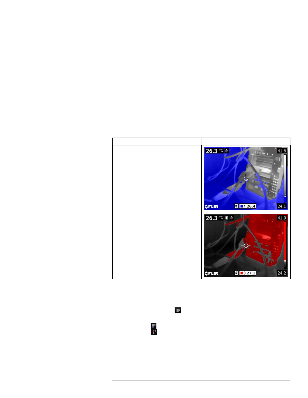
7.12 Working with color alarms
7.12.1 General
By using color alarms (isotherms), anomalies can easily be discovered in an infrared image. The isotherm command applies a contrasting color to all pixels with a temperature
above or below the specified temperature level.
7.12.2 Image examples
This table explains the different color alarms (isotherms).
Color alarm
Below alarm
Image
Above alarm
7.12.3 Procedure
Follow this procedure:
1. Push the center of the navigation pad. This displays a toolbar.
2. On the toolbar, select Color
. This displays a toolbar.
3. On the toolbar, select the type of alarm:
• Below alarm
• Above alarm
.
.
4. Push the center of the navigation pad. The threshold temperature is displayed at the
bottom of the screen.
5. To change the threshold temperature, push the navigation pad up/down.
#T559828; r. AN/55574/55574; en-US
18
Page 27
7
Operation
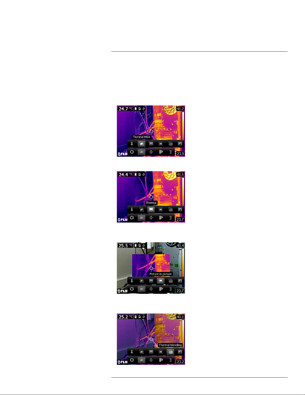
7.13 Changing image mode
7.13.1 General
The camera can operate in five different image modes:
• Thermal MSX (Multi Spectral Dynamic Imaging): The camera displays an infrared image where the edges of the objects are enhanced.
• Thermal: The camera displays a fully thermal image.
• Picture-in-picture: The camera displays a digital camera image with a superimposed infrared image frame.
• Thermal blending: The camera displays a blended image that uses a mix of infrared pixels and digital photo pixels. The mixing level can be adjusted.
#T559828; r. AN/55574/55574; en-US
19
Page 28
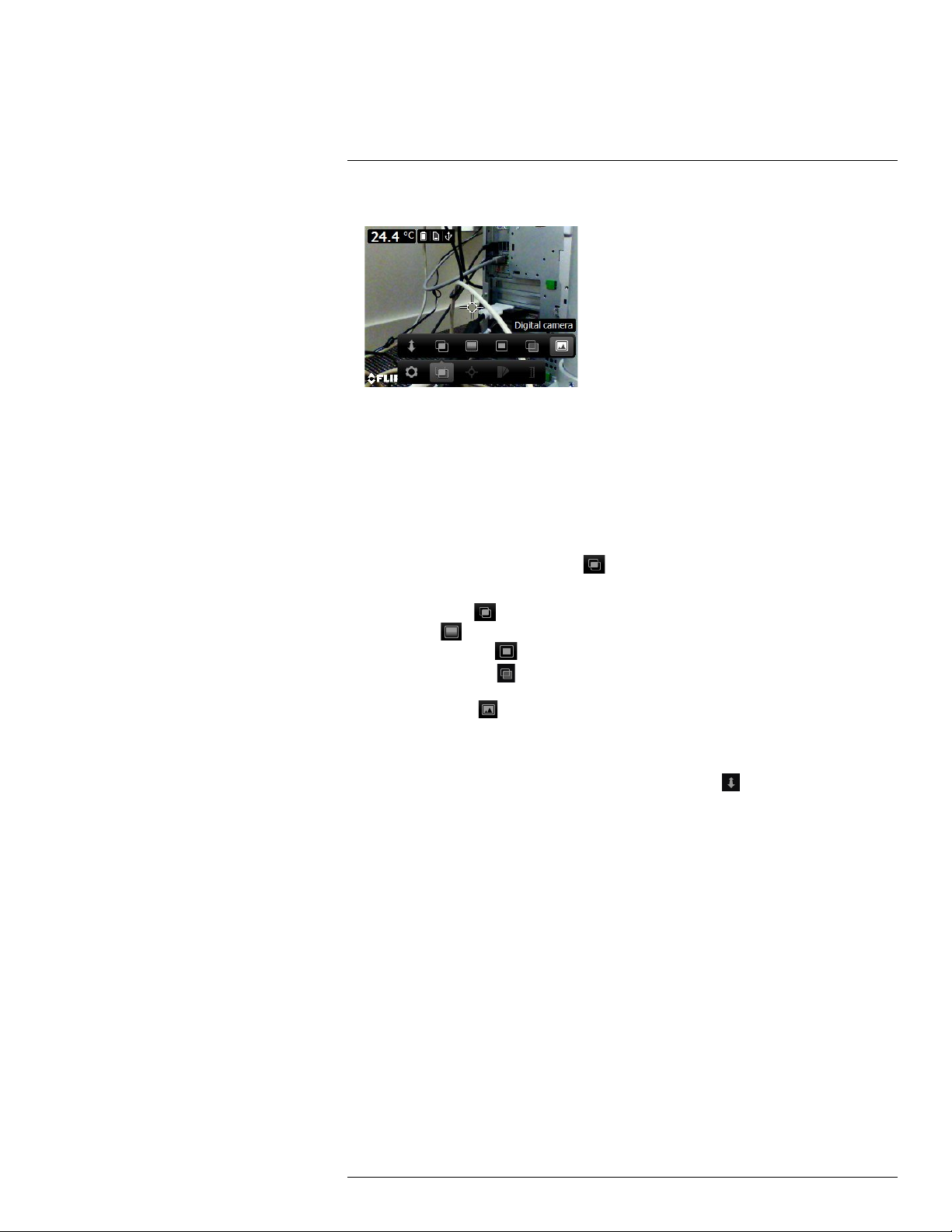
7
Operation
• Digital camera: The camera displays a digital camera image.
To display a good fusion image (Thermal MSX, Picture-in-picture, and Thermal blending
modes), the camera must make adjustments to compensate for the small difference in position between the digital camera lens and the infrared lens. To adjust the image accurately, the camera requires the alignment distance (i.e., the distance to the object).
7.13.2 Procedure
Follow this procedure:
1. Push the center of the navigation pad. This displays a toolbar.
2. On the toolbar, select Image mode
3. On the toolbar, select one of the following:
. This displays a toolbar.
• Thermal MSX
• Thermal
• Picture-in-picture
• Thermal blending
level.
• Digital camera
4. If you have selected the Thermal MSX, Picture-in-picture, or Thermal blending mode,
also set the distance to the object by doing the following:
• On the Image mode toolbar, select Alignment distance
box.
• In the dialog box, select the distance to the object.
.
.
.
. This displays a dialog box where you can select the mixing
.
. This displays a dialog
7.14 Changing the temperature scale mode
7.14.1 General
The camera can, depending on the camera model, operate in different temperature scale
modes:
• Auto mode: In this mode, the camera is continuously auto-adjusted for the best image
brightness and contrast.
• Manual mode: This mode allows manual adjustments of the temperature span and the
temperature level.
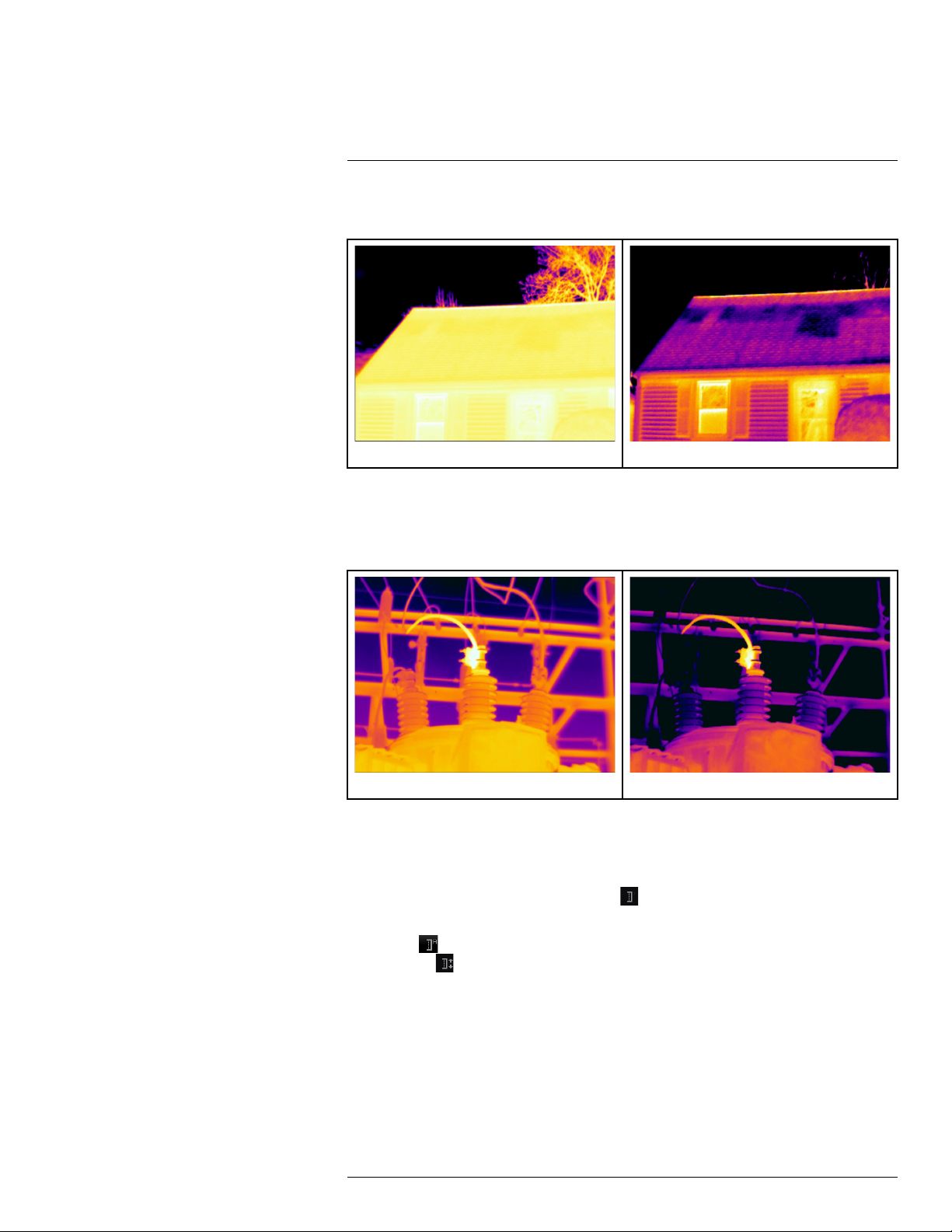
7.14.2 When to use Manual mode
7.14.2.1 Example 1
Here are two infrared images of a building. In the left image, which is auto-adjusted, the
large temperature span between the clear sky and the heated building makes a correct
#T559828; r. AN/55574/55574; en-US
20
Page 29
7
Operation
analysis difficult. You can analyze the building in more detail if you change the temperature
scale to values close to the temperature of the building.
Automatic Manual
7.14.2.2 Example 2
Here are two infrared images of an isolator in a power line. To make it easier to analyze
the temperature variations in the isolator, the temperature scale in the right image has
been changed to values close to the temperature of the isolator.
Automatic Manual
7.14.3 Procedure
Follow this procedure:
1. Push the center of the navigation pad. This displays a toolbar.
2. On the toolbar, select Temperature scale
. This displays a toolbar.
3. On the toolbar, select one of the following:
• Auto
• Manual
.
.
4. To change the temperature span and the temperature level in Manual mode, do the
following:
• Push the navigation pad left/right to select (highlight) the maximum and/or minimum
temperature.
• Push the navigation pad up/down to change the value of the highlighted
temperature.
#T559828; r. AN/55574/55574; en-US
21
Page 30

7
Operation
7.15 Changing the camera temperature range
7.15.1 General
The camera is calibrated for different temperature ranges. Available temperature range
options are dependent on the camera model.
For accurate temperature measurements, you must change the Camera temperature
range setting to suit the expected temperature of the object you are inspecting.
Note For more information, see section 16 About calibration, page 101.
7.15.2 Procedure
Follow this procedure:
1. Push the navigation pad to display the menu system.
2. Select
3. Select Camera temperature range and push the navigation pad. This displays a dialog
box.
4. Select the appropriate temperature range and push the navigation pad.
(Settings) and push the navigation pad. This displays the Settings menu.
7.16 Setting the emissivity as a surface
property
7.16.1 General
To measure temperatures accurately, the camera must know what kind of surface you are
measuring. You can choose between the following surface properties:
• Matt.
• Semi-matt.
• Semi-glossy.
For more information about emissivity, see section 15 Thermographic measurement tech-
niques, page 96.
7.16.2 Procedure
Follow this procedure:
1. Push the center of the navigation pad. This displays a toolbar.
2. On the toolbar, select Settings
3. In the dialog box, select Measurement parameters. This displays a dialog box.
4. In the dialog box, select Emissivity. This displays a dialog box.
5. In the dialog box, select one of the following:
• Matt.
• Semi-matt.
• Semi-glossy.
. This displays a dialog box.
7.17 Setting the emissivity as a custom material
7.17.1 General
Instead of specifying a surface property as matt, semi-matt or semi-glossy, you can specify
a custom material from a list of materials.
#T559828; r. AN/55574/55574; en-US
22
Page 31

7
Operation
For more information about emissivity, see section 15 Thermographic measurement techniques, page 96.
7.17.2 Procedure
Follow this procedure:
1. Push the center of the navigation pad. This displays a toolbar.
2. On the toolbar, select Settings
3. In the dialog box, select Measurement parameters. This displays a dialog box.
4. In the dialog box, select Emissivity. This displays a dialog box.
5. In the dialog box, select Custom material. This displays a list of materials with known
emissivities.
6. In the list, select the material.
. This displays a dialog box.
7.18 Changing the emissivity as a custom value
7.18.1 General
For very precise measurements, you may need to set the emissivity, instead of selecting a
surface property or a custom material. You also need to understand how emissivity and reflectivity affect measurements, rather than just simply selecting a surface property.
Emissivity is a property that indicates how much radiation originates from an object as opposed to being reflected by it. A lower value indicates that a larger proportion is being reflected, while a high value indicates that a lower proportion is being reflected.
Polished stainless steel, for example, has an emissivity of 0.14, while a structured PVC
floor typically has an emissivity of 0.93.
For more information about emissivity, see section 15 Thermographic measurement tech-
niques, page 96.
7.18.2 Procedure
Follow this procedure:
1. Push the center of the navigation pad. This displays a toolbar.
2. On the toolbar, select Settings
3. In the dialog box, select Measurement parameters. This displays a dialog box.
4. In the dialog box, select Emissivity. This displays a dialog box.
5. In the dialog box, select Custom value. This displays a dialog box where you can set a
custom value.
. This displays a dialog box.
7.19 Changing the reflected apparent
temperature
7.19.1 General
This parameter is used to compensate for the radiation reflected by the object. If the emissivity is low and the object temperature significantly different from that of the reflected temperature, it will be important to set and compensate for the reflected apparent temperature
correctly.
For more information about reflected apparent temperature, see section 15 Thermo-
graphic measurement techniques, page 96.
#T559828; r. AN/55574/55574; en-US
23
Page 32

7
Operation
7.19.2 Procedure
Follow this procedure:
1. Push the center of the navigation pad. This displays a toolbar.
2. On the toolbar, select Settings
3. In the dialog box, select Measurement parameters. This displays a dialog box.
4. In the dialog box, select Reflected apparent temperature. This displays a dialog box
where you can set a value.
. This displays a dialog box.
7.20 Changing the distance between the object
and the camera
7.20.1 General
To measure temperatures accurately, the camera requires the distance between the camera and the object.
7.20.2 Procedure
Follow this procedure:
1. Push the center of the navigation pad. This displays a toolbar.
2. On the toolbar, select Settings
3. In the dialog box, select Measurement parameters. This displays a dialog box.
4. In the dialog box, select Distance. This displays a dialog box where you can select a
distance.
. This displays a dialog box.
7.21 Performing a non-uniformity correction
(NUC)
7.21.1 What is a non-uniformity correction?
A non-uniformity correction is an image correction carried out by the camera software to
compensate for different sensitivities of detector elements and other optical and geometrical disturbances
7.21.2 When to perform a non-uniformity correction?
The non-uniformity correction process should be carried out whenever the output image
becomes spatially noisy. The output can become spatially noisy when the ambient temperature changes (such as from day to night operation, and vice versa).
7.21.3 Procedure
1
.
To perform a non-uniformity correction, push and hold the Image archive button
more than 2 seconds.
1. Definition from the impending international adoption of DIN 54190-3 (Non-destructive testing – Thermographic
testing – Part 3: Terms and definitions).
#T559828; r. AN/55574/55574; en-US
for
24
Page 33

7
Operation
7.22 Configuring Wi-Fi
Depending on your camera configuration, you can connect the camera to a wireless local
area network (WLAN) using Wi-Fi, or let the camera provide Wi-Fi access to another
device.
You can connect the camera in two different ways:
• Most common use: Setting up a peer-to-peer connection (also called an ad hoc or P2P
connection). This method is primarily used with other devices, e.g., an iPhone or iPad.
• Less common use: Connecting the camera to a WLAN.
7.22.1 Setting up a peer-to-peer connection (most common use)
Follow this procedure:
1. Push the center of the navigation pad. This displays a toolbar.
2. On the toolbar, select Settings
3. Select Device settings and push the center of the navigation pad.
4. Select Wi-Fi and push the center of the navigation pad.
5. Select Share and push the center of the navigation pad.
6. (Optional step.) To display and change the parameters, select Settings and push the
center of the navigation pad.
• To change the channel (the channel that the camera is broadcasting on), select
Channel and push the center of the navigation pad.
• To activate WEP (encryption algorithm), select WEP and push the center of the nav-
igation pad. This will check the WEP check box.
• To change the WEP password, select Password and push the center of the naviga-
tion pad.
Note These parameters are set for your camera’s network. They will be used by the
external device to connect that device to the network.
. This displays a dialog box.
7.22.2 Connecting the camera to a wireless local area network (less common
use)
Follow this procedure:
1. Push the center of the navigation pad. This displays a toolbar.
2. On the toolbar, select Settings
3. Select Device settings and push the center of the navigation pad.
4. Select Wi-Fi and push the center of the navigation pad.
5. Select Connect to network and push the center of the navigation pad.
6. To display a list of the available networks, select Networks and push the center of the
navigation pad.
7. Select one of the available networks.
Password-protected networks are indicated with a padlock icon, and for these you will
need to enter a password.
Note Some networks do not broadcast their existence. To connect to such a network,
select Add network... and set all parameters manually according to that network.
. This displays a dialog box.
7.23 Changing the settings
7.23.1 General
You can change a variety of settings for the camera.
#T559828; r. AN/55574/55574; en-US
25
Page 34

7
Operation
The Settings menu includes the following:
• Measurement parameters.
• Camera temperature range.
• Save options.
• Device settings.
7.23.1.1 Measurement parameters
• Emissivity.
• Reflected temperature.
• Distance.
7.23.1.2 Camera temperature range
For accurate temperature measurements, you must change the Camera temperature
range setting to suit the expected temperature of the object you are inspecting.
Available temperature range options are dependent on the camera model. The unit (℃ or
℉) depends on the temperature unit setting, see section 7.23.1.4 Device settings, page
26.
7.23.1.3 Save options
• Photo as separate JPEG: When this menu command is selected, the digital photo from
the visual camera is saved at its full field of view as a separate JPEG image.
7.23.1.4 Device settings
• Language, time & units:
◦ Language.
◦ Temperature unit.
◦ Distance unit.
◦ Date & time.
◦ Date & time format.
• Wi-Fi
◦ Off
◦ Share
◦ Connect to network
– Networks
• Reset options:
◦ Reset default camera mode.
◦ Reset device settings to factory default.
◦ Delete all saved images.
• Auto power off.
• Display intensity.
• Demonstration mode: This menu command provides a camera mode that displays vari-
ous images without any user interventions. The camera mode is intended for demonstration purposes or when displaying the camera in a store.
◦ Off.
◦ Electrical applications.
◦ Building applications.
• Camera information: This menu command displays various items of information about
the camera, such as the model, serial number, and software version.
#T559828; r. AN/55574/55574; en-US
26
Page 35

7
Operation
7.23.2 Procedure
Follow this procedure:
1. Push the center of the navigation pad. This displays a toolbar.
2. On the toolbar, select Settings
3. In the dialog box, select the setting that you want to change and use the navigation
pad to display additional dialog boxes.
. This displays a dialog box.
7.24 Updating the camera
7.24.1 General
To take advantage of our latest camera firmware, it is important that you keep your camera
updated. You update your camera using FLIR Tools.
7.24.2 Procedure
Follow this procedure:
1. Start FLIR Tools.
2. Start the camera.
3. Connect the camera to the computer using the USB cable.
4. On the Help menu in FLIR Tools, click Check for updates.
5. Follow the on-screen instructions.
#T559828; r. AN/55574/55574; en-US
27
Page 36

8
Technical data
Table of contents
8.1 Online field-of-view calculator......... ................................. ................... 28
8.2 Note about technical data...................... ................................. ............ 28
8.3 Note about authoritative versions................... .. .. ........................... .. .. .. 28
8.4 FLIR E5xt............................ ............................... .. ............................. 29
8.5 FLIR E5xt (incl. Wi-Fi)............................. ............................... ............. 32
8.6 FLIR E6xt............................ ............................... .. ............................. 36
8.7 FLIR E6xt (incl. Wi-Fi)............................. ............................... ............. 39
8.8 FLIR E8xt............................ ............................... .. ............................. 43
8.9 FLIR E8xt (incl. Wi-Fi)............................. ............................... ............. 47
8.10 FLIR E4 ...................... .. .. ............................. .. .. ............................... .. 51
8.11 FLIR E4 (incl. Wi-Fi) ....................... ................................. ................... 54
8.12 FLIR E5 ...................... .. .. ............................. .. .. ............................... .. 58
8.13 FLIR E5 (incl. Wi-Fi) ....................... ................................. ................... 61
8.14 FLIR E6 ...................... .. .. ............................. .. .. ............................... .. 65
8.15 FLIR E6 (incl. Wi-Fi) ....................... ................................. ................... 68
8.16 FLIR E8 ...................... .. .. ............................. .. .. ............................... .. 72
8.17 FLIR E8 (incl. Wi-Fi) ....................... ................................. ................... 75
8.1 Online field-of-view calculator
Please visit http://support.flir.com and click the photo of the camera series for field-of-view
tables for all lens–camera combinations.
8.2 Note about technical data
FLIR Systems reserves the right to change specifications at any time without prior notice.
Please check http://support.flir.com for latest changes.
8.3 Note about authoritative versions
The authoritative version of this publication is English. In the event of divergences due to
translation errors, the English text has precedence.
Any late changes are first implemented in English.
#T559828; r. AN/55574/55574; en-US
28
Page 37

Technical data8
8.4 FLIR E5xt
P/N: 63905-0601
Rev.: 55567
General description
The FLIR Ex series cameras are point-and-shoot infrared cameras that give you access to the infrared
world. A FLIR Ex series camera is an affordable replacement for an infrared thermometer, providing a
thermal image with temperature information in every pixel. The new MSX and visual formats make the
cameras incomparably easy to use.
The FLIR Ex series cameras are user-friendly, compact, and rugged, for use in harsh environments. The
wide field of view makes them the perfect choice for building applications.
Benefits:
• Easy to use: The FLIR Ex series cameras are fully automatic and focus-free with an intuitive interface
for simple measurements in thermal, visual, or MSX mode.
• Compact and rugged: The FLIR Ex series cameras’ low weight of 0.575 kg and the accessory belt
pouch make them easy to bring along at all times. Their rugged design can withstand a 2 m drop test,
and ensures reliability, even in harsh environments.
• Ground breaking affordability: The FLIR Ex series cameras are the most affordable infrared cameras
on the market.
Imaging and optical data
IR resolution 160 × 120 pixels
Thermal sensitivity/NETD < 0.10°C (0.27°F) / < 100 mK
Field of view (FOV)
Minimum focus distance 0.5 m (1.6 ft.)
Spatial resolution (IFOV) 5.2 mrad
F-number 1.5
Image frequency 9 Hz
Focus Focus free
Detector data
Detector type Focal plane array (FPA), uncooled microbolometer
Spectral range
Image presentation
Display
Image adjustment Automatic adjust/lock image
Image presentation modes
Image modes
Multi Spectral Dynamic Imaging (MSX) IR image with enhanced detail presentation
Picture in Picture IR area on visual image
45° × 34°
7.5–13 µm
3.0 in. 320 × 240 color LCD
Thermal MSX, Thermal, Picture-in-Picture, Thermal blending, Digital camera.
#T559828; r. AN/55574/55574; en-US
29
Page 38

Technical data8
Measurement
Object temperature range –20°C to +250°C (–4°F to +482°F)
10°C to 400°C (50°F to +752°F)
Accuracy ±2°C (±3.6°F) or ±2% of reading, for ambient tem-
Measurement analysis
Spotmeter Center spot
Area
Isotherm Above alarm, Below alarm
Emissivity correction Variable from 0.1 to 1.0
Emissivity table Emissivity table of predefined materials
Reflected apparent temperature correction Automatic, based on input of reflected temperature
Set-up
Color palettes
Set-up commands Local adaptation of units, language, date and time
perature 10°C to 35°C (+50°F to 95°F) and object
temperature above +0°C (+32°F)
Box with max./min.
Black and white, iron and rainbow
formats
Storage of images
File formats Standard JPEG, 14-bit measurement data
Digital camera
Digital camera, resolution 640 × 480
Digital camera, FOV
Data communication interfaces
Interfaces USB Micro: Data transfer to and from PC and Mac
Power system
Battery type Rechargeable Li ion battery
Battery voltage 3.6 V
Battery operating time
Charging system Battery is charged inside the camera or in specific
Charging time
Power management Automatic shut-down
AC operation AC adapter, 90–260 VAC input, 5 VDC output to
included
55° × 43°
device
Approx. 4 hours at +25°C (+77°F) ambient temperature and typical use
charger.
2.5 hours to 90% capacity in camera. 2 hours in
charger.
camera
Environmental data
Operating temperature range –15°C to +50°C (+5°F to +122°F)
Storage temperature range –40°C to +70°C (–40°F to +158°F)
Humidity (operating and storage) IEC 60068-2-30/24 h 95% relative humidity
#T559828; r. AN/55574/55574; en-US
30
Page 39

Technical data8
Environmental data
EMC
Encapsulation
Shock 25 g (IEC 60068-2-27)
Vibration 2 g (IEC 60068-2-6)
Drop 2 m (6.6 ft.)
Physical data
Camera weight, incl. battery 0.575 kg (1.27 lb.)
Camera size (L × W × H) 244 × 95 × 140 mm (9.6 × 3.7 × 5.5 in.)
Color
• WEEE 2012/19/EC
• RoHs 2011/65/EC
• C-Tick
• EN 61000-6-3
• EN 61000-6-2
• FCC 47 CFR Part 15 Class B
IP 54 (IEC 60529)
Black and gray
Certifications
Certification UL, CSA, CE, PSE and CCC
Shipping information
Packaging, type Cardboard box
List of contents
Packaging, weight 2.9 kg (6.4 lb.)
Packaging, size 385 × 165 × 315 mm (15.2 × 6.5 × 12.4 in.)
EAN-13 4743254003972
UPC-12
Country of origin
• Infrared camera
• Hard transport case
• Battery (inside camera)
• USB cable
• Power supply/charger with EU, UK, US and
Australian plugs
• Printed documentation
845188018757
Estonia
Supplies & accessories:
• T911093; Tool belt
• T911689ACC; Pouch for FLIR E-series
• T198528; Hard transport case FLIR Ex-series
• T198531; Battery charger incl power supply
• T198532; Car charger
• T198534; Power supply USB-micro
• T198529; Pouch FLIR Ex and ix series
• T198533; USB cable Std A <-> Micro B
• T199362ACC; Battery Li-ion 3.6 V, 2.6 Ah, 9.4 Wh
• T198583; FLIR Tools+ (download card incl. license key)
• T199233; FLIR Atlas SDK for .NET
• T199234; FLIR Atlas SDK for MATLAB
• INST-EW-0110; Extended Warranty 1 Year for AX8, E4, E5
• INST-EWGM-0110; Premium Service Package for E4, E5
• INST-GM-0115; General Maintenance Package for E4, E5, ix, Kx
#T559828; r. AN/55574/55574; en-US
31
Page 40

Technical data8
8.5 FLIR E5xt (incl. Wi-Fi)
P/N: 63909-1004
Rev.: 55567
General description
The FLIR Ex series cameras are point-and-shoot infrared cameras that give you access to the infrared
world. A FLIR Ex series camera is an affordable replacement for an infrared thermometer, providing a
thermal image with temperature information in every pixel. The new MSX and visual formats make the
cameras incomparably easy to use.
The FLIR Ex series cameras are user-friendly, compact, and rugged, for use in harsh environments. The
wide field of view makes them the perfect choice for building applications.
Benefits:
• Easy to use: The FLIR Ex series cameras are fully automatic and focus-free with an intuitive interface
for simple measurements in thermal, visual, or MSX mode.
• Compact and rugged: The FLIR Ex series cameras’ low weight of 0.575 kg and the accessory belt
pouch make them easy to bring along at all times. Their rugged design can withstand a 2 m drop test,
and ensures reliability, even in harsh environments.
• Ground breaking affordability: The FLIR Ex series cameras are the most affordable infrared cameras
on the market.
Imaging and optical data
IR resolution 160 × 120 pixels
Thermal sensitivity/NETD < 0.10°C (0.27°F) / < 100 mK
Field of view (FOV)
Minimum focus distance 0.5 m (1.6 ft.)
Spatial resolution (IFOV)
F-number 1.5
Image frequency 9 Hz
Focus Focus free
Detector data
Detector type Focal plane array (FPA), uncooled microbolometer
Spectral range
Image presentation
Display
Image adjustment Automatic adjust/lock image
Image presentation modes
Image modes
Multi Spectral Dynamic Imaging (MSX)
Picture-in-Picture IR area on visual image
45° × 34°
5.2 mrad
7.5–13 µm
3.0 in. 320 × 240 color LCD
Thermal MSX, Thermal, Picture-in-Picture, Thermal blending, Digital camera.
IR image with enhanced detail presentation
#T559828; r. AN/55574/55574; en-US
32
Page 41

Technical data8
Measurement
Object temperature range –20°C to +250°C (–4°F to +482°F)
10°C to 400°C (50°F to +752°F)
Accuracy ±2°C (±3.6°F) or ±2% of reading, for ambient tem-
Measurement analysis
Spotmeter Center spot
Area
Isotherm Above alarm, Below alarm
Emissivity correction Variable from 0.1 to 1.0
Emissivity table Emissivity table of predefined materials
Reflected apparent temperature correction Automatic, based on input of reflected temperature
Set-up
Color palettes
Set-up commands Local adaptation of units, language, date and time
perature 10°C to 35°C (+50°F to 95°F) and object
temperature above +0°C (+32°F)
Box with max./min.
Black and white, iron and rainbow
formats
Storage of images
File formats Standard JPEG, 14-bit measurement data
Digital camera
Digital camera, resolution 640 × 480
Digital camera, FOV
Data communication interfaces
Interfaces USB Micro: Data transfer to and from PC and Mac
Wi-Fi Peer-to-peer (ad hoc) or infrastructure (network)
Radio
Wi-Fi
Power system
Battery type Rechargeable Li ion battery
Battery voltage 3.6 V
Battery operating time Approx. 4 hours at +25°C (+77°F) ambient temper-
Charging system Battery is charged inside the camera or in specific
Charging time 2.5 hours to 90% capacity in camera. 2 hours in
included
55° × 43°
device
• Standard: 802.11 b/g/n
• Frequency range:
◦ 2400–2480 MHz
◦ 5150–5260 MHz
• Max. output power: 15 dBm
ature and typical use
charger.
charger.
#T559828; r. AN/55574/55574; en-US
33
Page 42

Technical data8
Power system
Power management Automatic shut-down
AC operation AC adapter, 90–260 VAC input, 5 VDC output to
Environmental data
Operating temperature range –15°C to +50°C (+5°F to +122°F)
Storage temperature range –40°C to +70°C (–40°F to +158°F)
Humidity (operating and storage) IEC 60068-2-30/24 h 95% relative humidity
EMC
Radio spectrum
Encapsulation
Shock 25 g (IEC 60068-2-27)
Vibration 2 g (IEC 60068-2-6)
Drop 2 m (6.6 ft.)
camera
• WEEE 2012/19/EC
• RoHs 2011/65/EC
• C-Tick
• EN 61000-6-3
• EN 61000-6-2
• FCC 47 CFR Part 15 Class B
• Standard: 802.11 b/g/n
• Frequency range:
◦ 2400–2480 MHz
◦ 5150–5260 MHz
• Max. output power: 15 dBm
IP 54 (IEC 60529)
Physical data
Camera weight, incl. battery 0.575 kg (1.27 lb.)
Camera size (L × W × H) 244 × 95 × 140 mm (9.6 × 3.7 × 5.5 in.)
Color
Certifications
Certification UL, CSA, CE, PSE and CCC
Shipping information
Packaging, type
List of contents
Packaging, weight 2.9 kg (6.4 lb.)
Packaging, size 385 × 165 × 315 mm (15.2 × 6.5 × 12.4 in.)
EAN-13 4743254004009
UPC-12
Country of origin
Black and gray
Cardboard box
• Infrared camera
• Hard transport case
• Battery (inside camera)
• USB cable
• Power supply/charger with EU, UK, US and
Australian plugs
• Printed documentation
845188018788
Estonia
#T559828; r. AN/55574/55574; en-US
34
Page 43

Technical data8
Supplies & accessories:
• T911093; Tool belt
• T911689ACC; Pouch for FLIR E-series
• T198528; Hard transport case FLIR Ex-series
• T198531; Battery charger incl power supply
• T198532; Car charger
• T198534; Power supply USB-micro
• T198529; Pouch FLIR Ex and ix series
• T198533; USB cable Std A <-> Micro B
• T199362ACC; Battery Li-ion 3.6 V, 2.6 Ah, 9.4 Wh
• T198583; FLIR Tools+ (download card incl. license key)
• T199233; FLIR Atlas SDK for .NET
• T199234; FLIR Atlas SDK for MATLAB
• INST-EW-0110; Extended Warranty 1 Year for AX8, E4, E5
• INST-EWGM-0110; Premium Service Package for E4, E5
• INST-GM-0115; General Maintenance Package for E4, E5, ix, Kx
#T559828; r. AN/55574/55574; en-US
35
Page 44

Technical data8
8.6 FLIR E6xt
P/N: 63902-0302
Rev.: 55567
General description
The FLIR Ex series cameras are point-and-shoot infrared cameras that give you access to the infrared
world. A FLIR Ex series camera is an affordable replacement for an infrared thermometer, providing a
thermal image with temperature information in every pixel. The new MSX and visual formats make the
cameras incomparably easy to use.
The FLIR Ex series cameras are user-friendly, compact, and rugged, for use in harsh environments. The
wide field of view makes them the perfect choice for building applications.
Benefits:
• Easy to use: The FLIR Ex series cameras are fully automatic and focus-free with an intuitive interface
for simple measurements in thermal, visual, or MSX mode.
• Compact and rugged: The FLIR Ex series cameras’ low weight of 0.575 kg and the accessory belt
pouch make them easy to bring along at all times. Their rugged design can withstand a 2 m drop test,
and ensures reliability, even in harsh environments.
• Ground breaking affordability: The FLIR Ex series cameras are the most affordable infrared cameras
on the market.
Imaging and optical data
IR resolution 240 × 180 pixels
Thermal sensitivity/NETD < 0.06°C (0.11°F) / < 60 mK
Field of view (FOV)
Minimum focus distance 0.5 m (1.6 ft.)
Spatial resolution (IFOV) 3.4 mrad
F-number 1.5
Image frequency 9 Hz
Focus Focus free
Detector data
Detector type Focal plane array (FPA), uncooled microbolometer
Spectral range
Image presentation
Display
Image adjustment Automatic/Manual
Image presentation modes
Image modes Thermal MSX, Thermal, Picture-in-Picture, Ther-
Multi Spectral Dynamic Imaging (MSX)
Picture in Picture IR area on visual image
45° × 34°
7.5–13 µm
3.0 in. 320 × 240 color LCD
mal blending, Digital camera.
IR image with enhanced detail presentation
#T559828; r. AN/55574/55574; en-US
36
Page 45

Technical data8
Measurement
Object temperature range –20°C to +250°C (–4°F to +482°F)
10°C to 550°C (50°F to +1022°F)
Accuracy ±2°C (±3.6°F) or ±2% of reading, for ambient tem-
Measurement analysis
Spotmeter Center spot
Area
Isotherm Above alarm, Below alarm
Emissivity correction Variable from 0.1 to 1.0
Emissivity table Emissivity table of predefined materials
Reflected apparent temperature correction Automatic, based on input of reflected temperature
Set-up
Color palettes
Set-up commands Local adaptation of units, language, date and time
perature 10°C to 35°C (+50°F to 95°F) and object
temperature above +0°C (+32°F)
Box with max./min.
Black and white, iron and rainbow
formats
Storage of images
File formats Standard JPEG, 14-bit measurement data
Digital camera
Digital camera, resolution 640 × 480
Digital camera, FOV
Data communication interfaces
Interfaces USB Micro: Data transfer to and from PC and Mac
Power system
Battery type Rechargeable Li ion battery
Battery voltage 3.6 V
Battery operating time
Charging system Battery is charged inside the camera or in specific
Charging time
Power management Automatic shut-down
AC operation AC adapter, 90–260 VAC input, 5 VDC output to
included
55° × 43°
device
Approx. 4 hours at +25°C (+77°F) ambient temperature and typical use
charger.
2.5 hours to 90% capacity in camera. 2 hours in
charger.
camera
Environmental data
Operating temperature range –15°C to +50°C (+5°F to +122°F)
Storage temperature range –40°C to +70°C (–40°F to +158°F)
Humidity (operating and storage) IEC 60068-2-30/24 h 95% relative humidity
#T559828; r. AN/55574/55574; en-US
37
Page 46

Technical data8
Environmental data
EMC
Encapsulation
Shock 25 g (IEC 60068-2-27)
Vibration 2 g (IEC 60068-2-6)
Drop 2 m (6.6 ft.)
Physical data
Camera weight, incl. battery 0.575 kg (1.27 lb.)
Camera size (L × W × H) 244 × 95 × 140 mm (9.6 × 3.7 × 5.5 in.)
Color
• WEEE 2012/19/EC
• RoHs 2011/65/EC
• C-Tick
• EN 61000-6-3
• EN 61000-6-2
• FCC 47 CFR Part 15 Class B
IP 54 (IEC 60529)
Black and gray
Certifications
Certification UL, CSA, CE, PSE and CCC
Shipping information
Packaging, type Cardboard box
List of contents
Packaging, weight 2.9 kg (6.4 lb.)
Packaging, size 385 × 165 × 315 mm (15.2 × 6.5 × 12.4 in.)
EAN-13 4743254003989
UPC-12
Country of origin
• Infrared camera
• Hard transport case
• Battery (inside camera)
• USB cable
• Power supply/charger with EU, UK, US and
Australian plugs
• Printed documentation
845188018764
Estonia
Supplies & accessories:
• T911093; Tool belt
• T911689ACC; Pouch for FLIR E-series
• T198528; Hard transport case FLIR Ex-series
• T198531; Battery charger incl power supply
• T198532; Car charger
• T198534; Power supply USB-micro
• T198529; Pouch FLIR Ex and ix series
• T198533; USB cable Std A <-> Micro B
• T199362ACC; Battery Li-ion 3.6 V, 2.6 Ah, 9.4 Wh
• T198583; FLIR Tools+ (download card incl. license key)
• T199233; FLIR Atlas SDK for .NET
• T199234; FLIR Atlas SDK for MATLAB
• INST-EW-0125; Extended Warranty 1 Year for A5, A15, E6, E8
• INST-EWGM-0120; Premium Service Package for A5, A15, E6, E8
• INST-GM-0120; General Maintenance Package for A5, A15, E6, E8
#T559828; r. AN/55574/55574; en-US
38
Page 47

Technical data8
8.7 FLIR E6xt (incl. Wi-Fi)
P/N: 63907-0804
Rev.: 55567
General description
The FLIR Ex series cameras are point-and-shoot infrared cameras that give you access to the infrared
world. A FLIR Ex series camera is an affordable replacement for an infrared thermometer, providing a
thermal image with temperature information in every pixel. The new MSX and visual formats make the
cameras incomparably easy to use.
The FLIR Ex series cameras are user-friendly, compact, and rugged, for use in harsh environments. The
wide field of view makes them the perfect choice for building applications.
Benefits:
• Easy to use: The FLIR Ex series cameras are fully automatic and focus-free with an intuitive interface
for simple measurements in thermal, visual, or MSX mode.
• Compact and rugged: The FLIR Ex series cameras’ low weight of 0.575 kg and the accessory belt
pouch make them easy to bring along at all times. Their rugged design can withstand a 2 m drop test,
and ensures reliability, even in harsh environments.
• Ground breaking affordability: The FLIR Ex series cameras are the most affordable infrared cameras
on the market.
Imaging and optical data
IR resolution 240 × 180 pixels
Thermal sensitivity/NETD < 0.06°C (0.11°F) / < 60 mK
Field of view (FOV)
Minimum focus distance 0.5 m (1.6 ft.)
Spatial resolution (IFOV)
F-number 1.5
Image frequency 9 Hz
Focus Focus free
Detector data
Detector type Focal plane array (FPA), uncooled microbolometer
Spectral range
Image presentation
Display
Image adjustment Automatic/Manual
Image presentation modes
Image modes Thermal MSX, Thermal, Picture-in-Picture, Ther-
Multi Spectral Dynamic Imaging (MSX) IR image with enhanced detail presentation
Picture-in-Picture IR area on visual image
45° × 34°
3.4 mrad
7.5–13 µm
3.0 in. 320 × 240 color LCD
mal blending, Digital camera.
#T559828; r. AN/55574/55574; en-US
39
Page 48

Technical data8
Measurement
Object temperature range –20°C to +250°C (–4°F to +482°F)
10°C to 550°C (50°F to +1022°F)
Accuracy ±2°C (±3.6°F) or ±2% of reading, for ambient tem-
Measurement analysis
Spotmeter Center spot
Area
Isotherm Above alarm, Below alarm
Emissivity correction Variable from 0.1 to 1.0
Emissivity table Emissivity table of predefined materials
Reflected apparent temperature correction Automatic, based on input of reflected temperature
Set-up
Color palettes
Set-up commands Local adaptation of units, language, date and time
perature 10°C to 35°C (+50°F to 95°F) and object
temperature above +0°C (+32°F)
Box with max./min.
Black and white, iron and rainbow
formats
Storage of images
File formats Standard JPEG, 14-bit measurement data
Digital camera
Digital camera, resolution 640 × 480
Digital camera, FOV
Data communication interfaces
Interfaces USB Micro: Data transfer to and from PC and Mac
Wi-Fi Peer-to-peer (ad hoc) or infrastructure (network)
Radio
Wi-Fi
Power system
Battery type Rechargeable Li ion battery
Battery voltage 3.6 V
Battery operating time Approx. 4 hours at +25°C (+77°F) ambient temper-
Charging system Battery is charged inside the camera or in specific
Charging time 2.5 hours to 90% capacity in camera. 2 hours in
included
55° × 43°
device
• Standard: 802.11 b/g/n
• Frequency range:
◦ 2400–2480 MHz
◦ 5150–5260 MHz
• Max. output power: 15 dBm
ature and typical use
charger.
charger.
#T559828; r. AN/55574/55574; en-US
40
Page 49

Technical data8
Power system
Power management Automatic shut-down
AC operation AC adapter, 90–260 VAC input, 5 VDC output to
Environmental data
Operating temperature range –15°C to +50°C (+5°F to +122°F)
Storage temperature range –40°C to +70°C (–40°F to +158°F)
Humidity (operating and storage) IEC 60068-2-30/24 h 95% relative humidity
EMC
Radio spectrum
Encapsulation IP 54 (IEC 60529)
Shock 25 g (IEC 60068-2-27)
Vibration 2 g (IEC 60068-2-6)
Drop 2 m (6.6 ft.)
camera
• WEEE 2012/19/EC
• RoHs 2011/65/EC
• C-Tick
• EN 61000-6-3
• EN 61000-6-2
• FCC 47 CFR Part 15 Class B
• ETSI EN 300 328
• FCC 47 CSR Part 15
• RSS-247 Issue 2
Physical data
Camera weight, incl. battery 0.575 kg (1.27 lb.)
Camera size (L × W × H) 244 × 95 × 140 mm (9.6 × 3.7 × 5.5 in.)
Color Black and gray
Certifications
Certification UL, CSA, CE, PSE and CCC
Shipping information
Packaging, type Cardboard box
List of contents
Packaging, weight 2.9 kg (6.4 lb.)
Packaging, size 385 × 165 × 315 mm (15.2 × 6.5 × 12.4 in.)
EAN-13 4743254004016
UPC-12
Country of origin
• Infrared camera
• Hard transport case
• Battery (inside camera)
• USB cable
• Power supply/charger with EU, UK, US and
Australian plugs
• Printed documentation
845188018795
Estonia
Supplies & accessories:
• T911093; Tool belt
• T911689ACC; Pouch for FLIR E-series
• T198528; Hard transport case FLIR Ex-series
#T559828; r. AN/55574/55574; en-US
41
Page 50

Technical data8
• T198531; Battery charger incl power supply
• T198532; Car charger
• T198534; Power supply USB-micro
• T198529; Pouch FLIR Ex and ix series
• T198533; USB cable Std A <-> Micro B
• T199362ACC; Battery Li-ion 3.6 V, 2.6 Ah, 9.4 Wh
• T198583; FLIR Tools+ (download card incl. license key)
• T199233; FLIR Atlas SDK for .NET
• T199234; FLIR Atlas SDK for MATLAB
• INST-EW-0125; Extended Warranty 1 Year for A5, A15, E6, E8
• INST-EWGM-0120; Premium Service Package for A5, A15, E6, E8
• INST-GM-0120; General Maintenance Package for A5, A15, E6, E8
#T559828; r. AN/55574/55574; en-US
42
Page 51

Technical data8
8.8 FLIR E8xt
P/N: 63903-0403
Rev.: 55567
General description
The FLIR Ex series cameras are point-and-shoot infrared cameras that give you access to the infrared
world. A FLIR Ex series camera is an affordable replacement for an infrared thermometer, providing a
thermal image with temperature information in every pixel. The new MSX and visual formats make the
cameras incomparably easy to use.
The FLIR Ex series cameras are user-friendly, compact, and rugged, for use in harsh environments. The
wide field of view makes them the perfect choice for building applications.
Benefits:
• Easy to use: The FLIR Ex series cameras are fully automatic and focus-free with an intuitive interface
for simple measurements in thermal, visual, or MSX mode.
• Compact and rugged: The FLIR Ex series cameras’ low weight of 0.575 kg and the accessory belt
pouch make them easy to bring along at all times. Their rugged design can withstand a 2 m drop test,
and ensures reliability, even in harsh environments.
• Ground breaking affordability: The FLIR Ex series cameras are the most affordable infrared cameras
on the market.
Imaging and optical data
IR resolution 320 × 240 pixels
Thermal sensitivity/NETD < 0.05°C (0.09°F) / < 50 mK
Field of view (FOV)
Minimum focus distance 0.5 m (1.6 ft.)
Spatial resolution (IFOV) 2.6 mrad
F-number 1.5
Image frequency 9 Hz
Focus Focus free
Detector data
Detector type Focal plane array (FPA), uncooled microbolometer
Spectral range
Image presentation
Display
Image adjustment Automatic/Manual
Image presentation modes
Image modes Thermal MSX, Thermal, Picture-in-Picture, Ther-
Multi Spectral Dynamic Imaging (MSX)
Picture in Picture IR area on visual image
45° × 34°
7.5–13 µm
3.0 in. 320 × 240 color LCD
mal blending, Digital camera.
IR image with enhanced detail presentation
#T559828; r. AN/55574/55574; en-US
43
Page 52

Technical data8
Measurement
Object temperature range –20°C to +250°C (–4°F to +482°F)
10°C to 550°C (50°F to +1022°F)
Accuracy ±2°C (±3.6°F) or ±2% of reading, for ambient tem-
Measurement analysis
Spotmeter Center spot
Area
Isotherm Above alarm, Below alarm
Emissivity correction Variable from 0.1 to 1.0
Emissivity table Emissivity table of predefined materials
Reflected apparent temperature correction Automatic, based on input of reflected temperature
Set-up
Color palettes
Set-up commands Local adaptation of units, language, date and time
perature 10°C to 35°C (+50°F to 95°F) and object
temperature above +0°C (+32°F)
Box with max./min.
Black and white, iron and rainbow
formats
Storage of images
File formats Standard JPEG, 14-bit measurement data
Digital camera
Digital camera, resolution 640 × 480
Digital camera, FOV
Data communication interfaces
Interfaces USB Micro: Data transfer to and from PC and Mac
Power system
Battery type Rechargeable Li ion battery
Battery voltage 3.6 V
Battery operating time
Charging system Battery is charged inside the camera or in specific
Charging time
Power management Automatic shut-down
AC operation AC adapter, 90–260 VAC input, 5 VDC output to
included
55° × 43°
device
Approx. 4 hours at +25°C (+77°F) ambient temperature and typical use
charger.
2.5 hours to 90% capacity in camera. 2 hours in
charger.
camera
Environmental data
Operating temperature range –15°C to +50°C (+5°F to +122°F)
Storage temperature range –40°C to +70°C (–40°F to +158°F)
Humidity (operating and storage) IEC 60068-2-30/24 h 95% relative humidity
#T559828; r. AN/55574/55574; en-US
44
Page 53

Technical data8
Environmental data
EMC
Encapsulation
Shock 25 g (IEC 60068-2-27)
Vibration 2 g (IEC 60068-2-6)
Drop 2 m (6.6 ft.)
Physical data
Camera weight, incl. battery 0.575 kg (1.27 lb.)
Camera size (L × W × H) 244 × 95 × 140 mm (9.6 × 3.7 × 5.5 in.)
Color
• WEEE 2012/19/EC
• RoHs 2011/65/EC
• C-Tick
• EN 61000-6-3
• EN 61000-6-2
• FCC 47 CFR Part 15 Class B
IP 54 (IEC 60529)
Black and gray
Certifications
Certification UL, CSA, CE, PSE and CCC
Shipping information
Packaging, type Cardboard box
List of contents
Packaging, weight 3.13 kg (6.9 lb.)
Packaging, size 385 × 165 × 315 mm (15.2 × 6.5 × 12.4 in.)
EAN-13 4743254003996
UPC-12
Country of origin
• Infrared camera
• Hard transport case
• Battery (2x)
• USB cable
• Power supply/charger with EU, UK, US and
Australian plugs
• Battery charger
• Printed documentation
845188018771
Estonia
Supplies & accessories:
• T911093; Tool belt
• T911689ACC; Pouch for FLIR E-series
• T198528; Hard transport case FLIR Ex-series
• T198531; Battery charger incl power supply
• T198532; Car charger
• T198534; Power supply USB-micro
• T198529; Pouch FLIR Ex and ix series
• T198533; USB cable Std A <-> Micro B
• T199362ACC; Battery Li-ion 3.6 V, 2.6 Ah, 9.4 Wh
• T198583; FLIR Tools+ (download card incl. license key)
• T199233; FLIR Atlas SDK for .NET
• T199234; FLIR Atlas SDK for MATLAB
• INST-EW-0125; Extended Warranty 1 Year for A5, A15, E6, E8
• INST-EWGM-0120; Premium Service Package for A5, A15, E6, E8
#T559828; r. AN/55574/55574; en-US
45
Page 54

Technical data8
• INST-GM-0120; General Maintenance Package for A5, A15, E6, E8
#T559828; r. AN/55574/55574; en-US
46
Page 55

Technical data8
8.9 FLIR E8xt (incl. Wi-Fi)
P/N: 63908-0905
Rev.: 55567
General description
The FLIR Ex series cameras are point-and-shoot infrared cameras that give you access to the infrared
world. A FLIR Ex series camera is an affordable replacement for an infrared thermometer, providing a
thermal image with temperature information in every pixel. The new MSX and visual formats make the
cameras incomparably easy to use.
The FLIR Ex series cameras are user-friendly, compact, and rugged, for use in harsh environments. The
wide field of view makes them the perfect choice for building applications.
Benefits:
• Easy to use: The FLIR Ex series cameras are fully automatic and focus-free with an intuitive interface
for simple measurements in thermal, visual, or MSX mode.
• Compact and rugged: The FLIR Ex series cameras’ low weight of 0.575 kg and the accessory belt
pouch make them easy to bring along at all times. Their rugged design can withstand a 2 m drop test,
and ensures reliability, even in harsh environments.
• Ground breaking affordability: The FLIR Ex series cameras are the most affordable infrared cameras
on the market.
Imaging and optical data
IR resolution 320 × 240 pixels
Thermal sensitivity/NETD < 0.05°C (0.09°F) / < 50 mK
Field of view (FOV)
Minimum focus distance 0.5 m (1.6 ft.)
Spatial resolution (IFOV)
F-number 1.5
Image frequency 9 Hz
Focus Focus free
Detector data
Detector type Focal plane array (FPA), uncooled microbolometer
Spectral range
Image presentation
Display
Image adjustment Automatic/Manual
Image presentation modes
Image modes Thermal MSX, Thermal, Picture-in-Picture, Ther-
Multi Spectral Dynamic Imaging (MSX) IR image with enhanced detail presentation
Picture-in-Picture IR area on visual image
45° × 34°
2.6 mrad
7.5–13 µm
3.0 in. 320 × 240 color LCD
mal blending, Digital camera.
#T559828; r. AN/55574/55574; en-US
47
Page 56

Technical data8
Measurement
Object temperature range –20°C to +250°C (–4°F to +482°F)
10°C to 550°C (50°F to +1022°F)
Accuracy ±2°C (±3.6°F) or ±2% of reading, for ambient tem-
Measurement analysis
Spotmeter Center spot
Area
Isotherm Above alarm, Below alarm
Emissivity correction Variable from 0.1 to 1.0
Emissivity table Emissivity table of predefined materials
Reflected apparent temperature correction Automatic, based on input of reflected temperature
Set-up
Color palettes
Set-up commands Local adaptation of units, language, date and time
perature 10°C to 35°C (+50°F to 95°F) and object
temperature above +0°C (+32°F)
Box with max./min.
Black and white, iron and rainbow
formats
Storage of images
File formats Standard JPEG, 14-bit measurement data
Digital camera
Digital camera, resolution 640 × 480
Digital camera, FOV
Data communication interfaces
Interfaces USB Micro: Data transfer to and from PC and Mac
Wi-Fi Peer-to-peer (ad hoc) or infrastructure (network)
Radio
Wi-Fi
Power system
Battery type Rechargeable Li ion battery
Battery voltage 3.6 V
Battery operating time Approx. 4 hours at +25°C (+77°F) ambient temper-
Charging system Battery is charged inside the camera or in specific
Charging time 2.5 hours to 90% capacity in camera. 2 hours in
included
55° × 43°
device
• Standard: 802.11 b/g/n
• Frequency range:
◦ 2400–2480 MHz
◦ 5150–5260 MHz
• Max. output power: 15 dBm
ature and typical use
charger.
charger.
#T559828; r. AN/55574/55574; en-US
48
Page 57

Technical data8
Power system
Power management Automatic shut-down
AC operation AC adapter, 90–260 VAC input, 5 VDC output to
Environmental data
Operating temperature range –15°C to +50°C (+5°F to +122°F)
Storage temperature range –40°C to +70°C (–40°F to +158°F)
Humidity (operating and storage) IEC 60068-2-30/24 h 95% relative humidity
EMC
Radio spectrum
Encapsulation IP 54 (IEC 60529)
Shock 25 g (IEC 60068-2-27)
Vibration 2 g (IEC 60068-2-6)
Drop 2 m (6.6 ft.)
camera
• WEEE 2012/19/EC
• RoHs 2011/65/EC
• C-Tick
• EN 61000-6-3
• EN 61000-6-2
• FCC 47 CFR Part 15 Class B
• ETSI EN 300 328
• FCC 47 CSR Part 15
• RSS-247 Issue 2
Physical data
Camera weight, incl. battery 0.575 kg (1.27 lb.)
Camera size (L × W × H) 244 × 95 × 140 mm (9.6 × 3.7 × 5.5 in.)
Color Black and gray
Certifications
Certification UL, CSA, CE, PSE and CCC
Shipping information
Packaging, type Cardboard box
List of contents
Packaging, weight 3.13 kg (6.9 lb.)
Packaging, size 385 × 165 × 315 mm (15.2 × 6.5 × 12.4 in.)
EAN-13 4743254004023
UPC-12
Country of origin
• Infrared camera
• Hard transport case
• Battery (2x)
• USB cable
• Power supply/charger with EU, UK, US and
Australian plugs
• Battery charger
• Printed documentation
845188018801
Estonia
Supplies & accessories:
• T911093; Tool belt
• T911689ACC; Pouch for FLIR E-series
#T559828; r. AN/55574/55574; en-US
49
Page 58

Technical data8
• T198528; Hard transport case FLIR Ex-series
• T198531; Battery charger incl power supply
• T198532; Car charger
• T198534; Power supply USB-micro
• T198529; Pouch FLIR Ex and ix series
• T198533; USB cable Std A <-> Micro B
• T199362ACC; Battery Li-ion 3.6 V, 2.6 Ah, 9.4 Wh
• T198583; FLIR Tools+ (download card incl. license key)
• T199233; FLIR Atlas SDK for .NET
• T199234; FLIR Atlas SDK for MATLAB
• INST-EW-0125; Extended Warranty 1 Year for A5, A15, E6, E8
• INST-EWGM-0120; Premium Service Package for A5, A15, E6, E8
• INST-GM-0120; General Maintenance Package for A5, A15, E6, E8
#T559828; r. AN/55574/55574; en-US
50
Page 59

Technical data8
8.10 FLIR E4
P/N: 63901-0101
Rev.: 55083
General description
The FLIR Ex series cameras are point-and-shoot infrared cameras that give you access to the infrared
world. A FLIR Ex series camera is an affordable replacement for an infrared thermometer, providing a
thermal image with temperature information in every pixel. The new MSX and visual formats make the
cameras incomparably easy to use.
The FLIR Ex series cameras are user-friendly, compact, and rugged, for use in harsh environments. The
wide field of view makes them the perfect choice for building applications.
Benefits:
• Easy to use: The FLIR Ex series cameras are fully automatic and focus-free with an intuitive interface
for simple measurements in thermal, visual, or MSX mode.
• Compact and rugged: The FLIR Ex series cameras’ low weight of 0.575 kg and the accessory belt
pouch make them easy to bring along at all times. Their rugged design can withstand a 2 m drop test,
and ensures reliability, even in harsh environments.
• Ground breaking affordability: The FLIR Ex series cameras are the most affordable infrared cameras
on the market.
Imaging and optical data
IR resolution 80 × 60 pixels
Thermal sensitivity/NETD <0.15°C (0.27°F) / <150 mK
Field of view (FOV)
Minimum focus distance 0.5 m (1.6 ft.)
Spatial resolution (IFOV)
F-number 1.5
Image frequency 9 Hz
Focus Focus free
Detector data
Detector type Focal plane array (FPA), uncooled microbolometer
Spectral range
Image presentation
Display 3.0 in. 320 × 240 color LCD
Image adjustment
Image presentation modes
Image modes Thermal MSX, Thermal, Picture-in-Picture, Ther-
Multi Spectral Dynamic Imaging (MSX)
Picture in Picture IR area on visual image
45° × 34°
10.3 mrad
7.5–13 µm
Automatic adjust/lock image
mal blending, Digital camera.
IR image with enhanced detail presentation
Measurement
Object temperature range –20°C to +250°C (–4°F to +482°F)
Accuracy ±2°C (±3.6°F) or ±2% of reading, for ambient tem-
perature 10°C to 35°C (+50°F to 95°F) and object
temperature above +0°C (+32°F)
#T559828; r. AN/55574/55574; en-US
51
Page 60

Technical data8
Measurement analysis
Spotmeter Center spot
Area
Isotherm Above alarm, Below alarm
Emissivity correction Variable from 0.1 to 1.0
Emissivity table Emissivity table of predefined materials
Reflected apparent temperature correction Automatic, based on input of reflected temperature
Set-up
Color palettes Black and white, iron and rainbow
Set-up commands Local adaptation of units, language, date and time
Storage of images
File formats Standard JPEG, 14-bit measurement data
Box with max./min.
formats
included
Digital camera
Digital camera, resolution 640 × 480
Digital camera, FOV
Data communication interfaces
Interfaces USB Micro: Data transfer to and from PC and Mac
Power system
Battery type Rechargeable Li ion battery
Battery voltage 3.6 V
Battery operating time
Charging system Battery is charged inside the camera or in specific
Charging time
Power management Automatic shut-down
AC operation AC adapter, 90–260 VAC input, 5 VDC output to
Environmental data
Operating temperature range –15°C to +50°C (+5°F to +122°F)
Storage temperature range –40°C to +70°C (–40°F to +158°F)
Humidity (operating and storage) IEC 60068-2-30/24 h 95% relative humidity
EMC
Encapsulation
Shock 25 g (IEC 60068-2-27)
55° × 43°
device
Approx. 4 hours at +25°C (+77°F) ambient temperature and typical use
charger.
2.5 hours to 90% capacity in camera. 2 hours in
charger.
camera
• WEEE 2012/19/EC
• RoHs 2011/65/EC
• C-Tick
• EN 61000-6-3
• EN 61000-6-2
• FCC 47 CFR Part 15 Class B
IP 54 (IEC 60529)
#T559828; r. AN/55574/55574; en-US
52
Page 61

Technical data8
Environmental data
Vibration 2 g (IEC 60068-2-6)
Drop 2 m (6.6 ft.)
Physical data
Camera weight, incl. battery 0.575 kg (1.27 lb.)
Camera size (L × W × H) 244 × 95 × 140 mm (9.6 × 3.7 × 5.5 in.)
Color
Certifications
Certification UL, CSA, CE, PSE and CCC
Shipping information
Packaging, type
List of contents
Packaging, weight 2.9 kg (6.4 lb.)
Packaging, size 385 × 165 × 315 mm (15.2 × 6.5 × 12.4 in.)
EAN-13 4743254000995
UPC-12
Country of origin
Black and gray
Cardboard box
• Infrared camera
• Hard transport case
• Battery (inside camera)
• USB cable
• Power supply/charger with EU, UK, US and
Australian plugs
• Printed documentation
845188004941
Estonia
Supplies & accessories:
• T911093; Tool belt
• T911689ACC; Pouch for FLIR E-series
• T198528; Hard transport case FLIR Ex-series
• T198531; Battery charger incl power supply
• T198532; Car charger
• T198534; Power supply USB-micro
• T198529; Pouch FLIR Ex and ix series
• T198533; USB cable Std A <-> Micro B
• T199362ACC; Battery Li-ion 3.6 V, 2.6 Ah, 9.4 Wh
• T198583; FLIR Tools+ (download card incl. license key)
• T199233; FLIR Atlas SDK for .NET
• T199234; FLIR Atlas SDK for MATLAB
• INST-EW-0110; Extended Warranty 1 Year for AX8, E4, E5
• INST-EWGM-0110; Premium Service Package for E4, E5
• INST-GM-0115; General Maintenance Package for E4, E5, ix, Kx
#T559828; r. AN/55574/55574; en-US
53
Page 62

Technical data8
8.11 FLIR E4 (incl. Wi-Fi)
P/N: 63906-0604
Rev.: 55084
General description
The FLIR Ex series cameras are point-and-shoot infrared cameras that give you access to the infrared
world. A FLIR Ex series camera is an affordable replacement for an infrared thermometer, providing a
thermal image with temperature information in every pixel. The new MSX and visual formats make the
cameras incomparably easy to use.
The FLIR Ex series cameras are user-friendly, compact, and rugged, for use in harsh environments. The
wide field of view makes them the perfect choice for building applications.
Benefits:
• Easy to use: The FLIR Ex series cameras are fully automatic and focus-free with an intuitive interface
for simple measurements in thermal, visual, or MSX mode.
• Compact and rugged: The FLIR Ex series cameras’ low weight of 0.575 kg and the accessory belt
pouch make them easy to bring along at all times. Their rugged design can withstand a 2 m drop test,
and ensures reliability, even in harsh environments.
• Ground breaking affordability: The FLIR Ex series cameras are the most affordable infrared cameras
on the market.
Imaging and optical data
IR resolution 80 × 60 pixels
Thermal sensitivity/NETD <0.15°C (0.27°F) / <150 mK
Field of view (FOV)
Minimum focus distance 0.5 m (1.6 ft.)
Spatial resolution (IFOV) 10.3 mrad
F-number 1.5
Image frequency 9 Hz
Focus Focus free
Detector data
Detector type Focal plane array (FPA), uncooled microbolometer
Spectral range
Image presentation
Display 3.0 in. 320 × 240 color LCD
Image adjustment
Image presentation modes
Image modes Thermal MSX, Thermal, Picture-in-Picture, Ther-
Multi Spectral Dynamic Imaging (MSX) IR image with enhanced detail presentation
Picture-in-Picture IR area on visual image
45° × 34°
7.5–13 µm
Automatic adjust/lock image
mal blending, Digital camera.
Measurement
Object temperature range –20°C to +250°C (–4°F to +482°F)
Accuracy ±2°C (±3.6°F) or ±2% of reading, for ambient tem-
perature 10°C to 35°C (+50°F to 95°F) and object
temperature above +0°C (+32°F)
#T559828; r. AN/55574/55574; en-US
54
Page 63

Technical data8
Measurement analysis
Spotmeter Center spot
Area
Isotherm Above alarm, Below alarm
Emissivity correction Variable from 0.1 to 1.0
Emissivity table Emissivity table of predefined materials
Reflected apparent temperature correction Automatic, based on input of reflected temperature
Set-up
Color palettes Black and white, iron and rainbow
Set-up commands Local adaptation of units, language, date and time
Storage of images
File formats Standard JPEG, 14-bit measurement data
Box with max./min.
formats
included
Digital camera
Digital camera, resolution 640 × 480
Digital camera, FOV
Data communication interfaces
Interfaces USB Micro: Data transfer to and from PC and Mac
Wi-Fi Peer-to-peer (ad hoc) or infrastructure (network)
Radio
Wi-Fi
Power system
Battery type Rechargeable Li ion battery
Battery voltage 3.6 V
Battery operating time Approx. 4 hours at +25°C (+77°F) ambient temper-
Charging system Battery is charged inside the camera or in specific
Charging time
Power management Automatic shut-down
AC operation AC adapter, 90–260 VAC input, 5 VDC output to
55° × 43°
device
• Standard: 802.11 b/g/n
• Frequency range:
◦ 2400–2480 MHz
◦ 5150–5260 MHz
• Max. output power: 15 dBm
ature and typical use
charger.
2.5 hours to 90% capacity in camera. 2 hours in
charger.
camera
Environmental data
Operating temperature range –15°C to +50°C (+5°F to +122°F)
Storage temperature range –40°C to +70°C (–40°F to +158°F)
Humidity (operating and storage) IEC 60068-2-30/24 h 95% relative humidity
#T559828; r. AN/55574/55574; en-US
55
Page 64

Technical data8
Environmental data
EMC
Radio spectrum
Encapsulation IP 54 (IEC 60529)
Shock 25 g (IEC 60068-2-27)
Vibration
Drop 2 m (6.6 ft.)
Physical data
Camera weight, incl. battery 0.575 kg (1.27 lb.)
Camera size (L × W × H) 244 × 95 × 140 mm (9.6 × 3.7 × 5.5 in.)
Color Black and gray
• WEEE 2012/19/EC
• RoHs 2011/65/EC
• C-Tick
• EN 61000-6-3
• EN 61000-6-2
• FCC 47 CFR Part 15 Class B
• ETSI EN 300 328
• FCC 47 CSR Part 15
• RSS-247 Issue 2
2 g (IEC 60068-2-6)
Certifications
Certification UL, CSA, CE, PSE and CCC
Shipping information
Packaging, type Cardboard box
List of contents
Packaging, weight 2.9 kg (6.4 lb.)
Packaging, size 385 × 165 × 315 mm (15.2 × 6.5 × 12.4 in.)
EAN-13 4743254002869
UPC-12
Country of origin Estonia
• Infrared camera
• Hard transport case
• Battery (inside camera)
• USB cable
• Power supply/charger with EU, UK, US and
Australian plugs
• Printed documentation
845188014117
Supplies & accessories:
• T911093; Tool belt
• T911689ACC; Pouch for FLIR E-series
• T198528; Hard transport case FLIR Ex-series
• T198531; Battery charger incl power supply
• T198532; Car charger
• T198534; Power supply USB-micro
• T198529; Pouch FLIR Ex and ix series
• T198533; USB cable Std A <-> Micro B
• T199362ACC; Battery Li-ion 3.6 V, 2.6 Ah, 9.4 Wh
• T198583; FLIR Tools+ (download card incl. license key)
• T199233; FLIR Atlas SDK for .NET
• T199234; FLIR Atlas SDK for MATLAB
#T559828; r. AN/55574/55574; en-US
56
Page 65

Technical data8
• INST-EW-0110; Extended Warranty 1 Year for AX8, E4, E5
• INST-EWGM-0110; Premium Service Package for E4, E5
• INST-GM-0115; General Maintenance Package for E4, E5, ix, Kx
#T559828; r. AN/55574/55574; en-US
57
Page 66

Technical data8
8.12 FLIR E5
P/N: 63905-0501
Rev.: 55082
General description
The FLIR Ex series cameras are point-and-shoot infrared cameras that give you access to the infrared
world. A FLIR Ex series camera is an affordable replacement for an infrared thermometer, providing a
thermal image with temperature information in every pixel. The new MSX and visual formats make the
cameras incomparably easy to use.
The FLIR Ex series cameras are user-friendly, compact, and rugged, for use in harsh environments. The
wide field of view makes them the perfect choice for building applications.
Benefits:
• Easy to use: The FLIR Ex series cameras are fully automatic and focus-free with an intuitive interface
for simple measurements in thermal, visual, or MSX mode.
• Compact and rugged: The FLIR Ex series cameras’ low weight of 0.575 kg and the accessory belt
pouch make them easy to bring along at all times. Their rugged design can withstand a 2 m drop test,
and ensures reliability, even in harsh environments.
• Ground breaking affordability: The FLIR Ex series cameras are the most affordable infrared cameras
on the market.
Imaging and optical data
IR resolution 120 × 90 pixels
Thermal sensitivity/NETD <0.10°C (0.27°F) / <100 mK
Field of view (FOV)
Minimum focus distance 0.5 m (1.6 ft.)
Spatial resolution (IFOV)
F-number 1.5
Image frequency 9 Hz
Focus Focus free
Detector data
Detector type Focal plane array (FPA), uncooled microbolometer
Spectral range
Image presentation
Display 3.0 in. 320 × 240 color LCD
Image adjustment
Image presentation modes
Image modes Thermal MSX, Thermal, Picture-in-Picture, Ther-
Multi Spectral Dynamic Imaging (MSX)
Picture in Picture IR area on visual image
45° × 34°
6.9 mrad
7.5–13 µm
Automatic adjust/lock image
mal blending, Digital camera.
IR image with enhanced detail presentation
Measurement
Object temperature range –20°C to +250°C (–4°F to +482°F)
Accuracy ±2°C (±3.6°F) or ±2% of reading, for ambient tem-
perature 10°C to 35°C (+50°F to 95°F) and object
temperature above +0°C (+32°F)
#T559828; r. AN/55574/55574; en-US
58
Page 67

Technical data8
Measurement analysis
Spotmeter Center spot
Area
Isotherm Above alarm, Below alarm
Emissivity correction Variable from 0.1 to 1.0
Emissivity table Emissivity table of predefined materials
Reflected apparent temperature correction Automatic, based on input of reflected temperature
Set-up
Color palettes Black and white, iron and rainbow
Set-up commands Local adaptation of units, language, date and time
Storage of images
File formats Standard JPEG, 14-bit measurement data
Box with max./min.
formats
included
Digital camera
Digital camera, resolution 640 × 480
Digital camera, FOV
Data communication interfaces
Interfaces USB Micro: Data transfer to and from PC and Mac
Power system
Battery type Rechargeable Li ion battery
Battery voltage 3.6 V
Battery operating time
Charging system Battery is charged inside the camera or in specific
Charging time
Power management Automatic shut-down
AC operation AC adapter, 90–260 VAC input, 5 VDC output to
Environmental data
Operating temperature range –15°C to +50°C (+5°F to +122°F)
Storage temperature range –40°C to +70°C (–40°F to +158°F)
Humidity (operating and storage) IEC 60068-2-30/24 h 95% relative humidity
EMC
Encapsulation
Shock 25 g (IEC 60068-2-27)
55° × 43°
device
Approx. 4 hours at +25°C (+77°F) ambient temperature and typical use
charger.
2.5 hours to 90% capacity in camera. 2 hours in
charger.
camera
• WEEE 2012/19/EC
• RoHs 2011/65/EC
• C-Tick
• EN 61000-6-3
• EN 61000-6-2
• FCC 47 CFR Part 15 Class B
IP 54 (IEC 60529)
#T559828; r. AN/55574/55574; en-US
59
Page 68

Technical data8
Environmental data
Vibration 2 g (IEC 60068-2-6)
Drop 2 m (6.6 ft.)
Physical data
Camera weight, incl. battery 0.575 kg (1.27 lb.)
Camera size (L × W × H) 244 × 95 × 140 mm (9.6 × 3.7 × 5.5 in.)
Color
Certifications
Certification UL, CSA, CE, PSE and CCC
Shipping information
Packaging, type
List of contents
Packaging, weight 2.9 kg (6.4 lb.)
Packaging, size 385 × 165 × 315 mm (15.2 × 6.5 × 12.4 in.)
EAN-13 4743254001114
UPC-12
Country of origin
Black and gray
Cardboard box
• Infrared camera
• Hard transport case
• Battery (inside camera)
• USB cable
• Power supply/charger with EU, UK, US and
Australian plugs
• Printed documentation
845188005146
Estonia
Supplies & accessories:
• T911093; Tool belt
• T911689ACC; Pouch for FLIR E-series
• T198528; Hard transport case FLIR Ex-series
• T198531; Battery charger incl power supply
• T198532; Car charger
• T198534; Power supply USB-micro
• T198529; Pouch FLIR Ex and ix series
• T198533; USB cable Std A <-> Micro B
• T199362ACC; Battery Li-ion 3.6 V, 2.6 Ah, 9.4 Wh
• T198583; FLIR Tools+ (download card incl. license key)
• T199233; FLIR Atlas SDK for .NET
• T199234; FLIR Atlas SDK for MATLAB
• INST-EW-0110; Extended Warranty 1 Year for AX8, E4, E5
• INST-EWGM-0110; Premium Service Package for E4, E5
• INST-GM-0115; General Maintenance Package for E4, E5, ix, Kx
#T559828; r. AN/55574/55574; en-US
60
Page 69

Technical data8
8.13 FLIR E5 (incl. Wi-Fi)
P/N: 63909-0904
Rev.: 55081
General description
The FLIR Ex series cameras are point-and-shoot infrared cameras that give you access to the infrared
world. A FLIR Ex series camera is an affordable replacement for an infrared thermometer, providing a
thermal image with temperature information in every pixel. The new MSX and visual formats make the
cameras incomparably easy to use.
The FLIR Ex series cameras are user-friendly, compact, and rugged, for use in harsh environments. The
wide field of view makes them the perfect choice for building applications.
Benefits:
• Easy to use: The FLIR Ex series cameras are fully automatic and focus-free with an intuitive interface
for simple measurements in thermal, visual, or MSX mode.
• Compact and rugged: The FLIR Ex series cameras’ low weight of 0.575 kg and the accessory belt
pouch make them easy to bring along at all times. Their rugged design can withstand a 2 m drop test,
and ensures reliability, even in harsh environments.
• Ground breaking affordability: The FLIR Ex series cameras are the most affordable infrared cameras
on the market.
Imaging and optical data
IR resolution 120 × 90 pixels
Thermal sensitivity/NETD <0.10°C (0.27°F) / <100 mK
Field of view (FOV)
Minimum focus distance 0.5 m (1.6 ft.)
Spatial resolution (IFOV) 6.9 mrad
F-number 1.5
Image frequency 9 Hz
Focus Focus free
Detector data
Detector type Focal plane array (FPA), uncooled microbolometer
Spectral range
Image presentation
Display 3.0 in. 320 × 240 color LCD
Image adjustment
Image presentation modes
Image modes Thermal MSX, Thermal, Picture-in-Picture, Ther-
Multi Spectral Dynamic Imaging (MSX) IR image with enhanced detail presentation
Picture-in-Picture IR area on visual image
45° × 34°
7.5–13 µm
Automatic adjust/lock image
mal blending, Digital camera.
Measurement
Object temperature range –20°C to +250°C (–4°F to +482°F)
Accuracy ±2°C (±3.6°F) or ±2% of reading, for ambient tem-
perature 10°C to 35°C (+50°F to 95°F) and object
temperature above +0°C (+32°F)
#T559828; r. AN/55574/55574; en-US
61
Page 70

Technical data8
Measurement analysis
Spotmeter Center spot
Area
Isotherm Above alarm, Below alarm
Emissivity correction Variable from 0.1 to 1.0
Emissivity table Emissivity table of predefined materials
Reflected apparent temperature correction Automatic, based on input of reflected temperature
Set-up
Color palettes Black and white, iron and rainbow
Set-up commands Local adaptation of units, language, date and time
Storage of images
File formats Standard JPEG, 14-bit measurement data
Box with max./min.
formats
included
Digital camera
Digital camera, resolution 640 × 480
Digital camera, FOV
Data communication interfaces
Interfaces USB Micro: Data transfer to and from PC and Mac
Wi-Fi Peer-to-peer (ad hoc) or infrastructure (network)
Radio
Wi-Fi
Power system
Battery type Rechargeable Li ion battery
Battery voltage 3.6 V
Battery operating time Approx. 4 hours at +25°C (+77°F) ambient temper-
Charging system Battery is charged inside the camera or in specific
Charging time
Power management Automatic shut-down
AC operation AC adapter, 90–260 VAC input, 5 VDC output to
55° × 43°
device
• Standard: 802.11 b/g/n
• Frequency range:
◦ 2400–2480 MHz
◦ 5150–5260 MHz
• Max. output power: 15 dBm
ature and typical use
charger.
2.5 hours to 90% capacity in camera. 2 hours in
charger.
camera
Environmental data
Operating temperature range –15°C to +50°C (+5°F to +122°F)
Storage temperature range –40°C to +70°C (–40°F to +158°F)
Humidity (operating and storage) IEC 60068-2-30/24 h 95% relative humidity
#T559828; r. AN/55574/55574; en-US
62
Page 71

Technical data8
Environmental data
EMC
Radio spectrum
Encapsulation IP 54 (IEC 60529)
Shock 25 g (IEC 60068-2-27)
Vibration 2 g (IEC 60068-2-6)
Drop 2 m (6.6 ft.)
• WEEE 2012/19/EC
• RoHs 2011/65/EC
• C-Tick
• EN 61000-6-3
• EN 61000-6-2
• FCC 47 CFR Part 15 Class B
• Standard: 802.11 b/g/n
• Frequency range:
◦ 2400–2480 MHz
◦ 5150–5260 MHz
• Max. output power: 15 dBm
Physical data
Camera weight, incl. battery 0.575 kg (1.27 lb.)
Camera size (L × W × H) 244 × 95 × 140 mm (9.6 × 3.7 × 5.5 in.)
Color Black and gray
Certifications
Certification UL, CSA, CE, PSE and CCC
Shipping information
Packaging, type Cardboard box
List of contents
Packaging, weight 2.9 kg (6.4 lb.)
Packaging, size 385 × 165 × 315 mm (15.2 × 6.5 × 12.4 in.)
EAN-13 4743254002876
UPC-12
Country of origin
• Infrared camera
• Hard transport case
• Battery (inside camera)
• USB cable
• Power supply/charger with EU, UK, US and
Australian plugs
• Printed documentation
845188014124
Estonia
Supplies & accessories:
• T911093; Tool belt
• T911689ACC; Pouch for FLIR E-series
• T198528; Hard transport case FLIR Ex-series
• T198531; Battery charger incl power supply
• T198532; Car charger
• T198534; Power supply USB-micro
• T198529; Pouch FLIR Ex and ix series
• T198533; USB cable Std A <-> Micro B
• T199362ACC; Battery Li-ion 3.6 V, 2.6 Ah, 9.4 Wh
#T559828; r. AN/55574/55574; en-US
63
Page 72

Technical data8
• T198583; FLIR Tools+ (download card incl. license key)
• T199233; FLIR Atlas SDK for .NET
• T199234; FLIR Atlas SDK for MATLAB
• INST-EW-0110; Extended Warranty 1 Year for AX8, E4, E5
• INST-EWGM-0110; Premium Service Package for E4, E5
• INST-GM-0115; General Maintenance Package for E4, E5, ix, Kx
#T559828; r. AN/55574/55574; en-US
64
Page 73

Technical data8
8.14 FLIR E6
P/N: 63902-0202
Rev.: 55085
General description
The FLIR Ex series cameras are point-and-shoot infrared cameras that give you access to the infrared
world. A FLIR Ex series camera is an affordable replacement for an infrared thermometer, providing a
thermal image with temperature information in every pixel. The new MSX and visual formats make the
cameras incomparably easy to use.
The FLIR Ex series cameras are user-friendly, compact, and rugged, for use in harsh environments. The
wide field of view makes them the perfect choice for building applications.
Benefits:
• Easy to use: The FLIR Ex series cameras are fully automatic and focus-free with an intuitive interface
for simple measurements in thermal, visual, or MSX mode.
• Compact and rugged: The FLIR Ex series cameras’ low weight of 0.575 kg and the accessory belt
pouch make them easy to bring along at all times. Their rugged design can withstand a 2 m drop test,
and ensures reliability, even in harsh environments.
• Ground breaking affordability: The FLIR Ex series cameras are the most affordable infrared cameras
on the market.
Imaging and optical data
IR resolution 160 × 120 pixels
Thermal sensitivity/NETD <0.06°C (0.11°F) / <60 mK
Field of view (FOV)
Minimum focus distance 0.5 m (1.6 ft.)
Spatial resolution (IFOV)
F-number 1.5
Image frequency 9 Hz
Focus Focus free
Detector data
Detector type Focal plane array (FPA), uncooled microbolometer
Spectral range
Image presentation
Display 3.0 in. 320 × 240 color LCD
Image adjustment
Image presentation modes
Image modes
Multi Spectral Dynamic Imaging (MSX) IR image with enhanced detail presentation
Picture in Picture IR area on visual image
45° × 34°
5.2 mrad
7.5–13 µm
Automatic/Manual
Thermal MSX, Thermal, Picture-in-Picture, Thermal blending, Digital camera.
Measurement
Object temperature range –20°C to +250°C (–4°F to +482°F)
Accuracy
#T559828; r. AN/55574/55574; en-US
±2°C (±3.6°F) or ±2% of reading, for ambient temperature 10°C to 35°C (+50°F to 95°F) and object
temperature above +0°C (+32°F)
65
Page 74

Technical data8
Measurement analysis
Spotmeter Center spot
Area
Isotherm Above alarm, Below alarm
Emissivity correction Variable from 0.1 to 1.0
Emissivity table Emissivity table of predefined materials
Reflected apparent temperature correction Automatic, based on input of reflected temperature
Set-up
Color palettes Black and white, iron and rainbow
Set-up commands Local adaptation of units, language, date and time
Storage of images
File formats Standard JPEG, 14-bit measurement data
Box with max./min.
formats
included
Digital camera
Digital camera, resolution 640 × 480
Digital camera, FOV
Data communication interfaces
Interfaces USB Micro: Data transfer to and from PC and Mac
Power system
Battery type Rechargeable Li ion battery
Battery voltage 3.6 V
Battery operating time
Charging system Battery is charged inside the camera or in specific
Charging time
Power management Automatic shut-down
AC operation AC adapter, 90–260 VAC input, 5 VDC output to
Environmental data
Operating temperature range –15°C to +50°C (+5°F to +122°F)
Storage temperature range –40°C to +70°C (–40°F to +158°F)
Humidity (operating and storage) IEC 60068-2-30/24 h 95% relative humidity
EMC
Encapsulation
Shock 25 g (IEC 60068-2-27)
55° × 43°
device
Approx. 4 hours at +25°C (+77°F) ambient temperature and typical use
charger.
2.5 hours to 90% capacity in camera. 2 hours in
charger.
camera
• WEEE 2012/19/EC
• RoHs 2011/65/EC
• C-Tick
• EN 61000-6-3
• EN 61000-6-2
• FCC 47 CFR Part 15 Class B
IP 54 (IEC 60529)
#T559828; r. AN/55574/55574; en-US
66
Page 75

Technical data8
Environmental data
Vibration 2 g (IEC 60068-2-6)
Drop 2 m (6.6 ft.)
Physical data
Camera weight, incl. battery 0.575 kg (1.27 lb.)
Camera size (L × W × H) 244 × 95 × 140 mm (9.6 × 3.7 × 5.5 in.)
Color
Certifications
Certification UL, CSA, CE, PSE and CCC
Shipping information
Packaging, type
List of contents
Packaging, weight 2.9 kg (6.4 lb.)
Packaging, size 385 × 165 × 315 mm (15.2 × 6.5 × 12.4 in.)
EAN-13 4743254001008
UPC-12
Country of origin
Black and gray
Cardboard box
• Infrared camera
• Hard transport case
• Battery (inside camera)
• USB cable
• Power supply/charger with EU, UK, US and
Australian plugs
• Printed documentation
845188004958
Estonia
Supplies & accessories:
• T911093; Tool belt
• T911689ACC; Pouch for FLIR E-series
• T198528; Hard transport case FLIR Ex-series
• T198531; Battery charger incl power supply
• T198532; Car charger
• T198534; Power supply USB-micro
• T198529; Pouch FLIR Ex and ix series
• T198533; USB cable Std A <-> Micro B
• T199362ACC; Battery Li-ion 3.6 V, 2.6 Ah, 9.4 Wh
• T198583; FLIR Tools+ (download card incl. license key)
• T199233; FLIR Atlas SDK for .NET
• T199234; FLIR Atlas SDK for MATLAB
• INST-EW-0125; Extended Warranty 1 Year for A5, A15, E6, E8
• INST-EWGM-0120; Premium Service Package for A5, A15, E6, E8
• INST-GM-0120; General Maintenance Package for A5, A15, E6, E8
#T559828; r. AN/55574/55574; en-US
67
Page 76

Technical data8
8.15 FLIR E6 (incl. Wi-Fi)
P/N: 63907-0704
Rev.: 55086
General description
The FLIR Ex series cameras are point-and-shoot infrared cameras that give you access to the infrared
world. A FLIR Ex series camera is an affordable replacement for an infrared thermometer, providing a
thermal image with temperature information in every pixel. The new MSX and visual formats make the
cameras incomparably easy to use.
The FLIR Ex series cameras are user-friendly, compact, and rugged, for use in harsh environments. The
wide field of view makes them the perfect choice for building applications.
Benefits:
• Easy to use: The FLIR Ex series cameras are fully automatic and focus-free with an intuitive interface
for simple measurements in thermal, visual, or MSX mode.
• Compact and rugged: The FLIR Ex series cameras’ low weight of 0.575 kg and the accessory belt
pouch make them easy to bring along at all times. Their rugged design can withstand a 2 m drop test,
and ensures reliability, even in harsh environments.
• Ground breaking affordability: The FLIR Ex series cameras are the most affordable infrared cameras
on the market.
Imaging and optical data
IR resolution 160 × 120 pixels
Thermal sensitivity/NETD <0.06°C (0.11°F) / <60 mK
Field of view (FOV)
Minimum focus distance 0.5 m (1.6 ft.)
Spatial resolution (IFOV) 5.2 mrad
F-number 1.5
Image frequency 9 Hz
Focus Focus free
Detector data
Detector type Focal plane array (FPA), uncooled microbolometer
Spectral range
Image presentation
Display 3.0 in. 320 × 240 color LCD
Image adjustment
Image presentation modes
Image modes
Multi Spectral Dynamic Imaging (MSX)
Picture-in-Picture IR area on visual image
45° × 34°
7.5–13 µm
Automatic/Manual
Thermal MSX, Thermal, Picture-in-Picture, Thermal blending, Digital camera.
IR image with enhanced detail presentation
Measurement
Object temperature range –20°C to +250°C (–4°F to +482°F)
Accuracy
#T559828; r. AN/55574/55574; en-US
±2°C (±3.6°F) or ±2% of reading, for ambient temperature 10°C to 35°C (+50°F to 95°F) and object
temperature above +0°C (+32°F)
68
Page 77

Technical data8
Measurement analysis
Spotmeter Center spot
Area
Isotherm Above alarm, Below alarm
Emissivity correction Variable from 0.1 to 1.0
Emissivity table Emissivity table of predefined materials
Reflected apparent temperature correction Automatic, based on input of reflected temperature
Set-up
Color palettes Black and white, iron and rainbow
Set-up commands Local adaptation of units, language, date and time
Storage of images
File formats Standard JPEG, 14-bit measurement data
Box with max./min.
formats
included
Digital camera
Digital camera, resolution 640 × 480
Digital camera, FOV
Data communication interfaces
Interfaces USB Micro: Data transfer to and from PC and Mac
Wi-Fi Peer-to-peer (ad hoc) or infrastructure (network)
Radio
Wi-Fi
Power system
Battery type Rechargeable Li ion battery
Battery voltage 3.6 V
Battery operating time Approx. 4 hours at +25°C (+77°F) ambient temper-
Charging system Battery is charged inside the camera or in specific
Charging time
Power management Automatic shut-down
AC operation AC adapter, 90–260 VAC input, 5 VDC output to
55° × 43°
device
• Standard: 802.11 b/g/n
• Frequency range:
◦ 2400–2480 MHz
◦ 5150–5260 MHz
• Max. output power: 15 dBm
ature and typical use
charger.
2.5 hours to 90% capacity in camera. 2 hours in
charger.
camera
Environmental data
Operating temperature range –15°C to +50°C (+5°F to +122°F)
Storage temperature range –40°C to +70°C (–40°F to +158°F)
Humidity (operating and storage) IEC 60068-2-30/24 h 95% relative humidity
#T559828; r. AN/55574/55574; en-US
69
Page 78

Technical data8
Environmental data
EMC
Radio spectrum
Encapsulation IP 54 (IEC 60529)
Shock 25 g (IEC 60068-2-27)
Vibration
Drop 2 m (6.6 ft.)
Physical data
Camera weight, incl. battery 0.575 kg (1.27 lb.)
Camera size (L × W × H) 244 × 95 × 140 mm (9.6 × 3.7 × 5.5 in.)
Color Black and gray
• WEEE 2012/19/EC
• RoHs 2011/65/EC
• C-Tick
• EN 61000-6-3
• EN 61000-6-2
• FCC 47 CFR Part 15 Class B
• ETSI EN 300 328
• FCC 47 CSR Part 15
• RSS-247 Issue 2
2 g (IEC 60068-2-6)
Certifications
Certification UL, CSA, CE, PSE and CCC
Shipping information
Packaging, type Cardboard box
List of contents
Packaging, weight 2.9 kg (6.4 lb.)
Packaging, size 385 × 165 × 315 mm (15.2 × 6.5 × 12.4 in.)
EAN-13 4743254002883
UPC-12
Country of origin Estonia
• Infrared camera
• Hard transport case
• Battery (inside camera)
• USB cable
• Power supply/charger with EU, UK, US and
Australian plugs
• Printed documentation
845188014131
Supplies & accessories:
• T911093; Tool belt
• T911689ACC; Pouch for FLIR E-series
• T198528; Hard transport case FLIR Ex-series
• T198531; Battery charger incl power supply
• T198532; Car charger
• T198534; Power supply USB-micro
• T198529; Pouch FLIR Ex and ix series
• T198533; USB cable Std A <-> Micro B
• T199362ACC; Battery Li-ion 3.6 V, 2.6 Ah, 9.4 Wh
• T198583; FLIR Tools+ (download card incl. license key)
• T199233; FLIR Atlas SDK for .NET
• T199234; FLIR Atlas SDK for MATLAB
#T559828; r. AN/55574/55574; en-US
70
Page 79

Technical data8
• INST-EW-0125; Extended Warranty 1 Year for A5, A15, E6, E8
• INST-EWGM-0120; Premium Service Package for A5, A15, E6, E8
• INST-GM-0120; General Maintenance Package for A5, A15, E6, E8
#T559828; r. AN/55574/55574; en-US
71
Page 80

Technical data8
8.16 FLIR E8
P/N: 63903-0303
Rev.: 55087
General description
The FLIR Ex series cameras are point-and-shoot infrared cameras that give you access to the infrared
world. A FLIR Ex series camera is an affordable replacement for an infrared thermometer, providing a
thermal image with temperature information in every pixel. The new MSX and visual formats make the
cameras incomparably easy to use.
The FLIR Ex series cameras are user-friendly, compact, and rugged, for use in harsh environments. The
wide field of view makes them the perfect choice for building applications.
Benefits:
• Easy to use: The FLIR Ex series cameras are fully automatic and focus-free with an intuitive interface
for simple measurements in thermal, visual, or MSX mode.
• Compact and rugged: The FLIR Ex series cameras’ low weight of 0.575 kg and the accessory belt
pouch make them easy to bring along at all times. Their rugged design can withstand a 2 m drop test,
and ensures reliability, even in harsh environments.
• Ground breaking affordability: The FLIR Ex series cameras are the most affordable infrared cameras
on the market.
Imaging and optical data
IR resolution 320 × 240 pixels
Thermal sensitivity/NETD <0.06°C (0.11°F) / <60 mK
Field of view (FOV)
Minimum focus distance 0.5 m (1.6 ft.)
Spatial resolution (IFOV)
F-number 1.5
Image frequency 9 Hz
Focus Focus free
Detector data
Detector type Focal plane array (FPA), uncooled microbolometer
Spectral range
Image presentation
Display 3.0 in. 320 × 240 color LCD
Image adjustment
Image presentation modes
Image modes
Multi Spectral Dynamic Imaging (MSX) IR image with enhanced detail presentation
Picture in Picture IR area on visual image
45° × 34°
2.6 mrad
7.5–13 µm
Automatic/Manual
Thermal MSX, Thermal, Picture-in-Picture, Thermal blending, Digital camera.
Measurement
Object temperature range –20°C to +250°C (–4°F to +482°F)
Accuracy
#T559828; r. AN/55574/55574; en-US
±2°C (±3.6°F) or ±2% of reading, for ambient temperature 10°C to 35°C (+50°F to 95°F) and object
temperature above +0°C (+32°F)
72
Page 81

Technical data8
Measurement analysis
Spotmeter Center spot
Area
Isotherm Above alarm, Below alarm
Emissivity correction Variable from 0.1 to 1.0
Emissivity table Emissivity table of predefined materials
Reflected apparent temperature correction Automatic, based on input of reflected temperature
Set-up
Color palettes Black and white, iron and rainbow
Set-up commands Local adaptation of units, language, date and time
Storage of images
File formats Standard JPEG, 14-bit measurement data
Box with max./min.
formats
included
Digital camera
Digital camera, resolution 640 × 480
Digital camera, FOV
Data communication interfaces
Interfaces USB Micro: Data transfer to and from PC and Mac
Power system
Battery type Rechargeable Li ion battery
Battery voltage 3.6 V
Battery operating time
Charging system Battery is charged inside the camera or in specific
Charging time
Power management Automatic shut-down
AC operation AC adapter, 90–260 VAC input, 5 VDC output to
Environmental data
Operating temperature range –15°C to +50°C (+5°F to +122°F)
Storage temperature range –40°C to +70°C (–40°F to +158°F)
Humidity (operating and storage) IEC 60068-2-30/24 h 95% relative humidity
EMC
Encapsulation
Shock 25 g (IEC 60068-2-27)
55° × 43°
device
Approx. 4 hours at +25°C (+77°F) ambient temperature and typical use
charger.
2.5 hours to 90% capacity in camera. 2 hours in
charger.
camera
• WEEE 2012/19/EC
• RoHs 2011/65/EC
• C-Tick
• EN 61000-6-3
• EN 61000-6-2
• FCC 47 CFR Part 15 Class B
IP 54 (IEC 60529)
#T559828; r. AN/55574/55574; en-US
73
Page 82

Technical data8
Environmental data
Vibration 2 g (IEC 60068-2-6)
Drop 2 m (6.6 ft.)
Physical data
Camera weight, incl. battery 0.575 kg (1.27 lb.)
Camera size (L × W × H) 244 × 95 × 140 mm (9.6 × 3.7 × 5.5 in.)
Color
Certifications
Certification UL, CSA, CE, PSE and CCC
Shipping information
Packaging, type
List of contents
Packaging, weight 3.13 kg (6.9 lb.)
Packaging, size 385 × 165 × 315 mm (15.2 × 6.5 × 12.4 in.)
EAN-13 4743254001015
UPC-12
Country of origin Estonia
Black and gray
Cardboard box
• Infrared camera
• Hard transport case
• Battery (2x)
• USB cable
• Power supply/charger with EU, UK, US and
Australian plugs
• Battery charger
• Printed documentation
845188004965
Supplies & accessories:
• T911093; Tool belt
• T911689ACC; Pouch for FLIR E-series
• T198528; Hard transport case FLIR Ex-series
• T198531; Battery charger incl power supply
• T198532; Car charger
• T198534; Power supply USB-micro
• T198529; Pouch FLIR Ex and ix series
• T198533; USB cable Std A <-> Micro B
• T199362ACC; Battery Li-ion 3.6 V, 2.6 Ah, 9.4 Wh
• T198583; FLIR Tools+ (download card incl. license key)
• T199233; FLIR Atlas SDK for .NET
• T199234; FLIR Atlas SDK for MATLAB
• INST-EW-0125; Extended Warranty 1 Year for A5, A15, E6, E8
• INST-EWGM-0120; Premium Service Package for A5, A15, E6, E8
• INST-GM-0120; General Maintenance Package for A5, A15, E6, E8
#T559828; r. AN/55574/55574; en-US
74
Page 83

Technical data8
8.17 FLIR E8 (incl. Wi-Fi)
P/N: 63908-0805
Rev.: 55088
General description
The FLIR Ex series cameras are point-and-shoot infrared cameras that give you access to the infrared
world. A FLIR Ex series camera is an affordable replacement for an infrared thermometer, providing a
thermal image with temperature information in every pixel. The new MSX and visual formats make the
cameras incomparably easy to use.
The FLIR Ex series cameras are user-friendly, compact, and rugged, for use in harsh environments. The
wide field of view makes them the perfect choice for building applications.
Benefits:
• Easy to use: The FLIR Ex series cameras are fully automatic and focus-free with an intuitive interface
for simple measurements in thermal, visual, or MSX mode.
• Compact and rugged: The FLIR Ex series cameras’ low weight of 0.575 kg and the accessory belt
pouch make them easy to bring along at all times. Their rugged design can withstand a 2 m drop test,
and ensures reliability, even in harsh environments.
• Ground breaking affordability: The FLIR Ex series cameras are the most affordable infrared cameras
on the market.
Imaging and optical data
IR resolution 320 × 240 pixels
Thermal sensitivity/NETD <0.06°C (0.11°F) / <60 mK
Field of view (FOV)
Minimum focus distance 0.5 m (1.6 ft.)
Spatial resolution (IFOV) 2.6 mrad
F-number 1.5
Image frequency 9 Hz
Focus Focus free
Detector data
Detector type Focal plane array (FPA), uncooled microbolometer
Spectral range
Image presentation
Display 3.0 in. 320 × 240 color LCD
Image adjustment
Image presentation modes
Image modes
Multi Spectral Dynamic Imaging (MSX)
Picture-in-Picture IR area on visual image
45° × 34°
7.5–13 µm
Automatic/Manual
Thermal MSX, Thermal, Picture-in-Picture, Thermal blending, Digital camera.
IR image with enhanced detail presentation
Measurement
Object temperature range –20°C to +250°C (–4°F to +482°F)
Accuracy
#T559828; r. AN/55574/55574; en-US
±2°C (±3.6°F) or ±2% of reading, for ambient temperature 10°C to 35°C (+50°F to 95°F) and object
temperature above +0°C (+32°F)
75
Page 84

Technical data8
Measurement analysis
Spotmeter Center spot
Area
Isotherm Above alarm, Below alarm
Emissivity correction Variable from 0.1 to 1.0
Emissivity table Emissivity table of predefined materials
Reflected apparent temperature correction Automatic, based on input of reflected temperature
Set-up
Color palettes Black and white, iron and rainbow
Set-up commands Local adaptation of units, language, date and time
Storage of images
File formats Standard JPEG, 14-bit measurement data
Box with max./min.
formats
included
Digital camera
Digital camera, resolution 640 × 480
Digital camera, FOV
Data communication interfaces
Interfaces USB Micro: Data transfer to and from PC and Mac
Wi-Fi Peer-to-peer (ad hoc) or infrastructure (network)
Radio
Wi-Fi
Power system
Battery type Rechargeable Li ion battery
Battery voltage 3.6 V
Battery operating time Approx. 4 hours at +25°C (+77°F) ambient temper-
Charging system Battery is charged inside the camera or in specific
Charging time
Power management Automatic shut-down
AC operation AC adapter, 90–260 VAC input, 5 VDC output to
55° × 43°
device
• Standard: 802.11 b/g/n
• Frequency range:
◦ 2400–2480 MHz
◦ 5150–5260 MHz
• Max. output power: 15 dBm
ature and typical use
charger.
2.5 hours to 90% capacity in camera. 2 hours in
charger.
camera
Environmental data
Operating temperature range –15°C to +50°C (+5°F to +122°F)
Storage temperature range –40°C to +70°C (–40°F to +158°F)
Humidity (operating and storage) IEC 60068-2-30/24 h 95% relative humidity
#T559828; r. AN/55574/55574; en-US
76
Page 85

Technical data8
Environmental data
EMC
Radio spectrum
Encapsulation IP 54 (IEC 60529)
Shock 25 g (IEC 60068-2-27)
Vibration
Drop 2 m (6.6 ft.)
Physical data
Camera weight, incl. battery 0.575 kg (1.27 lb.)
Camera size (L × W × H) 244 × 95 × 140 mm (9.6 × 3.7 × 5.5 in.)
Color Black and gray
• WEEE 2012/19/EC
• RoHs 2011/65/EC
• C-Tick
• EN 61000-6-3
• EN 61000-6-2
• FCC 47 CFR Part 15 Class B
• ETSI EN 300 328
• FCC 47 CSR Part 15
• RSS-247 Issue 2
2 g (IEC 60068-2-6)
Certifications
Certification UL, CSA, CE, PSE and CCC
Shipping information
Packaging, type Cardboard box
List of contents
Packaging, weight 3.13 kg (6.9 lb.)
Packaging, size 385 × 165 × 315 mm (15.2 × 6.5 × 12.4 in.)
EAN-13 4743254002890
UPC-12
Country of origin
• Infrared camera
• Hard transport case
• Battery (2x)
• USB cable
• Power supply/charger with EU, UK, US and
Australian plugs
• Battery charger
• Printed documentation
845188014148
Estonia
Supplies & accessories:
• T911093; Tool belt
• T911689ACC; Pouch for FLIR E-series
• T198528; Hard transport case FLIR Ex-series
• T198531; Battery charger incl power supply
• T198532; Car charger
• T198534; Power supply USB-micro
• T198529; Pouch FLIR Ex and ix series
• T198533; USB cable Std A <-> Micro B
• T199362ACC; Battery Li-ion 3.6 V, 2.6 Ah, 9.4 Wh
• T198583; FLIR Tools+ (download card incl. license key)
• T199233; FLIR Atlas SDK for .NET
#T559828; r. AN/55574/55574; en-US
77
Page 86

Technical data8
• T199234; FLIR Atlas SDK for MATLAB
• INST-EW-0125; Extended Warranty 1 Year for A5, A15, E6, E8
• INST-EWGM-0120; Premium Service Package for A5, A15, E6, E8
• INST-GM-0120; General Maintenance Package for A5, A15, E6, E8
#T559828; r. AN/55574/55574; en-US
78
Page 87

9
Mechanical drawings
[See next page]
#T559828; r. AN/55574/55574; en-US
79
Page 88

1,7in
43,1mm
2,2in
56mm
9,59in
243,5mm
3,73in
94,8mm
Optical axis
3,08in
78,3mm
9,86in
250,4mm
1,9in
48,3mm
5,52in
140,1mm
0,53in
13,5mm
4,27in
108,6mm
2,17in
55,2mm
7,41in
188,3mm
2,39in
60,7mm
IR optical axis
Visual optical axis
Camera with built-in IR lens f=6,5 mm (45°)
1 2 3 4 5 6 7 8 9 10
1 632 54
A
B
C
D
E
F
G
H
F
C
E
G
D
A
B
-
Scale
1:2
A
Size
Modified
R&D Thermography
2013-03-25
CAHA
Basic dimensions FLIR Ex
T127831
1(2)
A2
Denomination
Drawn by
Check
Size
Drawing No.
Sheet
7
© 2012, FLIR Systems, Inc. All rights reserved worldwide. No part of this drawing may be reproduced, stored in a retrieval system, or transmitted in any form, or by any means, electronic, mechanical, photocopying, recording, or otherwise,
without written permission from FLIR Systems, Inc. Specifications subject to change without further notice. Dimensional data is based on nominal values. Products may be subject to regional market considerations. License procedures may apply.
Product may be subject to US Export Regulations. Please refer to exportquestions@flir.com with any questions. Diversion contrary to US law is prohibited.
Page 89

2,29in
58,3mm
3,21in
81,5mm
2,6in
66mm
3,52in
89,5mm
1,41in
35,8mm
4,13in
105mm
1,66in
42,3mm
2,56in
65mm
1,96in
49,9mm
0,84in
21,4mm
0,87in
22,1mm
0,41in
R10,5mm
Charger and Power pack
Sheet
Drawing No.
Size
Check
Drawn by
Denomination
A3
2(2)
T127831
Basic dimensions FLIR Ex
CAHA
2013-03-25
R&D Thermography
Modified
1 2 3 4 5 6 7 8 9 10
A
B
C
D
E
F
G
H
1 32 54
C
F
B
D
G
E
A
6
Size
A
1:2
Scale
© 2012, FLIR Systems, Inc. All rights reserved worldwide. No part of this drawing may be reproduced, stored in a retrieval system, or transmitted in any form, or by any means, electronic, mechanical, photocopying, recording, or otherwise,
without written permission from FLIR Systems, Inc. Specifications subject to change without further notice. Dimensional data is based on nominal values. Products may be subject to regional market considerations. License procedures may apply.
Product may be subject to US Export Regulations. Please refer to exportquestions@flir.com with any questions. Diversion contrary to US law is prohibited.
-
Page 90

10
CE Declaration of conformity
[See next page]
#T559828; r. AN/55574/55574; en-US
82
Page 91

Page 92

11
Cleaning the camera
11.1 Camera housing, cables, and other items
11.1.1 Liquids
Use one of these liquids:
• Warm water
• A weak detergent solution
11.1.2 Equipment
A soft cloth
11.1.3 Procedure
Follow this procedure:
1. Soak the cloth in the liquid.
2. Twist the cloth to remove excess liquid.
3. Clean the part with the cloth.
CAUTION
Do not apply solvents or similar liquids to the camera, the cables, or other items. This can cause damage.
11.2 Infrared lens
11.2.1 Liquids
Use one of these liquids:
• A commercial lens cleaning liquid with more than 30% isopropyl alcohol.
• 96% ethyl alcohol (C
11.2.2 Equipment
Cotton wool
CAUTION
If you use a lens cleaning cloth it must be dry. Do not use a lens cleaning cloth with the liquids that are given in section 11.2.1 above. These liquids can cause material on the lens cleaning cloth to become loose.
This material can have an unwanted effect on the surface of the lens.
11.2.3 Procedure
Follow this procedure:
1. Soak the cotton wool in the liquid.
2. Twist the cotton wool to remove excess liquid.
3. Clean the lens one time only and discard the cotton wool.
2H5
OH).
WARNING
Make sure that you read all applicable MSDS (Material Safety Data Sheets) and warning labels on containers before you use a liquid: the liquids can be dangerous.
#T559828; r. AN/55574/55574; en-US
84
Page 93

11
Cleaning the camera
CAUTION
• Be careful when you clean the infrared lens. The lens has a delicate anti-reflective coating.
• Do not clean the infrared lens too vigorously. This can damage the anti-reflective coating.
#T559828; r. AN/55574/55574; en-US
85
Page 94
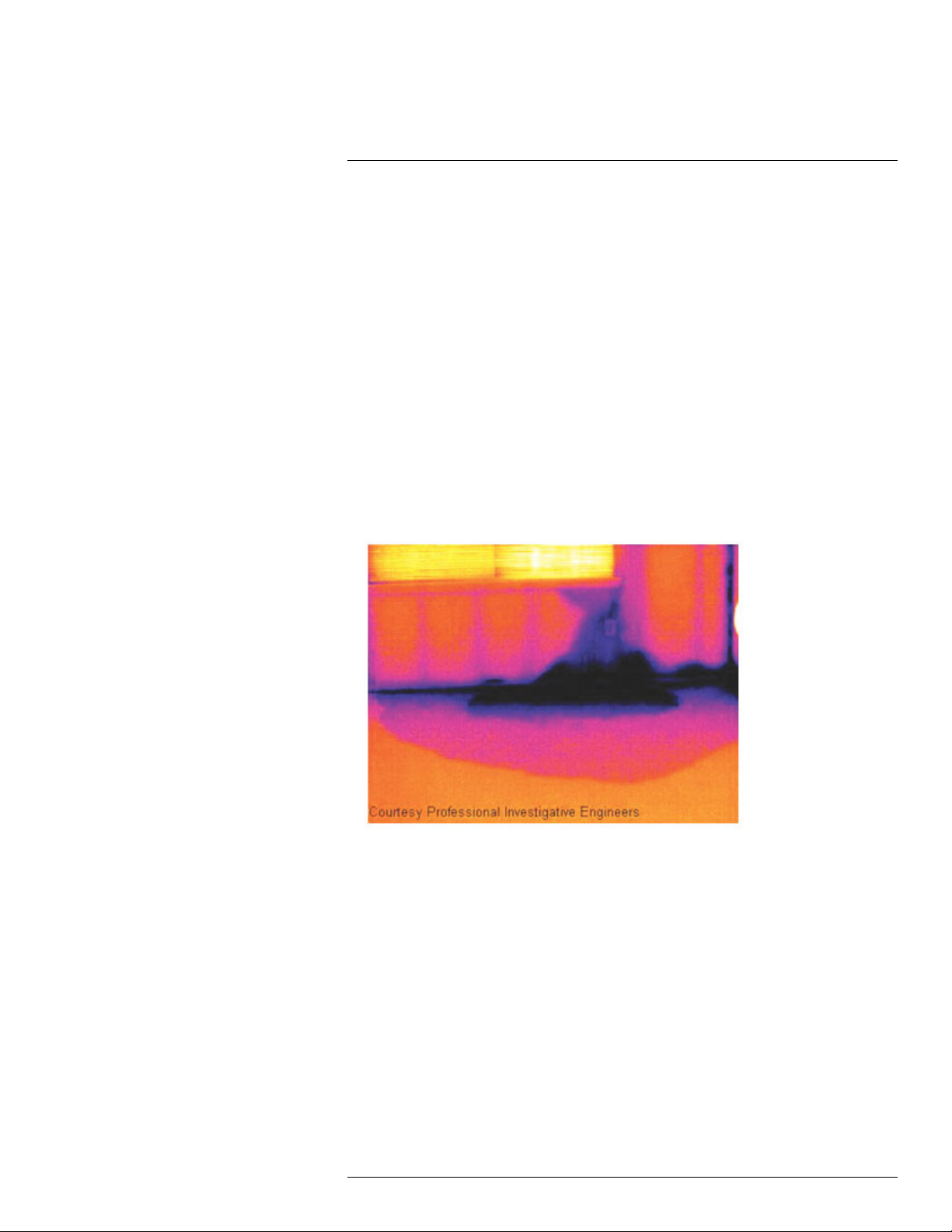
12
Application examples
12.1 Moisture & water damage
12.1.1 General
It is often possible to detect moisture and water damage in a house by using an infrared
camera. This is partly because the damaged area has a different heat conduction property
and partly because it has a different thermal capacity to store heat than the surrounding
material.
Many factors can come into play as to how moisture or water damage will appear in an infrared image.
For example, heating and cooling of these parts takes place at different rates depending
on the material and the time of day. For this reason, it is important that other methods are
used as well to check for moisture or water damage.
12.1.2 Figure
The image below shows extensive water damage on an external wall where the water has
penetrated the outer facing because of an incorrectly installed window ledge.
12.2 Faulty contact in socket
12.2.1 General
Depending on the type of connection a socket has, an improperly connected wire can result in local temperature increase. This temperature increase is caused by the reduced
contact area between the connection point of the incoming wire and the socket , and can
result in an electrical fire.
A socket’s construction may differ dramatically from one manufacturer to another. For this
reason, different faults in a socket can lead to the same typical appearance in an infrared
image.
Local temperature increase can also result from improper contact between wire and socket, or from difference in load.
#T559828; r. AN/55574/55574; en-US
86
Page 95
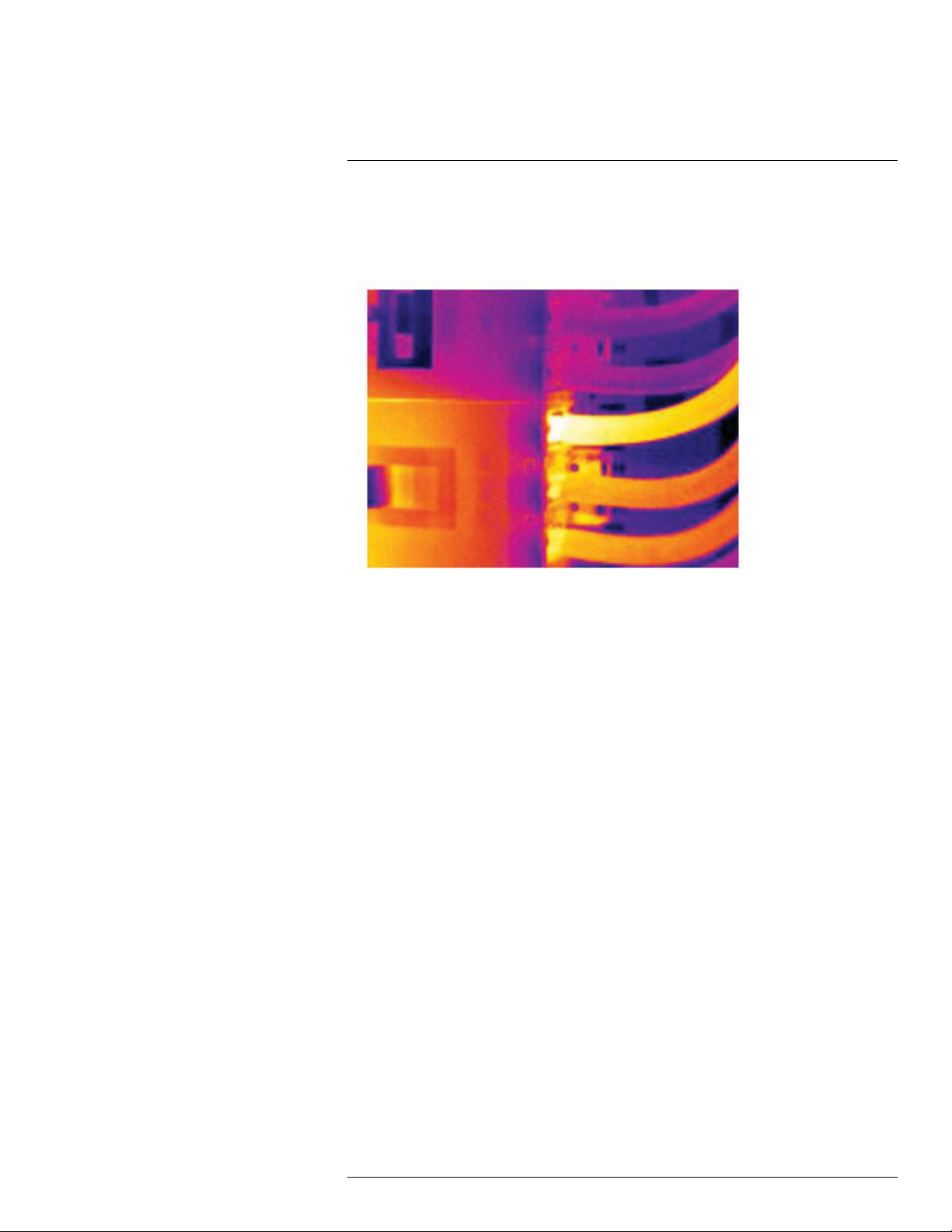
Application examples12
12.2.2 Figure
The image below shows a connection of a cable to a socket where improper contact in the
connection has resulted in local temperature increase.
12.3 Oxidized socket
12.3.1 General
Depending on the type of socket and the environment in which the socket is installed, oxides may occur on the socket's contact surfaces. These oxides can lead to locally increased resistance when the socket is loaded, which can be seen in an infrared image as
local temperature increase.
A socket’s construction may differ dramatically from one manufacturer to another. For this
reason, different faults in a socket can lead to the same typical appearance in an infrared
image.
Local temperature increase can also result from improper contact between a wire and
socket, or from difference in load.
12.3.2 Figure
The image below shows a series of fuses where one fuse has a raised temperature on the
contact surfaces against the fuse holder. Because of the fuse holder’s blank metal, the
temperature increase is not visible there, while it is visible on the fuse’s ceramic material.
#T559828; r. AN/55574/55574; en-US
87
Page 96

Application examples12
12.4 Insulation deficiencies
12.4.1 General
Insulation deficiencies may result from insulation losing volume over the course of time
and thereby not entirely filling the cavity in a frame wall.
An infrared camera allows you to see these insulation deficiencies because they either
have a different heat conduction property than sections with correctly installed insulation,
and/or show the area where air is penetrating the frame of the building.
When you are inspecting a building, the temperature difference between the inside and
outside should be at least 10°C (18°F). Studs, water pipes, concrete columns, and similar
components may resemble an insulation deficiency in an infrared image. Minor differences
may also occur naturally.
12.4.2 Figure
In the image below, insulation in the roof framing is lacking. Due to the absence of insulation, air has forced its way into the roof structure, which thus takes on a different characteristic appearance in the infrared image.
#T559828; r. AN/55574/55574; en-US
88
Page 97

Application examples12
12.5 Draft
12.5.1 General
Draft can be found under baseboards, around door and window casings, and above ceiling trim. This type of draft is often possible to see with an infrared camera, as a cooler airstream cools down the surrounding surface.
When you are investigating draft in a house, there should be sub-atmospheric pressure in
the house. Close all doors, windows, and ventilation ducts, and allow the kitchen fan to run
for a while before you take the infrared images.
An infrared image of draft often shows a typical stream pattern. You can see this stream
pattern clearly in the picture below.
Also keep in mind that drafts can be concealed by heat from floor heating circuits.
12.5.2 Figure
The image below shows a ceiling hatch where faulty installation has resulted in a strong
draft.
#T559828; r. AN/55574/55574; en-US
89
Page 98

Application examples12
#T559828; r. AN/55574/55574; en-US
90
Page 99

13
About FLIR Systems
FLIR Systems was established in 1978 to pioneer the development of high-performance
infrared imaging systems, and is the world leader in the design, manufacture, and marketing of thermal imaging systems for a wide variety of commercial, industrial, and government applications. Today, FLIR Systems embraces five major companies with outstanding
achievements in infrared technology since 1958—the Swedish AGEMA Infrared Systems
(formerly AGA Infrared Systems), the three United States companies Indigo Systems, FSI,
and Inframetrics, and the French company Cedip.
Since 2007, FLIR Systems has acquired several companies with world-leading expertise
in sensor technologies:
• Extech Instruments (2007)
• Ifara Tecnologías (2008)
• Salvador Imaging (2009)
• OmniTech Partners (2009)
• Directed Perception (2009)
• Raymarine (2010)
• ICx Technologies (2010)
• TackTick Marine Digital Instruments (2011)
• Aerius Photonics (2011)
• Lorex Technology (2012)
• Traficon (2012)
• MARSS (2013)
• DigitalOptics micro-optics business (2013)
• DVTEL (2015)
• Point Grey Research (2016)
• Prox Dynamics (2016)
Figure 13.1 Patent documents from the early 1960s
FLIR Systems has three manufacturing plants in the United States (Portland, OR, Boston,
MA, Santa Barbara, CA) and one in Sweden (Stockholm). Since 2007 there is also a
#T559828; r. AN/55574/55574; en-US
91
Page 100
13
About FLIR Systems
manufacturing plant in Tallinn, Estonia. Direct sales offices in Belgium, Brazil, China,
France, Germany, Great Britain, Hong Kong, Italy, Japan, Korea, Sweden, and the USA—
together with a worldwide network of agents and distributors—support our international
customer base.
FLIR Systems is at the forefront of innovation in the infrared camera industry. We anticipate market demand by constantly improving our existing cameras and developing new
ones. The company has set milestones in product design and development such as the introduction of the first battery-operated portable camera for industrial inspections, and the
first uncooled infrared camera, to mention just two innovations.
Figure 13.2 1969: Thermovision Model 661. The
camera weighed approximately 25 kg (55 lb.), the
oscilloscope 20 kg (44 lb.), and the tripod 15 kg
(33 lb.). The operator also needed a 220 VAC generator set, and a 10 L (2.6 US gallon) jar with liquid
nitrogen. To the left of the oscilloscope the Polaroid
attachment (6 kg (13 lb.)) can be seen.
Figure 13.3 2015: FLIR One, an accessory to
iPhone and Android mobile phones. Weight: 90 g
(3.2 oz.).
FLIR Systems manufactures all vital mechanical and electronic components of the camera
systems itself. From detector design and manufacturing, to lenses and system electronics,
to final testing and calibration, all production steps are carried out and supervised by our
own engineers. The in-depth expertise of these infrared specialists ensures the accuracy
and reliability of all vital components that are assembled into your infrared camera.
13.1 More than just an infrared camera
At FLIR Systems we recognize that our job is to go beyond just producing the best infrared
camera systems. We are committed to enabling all users of our infrared camera systems
to work more productively by providing them with the most powerful camera–software
combination. Especially tailored software for predictive maintenance, R & D, and process
monitoring is developed in-house. Most software is available in a wide variety of
languages.
We support all our infrared cameras with a wide variety of accessories to adapt your equipment to the most demanding infrared applications.
#T559828; r. AN/55574/55574; en-US
92
 Loading...