

Page 1
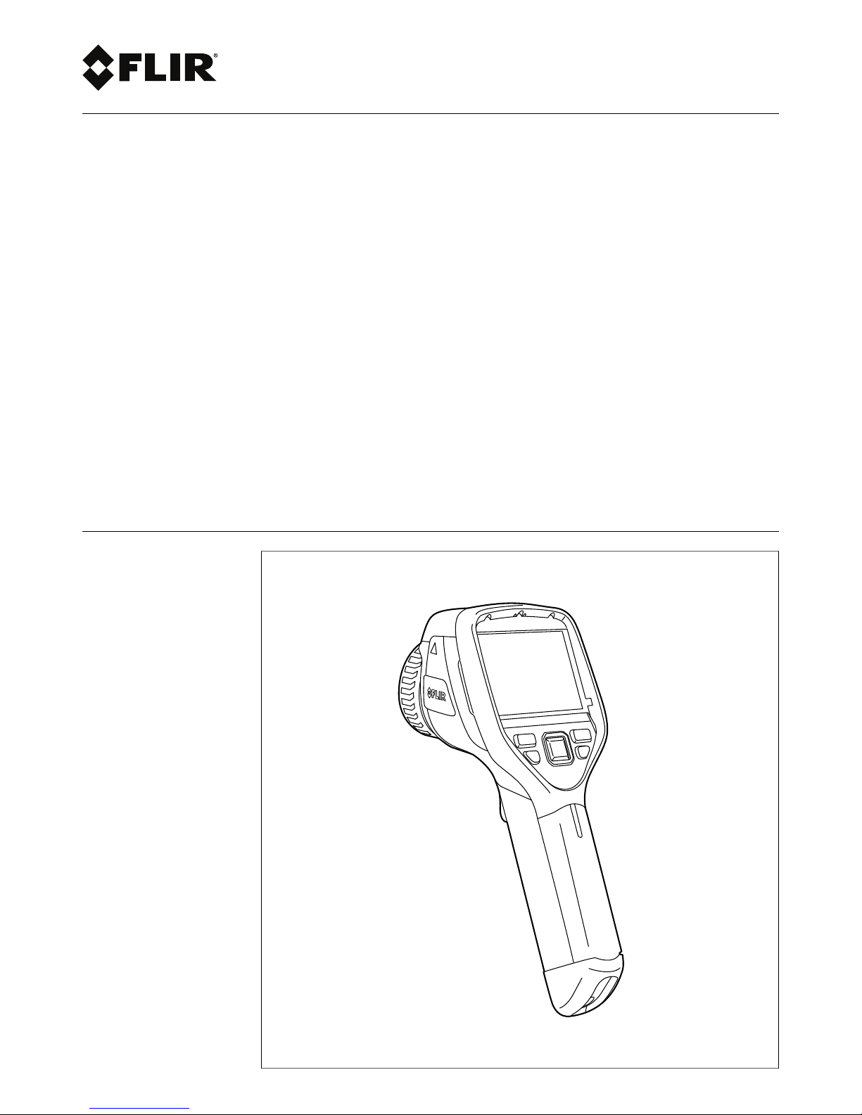
User’s manual
FLIR Exx series
Page 2

Page 3

User’s manual
FLIR Exx series
#T559845; r. AJ/37554/37554; en-US
iii
Page 4

Page 5

Table of contents
1 Disclaimers ............ .. .. .. ................................. .. .. .. ............................. 1
1.1 Legal disclaimer ....................................................................... 1
1.2 Usage statistics ........................................................................1
1.3 Changes to registry ................................................................... 1
1.4 U.S. Government Regulations...................................................... 1
1.5 Copyright ................................................................................1
1.6 Quality assurance .....................................................................1
1.7 Patents...................................................................................1
1.8 EULA Terms ............................................................................1
1.9 EULA Terms ............................................................................1
2 Safety information .......... .. .. .. ................................. .. .. .. ......................3
3 Notice to user ......... .. .. .. ................................. .. .. .. ............................. 7
3.1 User-to-user forums .................................................................. 7
3.2 Calibration...............................................................................7
3.3 Accuracy ................................................................................ 7
3.4 Disposal of electronic waste........................................................ 7
3.5 Training .................................................................................. 7
3.6 Documentation updates ............................................................. 7
3.7 Important note about this manual.................................................. 7
3.8 Note about authoritative versions..................................................7
4 Customer help .............. .. .. .. ............................... .. .. .. ......................... 8
4.1 General ..................................................................................8
4.2 Submitting a question ................................................................8
4.3 Downloads ..............................................................................9
5 Quick Start Guide ................. .. .. ................................. .. .. .. ................ 10
5.1 Procedure ............................................................................. 10
6 List of accessories and services .. .. .. ................................. .. .. .. .......... 11
7 Camera parts ............................... .. .. .. ................................. .. .. .. ...... 13
7.1 View from the right .................................................................. 13
7.1.1 Figure........................................................................ 13
7.1.2 Explanation................................................................. 13
7.2 View from the left .................................................................... 14
7.2.1 Figure........................................................................ 14
7.2.2 Explanation................................................................. 14
7.3 LCD and keypad..................................................................... 15
7.3.1 Figure........................................................................ 15
7.3.2 Explanation................................................................. 15
7.4 View from the bottom............................................................... 16
7.4.1 Figure........................................................................ 16
7.4.2 Explanation................................................................. 16
7.5 Battery condition LED indicator.................................................. 17
7.5.1 Figure........................................................................ 17
7.5.2 Explanation................................................................. 17
7.6 Laser pointer ......................................................................... 18
7.6.1 Figure........................................................................ 18
7.6.2 Laser warning label....................................................... 18
7.6.3 Laser rules and regulations ............................................ 18
8 Screen elements .... .. .. .. ................................. .. .. .............................. 19
8.1 Figure .................................................................................. 19
8.2 Explanation ........................................................................... 19
9 Navigating the menu system... .. .. .. ................................. .. .. .. ............. 20
9.1 Figure .................................................................................. 20
9.2 Explanation ........................................................................... 20
#T559845; r. AJ/37554/37554; en-US
v
Page 6

Table of contents
10 Connecting external devices and storage media . .. .............................. 21
10.1 Figure .................................................................................. 21
10.2 Explanation ........................................................................... 21
10.3 Figure .................................................................................. 22
10.4 Explanation ........................................................................... 22
11 Pairing Bluetooth devices.................. .. .. .. ................................. .. .. .. .. 23
11.1 General ................................................................................ 23
11.2 Procedure ............................................................................. 23
12 Configuring Wi-Fi .................. .. .. .. ................................. .. .. .. ............. 24
12.1 General ................................................................................ 24
12.2 Setting up a peer-to-peer connection (most common use) ............... 24
12.3 Connecting the camera to a wireless local area network (less
common use)......................................................................... 24
13 Handling the camera ... .. .. .. ................................. .. .. .. ........................ 25
13.1 Charging the battery................................................................ 25
13.1.1 Using the power supply to charge the battery ..................... 25
13.1.2 Using the stand-alone battery charger to charge the
battery ....................................................................... 25
13.2 Turning on and turning off the camera.......................................... 25
13.3 Adjusting the infrared camera focus ............................................ 26
13.3.1 Figure........................................................................ 26
13.3.2 Procedure .................................................................. 26
13.4 Operating the laser pointer........................................................ 27
13.4.1 Figure........................................................................ 27
13.4.2 Procedure .................................................................. 27
13.5 Removing the battery............................................................... 27
13.6 Mounting an accessory lens ...................................................... 28
13.7 Calibrating the touchscreen....................................................... 29
13.7.1 Figure........................................................................ 29
13.7.2 Procedure .................................................................. 29
13.8 Using the camera lamp ............................................................ 29
13.8.1 General...................................................................... 29
13.8.2 Procedure .................................................................. 30
14 Working with images............. .. .. ................................. .. .. .. ................ 31
14.1 Saving an image ..................................................................... 31
14.1.1 General...................................................................... 31
14.1.2 Image capacity ............................................................ 31
14.1.3 Naming convention....................................................... 31
14.1.4 Procedure .................................................................. 31
14.2 Previewing an image ............................................................... 31
14.2.1 General...................................................................... 31
14.2.2 Procedure .................................................................. 31
14.3 Opening a saved image............................................................ 32
14.3.1 General...................................................................... 32
14.3.2 Procedure .................................................................. 32
14.4 Editing a saved image.............................................................. 32
14.4.1 General...................................................................... 32
14.4.2 Procedure .................................................................. 32
14.5 Adjusting an infrared image....................................................... 32
14.5.1 General...................................................................... 32
14.5.2 Example 1 .................................................................. 33
14.5.3 Example 2 .................................................................. 33
14.5.4 Manual adjustment in Level / span mode ........................... 33
14.5.5 Manual adjustment in Level / max / min mode ..................... 34
14.6 Performing a non-uniformity correction (NUC) ............................... 34
#T559845; r. AJ/37554/37554; en-US
vi
Page 7

Table of contents
14.6.1 What is a non-uniformity correction?................................. 34
14.6.2 When to perform a non-uniformity correction? .................... 34
14.6.3 Procedure .................................................................. 34
14.7 Changing the temperature range ................................................ 34
14.7.1 General...................................................................... 34
14.7.2 Procedure .................................................................. 34
14.8 Changing the color palette ........................................................ 35
14.8.1 General...................................................................... 35
14.8.2 Procedure .................................................................. 35
14.9 Zooming in on an image ........................................................... 35
14.9.1 General...................................................................... 35
14.9.2 Procedure .................................................................. 35
14.10 Deleting an image................................................................... 35
14.10.1 Procedure .................................................................. 35
14.11 Deleting all images.................................................................. 36
14.11.1 Procedure .................................................................. 36
15 Working with image modes ............................. .. .. .............................. 37
15.1 General ................................................................................ 37
15.2 Types of image modes ............................................................. 37
15.3 Procedure ............................................................................. 38
16 Working with measurement tools .. .. .. ................................. .. .. .. ......... 39
16.1 Laying out measurement tools in live mode................................... 39
16.1.1 General...................................................................... 39
16.1.2 Procedure .................................................................. 39
16.2 Laying out measurement tools in edit mode .................................. 39
16.2.1 General...................................................................... 39
16.2.2 Procedure .................................................................. 39
16.3 Moving and resizing measurement tools ...................................... 40
16.3.1 General...................................................................... 40
16.3.2 Procedure .................................................................. 40
16.4 Displaying maximum, minimum, and average values....................... 40
16.4.1 General...................................................................... 40
16.4.2 Procedure .................................................................. 40
16.5 Setting local measurement parameters for a measurement
tool ...................................................................................... 41
16.5.1 General...................................................................... 41
16.5.2 Procedure .................................................................. 41
17 Working with alarms ... .. .. .. ................................. .. .. .. ........................ 42
17.1 Working with color alarms ......................................................... 42
17.1.1 General...................................................................... 42
17.1.2 Procedure .................................................................. 42
17.2 Working with insulation alarms ................................................... 42
17.2.1 General...................................................................... 42
17.2.2 Procedure .................................................................. 42
17.3 Working with condensation alarms.............................................. 43
17.3.1 General...................................................................... 43
17.3.2 Procedure .................................................................. 43
18 Fetching data from external FLIR meters .................. .. ........................ 44
18.1 General ................................................................................ 44
18.2 Supported meters ................................................................... 44
18.3 Technical support for external meters .......................................... 44
18.4 Procedure ............................................................................. 44
18.5 Typical moisture measurement and documentation
procedure ............................................................................. 44
18.5.1 General...................................................................... 44
#T559845; r. AJ/37554/37554; en-US
vii
Page 8

Table of contents
18.5.2 Procedure .................................................................. 44
19 Annotating images ........ .. .. .. ............................... .. .. .. ....................... 45
19.1 General ................................................................................ 45
19.2 Adding a note ........................................................................ 45
19.2.1 General...................................................................... 45
19.2.2 Procedure .................................................................. 45
19.3 Adding a table ........................................................................ 45
19.3.1 General...................................................................... 45
19.3.2 Procedure .................................................................. 46
19.4 Adding a voice annotation......................................................... 46
19.4.1 General...................................................................... 46
19.4.2 Procedure .................................................................. 46
20 Recording video clips ............ .. .. .. ................................. .. .. .. ............. 47
20.1 General ................................................................................ 47
20.2 Procedure: Recording a video clip .............................................. 47
20.3 Procedure: Playing a video clip .................................................. 47
21 Screening alarm . ................................. .. .. .. ................................. .. .. . 48
21.1 General ................................................................................ 48
21.2 Procedure ............................................................................. 48
22 Changing settings . .. .. ................................. .. .. .. ............................... 49
22.1 General ................................................................................ 49
22.2 Procedure ............................................................................. 49
22.3 Description of the various settings .............................................. 49
22.3.1 Measurement parameters .............................................. 49
22.3.2 Save options ............................................................... 50
22.3.3 Add-on lens ................................................................ 50
22.3.4 Device settings............................................................ 50
23 Technical data ......... .. .. .. ................................. .. .. .. ........................... 52
23.1 Online field-of-view calculator .................................................... 52
23.2 Note about technical data ......................................................... 52
23.3 Note about authoritative versions................................................ 52
23.4 FLIR E33 .............................................................................. 53
23.5 FLIR E40 .............................................................................. 58
23.6 FLIR E40 (incl. Wi-Fi)............................................................... 63
23.7 FLIR E40 with SC kit (incl. Wi-Fi and 45° lens)............................... 68
23.8 FLIR E40 with SC kit (incl. Wi-Fi)................................................ 73
23.9 FLIR E40bx (incl. Wi-Fi) ........................................................... 78
23.10 FLIR E50 .............................................................................. 83
23.11 FLIR E50 (incl. Wi-Fi)............................................................... 88
23.12 FLIR E50bx (incl. Wi-Fi) ........................................................... 93
23.13 FLIR E60 .............................................................................. 98
23.14 FLIR E60 (incl. Wi-Fi)............................................................. 103
23.15 FLIR E60 with Educational kit (DE) ........................................... 108
23.16 FLIR E60 with Educational kit (EN) ........................................... 109
23.17 FLIR E60 with Educational kit (ES)............................................ 110
23.18 FLIR E60 with Educational kit (FR)............................................ 111
23.19 FLIR E60 with Educational kit (IT) ............................................. 112
23.20 FLIR E60 with Educational kit (JA) ............................................ 113
23.21 FLIR E60 with Educational kit (KO) ........................................... 114
23.22 FLIR E60bx (incl. Wi-Fi) ......................................................... 115
23.23 FLIR E63 (incl. Wi-Fi)............................................................. 120
#T559845; r. AJ/37554/37554; en-US
viii
Page 9

Table of contents
24 Mechanical drawings .. .. .. .. ................................. .. .. .. ...................... 125
25 CE Declaration of conformity ............ .. .. .. ................................. .. .. ... 130
26 Cleaning the camera.......... .. .. .. ................................. .. .. .. ............... 132
26.1 Camera housing, cables, and other items................................... 132
26.1.1 Liquids..................................................................... 132
26.1.2 Equipment................................................................ 132
26.1.3 Procedure ................................................................ 132
26.2 Infrared lens ........................................................................ 132
26.2.1 Liquids..................................................................... 132
26.2.2 Equipment................................................................ 132
26.2.3 Procedure ................................................................ 132
27 Application examples.. .. ................................. .. .. ............................ 133
27.1 Moisture & water damage ....................................................... 133
27.1.1 General.................................................................... 133
27.1.2 Figure...................................................................... 133
27.2 Faulty contact in socket .......................................................... 133
27.2.1 General.................................................................... 133
27.2.2 Figure...................................................................... 133
27.3 Oxidized socket.................................................................... 134
27.3.1 General.................................................................... 134
27.3.2 Figure...................................................................... 134
27.4 Insulation deficiencies............................................................ 135
27.4.1 General.................................................................... 135
27.4.2 Figure...................................................................... 135
27.5 Draft .................................................................................. 135
27.5.1 General.................................................................... 135
27.5.2 Figure...................................................................... 135
28 About FLIR Systems .................. .. .. .. ................................. .. .. .. ....... 137
28.1 More than just an infrared camera ............................................ 138
28.2 Sharing our knowledge .......................................................... 138
28.3 Supporting our customers....................................................... 138
29 Glossary .... ..................................... .. ..................................... .. .... 140
30 Thermographic measurement techniques .............................. .. .. .. .... 143
30.1 Introduction ........................................................................ 143
30.2 Emissivity............................................................................ 143
30.2.1 Finding the emissivity of a sample .................................. 143
30.3 Reflected apparent temperature ............................................... 146
30.4 Distance ............................................................................. 147
30.5 Relative humidity .................................................................. 147
30.6 Other parameters.................................................................. 147
31 History of infrared technology................................. .. .. .. .................. 148
32 Theory of thermography ................................. .. .. ............................ 151
32.1 Introduction ......................................................................... 151
32.2 The electromagnetic spectrum................................................. 151
32.3 Blackbody radiation............................................................... 151
32.3.1 Planck’s law .............................................................. 152
32.3.2 Wien’s displacement law.............................................. 153
32.3.3 Stefan-Boltzmann's law ............................................... 154
32.3.4 Non-blackbody emitters............................................... 155
32.4 Infrared semi-transparent materials........................................... 157
33 The measurement formula....................... .. .. .. ............................... .. 158
34 Emissivity tables .. .. ................................. .. .. .. ................................ 162
34.1 References.......................................................................... 162
34.2 Tables ................................................................................ 162
#T559845; r. AJ/37554/37554; en-US
ix
Page 10

Page 11

Disclaimers
1
1.1 Legal disclaimer
All products manufactured by FLIR Systems are warranted against defective
materials and workmanship for a period of one (1) year from the delivery date
of the original purchase, provided such products have been under normal
storage, use and service, and in accordance with FLIR Systems instruction.
Uncooled handheld infrared cameras manufactured by FLIR Systemsare
warranted against defective materials andworkmanship for a period of two
(2) years from the delivery date of theoriginal purchase, provided such products have been under normalstorage, use and service, and in accordance
with FLIR Systems instruction, and provided that thecamera has been registered within 60 days of original purchase.
Detectors for uncooled handheld infrared cameras manufactured byFLIR
Systems are warranted against defective materials and workmanship for a
period of ten (10) years from the deliverydate of the original purchase, provided such products have been under normal storage,use and service, and
in accordance with FLIR Systems instruction, and providedthat the camera
has been registered within 60 days of original purchase.
Products which are not manufactured by FLIR Systems but included in systems delivered by FLIR Systems to the originalpurchaser, carry the warranty,
if any, of the particular supplieronly. FLIR Systems has no responsibility
whatsoever for such products.
The warranty extends only to the original purchaser andis not transferable. It
is not applicable to any product which has been subjected to misuse, neglect,
accident or abnormal conditions of operation. Expendable partsare excluded
from the warranty.
In the case of a defect in aproduct covered by this warranty the product must
not be further used in order to prevent additional damage. The purchaser
shall promptly report any defect to FLIR Systemsor thiswarranty will not
apply.
FLIR Systems will, at its option, repair orreplace any such defective product
free of charge if, upon inspection, it proves to bedefective in materialor workmanship and provided that it is returned toFLIR Systemswithin the said oneyear period.
FLIR Systems has no other obligation or liabilityfor defects than those set
forth above.
No other warranty is expressed or implied. FLIR Systems specifically disclaims the implied warranties of merchantability and fitness for a particular
purpose.
FLIR Systems shall not be liable for any direct, indirect, special, incidental or
consequential loss or damage, whether based on contract,tort orany other
legal theory.
This warranty shall be governed by Swedish law.
Any dispute, controversy or claim arisingout ofor in connection with this war-
ranty, shall be finally settled by arbitration in accordance with the Rules of the
Arbitration Institute of the StockholmChamber of Commerce. The place of arbitration shall be Stockholm. The language to be used in thearbitral proceedings shall be English.
1.2 Usage statistics
FLIR Systems reserves the right to gather anonymous usage statistics to help
maintain and improve the quality of our software and services.
1.3 Changes to registry
The registry entry HKEY_LOCAL_MACHINE\SYSTEM\CurrentControlSet
\Control\Lsa\LmCompatibilityLevel will be automatically changed to level 2 if
the FLIR Camera Monitor service detects a FLIR camera connected to the
computer with a USB cable. The modification will only be executed if the
camera device implements a remote network service thatsupports network
logons.
1.4 U.S. Government Regulations
This product may be subject to U.S. Export Regulations.Please send any inquiries to exportquestions@flir.com.
1.5 Copyright
© 2016, FLIR Systems, Inc. All rights reservedworldwide. No parts of the
software including source code may be reproduced, transmitted, transcribed
or translated into anylanguage or computer language in any form or by any
means, electronic, magnetic, optical, manualor otherwise,without the prior
written permission of FLIR Systems.
The documentation must not, in whole or part, be copied, photocopied,reproduced, translated or transmittedto any electronic medium or machine
readable form without prior consent, in writing, from FLIR Systems.
Names and marks appearing on the products herein are either registered
trademarks or trademarks ofFLIR Systems and/or its subsidiaries. Allother
trademarks, trade names or company names referenced herein are used for
identification only and are the property of theirrespective owners.
1.6 Quality assurance
The Quality Management System under which these products are developed
and manufactured has been certified in accordance with the ISO 9001
standard.
FLIR Systems is committed to a policy of continuous development; therefore
we reserve the right to make changes andimprovements on any of the products without prior notice.
1.7 Patents
One or several of thefollowing patents and/or design patents may apply to
the products and/or features. Additional pending patents and/orpending design patents may also apply.
000279476-0001; 000439161; 000499579-0001; 000653423; 000726344;
000859020; 001106306-0001; 001707738; 001707746; 001707787;
001776519; 001954074; 002021543; 002058180; 002249953; 002531178;
0600574-8; 1144833; 1182246; 1182620; 1285345; 1299699; 1325808;
1336775; 1391114; 1402918; 1404291; 1411581; 1415075; 1421497;
1458284; 1678485; 1732314; 2106017; 2107799; 2381417; 3006596;
3006597; 466540; 483782; 484155; 4889913; 5177595; 60122153.2;
602004011681.5-08; 6707044; 68657; 7034300; 7110035; 7154093;
7157705; 7237946; 7312822; 7332716; 7336823; 7544944; 7667198;
7809258 B2; 7826736; 8,153,971; 8,823,803; 8,853,631; 8018649 B2;
8212210 B2; 8289372; 8354639 B2; 8384783; 8520970; 8565547; 8595689;
8599262; 8654239; 8680468; 8803093; D540838; D549758; D579475;
D584755; D599,392; D615,113; D664,580; D664,581; D665,004; D665,440;
D677298; D710,424 S; D718801; DI6702302-9; DI6903617-9; DI7002221-6;
DI7002891-5; DI7002892-3; DI7005799-0; DM/057692; DM/061609; EP
2115696 B1; EP2315433; SE 0700240-5; US 8340414 B2; ZL
201330267619.5; ZL01823221.3; ZL01823226.4; ZL02331553.9;
ZL02331554.7; ZL200480034894.0; ZL200530120994.2;
ZL200610088759.5; ZL200630130114.4; ZL200730151141.4;
ZL200730339504.7; ZL200820105768.8; ZL200830128581.2;
ZL200880105236.4; ZL200880105769.2; ZL200930190061.9;
ZL201030176127.1; ZL201030176130.3; ZL201030176157.2;
ZL201030595931.3; ZL201130442354.9; ZL201230471744.3;
ZL201230620731.8.
1.8 EULA Terms
• Youhave acquired a device (“INFRARED CAMERA”) that includes software licensed by FLIR SystemsAB from Microsoft Licensing, GP or its
affiliates (“MS”). Those installed software products of MSorigin, as well
as associated media, printed materials, and “online” orelectronic documentation (“SOFTWARE”) are protected by international intellectual
property laws and treaties. The SOFTWARE is licensed, notsold. All
rights reserved.
• IF YOU DO NOT AGREE TO THIS END USERLICENSE AGREEMENT
(“EULA”), DO NOT USE THE DEVICE OR COPY THE SOFTWARE. INSTEAD, PROMPTLY CONTACT FLIR Systems AB FOR INSTRUCTIONS ON RETURN OF THE UNUSED DEVICE(S) FOR A REFUND.
ANY USE OF THE SOFTWARE, INCLUDING BUT NOT LIMITED TO
USE ON THE DEVICE, WILL CONSTITUTE YOUR AGREEMENT TO
THIS EULA (OR RATIFICATION OF ANY PREVIOUS CONSENT).
• GRANT OF SOFTWARE LICENSE. This EULAgrants youthe following
license:
◦ Youmay use the SOFTWARE only on theDEVICE.
◦ NOT FAULT TOLERANT. THE SOFTWARE IS NOT FAULT TOL-
ERANT.FLIR SystemsAB HAS INDEPENDENTLYDETERMINED
HOW TO USE THE SOFTWARE IN THEDEVICE, AND MS HAS
RELIED UPON FLIR Systems AB TO CONDUCT SUFFICIENT
TESTING TO DETERMINE THAT THE SOFTWARE IS SUITABLE
FOR SUCH USE.
◦ NO WARRANTIES FOR THE SOFTWARE. THE SOFTWARE is
provided “AS IS” and with allfaults. THE ENTIRE RISK AS TO
SATISFACTORY QUALITY, PERFORMANCE, ACCURACY, AND
EFFORT (INCLUDING LACK OF NEGLIGENCE) IS WITH YOU.
ALSO, THERE IS NO WARRANTY AGAINST INTERFERENCE
WITH YOUR ENJOYMENT OF THE SOFTWARE OR AGAINST
INFRINGEMENT.IF YOU HAVE RECEIVED ANY WARRANTIES
REGARDING THE DEVICE OR THE SOFTWARE, THOSE WARRANTIES DO NOT ORIGINATE FROM, AND ARE NOT BINDING
ON, MS.
◦ No Liability for Certain Damages. EXCEPT AS PROHIBITED BY
LAW,MS SHALLHAVE NO LIABILITY FOR ANY INDIRECT,
SPECIAL, CONSEQUENTIAL OR INCIDENTALDAMAGES
ARISING FROM OR IN CONNECTION WITH THE USEOR PERFORMANCE OF THE SOFTWARE. THIS LIMITATION SHALL
APPLYEVEN IF ANY REMEDY FAILS OF ITS ESSENTIAL PURPOSE. IN NO EVENT SHALL MS BE LIABLEFOR ANY
AMOUNT IN EXCESS OF U.S. TWO HUNDRED FIFTY DOLLARS (U.S.$250.00).
◦ Limitations on Reverse Engineering, Decompilation, and Dis-
assembly. You may not reverse engineer, decompile, or disas-
semble the SOFTWARE, except and onlyto the extent that such
activity is expressly permitted byapplicable law notwithstanding
this limitation.
◦ SOFTWARE TRANSFER ALLOWED BUT WITH RESTRIC-
TIONS. You may permanently transfer rights under this EULA only
as part of a permanent sale or transfer of the Device, and only if
the recipient agrees to this EULA. If the SOFTWARE is an upgrade, any transfer must alsoinclude allprior versionsof the
SOFTWARE.
◦ EXPORT RESTRICTIONS. You acknowledge that SOFTWARE is
subject to U.S. export jurisdiction. You agree to comply with allapplicable international and national laws that apply tothe SOFTWARE, including the U.S. Export AdministrationRegulations, as
well as end-user, end-use and destination restrictions issued by U.
S. and other governments. For additional information see http://
www.microsoft.com/exporting/.
1.9 EULA Terms
Qt4 Core and Qt4 GUI, Copyright ©2013 NokiaCorporation and FLIR Systems AB. This Qt library is a free software; you can redistributeit and/ormodify it under the terms of the GNU Lesser General PublicLicense as published
by the Free Software Foundation; either version 2.1 of the License, or (atyour
option) any later version. This library is distributed in the hope that it willbe
useful, but WITHOUT ANY WARRANTY; without even the implied warranty of
MERCHANTABILITYor FITNESS FOR APARTICULAR PURPOSE. See the
GNU Lesser General Public License, http://www.gnu.org/licenses/lgpl-2.1.
#T559845; r. AJ/37554/37554; en-US
1
Page 12

Disclaimers1
html. The source code for the libraries Qt4 Core and Qt4GUI may be requested from FLIR Systems AB.
#T559845; r. AJ/37554/37554; en-US
2
Page 13

Safety information
2
WARNING
Applicability: Class B digital devices.
This equipment has been tested and found to comply with the limits for a Class B digital device, pursuant to Part 15 of the FCC Rules. These limits are designed to provide reasonable protection against
harmful interference in a residential installation. This equipment generates, uses and can radiate radio
frequency energy and, if not installed and used in accordance with the instructions, may cause harmful
interference to radio communications. However, there is no guarantee that interference will not occur in
a particular installation. If this equipment does cause harmful interference to radio or television reception, which can be determined by turning the equipment off and on, the user is encouraged to try to correct the interference by one or more of the following measures:
• Reorient or relocate the receiving antenna.
• Increase the separation between the equipment and receiver.
• Connect the equipment into an outlet on a circuit different from that to which the receiver is
connected.
• Consult the dealer or an experienced radio/TV technician for help.
WARNING
Applicability: Digital devices subject to 15.19/RSS-210.
NOTICE: This device complies with Part 15 of the FCC Rules and with RSS-210 of Industry Canada.
Operation is subject to the following two conditions:
1. this device may not cause harmful interference, and
2. this device must accept any interference received, including interference that may cause undesired
operation.
WARNING
Applicability: Digital devices subject to 15.21.
NOTICE: Changes or modifications made to this equipment not expressly approved by FLIR Systems
may void the FCC authorization to operate this equipment.
WARNING
Applicability: Digital devices subject to 2.1091/2.1093/OET Bulletin 65.
Radiofrequency radiation exposure Information: The radiated output power of the device is below
the FCC/IC radio frequency exposure limits. Nevertheless, the device shall be used in such a manner
that the potential for human contact during normal operation is minimized.
WARNING
Applicability: Cameras with one or more laser pointers.
Do not look directly into the laser beam. The laser beam can cause eye irritation.
WARNING
Applicability: Cameras with one or more batteries.
Do not disassemble or do a modification to the battery. The battery contains safety and protection devices which, if damage occurs, can cause the battery to become hot, or cause an explosion or an ignition.
WARNING
Applicability: Cameras with one or more batteries.
If there is a leak from the battery and you get the fluid in your eyes, do not rub your eyes. Flush well with
water and immediately get medical care. The battery fluid can cause injury to your eyes if you do not do
this.
#T559845; r. AJ/37554/37554; en-US
3
Page 14

Safety information
2
WARNING
Applicability: Cameras with one or more batteries.
Do not continue to charge the battery if it does not become charged in the specified charging time. If
you continue to charge the battery, it can become hot and cause an explosion or ignition. Injury to persons can occur.
WARNING
Applicability: Cameras with one or more batteries.
Only use the correct equipment to remove the electrical power from the battery. If you do not use the
correct equipment, you can decrease the performance or the life cycle of the battery. If you do not use
the correct equipment, an incorrect flow of current to the battery can occur. This can cause the battery
to become hot, or cause an explosion. Injury to persons can occur.
WARNING
Make sure that you read all applicable MSDS (Material Safety Data Sheets) and warning labels on containers before you use a liquid. The liquids can be dangerous. Injury to persons can occur.
CAUTION
Do not point the infrared camera (with or without the lens cover) at strong energy sources, for example,
devices that cause laser radiation, or the sun. This can have an unwanted effect on the accuracy of the
camera. It can also cause damage to the detector in the camera.
CAUTION
Do not use the camera in temperatures more than +50°C (+122°F), unless other information is specified
in the user documentation or technical data. High temperatures can cause damage to the camera.
CAUTION
Applicability: Cameras with one or more laser pointers.
To prevent damage, put the protective cap on the laser pointer when you do not operate the laser
pointer. Damage to the laser pointer can occur if you do not do this.
CAUTION
Applicability: Cameras with one or more batteries.
Do not attach the batteries directly to a car’s cigarette lighter socket, unless FLIR Systems supplies a
specific adapter to connect the batteries to a cigarette lighter socket. Damage to the batteries can
occur.
CAUTION
Applicability: Cameras with one or more batteries.
Do not connect the positive terminal and the negative terminal of the battery to each other with a metal
object (such as wire). Damage to the batteries can occur.
CAUTION
Applicability: Cameras with one or more batteries.
Do not get water or salt water on the battery, or permit the battery to become wet. Damage to the batteries can occur.
CAUTION
Applicability: Cameras with one or more batteries.
Do not make holes in the battery with objects. Damage to the battery can occur.
#T559845; r. AJ/37554/37554; en-US
4
Page 15

Safety information
2
CAUTION
Applicability: Cameras with one or more batteries.
Do not hit the battery with a hammer. Damage to the battery can occur.
CAUTION
Applicability: Cameras with one or more batteries.
Do not put your foot on the battery, hit it or cause shocks to it. Damage to the battery can occur.
CAUTION
Applicability: Cameras with one or more batteries.
Do not put the batteries in or near a fire, or into direct sunlight. When the battery becomes hot, the builtin safety equipment becomes energized and can stop the battery charging procedure. If the battery becomes hot, damage can occur to the safety equipment and this can cause more heat, damage or ignition of the battery.
CAUTION
Applicability: Cameras with one or more batteries.
Do not put the battery on a fire or increase the temperature of the battery with heat. Damage to the battery and injury to persons can occur.
CAUTION
Applicability: Cameras with one or more batteries.
Do not put the battery on or near fires, stoves, or other high-temperature locations. Damage to the battery and injury to persons can occur.
CAUTION
Applicability: Cameras with one or more batteries.
Do not solder directly onto the battery. Damage to the battery can occur.
CAUTION
Applicability: Cameras with one or more batteries.
Do not use the battery if, when you use, charge, or put the battery in storage, there is an unusual smell
from the battery, the battery feels hot, changes color, changes shape, or is in an unusual condition.
Speak with your sales office if one or more of these problems occurs. Damage to the battery and injury
to persons can occur.
CAUTION
Applicability: Cameras with one or more batteries.
Only use a specified battery charger when you charge the battery. Damage to the battery can occur if
you do not do this.
CAUTION
Applicability: Cameras with one or more batteries.
Only use a specified battery for the camera. Damage to the camera and the battery can occur if you do
not do this.
CAUTION
Applicability: Cameras with one or more batteries.
The temperature range through which you can charge the battery is ±0°C to +45°C (+32°F to +113°F),
unless other information is specified in the user documentation or technical data. If you charge the battery at temperatures out of this range, it can cause the battery to become hot or to break. It can also decrease the performance or the life cycle of the battery.
#T559845; r. AJ/37554/37554; en-US
5
Page 16

Safety information
2
CAUTION
Applicability: Cameras with one or more batteries.
The temperature range through which you can remove the electrical power from the battery is -15°C to
+50°C (+5°F to +122°F), unless other information is specified in the user documentation or technical
data. If you operate the battery out of this temperature range, it can decrease the performance or the life
cycle of the battery.
CAUTION
Applicability: Cameras with one or more batteries.
When the battery is worn, apply insulation to the terminals with adhesive tape or equivalent materials
before you discard it. Damage to the battery and injury to persons can occur if you do not do this.
CAUTION
Applicability: Cameras with one or more batteries.
Remove any water or moisture on the battery before you install it. Damage to the battery can occur if
you do not do this.
CAUTION
Do not apply solvents or equivalent liquids to the camera, the cables, or other items. Damage to the battery and injury to persons can occur.
CAUTION
Be careful when you clean the infrared lens. The lens has an anti-reflective coating which is easily damaged. Damage to the infrared lens can occur.
CAUTION
Do not use too much force to clean the infrared lens. This can cause damage to the anti-reflective
coating.
Note The encapsulation rating is only applicable when all the openings on the camera
are sealed with their correct covers, hatches, or caps. This includes the compartments
for data storage, batteries, and connectors.
#T559845; r. AJ/37554/37554; en-US
6
Page 17

Notice to user
3
3.1 User-to-user forums
Exchange ideas, problems, and infrared solutions with fellow thermographers around the
world in our user-to-user forums. To go to the forums, visit:
http://www.infraredtraining.com/community/boards/
3.2 Calibration
We recommend that you send in the camera for calibration once a year. Contact your local sales office for instructions on where to send the camera.
3.3 Accuracy
For very accurate results, we recommend that you wait 5 minutes after you have started
the camera before measuring a temperature.
3.4 Disposal of electronic waste
As with most electronic products, this equipment must be disposed of in an environmentally friendly way, and in accordance with existing regulations for electronic waste.
Please contact your FLIR Systems representative for more details.
3.5 Training
To read about infrared training, visit:
• http://www.infraredtraining.com
• http://www.irtraining.com
• http://www.irtraining.eu
3.6 Documentation updates
Our manuals are updated several times per year, and we also issue product-critical notifications of changes on a regular basis.
To access the latest manuals, translations of manuals, and notifications, go to the Download tab at:
http://support.flir.com
It only takes a few minutes to register online. In the download area you will also find the
latest releases of manuals for our other products, as well as manuals for our historical
and obsolete products.
3.7 Important note about this manual
FLIR Systems issues generic manuals that cover several cameras within a model line.
This means that this manual may contain descriptions and explanations that do not apply
to your particular camera model.
3.8 Note about authoritative versions
The authoritative version of this publication is English. In the event of divergences due to
translation errors, the English text has precedence.
Any late changes are first implemented in English.
#T559845; r. AJ/37554/37554; en-US
7
Page 18
Customer help
4
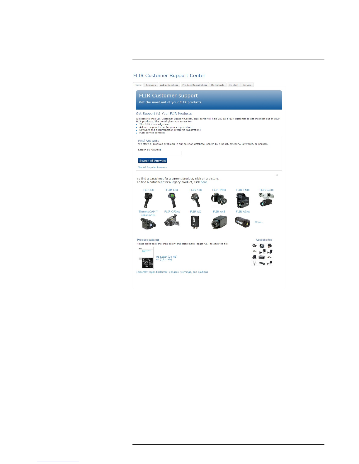
4.1 General
For customer help, visit:
http://support.flir.com
4.2 Submitting a question
To submit a question to the customer help team, you must be a registered user. It only
takes a few minutes to register online. If you only want to search the knowledgebase for
existing questions and answers, you do not need to be a registered user.
When you want to submit a question, make sure that you have the following information
to hand:
• The camera model
• The camera serial number
• The communication protocol, or method, between the camera and your device (for example, HDMI, Ethernet, USB, or FireWire)
• Device type (PC/Mac/iPhone/iPad/Android device, etc.)
• Version of any programs from FLIR Systems
• Full name, publication number, and revision number of the manual
#T559845; r. AJ/37554/37554; en-US
8
Page 19

Customer help
4
4.3 Downloads
On the customer help site you can also download the following, when applicable for the
product:
• Firmware updates for your infrared camera.
• Program updates for your PC/Mac software.
• Freeware and evaluation versions of PC/Mac software.
• User documentation for current, obsolete, and historical products.
• Mechanical drawings (in *.dxf and *.pdf format).
• Cad data models (in *.stp format).
• Application stories.
• Technical datasheets.
• Product catalogs.
#T559845; r. AJ/37554/37554; en-US
9
Page 20

Quick Start Guide
5
5.1 Procedure
Follow this procedure:
1. Put a battery into the battery compartment.
2. Charge the battery for 4 hours before starting the camera for the first time, or until the
green battery condition LED glows continuously.
3. Insert a memory card into the card slot.
4. Push
to turn on the camera.
5. Aim the camera toward the object of interest.
6. Adjust the focus by rotating the focus ring.
Note It is very important to adjust the focus correctly. Incorrect focus adjustment affects how the image modes Thermal MSX, Thermal, and Picture-in-picture work. It also affects the temperature measurement.
7. Push the Save button (the trigger) to save an image.
8. Install FLIR Tools on your computer.
9. Start FLIR Tools.
10. Connect the camera to the computer using the USB cable.
11. Import the images into FLIR Tools and create a PDF report.
#T559845; r. AJ/37554/37554; en-US
10
Page 21

List of accessories and services
6
Product name Part number
Battery charger, incl. power supply with multi
plugs (Exx, Kxx)
T198125
Bluetooth Headset
T197771ACC
Calibration including General maintenance Exx
T199839
Cardboard box with printing 280 x 200 x 120 mm
T127477
Cigarette lighter adapter kit, 12 VDC, 1.2 m/3.9 ft. T198509
FLIR Reporter Professional (license only) T198586
FLIR ResearchIR Max + HSDR 4 (hardware sec.
dev.)
T198697
FLIR ResearchIR Max + HSDR 4 (printed license
key)
T199014
FLIR ResearchIR Max + HSDR 4 Upgrade
(printed license key)
T199044
FLIR ResearchIR Max 4 (hardware sec. dev.) T198696
FLIR ResearchIR Max 4 (printed license key) T199013
FLIR ResearchIR Max 4 Upgrade (printed license
key)
T199043
FLIR ResearchIR Standard 4 (hardware sec. dev.)
T198731
FLIR ResearchIR Standard 4 (printed license key)
T199012
FLIR ResearchIR Standard 4 Upgrade (printed license key)
T199042
FLIR Tools T198584
FLIR Tools+ (download card incl. license key) T198583
High-temperature lens T199235
IR lens, 76 mm (6°) with case and mounting support for Exx
T198113
IR lens, f = 10 mm, 45° incl. case
1196960
IR lens, f = 30 mm, 15° incl. case
1196961
IR Window 2 in 19250-100
IR Window 3 in. 19251-100
IR Window 4 in. 19252-100
Li-Ion Battery pack 3.7V 17Wh T198487
Memory card SDHC 4 GB T911230ACC
One year extended warranty for Exx series
T199837
Pouch for FLIR Exx series T198484
Power supply, incl. multi plugs T910814
SS IR Window 2 in.
19250-200
SS IR Window 3 in.
19251-200
SS IR Window 4 in.
19252-200
Sun shield
T198485
Tool belt T911093
Transport case Exx
T198341ACC
Tripod Adapter T198486
USB cable Std A <-> Mini-B
1910423
Video cable
1910582ACC
#T559845; r. AJ/37554/37554; en-US
11
Page 22

List of accessories and services
6
Note FLIR Systems reserves the right to discontinue models, parts or accessories,
and other items, or to change specifications at any time without prior notice.
#T559845; r. AJ/37554/37554; en-US
12
Page 23
Camera parts
7
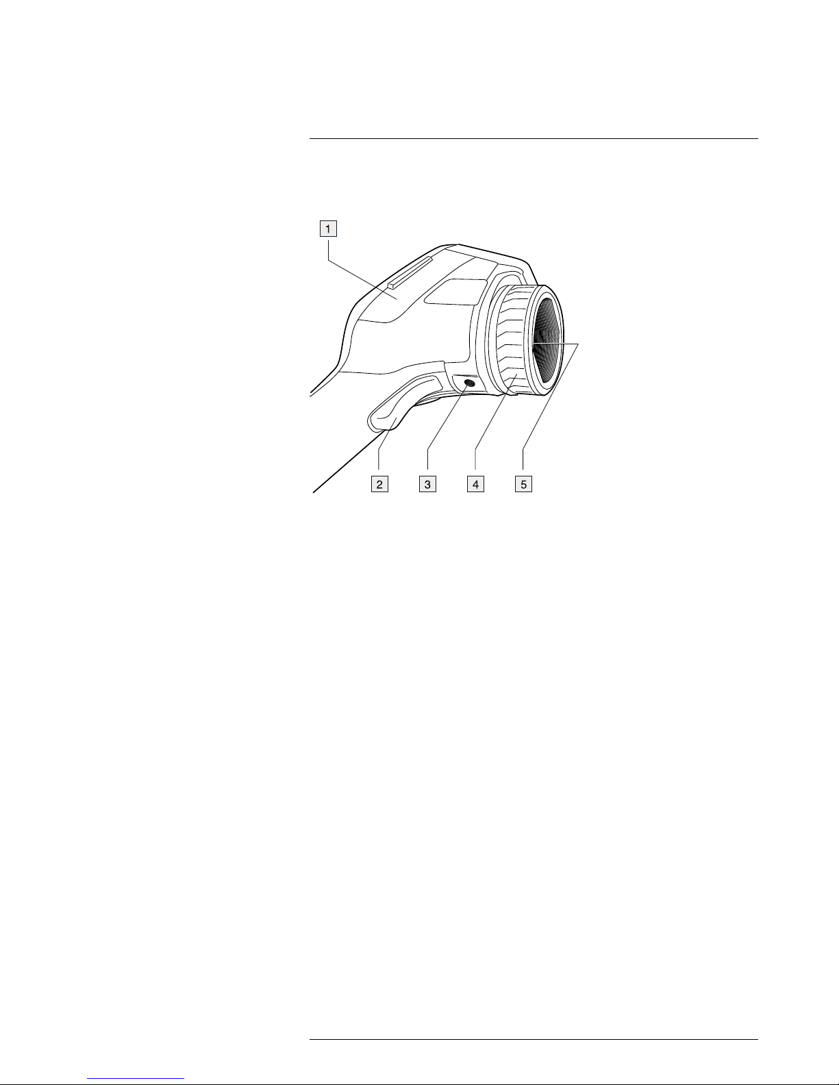
7.1 View from the right
7.1.1 Figure
7.1.2 Explanation
1. Cover for the right-hand compartment:
• USB-A connector.
• USB mini-B connector.
• Power connector.
2. Save button.
3. Tripod mount. Requires an adapter (extra accessory).
4. Focus ring.
5. Infrared lens.
#T559845; r. AJ/37554/37554; en-US
13
Page 24
Camera parts
7
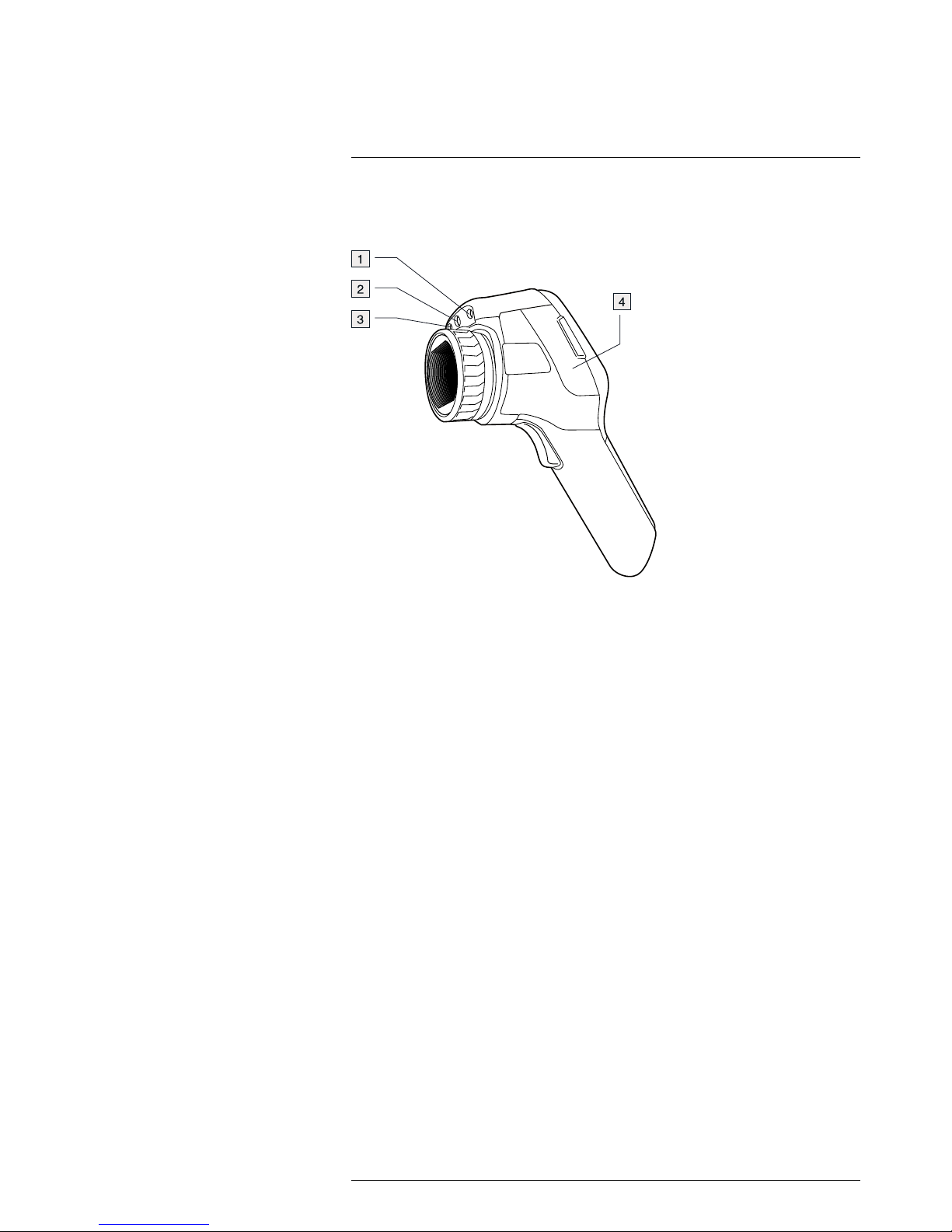
7.2 View from the left
7.2.1 Figure
7.2.2 Explanation
1. Laser pointer.
2. Lamp for the digital camera.
3. Digital camera.
4. Cover for the left-hand compartment:
• Video out connector (composite video).
• Memory card slot.
#T559845; r. AJ/37554/37554; en-US
14
Page 25
Camera parts
7
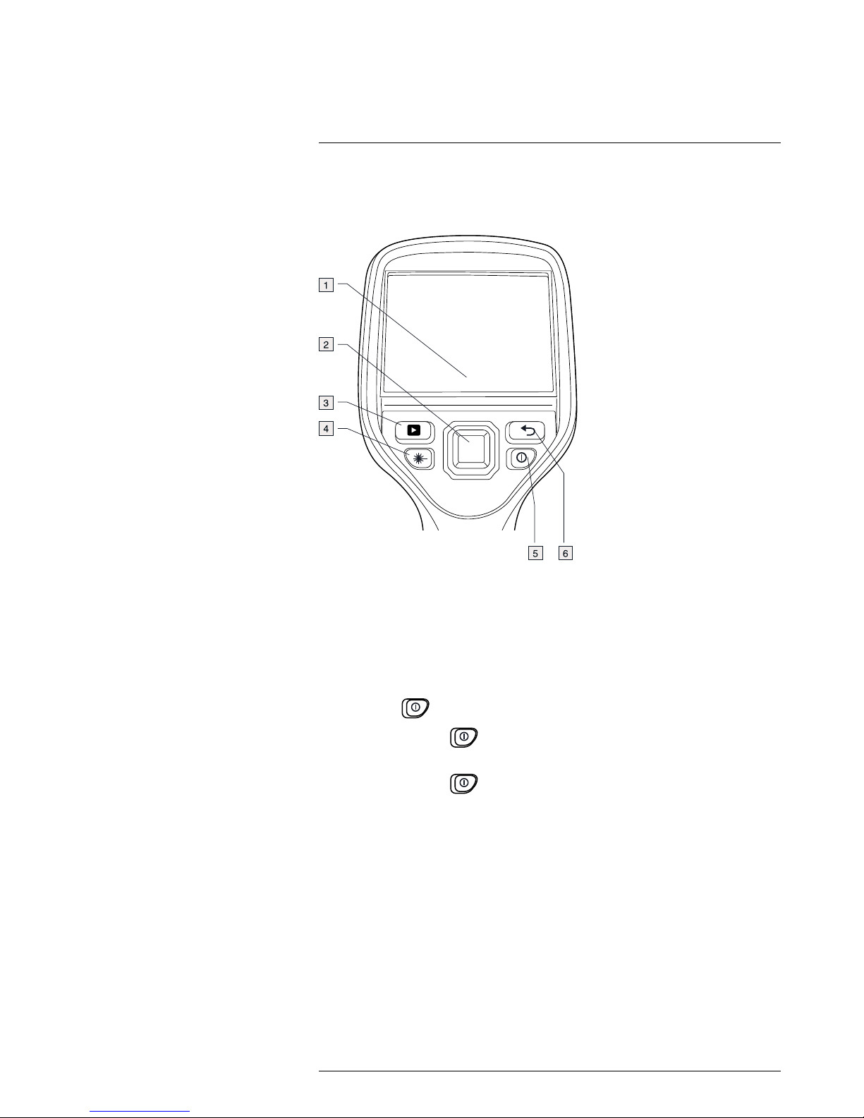
7.3 LCD and keypad
7.3.1 Figure
7.3.2 Explanation
1. Touch-screen LCD.
2. Navigation pad with center push.
3. Image archive button.
4. Button to operate the laser pointer.
5. On/off button.
Function:
• Push the
button to turn on the camera.
• Push and hold the
button for less than 5 seconds to put the camera in stand-
by mode. The camera then automatically turns off after 6 hours.
• Push and hold the
button for more than 10 seconds to turn off the camera.
6. Back button.
#T559845; r. AJ/37554/37554; en-US
15
Page 26
Camera parts
7
7.4 View from the bottom
7.4.1 Figure
7.4.2 Explanation
1. Latch to open the cover for the battery compartment. Push to open.
#T559845; r. AJ/37554/37554; en-US
16
Page 27
Camera parts
7
7.5 Battery condition LED indicator
7.5.1 Figure
7.5.2 Explanation
Type of signal Explanation
The green LED flashes two times per second. The battery is being charged.
The green LED glows continuously. The battery is fully charged.
#T559845; r. AJ/37554/37554; en-US
17
Page 28
Camera parts
7
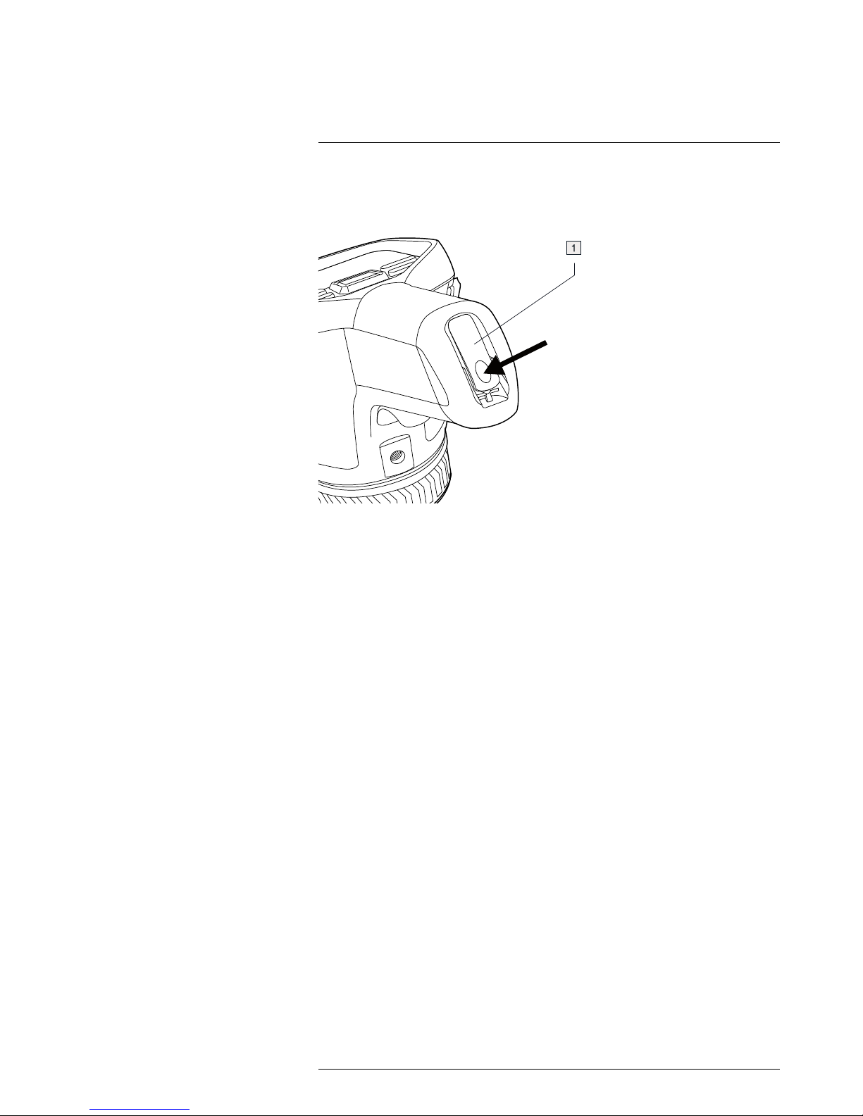
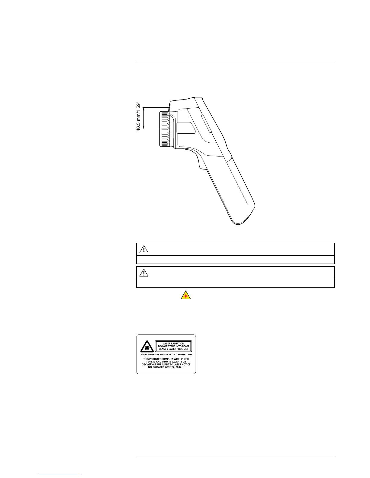
7.6 Laser pointer
7.6.1 Figure
Figure 7.1 This figure shows the difference in position between the laser pointer and the optical center of
the infrared lens.
WARNING
Do not look directly into the laser beam. The laser beam can cause eye irritation.
CAUTION
Protect the laser pointer with the protective cap when you are not using the laser pointer.
Note The symbol
is displayed on the screen when the laser pointer is on.
Note The laser pointer may not be enabled in all markets.
7.6.2 Laser warning label
A laser warning label with the following information is attached to the camera:
7.6.3 Laser rules and regulations
Wavelength: 635 nm. Maximum output power: 1 mW.
This product complies with 21 CFR 1040.10 and 1040.11 except for deviations pursuant
to Laser Notice No. 50, dated June 24, 2007.
#T559845; r. AJ/37554/37554; en-US
18
Page 29

Screen elements
8
8.1 Figure
8.2 Explanation
1. Measurement tools (e.g., spotmeter).
2. Measurement result table.
3. Status icons and notifications.
4. Temperature scale.
5. Lamp toolbar button.
6. Temperature scale toolbar button.
7. Color toolbar button.
8. Measurement toolbar button.
9. Image modes toolbar button.
10. Recording mode toolbar button.
11. Settings toolbar button.
Note To display the menu system, tap the screen or push the navigation pad.
#T559845; r. AJ/37554/37554; en-US
19
Page 30
Navigating the menu system
9
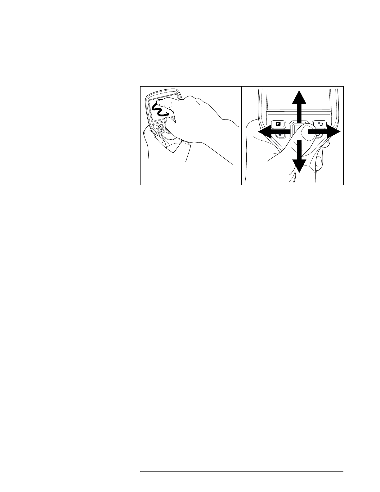
9.1 Figure
9.2 Explanation
The figure above shows the two ways to navigate the menu system in the camera:
• Using the touch screen LCD to navigate the menu system (left).
• Using the navigation pad to navigate the menu system (right).
#T559845; r. AJ/37554/37554; en-US
20
Page 31

Connecting external devices and
storage media
10
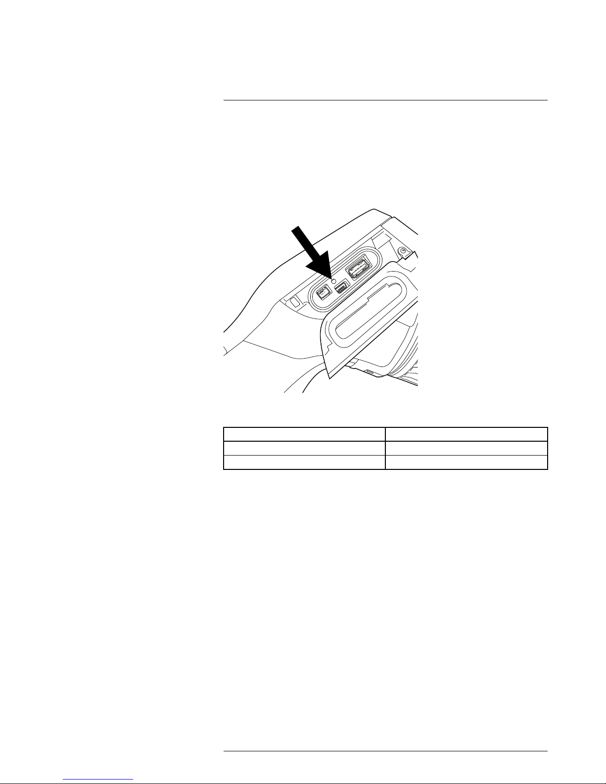
10.1 Figure
10.2 Explanation
1. Indicator showing that the memory card is busy.
Note Do not eject the SD memory card when this LED is flashing.
2. Memory card (SD card)
3. Video cable.
#T559845; r. AJ/37554/37554; en-US
21
Page 32

Connecting external devices and storage media
10
10.3 Figure
10.4 Explanation
1. Power cable.
2. USB mini-B cable (to connect the camera to a PC).
3. USB-A cable (to connect the camera to an external device, e.g., a USB memory
stick).
#T559845; r. AJ/37554/37554; en-US
22
Page 33

Pairing Bluetooth devices
11
11.1 General
You can use Bluetooth-enabled headsets and FLIR meters together with the camera. Before you can use the device with the camera, you need to pair the camera and the device.
11.2 Procedure
Follow this procedure:
1. Enable Bluetooth on the device. See the user documentation for that device for information on how to do this.
2. On the camera, push the navigation pad to display the menu system.
3. Use the navigation pad to go to Settings.
4. Push the navigation pad.
5. Select Device settings and push the navigation pad.
6. Select Bluetooth including METERLiNK and push the navigation pad.
7. Enable Bluetooth by pushing the navigation pad.
8. Select Scan for Bluetooth devices and push the navigation pad right.
9. When the device is displayed in the list of devices, select it and push the navigation
pad to pair the camera and the device.
Note
• Only METERLiNK devices and Bluetooth-enabled headsets will appear in the list of
available devices.
• You can add several devices.
• You can remove a device by selecting the device and then selecting Unpair device.
• After adding a METERLiNK device, such as the FLIR MR77 or FLIR CM78, the result
from the meter will be visible in the measurement result table.
• After adding a Bluetooth-enabled headset, it is ready to be used for adding voice
annotations.
#T559845; r. AJ/37554/37554; en-US
23
Page 34

Configuring Wi-Fi
12
12.1 General
You can connect the camera in two different ways:
• Most common use: Setting up a peer-to-peer connection (also called an ad hoc or
P2P connection). This method is primarily used with other devices, e.g., an iPhone or
iPad.
• Less common use: Connecting the camera to a wireless local area network (WLAN).
12.2 Setting up a peer-to-peer connection (most common use)
Follow this procedure:
1. On the camera, push the navigation pad to display the menu system.
2. Use the navigation pad to go to Settings.
3. Push the navigation pad.
4. Select Device settings and push the navigation pad.
5. Select Wi-Fi and push the navigation pad.
6. Select Share and push the navigation pad.
7. (Optional step.) To display and change the parameters, select Settings and push the
navigation pad.
• If the transfer rate is low, this can be due to a crowded frequency band. Try chang-
ing the channel to increase the transfer rate. To change the channel (the channel
that the camera is broadcasting on), select Channel and push the navigation pad.
• To activate WEP (encryption algorithm), select WEP and push the navigation pad.
This will check the WEP check box.
• To change the WEP password, select Password and push the navigation pad.
Note These parameters are set for your camera’s network. They will be used by the
external device to connect that device to the network.
12.3 Connecting the camera to a wireless local area network (less common use)
Follow this procedure:
1. On the camera, push the navigation pad to display the menu system.
2. Use the navigation pad to go to Settings .
3. Push the navigation pad.
4. Select Device settings and push the navigation pad.
5. Select Wi-Fi and push the navigation pad.
6. Select Connect to network and push the navigation pad.
7. Select Networks and push the navigation pad right.
8. Select a network by pushing the navigation pad. You typically need to enter a password to access the network.
Note Some networks do not broadcast their existence. To connect to such a network,
select Settings from the Networks list and push the navigation pad. Then select Add net-
work... and set all parameters manually for that network.
#T559845; r. AJ/37554/37554; en-US
24
Page 35

Handling the camera
13
13.1 Charging the battery
Note You must charge the battery for 4 hours before you start using the camera for the
first time.
13.1.1 Using the power supply to charge the battery
13.1.1.1 Procedure
Follow this procedure:
1. Connect the power supply cable plug to the power connector on the camera.
2. Connect the power supply mains-electricity plug to a mains socket.
3. Disconnect the power supply cable plug when the battery condition LED indicator is
a continuous green.
13.1.2 Using the stand-alone battery charger to charge the battery
13.1.2.1 Explanation
Type of signal Explanation
The blue LED flashes. The battery is being charged.
The blue LED glows continuously. The battery is fully charged.
13.1.2.2 Procedure
Follow this procedure:
1. Put the battery in the battery charger.
2. Connect the power supply cable plug to the connector on the battery charger.
3. Connect the power supply mains-electricity plug to a mains socket.
4. Disconnect the power supply cable plug when the blue LED on the battery charger is
continuous.
13.2 Turning on and turning off the camera
• Push the
button to turn on the camera.
• Push and hold the
button for less than 5 seconds to put the camera in standby
mode. The camera then automatically turns off after 6 hours.
• Push and hold the
button for more than 10 seconds to turn off the camera.
#T559845; r. AJ/37554/37554; en-US
25
Page 36

Handling the camera13
13.3 Adjusting the infrared camera focus
13.3.1 Figure
13.3.2 Procedure
Follow this procedure:
1. Do one of the following:
• For far focus, rotate the focus ring clockwise (with the touch-screen LCD facing to-
ward you).
• For near focus, rotate the focus ring counter-clockwise (with the touch-screen
LCD facing toward you).
Note Do not touch the lens surface when you adjust the infrared camera focus manually. If this happens, clean the lens according to the instructions in 26.2 Infrared lens,
page 132.
Note It is very important to adjust the focus correctly. Incorrect focus adjustment affects
how the image modes Thermal MSX, Thermal, and Picture-in-picture work. It also affects
the temperature measurement.
#T559845; r. AJ/37554/37554; en-US
26
Page 37

Handling the camera13
13.4 Operating the laser pointer
13.4.1 Figure
13.4.2 Procedure
Follow this procedure:
1. To turn on the laser pointer, push and hold the laser button.
2. To turn off the laser pointer, release the laser button.
Note
• A warning indicator is displayed on the screen when the laser pointer is turned on.
• The position of the laser dot is indicated on the infrared image (depending on the
camera model).
13.5 Removing the battery
Follow this procedure:
1. Push the latch on the battery compartment.
2. Open the battery cover.
#T559845; r. AJ/37554/37554; en-US
27
Page 38

Handling the camera13
3. Pull the transparent tape to lift out the battery.
13.6 Mounting an accessory lens
Follow this procedure:
1. Note the two indents on the front of the lens and the corresponding tabs on the lens
cap.
2. Use the lens cap from the accessory lens as a tool to remove the plastic front of the
lens. Rotate the plastic front 30° degrees counter-clockwise.
3. Note the index marks on the lens bayonet mount and on the replacement lens.
4. Carefully push the lens into position.
#T559845; r. AJ/37554/37554; en-US
28
Page 39

Handling the camera13
5. Rotate the lens 30° clockwise.
6. Turn on the camera.
7. Specify the lens under Settings > Add-on lens.
13.7 Calibrating the touchscreen
13.7.1 Figure
13.7.2 Procedure
Follow this procedure:
1. Push the navigation pad to display the menu system.
2. Use the navigation pad to go to Settings.
3. Push the navigation pad.
4. Select Device settings and push the navigation pad.
5. Select Setup camera and push the navigation pad.
6. Select Calibrate touchscreen and push the navigation pad.
7. Follow the on-screen instructions.
13.8 Using the camera lamp
13.8.1 General
The camera lamp can be used as a flash for the digital camera. When the flash function
is activated, the camera lamp will flash when an image is saved by pushing the Save
button.
The camera lamp can also be used as a flashlight.
#T559845; r. AJ/37554/37554; en-US
29
Page 40

Handling the camera13
13.8.2 Procedure
Follow this procedure:
1. Push the navigation pad to display the menu system.
2. Use the navigation pad to go to Lamp.
3. Push the navigation pad.
4. Do one of the following:
• To enable the flash function, select Flash and push the navigation pad.
• To turn on the camera lamp, select On and push the navigation pad.
• To disable the flash function and to turn off the camera lamp, select Off and push
the navigation pad.
#T559845; r. AJ/37554/37554; en-US
30
Page 41

Working with images
14
14.1 Saving an image
14.1.1 General
You can save images to a memory card.
The camera saves an image file including all thermal and visual information. This means
that you can open an image file at a later time and, for example, select another image
mode, apply color alarms, and add measurement tools.
14.1.2 Image capacity
This table gives information on the approximate number of infrared (IR) and digital camera (DC) images that can be saved on memory cards:
Card size
IR only
IR + DC
IR + DC + 30 seconds
voice annotation
1 GB
5500 850 600
2 GB
11 000 1700 1200
14.1.3 Naming convention
The naming convention for images is FLIRxxxx.jpg, where xxxx is a unique counter.
14.1.4 Procedure
Follow this procedure:
1. To save an image, push the Save button.
Note
• Depending on the settings in the Settings > Save options dialog box, the following
may happen:
◦ A preview image is displayed before the image is saved.
◦ An annotation tool or the annotation menu is displayed when the image has been
saved.
14.2 Previewing an image
14.2.1 General
You can preview an image before you save it. This enables you to see if the image contains the information you want before you save it. You can also adjust and edit the image.
Note The camera must be configured to display a preview image before saving. Select
Settings> Save options > Preview image before saving = On.
14.2.2 Procedure
Follow this procedure:
1. To preview an image, push the Save button. This displays the preview.
2. Manual image adjust mode is now active, and the status icon
is displayed. For
image adjustment instructions, see 14.5 Adjusting an infrared image, page 32.
3. To edit the image, push the navigation pad. This displays a toolbar. For editing instructions, see 14.4 Editing a saved image, page 32.
4. Do one of the following:
• To save the image, push the Save button.
• To exit preview mode without saving, push the Back button
. A dialog box
appears, asking you to cancel or save any changes.
#T559845; r. AJ/37554/37554; en-US
31
Page 42

Working with images14
14.3 Opening a saved image
14.3.1 General
When you save an image, the image is stored on a memory card. To display the image
again, open it from the memory card.
14.3.2 Procedure
Follow this procedure:
1. Push
to open the image archive.
2. Push the navigation pad up/down or left/right to select the image you want to view.
3. Push the navigation pad to open the image.
4. Do one or more of the following:
• To switch between an infrared image and a visual image, push the navigation pad
up/down.
• To view the previous/next image, push the navigation pad left/right.
• To edit the image, add annotations, display information, or delete the image, push
the navigation pad. This displays a toolbar.
• To return to the image archive overview, push the Back button
.
5. Push the Back button
to leave the image archive.
14.4 Editing a saved image
14.4.1 General
You can edit a saved image. You can also edit an image in preview mode.
14.4.2 Procedure
Follow this procedure:
1. Open the image in the image archive.
2. Push the navigation pad and select Edit from the toolbar.
3. Manual image adjust mode is now active, and the status icon
is displayed. For
image adjustment instructions, see 14.5 Adjusting an infrared image, page 32.
4. Push the navigation pad. This displays a toolbar.
• Select Cancel to exit edit mode.
• Select Measurement parameters to change the global parameters.
• Select Image mode to change the image mode.
• Select Measurement to add a measurement tool.
• Select Color to change the color palette or set a color alarm.
• Select Temperature scale to adjust the image.
• Select Save to save and exit edit mode.
14.5 Adjusting an infrared image
14.5.1 General
An infrared image can be adjusted automatically or manually. When manual image adjust
mode is active, the status icon
is displayed.
• In live mode, select Temperature scale from the menu system to switch between auto-
matic and manual image adjust modes.
• In live mode, you can also select manual image adjust mode by touching the minimum
or maximum temperature scale level on the screen.
• In preview/edit mode, manual image adjust mode is active.
#T559845; r. AJ/37554/37554; en-US
32
Page 43

Working with images14
There are two different manual image adjust modes. Select the type of mode under Settings > Device settings > Set up camera > Level span mode.
• Level / span: This mode allows you to manually adjust the level and span of the tem-
perature scale.
• Level / max / min: In this mode, you can manually adjust the temperature scale mini-
mum and maximum limits, simultaneously or individually.
14.5.2 Example 1
Here are two infrared images of a building. In the left image, which is auto-adjusted, the
large temperature span between the clear sky and the heated building makes a correct
analysis difficult. You can analyze the building in more detail if you change the temperature scale to values close to the temperature of the building.
Automatic Manual
14.5.3 Example 2
Here are two infrared images of an isolator in a power line. To make it easier to analyze
the temperature variations in the isolator, the temperature in the right image has been
changed to values close to the temperature of the isolator.
Automatic Manual
14.5.4 Manual adjustment in Level / span mode
Note This procedure assumes that you have configured the camera to do manual image adjustments in Level / span mode. Select Settings > Device settings > Set up cam-
era > Level span mode = Level / span.
Follow this procedure:
1. Push the navigation pad to display the menu system.
2. Use the navigation pad to go to Temperature scale.
3. Push the navigation pad.
4. Select Manual and push the navigation pad.
5. Push the navigation pad up/down to increase/decrease the level.
6. Push the navigation pad right/left to increase/decrease the span.
#T559845; r. AJ/37554/37554; en-US
33
Page 44

Working with images14
14.5.5 Manual adjustment in Level / max / min mode
Note This procedure assumes that you have configured the camera to do manual image adjustments in Level / max / min mode. Select Settings > Device settings > Set up
camera > Level span mode = Level / max / min.
Follow this procedure:
1. Push the navigation pad to display the menu system.
2. Use the navigation pad to go to Temperature scale.
3. Push the navigation pad.
4. Select Manual and push the navigation pad.
5. To simultaneously change the temperature scale minimum and maximum limits, push
the navigation pad up/down.
6. To change the minimum limit or the maximum limit, do the following:
• Push the navigation pad left/right to select (highlight) the maximum or minimum
temperature.
• Push the navigation pad up/down to change the value of the highlighted
temperature.
14.6 Performing a non-uniformity correction (NUC)
14.6.1 What is a non-uniformity correction?
A non-uniformity correction is an image correction carried out by the camera software to
compensate for different sensitivities of detector elements and other optical and geometrical disturbances
1
.
14.6.2 When to perform a non-uniformity correction?
The non-uniformity correction process should be carried out whenever the output image
becomes spatially noisy. The output can become spatially noisy when the ambient temperature changes (such as from day to night operation, and vice versa).
14.6.3 Procedure
To perform a non-uniformity correction, push and hold the Image archive button
for
more than 2 seconds.
14.7 Changing the temperature range
14.7.1 General
You must change the temperature range according to the expected temperature of the
object you are inspecting.
14.7.2 Procedure
Follow this procedure:
1. Push the navigation pad to display the menu system.
2. Use the navigation pad to go to Settings.
3. Push the navigation pad.
4. Select Device settings and push the navigation pad.
5. Select Set up camera and push the navigation pad.
6. Select Camera temperature range and push the navigation pad.
7. Select the appropriate temperature range and push the navigation pad.
#T559845; r. AJ/37554/37554; en-US
34
1. Definition from the impending international adoption of DIN 54190-3 (Non-destructive testing – Thermographic
testing – Part 3: Terms and definitions).
Page 45

Working with images14
14.8 Changing the color palette
14.8.1 General
You can change the color palette that the camera uses to display different temperatures.
A different palette can make it easier to analyze an image.
14.8.2 Procedure
Follow this procedure:
1. Push the navigation pad to display the menu system.
2. Use the navigation pad to go to Color.
3. Push the navigation pad.
4. Use the navigation pad to select a different color palette.
5. Push the navigation pad to confirm the choice.
Note Some color options hold specific meanings, such as acting as isotherms or
alarms. For more information, see section 17 Working with alarms, page 42.
14.9 Zooming in on an image
14.9.1 General
You can zoom in on an image using the camera’s digital zoom function. You can do this
on both live images and saved images.
14.9.2 Procedure
Follow this procedure:
1. To zoom in on an image, tap and hold your finger down on the screen. This displays
a zoom toolbar.
2. On the zoom toolbar, tap a zoom factor.
Once the zoom factor has been selected, it is displayed in the notification area at the
top of the screen.
14.10 Deleting an image
14.10.1 Procedure
Follow this procedure:
1. Push
to open the image archive.
2. Push the navigation pad up/down or left/right to select the image you want to view.
3. Push the navigation pad to open the image.
4. Push the navigation pad to display a toolbar
5. On the toolbar, select Delete and push the navigation pad.
6. Push
to leave the image archive.
#T559845; r. AJ/37554/37554; en-US
35
Page 46

Working with images14
14.11 Deleting all images
14.11.1 Procedure
Follow this procedure:
1. Push the navigation pad to display the menu system.
2. Use the navigation pad to go to Settings.
3. Push the navigation pad.
4. Select Device settings and push the navigation pad.
5. Select Reset options and push the navigation pad.
6. Select Delete all saved images and push the navigation pad.
#T559845; r. AJ/37554/37554; en-US
36
Page 47

Working with image modes
15
15.1 General
You can choose between different image modes when capturing an image.
15.2 Types of image modes
These are the image modes you can choose from:
Thermal MSX (Multi Spectral Dynamic Imaging):
Using this mode, the camera captures infrared images where the edges of the objects are enhanced. Note that the label for each fuse is clearly
legible.
Thermal: Using this mode, the camera captures
an ordinary infrared image.
Picture-in-picture: Using this mode, the camera
captures an infrared image frame that is displayed
on top of a digital photo.
Digital camera: Using this mode, the camera captures an ordinary digital photo.
#T559845; r. AJ/37554/37554; en-US
37
Page 48

Working with image modes15
15.3 Procedure
Follow this procedure:
1. Push the navigation pad to display the menu system.
2. Use the navigation pad to go to Image modes.
3. Push the navigation pad.
4. Select one of the following image modes:
• Thermal MSX.
• Thermal.
• Picture-in-picture.
• Digital camera.
Note The data for all image modes are saved when saving an image. Therefore, if you
open an image in, e.g., FLIR Tools or in the image archive you can still change the image
mode.
#T559845; r. AJ/37554/37554; en-US
38
Page 49

Working with measurement tools
16
16.1 Laying out measurement tools in live mode
16.1.1 General
To measure a temperature, you use one or more measurement tools, e.g., a spotmeter
or a box. The camera is equipped with a number of preset measurement tools.
16.1.2 Procedure
Follow this procedure:
1. Push the navigation pad to display the menu system.
2. Use the navigation pad to go to Measurement.
3. Push the navigation pad. This displays a measurement toolbar.
4. On the toolbar, select one of the following and push the navigation pad:
• No measurements: Clears all measurement tools from the screen.
• Center spot: A centered spotmeter on the screen.
• Hot spot: A moving spotmeter indicating the hottest temperature within a box.
• Cold spot: A moving spotmeter indicating the coldest temperature within a box.
• 3 spots: Three spots vertically centered.
• Hot spot - Spot: The temperature difference between the hot spotmeter and the
spotmeter.
• Hot spot - Temp: The temperature difference between the hot spotmeter and a set
temperature.
16.2 Laying out measurement tools in edit mode
16.2.1 General
You lay out measurement tools in recall mode by opening an image in the image archive.
16.2.2 Procedure
Follow this procedure:
1. Push
to open the image archive.
2. Push the navigation pad up/down or left/right to select the image you want to view.
3. Push the navigation pad to open the image.
4. Push the navigation pad to display a toolbar.
5. On the toolbar, select Edit and push the navigation pad. This opens the image in edit
mode.
6. Push the navigation pad to display a toolbar.
7. On the toolbar, select Measurement. This displays a toolbar.
8. On the toolbar, select one of the following and push the navigation pad:
• Add spot: Adds a spotmeter.
• Add box: Adds a box.
• Add delta: Adds a difference calculation for two measurement tools.
9. Push the Back button to leave edit mode. A dialog box appears, asking you to cancel
or save any changes.
#T559845; r. AJ/37554/37554; en-US
39
Page 50

Working with measurement tools16
16.3 Moving and resizing measurement tools
16.3.1 General
You can move and resize measurement tools in various ways.
16.3.2 Procedure
Note
• This procedure assumes that you have previously laid out a measurement tool on the
screen.
• You can also move and resize the measurement tool by touching the screen.
Follow this procedure:
1. To select the measurement tool, touch the tool on the screen. The tool is now displayed with one or more handles.
Spot measurement tool:
Area measurement tool:
2. Push the navigation pad. This displays a toolbar.
• Select Resize to change the size of the tool.
• Select Move to move the tool.
• Select Center to move the tool to the center of the screen.
3. Push the navigation pad up/down and left/right to resize or move the tool.
4. When completed, push the navigation pad and select Done.
16.4 Displaying maximum, minimum, and average values
16.4.1 General
For the box tools, including the hot spot and the cold spot tools, you can set the camera
to display the maximum, minimum, and average values. You can also display markers indicating the maximum and minimum values in the box.
16.4.2 Procedure
Follow this procedure:
1. To select the measurement tool, touch the tool on the screen. The tool is now displayed with one or more handles.
2. Push the navigation pad. This displays a toolbar.
3. Use the navigation pad to go to Max/Min/Avg/Alarm.
4. Push the navigation pad. This displays a toolbar.
• Select Max and push the navigation pad to display the maximum value.
• Select Min and push the navigation pad to display the minimum value.
• Select Avg and push the navigation pad to display the average value.
• Select Max & min markers and push the navigation pad to display markers for the
maximum and minimum values.
5. When completed, push the navigation pad down to close the upper toolbar.
6. Select Done and push the navigation pad.
#T559845; r. AJ/37554/37554; en-US
40
Page 51

Working with measurement tools16
16.5 Setting local measurement parameters for a measurement tool
16.5.1 General
When you set measurement parameters under Settings, all the parameters for the whole
image are changed.
However, in some situations you may want to change a measurement parameter for one
measurement tool only. The reason for this could be that the measurement tool is in front
of a significantly more reflective surface than other surfaces in the image, or over an object that is further away than the rest of the objects in the image, and so on.
For more information about object parameters, see section 22.3.1 Measurement param-
eters, page 49.
16.5.2 Procedure
Note This procedure assumes that you have laid out a measurement tool on the
screen.
Follow this procedure:
1. To select the measurement tool, touch the tool on the screen. The tool is now displayed with one or more handles.
2. Push the navigation pad. This displays a toolbar.
3. Use the navigation pad to go to Use local parameters
.
4. Push the navigation pad.
(icon with grey indicator) is displayed.
5. Push the navigation pad to activate the use of local parameters.
(icon with
blue indicator) is displayed together with a toolbar.
6. Select an object parameter:
• Emissivity.
• Reflected temperature.
• Object distance.
7. Push the navigation pad to display a dialog box.
8. Push the navigation pad up/down to change the parameter.
9. When completed, push the navigation pad.
#T559845; r. AJ/37554/37554; en-US
41
Page 52

Working with alarms
17
17.1 Working with color alarms
17.1.1 General
A color alarm applies a contrasting color to all pixels with a temperature above, below, or
between one or more set temperature levels.
Using a color alarm is a good method to easily discover anomalies in an infrared image.
17.1.2 Procedure
Follow this procedure:
1. Push the navigation pad to display the menu system.
2. Use the navigation pad to go to Color.
3. Push the navigation pad. This displays a color toolbar.
4. On the toolbar, select one of the following and push the navigation pad:
• Above alarm: A color alarm that colorizes all parts of the image that are above a
set temperature level. Use the navigation pad to change the temperature.
• Below alarm: A color alarm that colorizes all parts of the image that are below a
set temperature level. Use the navigation pad to change the temperature.
• Interval alarm: An interval color alarm that colorizes all parts of the image that fall
between two set temperature levels. Use the navigation pad to change the temperature levels.
17.2 Working with insulation alarms
17.2.1 General
The Insulation alarm can detect areas where there may be an insulation deficiency in a
building. It will trigger when the insulation level (termed the thermal index in the camera
menu) falls below or above a preset value of the energy leakage through a wall (depending on the climate conditions).
Different building codes recommend different values for the insulation level, but typical
values are 60–80% for new buildings. Refer to your national building code for
recommendations.
17.2.2 Procedure
Follow this procedure:
1. Push the navigation pad to display the menu system.
2. Use the navigation pad to go to Color.
3. Push the navigation pad.
#T559845; r. AJ/37554/37554; en-US
42
Page 53

Working with alarms17
4. Use the navigation pad to select Insulation alarm. This displays a dialog box.
5. Use the navigation pad to set the following parameters:
• Indoor temperature: The current indoor temperature.
• Outdoor temperature: The current outdoor temperature.
• Thermal index: The insulation level, an integer between 0 and 100.
17.3 Working with condensation alarms
17.3.1 General
The Condensation alarm can detect areas with potential moisture problems. You can set
the relative humidity above which the camera will colorize the image.
17.3.2 Procedure
Follow this procedure:
1. Push the navigation pad to display the menu system.
2. Use the navigation pad to go to Color.
3. Push the navigation pad.
4. Use the navigation pad to select Condensation alarm. This displays a dialog box.
5. Use the navigation pad to set the following parameters:
• Atmospheric temperature: The current atmospheric temperature.
• Relative humidity: The current relative humidity.
• Relative humidity limit: The relative humidity level at which you want the alarm to
be triggered—100% indicates that the water vapor condenses as liquid water (=
dewpoint).
#T559845; r. AJ/37554/37554; en-US
43
Page 54

Fetching data from external FLIR
meters
18
18.1 General
You can fetch data from an external FLIR meter and add this data to the infrared image.
When the camera is connected to a FLIR meter via Bluetooth, the measurement value
from the meter is displayed in the result table of the camera. The FLIR meter value is also
added to the information saved in the image file.
18.2 Supported meters
• FLIR CM78
• FLIR CM83
• FLIR DM93
• FLIR MR77
18.3 Technical support for external meters
Website http://www.flir.com/test
Technical support TMSupport@flir.com
Repairs Repair@flir.com
Phone number +1 855-499-3662 (toll-free)
18.4 Procedure
Note This procedure assumes that you have paired the Bluetooth devices. For more in-
formation, see section 11 Pairing Bluetooth devices, page 23.
Follow this procedure:
1. Turn on the camera.
2. Turn on the FLIR meter.
3. On the meter, enable Bluetooth mode. Refer to the user documentation for the meter
for information on how to do this.
4. On the meter, choose the quantity that you want to use (voltage, current, resistance,
etc.). Refer to the user documentation for the meter for information on how to do this.
Results from the meter will now automatically be displayed in the result table in the
top left corner of the infrared camera screen.
18.5 Typical moisture measurement and documentation procedure
18.5.1 General
The following procedure can form the basis for other procedures using FLIR meters and
infrared cameras.
18.5.2 Procedure
Follow this procedure:
1. Use the infrared camera to identify any potential damp areas behind walls and
ceilings.
2. Use the moisture meter to measure the moisture levels at various suspect locations
that may have been found.
3. When an area of particular interest is located, store the moisture reading in the moisture meter’s memory and identify the measurement area with a handprint or other
thermal identifying marker.
4. Recall the reading from the meter memory. The moisture meter will now continuously
transmit this reading to the infrared camera.
5. Use the camera to take a thermal image of the area with the identifying marker. The
stored data from the moisture meter will also be saved on the image.
#T559845; r. AJ/37554/37554; en-US
44
Page 55

Annotating images
19
19.1 General
This section describes how to save additional information together with an infrared image
by using annotations.
Using annotations makes reporting and post-processing more efficient by providing essential information about the image or the situation when it was taken.
• You can set the camera to display annotation tools when an image is saved. For more
information, see section 22.3.2.2 Add annotation after saving, page 50.
• You can also add annotations to a saved image in the image archive.
Note This section describes the procedures for adding annotations to a saved image
in the image archive. Adding annotations when saving an image works in a similar way.
19.2 Adding a note
19.2.1 General
A text note is grouped with the image file. Using this feature, you can annotate images by
entering free-form text.
19.2.2 Procedure
Follow this procedure:
1. Push
to open the image archive.
2. Push the navigation pad up/down or left/right to select the image to which you want to
add a text annotation.
3. Push the navigation pad to open the image.
4. Push the navigation pad to display a toolbar.
5. On the toolbar, select Add note and push the navigation pad. This displays a soft keyboard where you can enter the text you want to save.
Note To select special characters, press and hold down the corresponding key on
the soft keyboard.
6. When completed, touch Done on the soft keyboard. After the note is saved, a note
icon is displayed in the bottom right corner of the image.
19.3 Adding a table
19.3.1 General
You can save a table with textual information to the image file. This feature is a very efficient way of recording information when you are inspecting a large number of similar objects. The idea behind using a table with textual information is to avoid filling out forms or
inspection protocols manually.
The camera has a number of default table templates. You can also import your own table
templates from FLIR Tools. The templates are stored on the memory card.
#T559845; r. AJ/37554/37554; en-US
45
Page 56

Annotating images19
19.3.2 Procedure
Follow this procedure:
1. Push
to open the image archive.
2. Push the navigation pad up/down or left/right to select the image to which you want to
add a table annotation.
3. Push the navigation pad to open the image.
4. Push the navigation pad to display a toolbar.
5. On the toolbar, select Add table and push the navigation pad.
6. Select Add table contents and push the navigation pad. This displays the default
template.
Note You can select another template by first selecting Select default template.
7. For each row in the table, do the following:
• Push the navigation pad. This displays the predefined values.
• Push the navigation pad up/down to select a predefined value. Push the naviga-
tion pad to confirm.
• Instead of selecting a predefined value, you can select the keyboard
and enter
other text.
8. When completed, select Save & Exit at the bottom of the table. Push the navigation
pad to confirm.
19.4 Adding a voice annotation
19.4.1 General
A voice annotation is an audio recording that is stored in an infrared image file.
The voice annotation is recorded using a Bluetooth headset. The recording can be
played back in the camera, and in image analysis and reporting software from FLIR
Systems.
19.4.2 Procedure
Note This procedure assumes that you have paired the camera with a Bluetooth headset. For information on how to do this, see section 11 Pairing Bluetooth devices, page 23.
Follow this procedure:
1. Push
to open the image archive.
2. Push the navigation pad up/down or left/right to select the image to which you want to
add a voice annotation.
3. Push the navigation pad to open the image.
4. Push the navigation pad to display a toolbar.
5. On the toolbar, select Add voice annotation and push the navigation pad. This displays a recording toolbar.
6. Select Record and push the navigation pad to start a recording.
7. Select Stop and push the navigation pad to stop the recording.
8. Select Play and push the navigation pad to listen to the recording.
9. Select Delete and push the navigation pad to delete the recording.
10. When completed, select Done and push the navigation pad.
#T559845; r. AJ/37554/37554; en-US
46
Page 57

Recording video clips
20
20.1 General
You can record non-radiometric video clips in the following image modes:
• Thermal MSX.
• Thermal.
• Picture-in-picture.
• Digital camera.
The video clips can be played back in Microsoft Windows Media Player, but it will not be
possible to retrieve any temperature values from them.
20.2 Procedure: Recording a video clip
Follow this procedure:
1. Push the navigation pad to display the menu system.
2. Use the navigation pad to go to Recording mode.
3. Push the navigation pad.
4. Select Video and push the navigation pad.
5. Push the Save button to start the recording. A red icon at the top of the image blinks
during the recording.
6. Push the Save button again to stop the recording.
20.3 Procedure: Playing a video clip
Follow this procedure:
1. Push
to open the image archive.
2. Push the navigation pad up/down or left/right to select the video clip that you want to
play.
3. Push the navigation pad to open the video clip.
4. Push the navigation pad to display a toolbar.
5. On the toolbar, select Play and push the navigation pad.
#T559845; r. AJ/37554/37554; en-US
47
Page 58

Screening alarm
21
21.1 General
The screening alarm can be used, for example, at airports to detect passengers with elevated body temperatures, which may indicate the presence of a fever.
Activating the screening alarm will turn on a measurement box and screening data in the
result table.
The sampled average temperature.
The alarm temperature.
The measured temperature.
The alarm will trigger when the measurement box measures a temperature higher than
the alarm temperature. The alarm temperature is, in turn, the sum of a specified allowed
deviation and a sampled average value.
21.2 Procedure
NOTE
• The screening mode must be enabled. Select
(Settings) > Device settings > Set up camera >
Screening mode = On.
• The screening alarm deactivates any setting that puts the camera in standby mode.
Follow this procedure:
1. Push the navigation pad to display the menu system.
2. Use the navigation pad to go to
(Recording mode).
3. Push the navigation pad. This displays a submenu.
4. Select
(Screening).
5. Push the navigation pad. This displays a dialog box where you can define the settings
for the alarm.
• Allowed deviation: The allowed deviation from the sampled average.
• Alarm sound: Applicable values are Beep or No sound.
6. Push the navigation pad. This closes the dialog box.
7. Aim the camera toward a point of interest. The object should be within the frame of
the measurement box.
8. Tap and hold the
icon to reset the sampled average.
9. Tap the
icon to sample.
10. Aim the camera toward more points of interest. Sample 10 times to build up a sample
base by tapping the
icon.
The alarm is now set up and ready to use. Occasionally record a few samples if the
alarm is used for a long time or if the conditions change.
NOTE
• The algorithm has a memory of the last 10 samples. It discriminates between the highest and lowest
values, and calculates an average of the remaining values.
• Do not modify the measurement setup or activate another alarm because this will deactivate the
screening alarm.
#T559845; r. AJ/37554/37554; en-US
48
Page 59

Changing settings
22
22.1 General
You can change a variety of settings in the camera. You do this in the Settings dialog box.
22.2 Procedure
Follow this procedure:
1. Push the navigation pad to display the menu system.
2. Use the navigation pad to go to Settings.
3. Push the navigation pad.
4. Select the setting you want to change. By selecting some settings, additional dialog
boxes are displayed.
5. Use the navigation pad to navigate in menus or change values.
6. Push
to go back.
22.3 Description of the various settings
22.3.1 Measurement parameters
22.3.1.1 General
For accurate measurements, you must set the object parameters.
22.3.1.2 Types of parameters
The camera can use these object parameters:
• Emissivity, i.e., how much radiation an object emits, compared with the radiation of a
theoretical reference object of the same temperature (called a “blackbody”). The opposite of emissivity is reflectivity. The emissivity determines how much of the radiation
originates from the object as opposed to being reflected by it.
• Reflected temperature, which is used when compensating for the radiation from the
surroundings reflected by the object into the camera. This property of the object is
called reflectivity.
• Distance, i.e., the distance between the camera and the object of interest.
• Relative humidity, i.e., the relative humidity of the air between the camera and the ob-
ject of interest.
• Atmospheric temperature, i.e., the temperature of the air between the camera and the
object of interest.
• Window compensation, i.e., the temperature of any protective windows, etc., that are
set up between the camera and the object of interest. If no protective window or protective shield is used, this value is irrelevant and should be left inactive.
22.3.1.3 Recommended values
If you are unsure about the values, the following are recommended:
Emissivity 0.95
Reflected temperature +20°C (+69°F)
Distance 1.0 m (3.3 ft.)
#T559845; r. AJ/37554/37554; en-US
49
Page 60

Changing settings
22
Relative humidity 50%
Atmospheric temperature
+20°C (+69°F)
22.3.2 Save options
22.3.2.1 Preview image before saving
Preview image before saving: This setting defines if a preview image will be displayed
before the image is saved.
22.3.2.2 Add annotation after saving
Add annotation after saving: This setting defines if an annotation tool will be displayed
when the image has been saved. Available options are:
• Save: No annotation tool is displayed.
• Save & add note: The note annotation tool is displayed.
• Save & add table: The table annotation tool is displayed. This setting also allows you
to define the type of table. Available options are Inspection - default, Text field - de-
fault, and SEC. You can also create your own table in FLIR Tools and upload it to the
camera.
• Save & add voice annotation: The voice annotation tool is displayed.
• Save & add any annotation: The annotation tool menu is displayed.
22.3.2.3 Photo as separate JPEG
Photo as separate JPEG: This setting defines if a digital photo will be saved as a separate file with a full field of view. If this setting is disabled, the digital photo will be saved
with the same field of view as the infrared image.
22.3.3 Add-on lens
This setting defines which accessory lens has been mounted on the camera. Available
choices are None, FOV X (serial number).
22.3.4 Device settings
22.3.4.1 Set up camera
22.3.4.1.1 Camera temperature range
This setting defines the camera’s calibrated temperature range. Different camera models
have different temperature ranges. Select a range that suits your measurement situation.
#T559845; r. AJ/37554/37554; en-US
50
Page 61

Changing settings
22
22.3.4.1.2 Auto orientation
This setting defines whether Auto orientation is enabled or disabled. When Auto orientation is enabled, the orientation of the overlay graphics will change according to how you
hold the camera.
22.3.4.1.3 Display intensity
This setting defines the light intensity of the display. Available options are Low, Medium,
and High.
22.3.4.1.4 Auto power off
This setting defines how soon the camera is automatically turned off. Available choices
are Off, 5 min, and 20 min.
22.3.4.1.5 Video output format
This setting defines the video output format from the video out connector (i.e., the TV format). Available choices are PAL and NTSC.
22.3.4.1.6 Level span mode
This setting specifies the type of manual image adjust mode. Available options are Level
/ max / min and Level / span. For more information, see section 14.5 Adjusting an infrared image, page 32.
22.3.4.1.7 Calibrate touchscreen
This setting allows calibration of the touchscreen. For more information, see section 13.7
Calibrating the touchscreen, page 29.
22.3.4.2 Wi-Fi
This setting defines Wi-Fi networks. For more information, see section 12 Configuring
Wi-Fi, page 24.
22.3.4.3 Bluetooth including METERLiNK
This setting defines Bluetooth connectivity. For more information, see section 11 Pairing
Bluetooth devices, page 23.
22.3.4.4 Language, time, and units
This setting defines a number of regional parameters:
• Language.
• Temperature unit.
• Distance unit.
• Date and time.
• Date and time format.
22.3.4.5 Reset options
This setting defines a number or reset options:
• Reset default camera mode: This will affect color palettes and measurement tools.
Saved images will not be affected.
• Reset device settings to factory default: This will affect all camera settings, including
regional settings. Saved images will not be affected. The camera will be restarted.
• Delete all saved images: This setting will delete all saved images in the image archive.
22.3.4.6 Camera information
This dialog displays camera information such as the model, serial number, part number,
and software version. No changes can be made.
#T559845; r. AJ/37554/37554; en-US
51
Page 62

Technical data
23
23.1 Online field-of-view calculator
Please visit http://support.flir.com and click the photo of the camera series for field-ofview tables for all lens–camera combinations.
23.2 Note about technical data
FLIR Systems reserves the right to change specifications at any time without prior notice.
Please check http://support.flir.com for latest changes.
23.3 Note about authoritative versions
The authoritative version of this publication is English. In the event of divergences due to
translation errors, the English text has precedence.
Any late changes are first implemented in English.
#T559845; r. AJ/37554/37554; en-US
52
Page 63

Technical data23
23.4 FLIR E33
P/N: 64502-0801
Rev.: 35207
General description
The FLIR Exx series cameras are compact and rugged infrared cameras that can be used in harsh environments while still providing you with the latest technology such as a modern touch screen. A FLIR
Exx series camera is the perfect choice when you are looking for a robust but feature-rich camera at an
affordable price.
Benefits:
• Robust and sophisticated: The FLIR Exx series cameras have a robust and light-weight design and
can withstand a 2 m drop. Large buttons combined with a modern touch screen and extensive
measuring capabilities, they are the right choice for demanding inspections in the field.
• Best value for money: The FLIR Exx series cameras combine good performance (up to 320 × 240
pixels), a user-friendly interface, and a rugged point-and-shoot design with an affordable price.
Imaging and optical data
IR resolution 160 × 120 pixels
Thermal sensitivity/NETD < 0.07°C @ +30°C (+86°F) / 70 mK
Field of view (FOV)
25° × 19°
Minimum focus distance 0.4 m (1.31 ft.)
Focal length 18 mm (0.7 in.)
Spatial resolution (IFOV)
2.72 mrad
F-number 1.3
Image frequency 60 Hz
Focus Manual
Digital zoom 2× and 4×
Panning Panning over zoomed-in images
Detector data
Detector type Focal plane array (FPA), uncooled
microbolometer
Spectral range
7.5–13 µm
Image presentation
Display Touch screen, 3.5 in. LCD, 320 × 240 pixels
Image adjustment Auto or manual
Image presentation modes
Image modes IR image, visual image, MSX, picture in picture,
thumbnail gallery
Picture in Picture IR area on visual image
Measurement
Object temperature range
• –20°C to +120°C (–4°F to +248°F)
• 0°C to +650°C (+32°F to +1202°F)
Accuracy ±2°C (±3.6°F) or ±2% of reading, for ambient tem-
perature 10°C to 35°C (+50°F to 95°F)
Measurement analysis
Spotmeter
3
Area
Box with max./min./average
Automatic hot/cold detection
Auto hot or cold spotmeter markers within area
#T559845; r. AJ/37554/37554; en-US
53
Page 64

Technical data23
Measurement analysis
Difference temperature Delta temperature between measurement func-
tions or reference temperature
Reference temperature Manually set or captured from any measurement
function
Emissivity correction Variable from 0.01 to 1.0 or selected from materi-
als list
External optics/windows correction Automatic, based on inputs of optics/window
transmission and temperature
Measurement corrections Reflected temperature, optics transmission and
atmospheric transmission
Set-up
Color palettes Arctic, Gray, Iron, Lava, Rainbow and Rainbow
HC
Set-up commands Local adaptation of units, language, date and time
formats
Storage of images
Image storage
Standard JPEG, including measurement data, on
memory card
Image storage mode
Simultaneous storage of images in IR, visual and
MSX
Image annotations
Text Text from predefined list or soft keyboard on touch
screen
Report generation
• FLIR Tools software specifically designed to
provide an easy way to create inspection reports. It is available on the major platforms –
Android, Windows, MacOS, and iOS.
Video recording in camera
Non-radiometric IR video recording
MPEG-4 to memory card
Video streaming
Radiometric IR video streaming Full dynamic to PC using USB
Non-radiometric IR video streaming Uncompressed colorized video using USB
Digital camera
Built-in digital camera 3.1 Mpixels (2048 × 1536 pixels), and one LED
light
Digital camera, focus Fixed focus
Built-in digital lens data
FOV 53° × 41°
Digital camera, aspect ratio 4:3
Laser pointer
Laser Activated by dedicated button
Laser alignment Position is automatic displayed on the IR image
Laser classification Class 2
Laser type Semiconductor AlGaInP diode laser
Laser power 1 mW
Laser wavelength 635 nm (red)
Data communication interfaces
SD Card One card slot for removable SD memory cards
#T559845; r. AJ/37554/37554; en-US
54
Page 65

Technical data23
USB
USB
• USB-A: Connect external USB device
• USB Mini-B: Data transfer to and from PC / uncompressed colorized video
USB, standard USB Mini-B: 2.0
USB, connector type
• USB-A connector
• USB Mini-B connector
Composite video
Video out Composite
Video, standard CVBS (ITU-R-BT.470 PAL/SMPTE 170M NTSC)
Video, connector type 4-pole 3.5 mm jack
Power system
Battery type Rechargeable Li ion battery
Battery voltage 3.7 V
Battery capacity
4.4 Ah, at +20°C to +25°C (+68°F to +77°F)
Battery operating time
Approx. 4 hours at +25°C (+77°F) ambient temperature and typical use
Charging system In camera (AC adapter or 12 V from a vehicle) or
2-bay charger
Charging time
4 h to 90% capacity, charging status indicated by
LED's
Charging temperature 0°C to +45°C (+32°F to +113°F)
Power management Automatic shutdown and sleep mode (user
selectable)
AC operation AC adapter, 90–260 VAC input, 12 V output to
camera
Start-up time from sleep mode Instant on
Environmental data
Operating temperature range –15°C to +50°C (+5°F to +122°F)
Storage temperature range –40°C to +70°C (–40°F to +158°F)
Humidity (operating and storage) IEC 60068-2-30/24 h 95% relative humidity +25°C
to +40°C (+77°F to +104°F) / 2 cycles
EMC
• EN 61000-6-2 (Immunity)
• EN 61000-6-3 (Emission)
• FCC 47 CFR Part 15 B (Emission)
Magnetic fields EN 61 000-4-8, Test level 5 for continuous field
(severe industrial environment)
Encapsulation IP 54 (IEC 60529)
Shock 25 g (IEC 60068-2-27)
Vibration 2 g (IEC 60068-2-6)
Drop 2 m (6.6 ft.)
Safety EN/UL/CSA/PSE 60950-1
Physical data
Camera weight, incl. battery 0.869 kg (1.91 lb.)
Camera size (L × W × H) 246 × 97 × 184 mm (9.7 × 3.8 × 7.2 in.)
Tripod mounting UNC ¼"-20 (adapter needed)
#T559845; r. AJ/37554/37554; en-US
55
Page 66

Technical data23
Physical data
Material
• Polycarbonate + acrylonitrile butadiene styrene (PC-ABS)
• Thixomold magnesium
• Thermoplastic elastomer (TPE)
Color Graphite gray and black
Shipping information
Packaging, type
Cardboard box
List of contents
• Hard transport case
• Infrared camera with lens
• Battery
• Handstrap
• Memory card
• Power supply, incl. multi-plugs
• Printed documentation
• USB cable
• Video cable
Packaging, weight 5.2 kg (11.5 lb.)
Packaging, size 500 × 190 × 370 mm (19.7 × 7.5 × 14.6 in.)
EAN-13 4743254001206
UPC-12
845188005238
Country of origin Estonia
Supplies & accessories:
• 1196961; IR lens, f = 30 mm, 15° incl. case
• 1196960; IR lens, f = 10 mm, 45° incl. case
• T910814; Power supply, incl. multi plugs
• T911230ACC; Memory card SDHC 4 GB
• 1910423; USB cable Std A <-> Mini-B
• T198509; Cigarette lighter adapter kit, 12 VDC, 1.2 m/3.9 ft.
• 1910582ACC; Video cable
• T911093; Tool belt
• T198125; Battery charger, incl. power supply with multi plugs (Exx, Kxx)
• T199235; High-temperature lens
• T198113; IR lens, 76 mm (6°) with case and mounting support for Exx
• T198487; Li-Ion Battery pack 3.7V 17Wh
• T198484; Pouch for FLIR Exx series
• T198485; Sun shield
• T198341ACC; Transport case Exx
• T198486; Tripod Adapter
• T199363ACC; Battery Li-ion 3.6 V, 5.2 Ah, 19 Wh
• 19250-100; IR Window 2 in
• 19251-100; IR Window 3 in.
• 19252-100; IR Window 4 in.
• 19250-200; SS IR Window 2 in.
• 19251-200; SS IR Window 3 in.
• 19252-200; SS IR Window 4 in.
• T198586; FLIR Reporter Professional (license only)
• T198584; FLIR Tools
• T198583; FLIR Tools+ (download card incl. license key)
• DSW-10000; FLIR IR Camera Player
• T198697; FLIR ResearchIR Max + HSDR 4 (hardware sec. dev.)
• T199014; FLIR ResearchIR Max + HSDR 4 (printed license key)
• T199044; FLIR ResearchIR Max + HSDR 4 Upgrade (printed license key)
• T198696; FLIR ResearchIR Max 4 (hardware sec. dev.)
• T199013; FLIR ResearchIR Max 4 (printed license key)
• T199043; FLIR ResearchIR Max 4 Upgrade (printed license key)
#T559845; r. AJ/37554/37554; en-US
56
Page 67

Technical data23
• T198731; FLIR ResearchIR Standard 4 (hardware sec. dev.)
• T199012; FLIR ResearchIR Standard 4 (printed license key)
• T199042; FLIR ResearchIR Standard 4 Upgrade (printed license key)
• T199233; FLIR Atlas SDK for .NET
• T199234; FLIR Atlas SDK for MATLAB
#T559845; r. AJ/37554/37554; en-US
57
Page 68

Technical data23
23.5 FLIR E40
P/N: 64502-1001
Rev.: 35207
General description
The FLIR Exx series cameras are compact and rugged infrared cameras that can be used in harsh environments while still providing you with the latest technology such as a modern touch screen. A FLIR
Exx series camera is the perfect choice when you are looking for a robust but feature-rich camera at an
affordable price.
Benefits:
• Robust and sophisticated: The FLIR Exx series cameras have a robust and light-weight design and
can withstand a 2 m drop. Large buttons combined with a modern touch screen and extensive
measuring capabilities, they are the right choice for demanding inspections in the field.
• Best value for money: The FLIR Exx series cameras combine good performance (up to 320 × 240
pixels), a user-friendly interface, and a rugged point-and-shoot design with an affordable price.
Imaging and optical data
IR resolution 160 × 120 pixels
Thermal sensitivity/NETD < 0.07°C @ +30°C (+86°F) / 70 mK
Field of view (FOV)
25° × 19°
Minimum focus distance 0.4 m (1.31 ft.)
Focal length 18 mm (0.7 in.)
Spatial resolution (IFOV)
2.72 mrad
F-number 1.3
Image frequency 60 Hz
Focus Manual
Digital zoom 2×
Panning Panning over zoomed-in images
Detector data
Detector type Focal plane array (FPA), uncooled
microbolometer
Spectral range
7.5–13 µm
Image presentation
Display Touch screen, 3.5 in. LCD, 320 × 240 pixels
Image adjustment Auto or manual
Image presentation modes
Image modes IR image, visual image, MSX, picture in picture,
thumbnail gallery
Picture in Picture IR area on visual image
Measurement
Object temperature range
• –20°C to +120°C (–4°F to +248°F)
• 0°C to +650°C (+32°F to +1202°F)
Accuracy ±2°C (±3.6°F) or ±2% of reading, for ambient tem-
perature 10°C to 35°C (+50°F to 95°F)
Measurement analysis
Spotmeter
3
Area
3 boxes with max./min./average
Automatic hot/cold detection
Auto hot or cold spotmeter markers within area
#T559845; r. AJ/37554/37554; en-US
58
Page 69

Technical data23
Measurement analysis
Difference temperature Delta temperature between measurement func-
tions or reference temperature
Reference temperature Manually set or captured from any measurement
function
Emissivity correction Variable from 0.01 to 1.0 or selected from materi-
als list
External optics/windows correction Automatic, based on inputs of optics/window
transmission and temperature
Measurement corrections Reflected temperature, optics transmission and
atmospheric transmission
Set-up
Color palettes Arctic, Gray, Iron, Lava, Rainbow and Rainbow
HC
Set-up commands Local adaptation of units, language, date and time
formats
Storage of images
Image storage
Standard JPEG, including measurement data, on
memory card
Image storage mode
Simultaneous storage of images in IR, visual and
MSX
Image annotations
Text Text from predefined list or soft keyboard on touch
screen
Report generation
• FLIR Tools software specifically designed to
provide an easy way to create inspection reports. It is available on the major platforms –
Android, Windows, MacOS, and iOS.
Video recording in camera
Non-radiometric IR video recording
MPEG-4 to memory card
Video streaming
Radiometric IR video streaming Full dynamic to PC using USB
Non-radiometric IR video streaming Uncompressed colorized video using USB
Digital camera
Built-in digital camera 3.1 Mpixels (2048 × 1536 pixels), and one LED
light
Digital camera, focus Fixed focus
Built-in digital lens data
FOV 53° × 41°
Digital camera, aspect ratio 4:3
Laser pointer
Laser Activated by dedicated button
Laser alignment Position is automatic displayed on the IR image
Laser classification Class 2
Laser type Semiconductor AlGaInP diode laser
Laser power 1 mW
Laser wavelength 635 nm (red)
Data communication interfaces
SD Card One card slot for removable SD memory cards
#T559845; r. AJ/37554/37554; en-US
59
Page 70

Technical data23
USB
USB
• USB-A: Connect external USB device
• USB Mini-B: Data transfer to and from PC / uncompressed colorized video
USB, standard USB Mini-B: 2.0
USB, connector type
• USB-A connector
• USB Mini-B connector
Composite video
Video out Composite
Video, standard CVBS (ITU-R-BT.470 PAL/SMPTE 170M NTSC)
Video, connector type 4-pole 3.5 mm jack
Power system
Battery type Rechargeable Li ion battery
Battery voltage 3.7 V
Battery capacity
4.4 Ah, at +20°C to +25°C (+68°F to +77°F)
Battery operating time
Approx. 4 hours at +25°C (+77°F) ambient temperature and typical use
Charging system In camera (AC adapter or 12 V from a vehicle) or
2-bay charger
Charging time
4 h to 90% capacity, charging status indicated by
LED's
Charging temperature 0°C to +45°C (+32°F to +113°F)
Power management Automatic shutdown and sleep mode (user
selectable)
AC operation AC adapter, 90–260 VAC input, 12 V output to
camera
Start-up time from sleep mode Instant on
Environmental data
Operating temperature range –15°C to +50°C (+5°F to +122°F)
Storage temperature range –40°C to +70°C (–40°F to +158°F)
Humidity (operating and storage) IEC 60068-2-30/24 h 95% relative humidity +25°C
to +40°C (+77°F to +104°F) / 2 cycles
EMC
• EN 61000-6-2 (Immunity)
• EN 61000-6-3 (Emission)
• FCC 47 CFR Part 15 B (Emission)
Magnetic fields EN 61 000-4-8, Test level 5 for continuous field
(severe industrial environment)
Encapsulation IP 54 (IEC 60529)
Shock 25 g (IEC 60068-2-27)
Vibration 2 g (IEC 60068-2-6)
Drop 2 m (6.6 ft.)
Safety EN/UL/CSA/PSE 60950-1
Physical data
Camera weight, incl. battery 0.869 kg (1.91 lb.)
Camera size (L × W × H) 246 × 97 × 184 mm (9.7 × 3.8 × 7.2 in.)
Tripod mounting UNC ¼"-20 (adapter needed)
#T559845; r. AJ/37554/37554; en-US
60
Page 71

Technical data23
Physical data
Material
• Polycarbonate + acrylonitrile butadiene styrene (PC-ABS)
• Thixomold magnesium
• Thermoplastic elastomer (TPE)
Color Graphite gray and black
Shipping information
Packaging, type
Cardboard box
List of contents
• Hard transport case
• Infrared camera with lens
• Battery
• Handstrap
• Memory card
• Power supply, incl. multi-plugs
• Printed documentation
• USB cable
• Video cable
Packaging, weight 5.2 kg (11.5 lb.)
Packaging, size 500 × 190 × 370 mm (19.7 × 7.5 × 14.6 in.)
EAN-13 4743254001220
UPC-12
845188005252
Country of origin Estonia
Supplies & accessories:
• 1196961; IR lens, f = 30 mm, 15° incl. case
• 1196960; IR lens, f = 10 mm, 45° incl. case
• T910814; Power supply, incl. multi plugs
• T911230ACC; Memory card SDHC 4 GB
• 1910423; USB cable Std A <-> Mini-B
• T198509; Cigarette lighter adapter kit, 12 VDC, 1.2 m/3.9 ft.
• 1910582ACC; Video cable
• T911093; Tool belt
• T198125; Battery charger, incl. power supply with multi plugs (Exx, Kxx)
• T199235; High-temperature lens
• T198113; IR lens, 76 mm (6°) with case and mounting support for Exx
• T198487; Li-Ion Battery pack 3.7V 17Wh
• T198484; Pouch for FLIR Exx series
• T198485; Sun shield
• T198341ACC; Transport case Exx
• T198486; Tripod Adapter
• T199363ACC; Battery Li-ion 3.6 V, 5.2 Ah, 19 Wh
• 19250-100; IR Window 2 in
• 19251-100; IR Window 3 in.
• 19252-100; IR Window 4 in.
• 19250-200; SS IR Window 2 in.
• 19251-200; SS IR Window 3 in.
• 19252-200; SS IR Window 4 in.
• T198586; FLIR Reporter Professional (license only)
• T198584; FLIR Tools
• T198583; FLIR Tools+ (download card incl. license key)
• DSW-10000; FLIR IR Camera Player
• T198697; FLIR ResearchIR Max + HSDR 4 (hardware sec. dev.)
• T199014; FLIR ResearchIR Max + HSDR 4 (printed license key)
• T199044; FLIR ResearchIR Max + HSDR 4 Upgrade (printed license key)
• T198696; FLIR ResearchIR Max 4 (hardware sec. dev.)
• T199013; FLIR ResearchIR Max 4 (printed license key)
• T199043; FLIR ResearchIR Max 4 Upgrade (printed license key)
#T559845; r. AJ/37554/37554; en-US
61
Page 72

Technical data23
• T198731; FLIR ResearchIR Standard 4 (hardware sec. dev.)
• T199012; FLIR ResearchIR Standard 4 (printed license key)
• T199042; FLIR ResearchIR Standard 4 Upgrade (printed license key)
• T199233; FLIR Atlas SDK for .NET
• T199234; FLIR Atlas SDK for MATLAB
#T559845; r. AJ/37554/37554; en-US
62
Page 73

Technical data23
23.6 FLIR E40 (incl. Wi-Fi)
P/N: 64501-0101
Rev.: 35207
General description
The FLIR Exx series cameras are compact and rugged infrared cameras that can be used in harsh environments while still providing you with the latest technology such as a modern touch screen and wireless connectivity. A FLIR Exx series camera is the perfect choice when you are looking for a robust but
feature-rich camera at an affordable price.
Benefits:
• Robust and sophisticated: The FLIR Exx series cameras have a robust and light-weight design and
can withstand a 2 m drop. Large buttons combined with a modern touch screen and extensive
measuring capabilities, they are the right choice for demanding inspections in the field.
• Easy communication: The Wi-Fi connectivity of the FLIR Exx series cameras allows you to connect
to smart phones and tablets, for the wireless transfer of images or the remote control of the camera.
The Bluetooth-based METERLiNK function transfers readings from external measurement instruments to the infrared image.
• Best value for money: The FLIR Exx series cameras combine good performance (up to 320 × 240
pixels), a user-friendly interface, and a rugged point-and-shoot design with an affordable price.
Imaging and optical data
IR resolution 160 × 120 pixels
Thermal sensitivity/NETD <0.07°C @ +30°C (+86°F) / 70 mK
Field of view (FOV)
25° × 19°
Minimum focus distance 0.4 m (1.31 ft.)
Focal length 18 mm (0.7 in.)
Spatial resolution (IFOV)
2.72 mrad
F-number 1.3
Image frequency 60 Hz
Focus Manual
Digital zoom 2×
Panning Panning over zoomed-in images
Detector data
Detector type Focal plane array (FPA), uncooled
microbolometer
Spectral range
7.5–13 µm
Image presentation
Display
Touch screen, 3.5 in. LCD, 320 × 240 pixels
Image adjustment Auto or manual
Image presentation modes
Image modes
IR image, visual image, MSX, picture in picture,
thumbnail gallery
Picture in Picture IR area on visual image
Measurement
Object temperature range
• –20°C to +120°C (–4°F to +248°F)
• 0°C to +650°C (+32°F to +1202°F)
Accuracy
±2°C (±3.6°F) or ±2% of reading, for ambient temperature 10°C to 35°C (+50°F to 95°F)
#T559845; r. AJ/37554/37554; en-US
63
Page 74

Technical data23
Measurement analysis
Spotmeter
3
Area
3 boxes with max./min./average
Automatic hot/cold detection Auto hot or cold spotmeter markers within area
Difference temperature Delta temperature between measurement func-
tions or reference temperature
Reference temperature Manually set or captured from any measurement
function
Emissivity correction Variable from 0.01 to 1.0 or selected from materi-
als list
External optics/windows correction Automatic, based on inputs of optics/window
transmission and temperature
Measurement corrections Reflected temperature, optics transmission and
atmospheric transmission
Set-up
Color palettes Arctic, Gray, Iron, Lava, Rainbow and Rainbow
HC
Set-up commands Local adaptation of units, language, date and time
formats
Storage of images
Image storage
Standard JPEG, including measurement data, on
memory card
Image storage mode
Simultaneous storage of images in IR, visual and
MSX
Image annotations
Voice 60 seconds (via Bluetooth)
Text Text from predefined list or soft keyboard on touch
screen
METERLiNK Wireless connection (Bluetooth) to:
FLIR meters with METERLiNK
Report generation
• FLIR Tools software specifically designed to
provide an easy way to create inspection reports. It is available on the major platforms –
Android, Windows, MacOS, and iOS.
Video recording in camera
Non-radiometric IR video recording
MPEG-4 to memory card
Video streaming
Radiometric IR video streaming
Full dynamic to PC using USB
Non-radiometric IR video streaming Uncompressed colorized video using USB
Digital camera
Built-in digital camera 3.1 Mpixels (2048 × 1536 pixels), and one LED
light
Digital camera, focus Fixed focus
Built-in digital lens data
FOV 53° × 41°
Digital camera, aspect ratio 4:3
Laser pointer
Laser Activated by dedicated button
Laser alignment Position is automatic displayed on the IR image
#T559845; r. AJ/37554/37554; en-US
64
Page 75

Technical data23
Laser pointer
Laser classification Class 2
Laser type Semiconductor AlGaInP diode laser
Laser power 1 mW
Laser wavelength 635 nm (red)
Data communication interfaces
Wi-Fi Peer-to-peer (ad hoc) or infrastructure (network)
SD Card One card slot for removable SD memory cards
Audio Microphone headset via Bluetooth for voice anno-
tation of images
USB
USB
• USB-A: Connect external USB device
• USB Mini-B: Data transfer to and from PC / uncompressed colorized video
USB, standard USB Mini-B: 2.0
USB, connector type
• USB-A connector
• USB Mini-B connector
Composite video
Video out Composite
Video, standard CVBS (ITU-R-BT.470 PAL/SMPTE 170M NTSC)
Video, connector type 4-pole 3.5 mm jack
Radio
Wi-Fi
Standard: 802.11 b/g
Frequency range: 2412–2462 MHz
Max. output power: 15 dBm
Bluetooth Frequency range: 2402–2480 MHz
Antenna Internal
Power system
Battery type Rechargeable Li ion battery
Battery voltage 3.7 V
Battery capacity
4.4 Ah, at +20°C to +25°C (+68°F to +77°F)
Battery operating time
Approx. 4 hours at +25°C (+77°F) ambient temperature and typical use
Charging system In camera (AC adapter or 12 V from a vehicle) or
2-bay charger
Charging time
4 h to 90% capacity, charging status indicated by
LED's
Charging temperature 0°C to +45°C (+32°F to +113°F)
Power management Automatic shutdown and sleep mode (user
selectable)
AC operation AC adapter, 90–260 VAC input, 12 V output to
camera
Start-up time from sleep mode Instant on
Environmental data
Operating temperature range –15°C to +50°C (+5°F to +122°F)
Storage temperature range –40°C to +70°C (–40°F to +158°F)
#T559845; r. AJ/37554/37554; en-US
65
Page 76

Technical data23
Environmental data
Humidity (operating and storage) IEC 60068-2-30/24 h 95% relative humidity +25°C
to +40°C (+77°F to +104°F) / 2 cycles
EMC
• ETSI EN 301 489-1 (radio)
• ETSI EN 301 489-17
• EN 61000-6-2 (Immunity)
• EN 61000-6-3 (Emission)
• FCC 47 CFR Part 15 B (Emission)
• ICES-003
Radio spectrum
• ETSI EN 300 328
• FCC Part 15.247
• RSS-210
Magnetic fields EN 61 000-4-8, Test level 5 for continuous field
(severe industrial environment)
Encapsulation IP 54 (IEC 60529)
Shock 25 g (IEC 60068-2-27)
Vibration
2 g (IEC 60068-2-6)
Drop 2 m (6.6 ft.)
Safety EN/UL/CSA/PSE 60950-1
Physical data
Camera weight, incl. battery 0.869 kg (1.91 lb.)
Camera size (L × W × H) 246 × 97 × 184 mm (9.7 × 3.8 × 7.2 in.)
Tripod mounting
UNC ¼"-20 (adapter needed)
Material
• Polycarbonate + acrylonitrile butadiene styrene (PC-ABS)
• Thixomold magnesium
• Thermoplastic elastomer (TPE)
Color Graphite gray and black
Shipping information
Packaging, type
Cardboard box
List of contents
• Hard transport case
• Infrared camera with lens
• Battery
• Handstrap
• Memory card
• Power supply, incl. multi-plugs
• Printed documentation
• USB cable
• Video cable
Packaging, weight 5.2 kg (11.5 lb.)
Packaging, size 500 × 190 × 370 mm (19.7 × 7.5 × 14.6 in.)
EAN-13 4743254001138
UPC-12
845188005160
Country of origin Estonia
Supplies & accessories:
• 1196961; IR lens, f = 30 mm, 15° incl. case
• 1196960; IR lens, f = 10 mm, 45° incl. case
• T910814; Power supply, incl. multi plugs
• T911230ACC; Memory card SDHC 4 GB
• 1910423; USB cable Std A <-> Mini-B
• T198509; Cigarette lighter adapter kit, 12 VDC, 1.2 m/3.9 ft.
• 1910582ACC; Video cable
#T559845; r. AJ/37554/37554; en-US
66
Page 77

Technical data23
• T197771ACC; Bluetooth Headset
• T911093; Tool belt
• T198125; Battery charger, incl. power supply with multi plugs (Exx, Kxx)
• T199235; High-temperature lens
• T198113; IR lens, 76 mm (6°) with case and mounting support for Exx
• T198487; Li-Ion Battery pack 3.7V 17Wh
• T198484; Pouch for FLIR Exx series
• T198485; Sun shield
• T198341ACC; Transport case Exx
• T198486; Tripod Adapter
• T199363ACC; Battery Li-ion 3.6 V, 5.2 Ah, 19 Wh
• 19250-100; IR Window 2 in
• 19251-100; IR Window 3 in.
• 19252-100; IR Window 4 in.
• 19250-200; SS IR Window 2 in.
• 19251-200; SS IR Window 3 in.
• 19252-200; SS IR Window 4 in.
• T198586; FLIR Reporter Professional (license only)
• T198584; FLIR Tools
• T198583; FLIR Tools+ (download card incl. license key)
• DSW-10000; FLIR IR Camera Player
• APP-10002; FLIR Tools Mobile (Android Application)
• APP-10004; FLIR Tools (MacOS Application)
• T198697; FLIR ResearchIR Max + HSDR 4 (hardware sec. dev.)
• T199014; FLIR ResearchIR Max + HSDR 4 (printed license key)
• T199044; FLIR ResearchIR Max + HSDR 4 Upgrade (printed license key)
• T198696; FLIR ResearchIR Max 4 (hardware sec. dev.)
• T199013; FLIR ResearchIR Max 4 (printed license key)
• T199043; FLIR ResearchIR Max 4 Upgrade (printed license key)
• T198731; FLIR ResearchIR Standard 4 (hardware sec. dev.)
• T199012; FLIR ResearchIR Standard 4 (printed license key)
• T199042; FLIR ResearchIR Standard 4 Upgrade (printed license key)
• T199233; FLIR Atlas SDK for .NET
• T199234; FLIR Atlas SDK for MATLAB
#T559845; r. AJ/37554/37554; en-US
67
Page 78

Technical data23
23.7 FLIR E40 with SC kit (incl. Wi-Fi and 45° lens)
P/N: 64501-0103
Rev.: 35207
General description
The FLIR Exx series cameras are compact and rugged infrared cameras that can be used in harsh environments while still providing you with the latest technology such as a modern touch screen and wireless connectivity. A FLIR Exx series camera is the perfect choice when you are looking for a robust but
feature-rich camera at an affordable price.
Benefits:
• Robust and sophisticated: The FLIR Exx series cameras have a robust and light-weight design and
can withstand a 2 m drop. Large buttons combined with a modern touch screen and extensive
measuring capabilities, they are the right choice for demanding inspections in the field.
• Easy communication: The Wi-Fi connectivity of the FLIR Exx series cameras allows you to connect
to smart phones and tablets, for the wireless transfer of images or the remote control of the camera.
The Bluetooth-based METERLiNK function transfers readings from external measurement instruments to the infrared image.
• Best value for money: The FLIR Exx series cameras combine good performance (up to 320 × 240
pixels), a user-friendly interface, and a rugged point-and-shoot design with an affordable price.
Imaging and optical data
IR resolution 160 × 120 pixels
Thermal sensitivity/NETD < 0.07°C @ +30°C (+86°F) / 70 mK
Field of view (FOV)
25° × 19°
Minimum focus distance 0.4 m (1.31 ft.)
Focal length 18 mm (0.7 in.)
Spatial resolution (IFOV)
2.72 mrad
F-number 1.3
Image frequency 60 Hz
Focus Manual
Digital zoom 2×
Panning Panning over zoomed-in images
Detector data
Detector type Focal plane array (FPA), uncooled
microbolometer
Spectral range
7.5–13 µm
Image presentation
Display
Touch screen, 3.5 in. LCD, 320 × 240 pixels
Image adjustment Auto or manual
Image presentation modes
Image modes
IR image, visual image, MSX, picture in picture,
thumbnail gallery
Picture in Picture IR area on visual image
Measurement
Object temperature range
• –20°C to +120°C (–4°F to +248°F)
• 0°C to +650°C (+32°F to +1202°F)
Accuracy
±2°C (±3.6°F) or ±2% of reading, for ambient temperature 10°C to 35°C (+50°F to 95°F)
#T559845; r. AJ/37554/37554; en-US
68
Page 79

Technical data23
Measurement analysis
Spotmeter
3
Area
3 boxes with max./min./average
Automatic hot/cold detection Auto hot or cold spotmeter markers within area
Difference temperature Delta temperature between measurement func-
tions or reference temperature
Reference temperature Manually set or captured from any measurement
function
Emissivity correction Variable from 0.01 to 1.0 or selected from materi-
als list
External optics/windows correction Automatic, based on inputs of optics/window
transmission and temperature
Measurement corrections Reflected temperature, optics transmission and
atmospheric transmission
Set-up
Color palettes Arctic, Gray, Iron, Lava, Rainbow and Rainbow
HC
Set-up commands Local adaptation of units, language, date and time
formats
Storage of images
Image storage
Standard JPEG, including measurement data, on
memory card
Image storage mode
Simultaneous storage of images in IR, visual and
MSX
Image annotations
Text Text from predefined list or soft keyboard on touch
screen
Report generation
• FLIR Tools software specifically designed to
provide an easy way to create inspection reports. It is available on the major platforms –
Android, Windows, MacOS, and iOS.
Video recording in camera
Non-radiometric IR video recording
MPEG-4 to memory card
Video streaming
Radiometric IR video streaming
Full dynamic to PC using USB
Non-radiometric IR video streaming Uncompressed colorized video using USB
Digital camera
Built-in digital camera 3.1 Mpixels (2048 × 1536 pixels), and one LED
light
Digital camera, focus Fixed focus
Built-in digital lens data
FOV 53° × 41°
Digital camera, aspect ratio 4:3
Laser pointer
Laser Activated by dedicated button
Laser alignment Position is automatic displayed on the IR image
Laser classification Class 2
Laser type Semiconductor AlGaInP diode laser
#T559845; r. AJ/37554/37554; en-US
69
Page 80

Technical data23
Laser pointer
Laser power 1 mW
Laser wavelength 635 nm (red)
Data communication interfaces
Wi-Fi Peer-to-peer (ad hoc) or infrastructure (network)
SD Card One card slot for removable SD memory cards
USB
USB
• USB-A: Connect external USB device
• USB Mini-B: Data transfer to and from PC / uncompressed colorized video
USB, standard USB Mini-B: 2.0
USB, connector type
• USB-A connector
• USB Mini-B connector
Composite video
Video out Composite
Video, standard CVBS (ITU-R-BT.470 PAL/SMPTE 170M NTSC)
Video, connector type 4-pole 3.5 mm jack
Power system
Battery type Rechargeable Li ion battery
Battery voltage 3.7 V
Battery capacity 4.4 Ah, at +20°C to +25°C (+68°F to +77°F)
Battery operating time Approx. 4 hours at +25°C (+77°F) ambient tem-
perature and typical use
Charging system In camera (AC adapter or 12 V from a vehicle) or
2-bay charger
Charging time 4 h to 90% capacity, charging status indicated by
LED's
Charging temperature 0°C to +45°C (+32°F to +113°F)
Power management Automatic shutdown and sleep mode (user
selectable)
AC operation AC adapter, 90–260 VAC input, 12 V output to
camera
Start-up time from sleep mode
Instant on
Environmental data
Operating temperature range –15°C to +50°C (+5°F to +122°F)
Storage temperature range –40°C to +70°C (–40°F to +158°F)
Humidity (operating and storage) IEC 60068-2-30/24 h 95% relative humidity +25°C
to +40°C (+77°F to +104°F) / 2 cycles
EMC
• EN 61000-6-2 (Immunity)
• EN 61000-6-3 (Emission)
• FCC 47 CFR Part 15 B (Emission)
Magnetic fields EN 61 000-4-8, Test level 5 for continuous field
(severe industrial environment)
Encapsulation IP 54 (IEC 60529)
Shock 25 g (IEC 60068-2-27)
Vibration
2 g (IEC 60068-2-6)
#T559845; r. AJ/37554/37554; en-US
70
Page 81

Technical data23
Environmental data
Drop 2 m (6.6 ft.)
Safety EN/UL/CSA/PSE 60950-1
Physical data
Camera weight, incl. battery 0.869 kg (1.91 lb.)
Camera size (L × W × H) 246 × 97 × 184 mm (9.7 × 3.8 × 7.2 in.)
Tripod mounting
UNC ¼"-20 (adapter needed)
Material
• Polycarbonate + acrylonitrile butadiene styrene (PC-ABS)
• Thixomold magnesium
• Thermoplastic elastomer (TPE)
Color Graphite gray and black
Shipping information
Packaging, type
Cardboard box
List of contents
• Hard transport case
• Infrared camera with lens
• Battery
• FLIR ResearchIR Standard 4
• Handstrap
• IR lens, f = 10 mm, 45° incl. case
• Memory card
• Power supply, incl. multi-plugs
• Printed documentation
• USB cable
• Video cable
Packaging, weight 5.7 kg (12.6 lb.)
Packaging, size 630 × 190 × 370 mm (24.8 × 7.5 × 14.6 in.)
EAN-13 4743254001558
UPC-12
845188008932
Country of origin
Estonia
Supplies & accessories:
• 1196961; IR lens, f = 30 mm, 15° incl. case
• 1196960; IR lens, f = 10 mm, 45° incl. case
• T910814; Power supply, incl. multi plugs
• T911230ACC; Memory card SDHC 4 GB
• 1910423; USB cable Std A <-> Mini-B
• T198509; Cigarette lighter adapter kit, 12 VDC, 1.2 m/3.9 ft.
• 1910582ACC; Video cable
• T911093; Tool belt
• T198125; Battery charger, incl. power supply with multi plugs (Exx, Kxx)
• T199235; High-temperature lens
• T198113; IR lens, 76 mm (6°) with case and mounting support for Exx
• T198487; Li-Ion Battery pack 3.7V 17Wh
• T198484; Pouch for FLIR Exx series
• T198485; Sun shield
• T198341ACC; Transport case Exx
• T198486; Tripod Adapter
• T199363ACC; Battery Li-ion 3.6 V, 5.2 Ah, 19 Wh
• 19250-100; IR Window 2 in
• 19251-100; IR Window 3 in.
• 19252-100; IR Window 4 in.
• 19250-200; SS IR Window 2 in.
• 19251-200; SS IR Window 3 in.
• 19252-200; SS IR Window 4 in.
#T559845; r. AJ/37554/37554; en-US
71
Page 82

Technical data23
• T198586; FLIR Reporter Professional (license only)
• T198584; FLIR Tools
• T198583; FLIR Tools+ (download card incl. license key)
• DSW-10000; FLIR IR Camera Player
• T198697; FLIR ResearchIR Max + HSDR 4 (hardware sec. dev.)
• T199014; FLIR ResearchIR Max + HSDR 4 (printed license key)
• T199044; FLIR ResearchIR Max + HSDR 4 Upgrade (printed license key)
• T198696; FLIR ResearchIR Max 4 (hardware sec. dev.)
• T199013; FLIR ResearchIR Max 4 (printed license key)
• T199043; FLIR ResearchIR Max 4 Upgrade (printed license key)
• T198731; FLIR ResearchIR Standard 4 (hardware sec. dev.)
• T199012; FLIR ResearchIR Standard 4 (printed license key)
• T199042; FLIR ResearchIR Standard 4 Upgrade (printed license key)
• T199233; FLIR Atlas SDK for .NET
• T199234; FLIR Atlas SDK for MATLAB
#T559845; r. AJ/37554/37554; en-US
72
Page 83

Technical data23
23.8 FLIR E40 with SC kit (incl. Wi-Fi)
P/N: 64501-0114
Rev.: 35207
General description
The FLIR Exx series cameras are compact and rugged infrared cameras that can be used in harsh environments while still providing you with the latest technology such as a modern touch screen and wireless connectivity. A FLIR Exx series camera is the perfect choice when you are looking for a robust but
feature-rich camera at an affordable price.
Benefits:
• Robust and sophisticated: The FLIR Exx series cameras have a robust and light-weight design and
can withstand a 2 m drop. Large buttons combined with a modern touch screen and extensive
measuring capabilities, they are the right choice for demanding inspections in the field.
• Easy communication: The Wi-Fi connectivity of the FLIR Exx series cameras allows you to connect
to smart phones and tablets, for the wireless transfer of images or the remote control of the camera.
The Bluetooth-based METERLiNK function transfers readings from external measurement instruments to the infrared image.
• Best value for money: The FLIR Exx series cameras combine good performance (up to 320 × 240
pixels), a user-friendly interface, and a rugged point-and-shoot design with an affordable price.
Imaging and optical data
IR resolution 160 × 120 pixels
Thermal sensitivity/NETD < 0.07°C @ +30°C (+86°F) / 70 mK
Field of view (FOV)
25° × 19°
Minimum focus distance 0.4 m (1.31 ft.)
Focal length 18 mm (0.7 in.)
Spatial resolution (IFOV)
2.72 mrad
F-number 1.3
Image frequency 60 Hz
Focus Manual
Digital zoom 2×
Panning Panning over zoomed-in images
Detector data
Detector type Focal plane array (FPA), uncooled
microbolometer
Spectral range
7.5–13 µm
Image presentation
Display
Touch screen, 3.5 in. LCD, 320 × 240 pixels
Image adjustment Auto or manual
Image presentation modes
Image modes
IR image, visual image, MSX, picture in picture,
thumbnail gallery
Picture in Picture IR area on visual image
Measurement
Object temperature range
• –20°C to +120°C (–4°F to +248°F)
• 0°C to +650°C (+32°F to +1202°F)
Accuracy
±2°C (±3.6°F) or ±2% of reading, for ambient temperature 10°C to 35°C (+50°F to 95°F)
#T559845; r. AJ/37554/37554; en-US
73
Page 84

Technical data23
Measurement analysis
Spotmeter
3
Area
3 boxes with max./min./average
Automatic hot/cold detection Auto hot or cold spotmeter markers within area
Difference temperature Delta temperature between measurement func-
tions or reference temperature
Reference temperature Manually set or captured from any measurement
function
Emissivity correction Variable from 0.01 to 1.0 or selected from materi-
als list
External optics/windows correction Automatic, based on inputs of optics/window
transmission and temperature
Measurement corrections Reflected temperature, optics transmission and
atmospheric transmission
Set-up
Color palettes Arctic, Gray, Iron, Lava, Rainbow and Rainbow
HC
Set-up commands Local adaptation of units, language, date and time
formats
Storage of images
Image storage
Standard JPEG, including measurement data, on
memory card
Image storage mode
Simultaneous storage of images in IR, visual and
MSX
Image annotations
Text Text from predefined list or soft keyboard on touch
screen
Report generation
• FLIR Tools software specifically designed to
provide an easy way to create inspection reports. It is available on the major platforms –
Android, Windows, MacOS, and iOS.
Video recording in camera
Non-radiometric IR video recording
MPEG-4 to memory card
Video streaming
Radiometric IR video streaming
Full dynamic to PC using USB
Non-radiometric IR video streaming Uncompressed colorized video using USB
Digital camera
Built-in digital camera 3.1 Mpixels (2048 × 1536 pixels), and one LED
light
Digital camera, focus Fixed focus
Built-in digital lens data
FOV 53° × 41°
Digital camera, aspect ratio 4:3
Laser pointer
Laser Activated by dedicated button
Laser alignment Position is automatic displayed on the IR image
Laser classification Class 2
Laser type Semiconductor AlGaInP diode laser
#T559845; r. AJ/37554/37554; en-US
74
Page 85

Technical data23
Laser pointer
Laser power 1 mW
Laser wavelength 635 nm (red)
Data communication interfaces
Wi-Fi Peer-to-peer (ad hoc) or infrastructure (network)
SD Card One card slot for removable SD memory cards
USB
USB
• USB-A: Connect external USB device
• USB Mini-B: Data transfer to and from PC / uncompressed colorized video
USB, standard USB Mini-B: 2.0
USB, connector type
• USB-A connector
• USB Mini-B connector
Composite video
Video out Composite
Video, standard CVBS (ITU-R-BT.470 PAL/SMPTE 170M NTSC)
Video, connector type 4-pole 3.5 mm jack
Power system
Battery type Rechargeable Li ion battery
Battery voltage 3.7 V
Battery capacity 4.4 Ah, at +20°C to +25°C (+68°F to +77°F)
Battery operating time Approx. 4 hours at +25°C (+77°F) ambient tem-
perature and typical use
Charging system In camera (AC adapter or 12 V from a vehicle) or
2-bay charger
Charging time 4 h to 90% capacity, charging status indicated by
LED's
Charging temperature 0°C to +45°C (+32°F to +113°F)
Power management Automatic shutdown and sleep mode (user
selectable)
AC operation AC adapter, 90–260 VAC input, 12 V output to
camera
Start-up time from sleep mode
Instant on
Environmental data
Operating temperature range –15°C to +50°C (+5°F to +122°F)
Storage temperature range –40°C to +70°C (–40°F to +158°F)
Humidity (operating and storage) IEC 60068-2-30/24 h 95% relative humidity +25°C
to +40°C (+77°F to +104°F) / 2 cycles
EMC
• EN 61000-6-2 (Immunity)
• EN 61000-6-3 (Emission)
• FCC 47 CFR Part 15 B (Emission)
Magnetic fields EN 61 000-4-8, Test level 5 for continuous field
(severe industrial environment)
Encapsulation IP 54 (IEC 60529)
Shock 25 g (IEC 60068-2-27)
Vibration
2 g (IEC 60068-2-6)
#T559845; r. AJ/37554/37554; en-US
75
Page 86

Technical data23
Environmental data
Drop 2 m (6.6 ft.)
Safety EN/UL/CSA/PSE 60950-1
Physical data
Camera weight, incl. battery 0.869 kg (1.91 lb.)
Camera size (L × W × H) 246 × 97 × 184 mm (9.7 × 3.8 × 7.2 in.)
Tripod mounting
UNC ¼"-20 (adapter needed)
Material
• Polycarbonate + acrylonitrile butadiene styrene (PC-ABS)
• Thixomold magnesium
• Thermoplastic elastomer (TPE)
Color Graphite gray and black
Shipping information
Packaging, type
Cardboard box
List of contents
• Hard transport case
• Infrared camera with lens
• Battery
• FLIR ResearchIR Standard 4
• Handstrap
• Memory card
• Power supply, incl. multi-plugs
• Printed documentation
• USB cable
• Video cable
Packaging, weight 5.7 kg (12.6 lb.)
Packaging, size 630 × 190 × 370 mm (24.8 × 7.5 × 14.6 in.)
EAN-13 4743254002043
UPC-12
845188011208
Country of origin Estonia
Supplies & accessories:
• 1196961; IR lens, f = 30 mm, 15° incl. case
• 1196960; IR lens, f = 10 mm, 45° incl. case
• T910814; Power supply, incl. multi plugs
• T911230ACC; Memory card SDHC 4 GB
• 1910423; USB cable Std A <-> Mini-B
• T198509; Cigarette lighter adapter kit, 12 VDC, 1.2 m/3.9 ft.
• 1910582ACC; Video cable
• T911093; Tool belt
• T198125; Battery charger, incl. power supply with multi plugs (Exx, Kxx)
• T199235; High-temperature lens
• T198113; IR lens, 76 mm (6°) with case and mounting support for Exx
• T198487; Li-Ion Battery pack 3.7V 17Wh
• T198484; Pouch for FLIR Exx series
• T198485; Sun shield
• T198341ACC; Transport case Exx
• T198486; Tripod Adapter
• T199363ACC; Battery Li-ion 3.6 V, 5.2 Ah, 19 Wh
• 19250-100; IR Window 2 in
• 19251-100; IR Window 3 in.
• 19252-100; IR Window 4 in.
• 19250-200; SS IR Window 2 in.
• 19251-200; SS IR Window 3 in.
• 19252-200; SS IR Window 4 in.
#T559845; r. AJ/37554/37554; en-US
76
Page 87

Technical data23
• T198586; FLIR Reporter Professional (license only)
• T198584; FLIR Tools
• T198583; FLIR Tools+ (download card incl. license key)
• DSW-10000; FLIR IR Camera Player
• T198697; FLIR ResearchIR Max + HSDR 4 (hardware sec. dev.)
• T199014; FLIR ResearchIR Max + HSDR 4 (printed license key)
• T199044; FLIR ResearchIR Max + HSDR 4 Upgrade (printed license key)
• T198696; FLIR ResearchIR Max 4 (hardware sec. dev.)
• T199013; FLIR ResearchIR Max 4 (printed license key)
• T199043; FLIR ResearchIR Max 4 Upgrade (printed license key)
• T198731; FLIR ResearchIR Standard 4 (hardware sec. dev.)
• T199012; FLIR ResearchIR Standard 4 (printed license key)
• T199042; FLIR ResearchIR Standard 4 Upgrade (printed license key)
• T199233; FLIR Atlas SDK for .NET
• T199234; FLIR Atlas SDK for MATLAB
#T559845; r. AJ/37554/37554; en-US
77
Page 88

Technical data23
23.9 FLIR E40bx (incl. Wi-Fi)
P/N: 64501-0501
Rev.: 37541
General description
The FLIR Exx series cameras are compact and rugged infrared cameras that can be used in harsh environments while still providing you with the latest technology such as a modern touch screen and wireless connectivity. A FLIR Exx series camera is the perfect choice when you are looking for a robust but
feature-rich camera at an affordable price.
Benefits:
• Robust and sophisticated: The FLIR Exx series cameras have a robust and light-weight design and
can withstand a 2 m drop. Large buttons combined with a modern touch screen and extensive
measuring capabilities, they are the right choice for demanding inspections in the field.
• Easy communication: The Wi-Fi connectivity of the FLIR Exx series cameras allows you to connect
to smart phones and tablets, for the wireless transfer of images or the remote control of the camera.
The Bluetooth-based METERLiNK function transfers readings from external measurement instruments to the infrared image.
• Best value for money: The FLIR Exx series cameras combine good performance (up to 320 × 240
pixels), a user-friendly interface, and a rugged point-and-shoot design with an affordable price.
Imaging and optical data
IR resolution 160 × 120 pixels
Thermal sensitivity/NETD < 0.045°C @ +30°C (+86°F) / 45 mK
Field of view (FOV)
25° × 19°
Minimum focus distance 0.4 m (1.31 ft.)
Focal length 18 mm (0.7 in.)
Spatial resolution (IFOV)
2.72 mrad
F-number 1.3
Image frequency 60 Hz
Focus Manual
Digital zoom 2×
Panning Panning over zoomed-in images
Detector data
Detector type Focal plane array (FPA), uncooled
microbolometer
Spectral range
7.5–13 µm
Image presentation
Display
Touch screen, 3.5 in. LCD, 320 × 240 pixels
Image adjustment Auto or manual
Image presentation modes
Image modes
IR image, visual image, MSX, picture in picture,
thumbnail gallery
Picture in Picture IR area on visual image
Measurement
Object temperature range –20°C to +120°C (–4°F to +248°F)
Accuracy ±2°C (±3.6°F) or ±2% of reading, for ambient tem-
perature 10°C to 35°C (+50°F to 95°F)
Measurement analysis
Spotmeter
3
Area
3 boxes with max./min./average
#T559845; r. AJ/37554/37554; en-US
78
Page 89

Technical data23
Measurement analysis
Automatic hot/cold detection
Auto hot or cold spotmeter markers within area
Difference temperature Delta temperature between measurement func-
tions or reference temperature
Emissivity correction Variable from 0.01 to 1.0 or selected from materi-
als list
Measurement corrections Reflected temperature, optics transmission and
atmospheric transmission
Alarm
Screening
Yes
Humidity alarm 1 humidity alarm, including dew point alarm
Insulation alarm 1 insulation alarm
Set-up
Color palettes Arctic, Gray, Iron, Lava, Rainbow and Rainbow
HC
Set-up commands Local adaptation of units, language, date and time
formats
Storage of images
Image storage Standard JPEG, including measurement data, on
memory card
Image storage mode Simultaneous storage of images in IR, visual and
MSX
Image annotations
Voice 60 seconds (via Bluetooth)
Text Text from predefined list or soft keyboard on touch
screen
METERLiNK Wireless connection (Bluetooth) to:
FLIR meters with METERLiNK
Report generation
• FLIR Tools software specifically designed to
provide an easy way to create inspection reports. It is available on the major platforms –
Android, Windows, MacOS, and iOS.
Video recording in camera
Non-radiometric IR video recording
MPEG-4 to memory card
Video streaming
Radiometric IR video streaming Full dynamic to PC using USB
Non-radiometric IR video streaming Uncompressed colorized video using USB
Digital camera
Built-in digital camera 3.1 Mpixels (2048 × 1536 pixels), and one LED
light
Digital camera, focus Fixed focus
Built-in digital lens data FOV 53° × 41°
Digital camera, aspect ratio 4:3
Laser pointer
Laser Activated by dedicated button
Laser alignment Position is automatic displayed on the IR image
Laser classification Class 2
#T559845; r. AJ/37554/37554; en-US
79
Page 90

Technical data23
Laser pointer
Laser type
Semiconductor AlGaInP diode laser
Laser power 1 mW
Laser wavelength 635 nm (red)
Data communication interfaces
Wi-Fi Peer to peer (ad hoc) or infrastructure (network)
SD Card One card slot for removable SD memory cards
Audio Microphone headset via Bluetooth for voice anno-
tation of images
USB
USB
• USB-A: Connect external USB device
• USB Mini-B: Data transfer to and from PC / uncompressed colorized video
USB, standard USB Mini-B: 2.0
USB, connector type
• USB-A connector
• USB Mini-B connector
Composite video
Video out Composite
Video, standard CVBS (ITU-R-BT.470 PAL/SMPTE 170M NTSC)
Video, connector type 4-pole 3.5 mm jack
Radio
Wi-Fi
• Standard: 802.11 b/g
• Frequency range: 2412–2462 MHz
• Max. output power: 15 dBm
Bluetooth Frequency range: 2402–2480 MHz
Antenna Internal
Power system
Battery type Rechargeable Li ion battery
Battery voltage 3.7 V
Battery capacity 4.4 Ah, at +20°C to +25°C (+68°F to +77°F)
Battery operating time Approx. 4 hours at +25°C (+77°F) ambient tem-
perature and typical use
Charging system In camera (AC adapter or 12 V from a vehicle) or
2-bay charger
Charging time 4 h to 90% capacity, charging status indicated by
LED's
Charging temperature 0°C to +45°C (+32°F to +113°F)
Power management Automatic shutdown and sleep mode (user
selectable)
AC operation AC adapter, 90–260 VAC input, 12 V output to
camera
Start-up time from sleep mode
Instant on
Environmental data
Operating temperature range –15°C to +50°C (+5°F to +122°F)
Storage temperature range –40°C to +70°C (–40°F to +158°F)
Humidity (operating and storage) IEC 60068-2-30/24 h 95% relative humidity +25°C
to +40°C (+77°F to +104°F) / 2 cycles
#T559845; r. AJ/37554/37554; en-US
80
Page 91

Technical data23
Environmental data
EMC
• ETSI EN 301 489-1 (radio)
• ETSI EN 301 489-17
• EN 61000-6-2 (Immunity)
• EN 61000-6-3 (Emission)
• FCC 47 CFR Part 15 B (Emission)
• ICES-003
Radio spectrum
• ETSI EN 300 328
• FCC Part 15.247
• RSS-210
Magnetic fields EN 61 000-4-8, Test level 5 for continuous field
(severe industrial environment)
Encapsulation
IP 54 (IEC 60529)
Shock 25 g (IEC 60068-2-27)
Vibration
2 g (IEC 60068-2-6)
Drop 2 m (6.6 ft.)
Safety EN/UL/CSA/PSE 60950-1
Physical data
Camera weight, incl. battery 0.869 kg (1.91 lb.)
Camera size (L × W × H) 246 × 97 × 184 mm (9.7 × 3.8 × 7.2 in.)
Tripod mounting
UNC ¼"-20 (adapter needed)
Material
• Polycarbonate + acrylonitrile butadiene styrene (PC-ABS)
• Thixomold magnesium
• Thermoplastic elastomer (TPE)
Color Graphite gray and black
Shipping information
Packaging, type
Cardboard box
List of contents
• Hard transport case
• Infrared camera with lens
• Battery
• Handstrap
• Memory card
• Power supply, incl. multi-plugs
• Printed documentation
• USB cable
• Video cable
Packaging, weight 5.2 kg (11.5 lb.)
Packaging, size 500 × 190 × 370 mm (19.7 × 7.5 × 14.6 in.)
EAN-13 4743254001176
UPC-12
845188005207
Country of origin Estonia
Supplies & accessories:
• 1196961; IR lens, f = 30 mm, 15° incl. case
• 1196960; IR lens, f = 10 mm, 45° incl. case
• T910814; Power supply, incl. multi plugs
• T911230ACC; Memory card SDHC 4 GB
• 1910423; USB cable Std A <-> Mini-B
• T198509; Cigarette lighter adapter kit, 12 VDC, 1.2 m/3.9 ft.
• 1910582ACC; Video cable
• T197771ACC; Bluetooth Headset
• T911093; Tool belt
#T559845; r. AJ/37554/37554; en-US
81
Page 92

Technical data23
• T198125; Battery charger, incl. power supply with multi plugs (Exx, Kxx)
• T199235; High-temperature lens
• T198113; IR lens, 76 mm (6°) with case and mounting support for Exx
• T198487; Li-Ion Battery pack 3.7V 17Wh
• T198484; Pouch for FLIR Exx series
• T198485; Sun shield
• T198341ACC; Transport case Exx
• T198486; Tripod Adapter
• T199363ACC; Battery Li-ion 3.6 V, 5.2 Ah, 19 Wh
• 19250-100; IR Window 2 in
• 19251-100; IR Window 3 in.
• 19252-100; IR Window 4 in.
• 19250-200; SS IR Window 2 in.
• 19251-200; SS IR Window 3 in.
• 19252-200; SS IR Window 4 in.
• T198586; FLIR Reporter Professional (license only)
• T198584; FLIR Tools
• T198583; FLIR Tools+ (download card incl. license key)
• DSW-10000; FLIR IR Camera Player
• APP-10002; FLIR Tools Mobile (Android Application)
• APP-10004; FLIR Tools (MacOS Application)
• T198697; FLIR ResearchIR Max + HSDR 4 (hardware sec. dev.)
• T199014; FLIR ResearchIR Max + HSDR 4 (printed license key)
• T199044; FLIR ResearchIR Max + HSDR 4 Upgrade (printed license key)
• T198696; FLIR ResearchIR Max 4 (hardware sec. dev.)
• T199013; FLIR ResearchIR Max 4 (printed license key)
• T199043; FLIR ResearchIR Max 4 Upgrade (printed license key)
• T198731; FLIR ResearchIR Standard 4 (hardware sec. dev.)
• T199012; FLIR ResearchIR Standard 4 (printed license key)
• T199042; FLIR ResearchIR Standard 4 Upgrade (printed license key)
• T199233; FLIR Atlas SDK for .NET
• T199234; FLIR Atlas SDK for MATLAB
#T559845; r. AJ/37554/37554; en-US
82
Page 93

Technical data23
23.10 FLIR E50
P/N: 64502-1101
Rev.: 35207
General description
The FLIR Exx series cameras are compact and rugged infrared cameras that can be used in harsh environments while still providing you with the latest technology such as a modern touch screen. A FLIR
Exx series camera is the perfect choice when you are looking for a robust but feature-rich camera at an
affordable price.
Benefits:
• Robust and sophisticated: The FLIR Exx series cameras have a robust and light-weight design and
can withstand a 2 m drop. Large buttons combined with a modern touch screen and extensive
measuring capabilities, they are the right choice for demanding inspections in the field.
• Best value for money: The FLIR Exx series cameras combine good performance (up to 320 × 240
pixels), a user-friendly interface, and a rugged point-and-shoot design with an affordable price.
Imaging and optical data
IR resolution 240 × 180 pixels
Thermal sensitivity/NETD < 0.05°C @ +30°C (+86°F) / 50 mK
Field of view (FOV)
25° × 19°
Minimum focus distance 0.4 m (1.31 ft.)
Focal length 18 mm (0.7 in.)
Spatial resolution (IFOV)
1.82 mrad
F-number 1.3
Image frequency 60 Hz
Focus Manual
Digital zoom 2× and 4×
Panning Panning over zoomed-in images
Detector data
Detector type Focal plane array (FPA), uncooled
microbolometer
Spectral range
7.5–13 µm
Image presentation
Display Touch screen, 3.5 in. LCD, 320 × 240 pixels
Image adjustment Auto or manual
Image presentation modes
Image modes IR image, visual image, MSX, picture in picture,
thumbnail gallery
Picture in Picture Scalable IR area on visual image
Measurement
Object temperature range
• –20°C to +120°C (–4°F to +248°F)
• 0°C to +650°C (+32°F to +1202°F)
Accuracy
±2°C (±3.6°F) or ±2% of reading, for ambient temperature 10°C to 35°C (+50°F to 95°F)
Measurement analysis
Spotmeter
3
Area 3 boxes with max./min./average
Automatic hot/cold detection Auto hot or cold spotmeter markers within area
#T559845; r. AJ/37554/37554; en-US
83
Page 94

Technical data23
Measurement analysis
Difference temperature Delta temperature between measurement func-
tions or reference temperature
Reference temperature Manually set or captured from any measurement
function
Emissivity correction Variable from 0.01 to 1.0 or selected from materi-
als list
External optics/windows correction Automatic, based on inputs of optics/window
transmission and temperature
Measurement corrections Reflected temperature, optics transmission and
atmospheric transmission
Set-up
Color palettes Arctic, Gray, Iron, Lava, Rainbow and Rainbow
HC
Set-up commands Local adaptation of units, language, date and time
formats
Storage of images
Image storage
Standard JPEG, including measurement data, on
memory card
Image storage mode
Simultaneous storage of images in IR, visual and
MSX
Image annotations
Text Text from predefined list or soft keyboard on touch
screen
Report generation
• FLIR Tools software specifically designed to
provide an easy way to create inspection reports. It is available on the major platforms –
Android, Windows, MacOS, and iOS.
Video recording in camera
Non-radiometric IR video recording
MPEG-4 to memory card
Video streaming
Radiometric IR video streaming Full dynamic to PC using USB
Non-radiometric IR video streaming Uncompressed colorized video using USB
Digital camera
Built-in digital camera 3.1 Mpixels (2048 × 1536 pixels), and one LED
light
Digital camera, focus Fixed focus
Built-in digital lens data
FOV 53° × 41°
Digital camera, aspect ratio 4:3
Laser pointer
Laser Activated by dedicated button
Laser alignment Position is automatic displayed on the IR image
Laser classification Class 2
Laser type Semiconductor AlGaInP diode laser
Laser power 1 mW
Laser wavelength 635 nm (red)
Data communication interfaces
SD Card One card slot for removable SD memory cards
#T559845; r. AJ/37554/37554; en-US
84
Page 95

Technical data23
USB
USB
• USB-A: Connect external USB device
• USB Mini-B: Data transfer to and from PC / uncompressed colorized video
USB, standard USB Mini-B: 2.0
USB, connector type
• USB-A connector
• USB Mini-B connector
Composite video
Video out Composite
Video, standard CVBS (ITU-R-BT.470 PAL/SMPTE 170M NTSC)
Video, connector type 4-pole 3.5 mm jack
Power system
Battery type Rechargeable Li ion battery
Battery voltage 3.7 V
Battery capacity
4.4 Ah, at +20°C to +25°C (+68°F to +77°F)
Battery operating time
Approx. 4 hours at +25°C (+77°F) ambient temperature and typical use
Charging system In camera (AC adapter or 12 V from a vehicle) or
2-bay charger
Charging time
4 h to 90% capacity, charging status indicated by
LED's
Charging temperature 0°C to +45°C (+32°F to +113°F)
Power management Automatic shutdown and sleep mode (user
selectable)
AC operation AC adapter, 90–260 VAC input, 12 V output to
camera
Start-up time from sleep mode Instant on
Environmental data
Operating temperature range –15°C to +50°C (+5°F to +122°F)
Storage temperature range –40°C to +70°C (–40°F to +158°F)
Humidity (operating and storage) IEC 60068-2-30/24 h 95% relative humidity +25°C
to +40°C (+77°F to +104°F) / 2 cycles
EMC
• EN 61000-6-2 (Immunity)
• EN 61000-6-3 (Emission)
• FCC 47 CFR Part 15 B (Emission)
Magnetic fields EN 61 000-4-8, Test level 5 for continuous field
(severe industrial environment)
Encapsulation IP 54 (IEC 60529)
Shock 25 g (IEC 60068-2-27)
Vibration 2 g (IEC 60068-2-6)
Drop 2 m (6.6 ft.)
Safety EN/UL/CSA/PSE 60950-1
Physical data
Camera weight, incl. battery 0.869 kg (1.91 lb.)
Camera size (L × W × H) 246 × 97 × 184 mm (9.7 × 3.8 × 7.2 in.)
Tripod mounting UNC ¼"-20 (adapter needed)
#T559845; r. AJ/37554/37554; en-US
85
Page 96

Technical data23
Physical data
Material
• Polycarbonate + acrylonitrile butadiene styrene (PC-ABS)
• Thixomold magnesium
• Thermoplastic elastomer (TPE)
Color Graphite gray and black
Shipping information
Packaging, type
Cardboard box
List of contents
• Hard transport case
• Infrared camera with lens
• Battery
• Handstrap
• Memory card
• Power supply, incl. multi-plugs
• Printed documentation
• USB cable
• Video cable
Packaging, weight 5.2 kg (11.5 lb.)
Packaging, size 500 × 190 × 370 mm (19.7 × 7.5 × 14.6 in.)
EAN-13 4743254001237
UPC-12
845188005269
Country of origin Estonia
Supplies & accessories:
• 1196961; IR lens, f = 30 mm, 15° incl. case
• 1196960; IR lens, f = 10 mm, 45° incl. case
• T910814; Power supply, incl. multi plugs
• T911230ACC; Memory card SDHC 4 GB
• 1910423; USB cable Std A <-> Mini-B
• T198509; Cigarette lighter adapter kit, 12 VDC, 1.2 m/3.9 ft.
• 1910582ACC; Video cable
• T911093; Tool belt
• T198125; Battery charger, incl. power supply with multi plugs (Exx, Kxx)
• T199235; High-temperature lens
• T198113; IR lens, 76 mm (6°) with case and mounting support for Exx
• T198487; Li-Ion Battery pack 3.7V 17Wh
• T198484; Pouch for FLIR Exx series
• T198485; Sun shield
• T198341ACC; Transport case Exx
• T198486; Tripod Adapter
• T199363ACC; Battery Li-ion 3.6 V, 5.2 Ah, 19 Wh
• 19250-100; IR Window 2 in
• 19251-100; IR Window 3 in.
• 19252-100; IR Window 4 in.
• 19250-200; SS IR Window 2 in.
• 19251-200; SS IR Window 3 in.
• 19252-200; SS IR Window 4 in.
• T198586; FLIR Reporter Professional (license only)
• T198584; FLIR Tools
• T198583; FLIR Tools+ (download card incl. license key)
• DSW-10000; FLIR IR Camera Player
• T198697; FLIR ResearchIR Max + HSDR 4 (hardware sec. dev.)
• T199014; FLIR ResearchIR Max + HSDR 4 (printed license key)
• T199044; FLIR ResearchIR Max + HSDR 4 Upgrade (printed license key)
• T198696; FLIR ResearchIR Max 4 (hardware sec. dev.)
• T199013; FLIR ResearchIR Max 4 (printed license key)
• T199043; FLIR ResearchIR Max 4 Upgrade (printed license key)
#T559845; r. AJ/37554/37554; en-US
86
Page 97

Technical data23
• T198731; FLIR ResearchIR Standard 4 (hardware sec. dev.)
• T199012; FLIR ResearchIR Standard 4 (printed license key)
• T199042; FLIR ResearchIR Standard 4 Upgrade (printed license key)
• T199233; FLIR Atlas SDK for .NET
• T199234; FLIR Atlas SDK for MATLAB
#T559845; r. AJ/37554/37554; en-US
87
Page 98

Technical data23
23.11 FLIR E50 (incl. Wi-Fi)
P/N: 64501-0201
Rev.: 35207
General description
The FLIR Exx series cameras are compact and rugged infrared cameras that can be used in harsh environments while still providing you with the latest technology such as a modern touch screen and wireless connectivity. A FLIR Exx series camera is the perfect choice when you are looking for a robust but
feature-rich camera at an affordable price.
Benefits:
• Robust and sophisticated: The FLIR Exx series cameras have a robust and light-weight design and
can withstand a 2 m drop. Large buttons combined with a modern touch screen and extensive
measuring capabilities, they are the right choice for demanding inspections in the field.
• Easy communication: The Wi-Fi connectivity of the FLIR Exx series cameras allows you to connect
to smart phones and tablets, for the wireless transfer of images or the remote control of the camera.
The Bluetooth-based METERLiNK function transfers readings from external measurement instruments to the infrared image.
• Best value for money: The FLIR Exx series cameras combine good performance (up to 320 × 240
pixels), a user-friendly interface, and a rugged point-and-shoot design with an affordable price.
Imaging and optical data
IR resolution 240 × 180 pixels
Thermal sensitivity/NETD < 0.05°C @ +30°C (+86°F) / 50 mK
Field of view (FOV)
25° × 19°
Minimum focus distance 0.4 m (1.31 ft.)
Focal length 18 mm (0.7 in.)
Spatial resolution (IFOV)
1.82 mrad
F-number 1.3
Image frequency 60 Hz
Focus Manual
Digital zoom 2× and 4×
Panning Panning over zoomed-in images
Detector data
Detector type Focal plane array (FPA), uncooled
microbolometer
Spectral range
7.5–13 µm
Image presentation
Display
Touch screen, 3.5 in. LCD, 320 × 240 pixels
Image adjustment Auto or manual
Image presentation modes
Image modes
IR image, visual image, MSX, picture in picture,
thumbnail gallery
Picture in Picture
Scalable IR area on visual image
Measurement
Object temperature range
• –20°C to +120°C (–4°F to +248°F)
• 0°C to +650°C (+32°F to +1202°F)
Accuracy ±2°C (±3.6°F) or ±2% of reading, for ambient tem-
perature 10°C to 35°C (+50°F to 95°F)
#T559845; r. AJ/37554/37554; en-US
88
Page 99

Technical data23
Measurement analysis
Spotmeter
3
Area
3 boxes with max./min./average
Automatic hot/cold detection Auto hot or cold spotmeter markers within area
Difference temperature Delta temperature between measurement func-
tions or reference temperature
Reference temperature Manually set or captured from any measurement
function
Emissivity correction Variable from 0.01 to 1.0 or selected from materi-
als list
External optics/windows correction Automatic, based on inputs of optics/window
transmission and temperature
Measurement corrections Reflected temperature, optics transmission and
atmospheric transmission
Set-up
Color palettes Arctic, Gray, Iron, Lava, Rainbow and Rainbow
HC
Set-up commands Local adaptation of units, language, date and time
formats
Storage of images
Image storage
Standard JPEG, including measurement data, on
memory card
Image storage mode
Simultaneous storage of images in IR, visual and
MSX
Image annotations
Voice 60 seconds (via Bluetooth)
Text Text from predefined list or soft keyboard on touch
screen
METERLiNK Wireless connection (Bluetooth) to:
FLIR meters with METERLiNK
Report generation
• FLIR Tools software specifically designed to
provide an easy way to create inspection reports. It is available on the major platforms –
Android, Windows, MacOS, and iOS.
Video recording in camera
Non-radiometric IR video recording
MPEG-4 to memory card
Video streaming
Radiometric IR video streaming
Full dynamic to PC using USB
Non-radiometric IR video streaming Uncompressed colorized video using USB
Digital camera
Built-in digital camera 3.1 Mpixels (2048 × 1536 pixels), and one LED
light
Digital camera, focus Fixed focus
Built-in digital lens data
FOV 53° × 41°
Digital camera, aspect ratio 4:3
Laser pointer
Laser Activated by dedicated button
Laser alignment Position is automatic displayed on the IR image
#T559845; r. AJ/37554/37554; en-US
89
Page 100

Technical data23
Laser pointer
Laser classification Class 2
Laser type Semiconductor AlGaInP diode laser
Laser power 1 mW
Laser wavelength 635 nm (red)
Data communication interfaces
Wi-Fi Peer to peer (ad hoc) or infrastructure (network)
SD Card One card slot for removable SD memory cards
Audio Microphone headset via Bluetooth for voice anno-
tation of images
USB
USB
• USB-A: Connect external USB device
• USB Mini-B: Data transfer to and from PC / uncompressed colorized video
USB, standard USB Mini-B: 2.0
USB, connector type
• USB-A connector
• USB Mini-B connector
Composite video
Video out Composite
Video, standard CVBS (ITU-R-BT.470 PAL/SMPTE 170M NTSC)
Video, connector type 4-pole 3.5 mm jack
Radio
Wi-Fi
• Standard: 802.11 b/g
• Frequency range: 2412–2462 MHz
• Max. output power: 15 dBm
Bluetooth Frequency range: 2402–2480 MHz
Antenna Internal
Power system
Battery type Rechargeable Li ion battery
Battery voltage 3.7 V
Battery capacity
4.4 Ah, at +20°C to +25°C (+68°F to +77°F)
Battery operating time
Approx. 4 hours at +25°C (+77°F) ambient temperature and typical use
Charging system In camera (AC adapter or 12 V from a vehicle) or
2-bay charger
Charging time 4 h to 90% capacity, charging status indicated by
LED's
Charging temperature 0°C to +45°C (+32°F to +113°F)
Power management Automatic shutdown and sleep mode (user
selectable)
AC operation AC adapter, 90–260 VAC input, 12 V output to
camera
Start-up time from sleep mode Instant on
Environmental data
Operating temperature range –15°C to +50°C (+5°F to +122°F)
Storage temperature range –40°C to +70°C (–40°F to +158°F)
#T559845; r. AJ/37554/37554; en-US
90
 Loading...