

Page 1

436-0100-01-10, Rev. 201 Duo User Guide
Information on this page is subject to change without notice
Duo & Duo R
User Guide
Page 2

FLIR Duo Use r G u i d e
436-0100-01-10, Rev. 200 Duo User Guide
Information on this page is subject to change without notice
ii
Table of Contents
1 Introduction .............................................................................................................................................................2
1.1 Scope ................................................................................................................................................................2
1.2 Revision History ...............................................................................................................................................2
2 Resources .................................................................................................................................................................3
2.1 FLIR Website / Tech Support Information .......................................................................................................3
2.2 FLIR Systems Documents (available on website) ............................................................................................3
2.3 External Documents .........................................................................................................................................3
2.4 Abbreviations / Acronyms ................................................................................................................................4
3 What’s in the box.....................................................................................................................................................5
3.1 Unpacking Your Camera ..................................................................................................................................5
3.1.1 FLIR Duo Camera .....................................................................................................................................5
3.1.2 Bench Cable ..............................................................................................................................................6
4 Connecting to the Camera .......................................................................................................................................7
4.1 Mechanical Interface ........................................................................................................................................7
4.1.1 Size / Weight .............................................................................................................................................7
4.1.2 Mounting ...................................................................................................................................................7
4.2 Electrical Interface ............................................................................................................................................8
4.2.1 Bench Testing ............................................................................................................................................8
4.2.2 Mini-USB Cables ......................................................................................................................................8
4.3 Software Interface...........................................................................................................................................10
4.4 Camera Operation ...........................................................................................................................................10
Page 3

FLIR Duo Use r G u i d e
436-0100-01-10, Rev. 200 Duo User Guide
Information on this page is subject to change without notice
iii
4.5 Camera Troubleshooting ................................................................................................................................11
5 The FLIR UAS App ..............................................................................................................................................12
5.1 Home Screen ..................................................................................................................................................13
5.1.1 MSX ........................................................................................................................................................14
5.1.1.1 MSX Strength ...............................................................................................................................14
5.1.1.2 Alignment .........................................................................................................................................14
5.1.1.2 Recommended MSX Alignment procedure..................................................................................14
5.1.2 IR Color Palette .......................................................................................................................................15
5.1.3 Display Video Mode ...............................................................................................................................16
5.1.4 Video/Still Image ....................................................................................................................................17
5.1.4.1 Video ............................................................................................................................................17
5.1.4.2 Still Images ...................................................................................................................................17
5.1.5 Record .....................................................................................................................................................18
5.1.6 FFC (Recalibrate) ....................................................................................................................................18
5.1.7 Settings ....................................................................................................................................................19
5.1.7.1 Main ..............................................................................................................................................19
5.1.7.2 Accy. Port .....................................................................................................................................21
5.1.7.3 Radiometry ...................................................................................................................................21
5.1.7.4 About ............................................................................................................................................23
6 PWM, MAVLink, and TCP/IP Operation .............................................................................................................25
6.1 PWM...............................................................................................................................................................25
6.1.1 Connecting to a PWM Compatible Flight Controller ..............................................................................25
6.1.2 Configuring PWM Connection................................................................................................................27
Page 4

FLIR Duo Use r G u i d e
436-0100-01-10, Rev. 200 Duo User Guide
Information on this page is subject to change without notice
iv
6.2 MAVLink .......................................................................................................................................................28
6.2.1 Connecting to a MAVLink Compatible Flight Controller ......................................................................28
6.2.2 Configuring MAVLink Connection ........................................................................................................29
6.2.3 Duo-specific Custom MAVLink Commands ..........................................................................................31
6.3 TCP/IP ............................................................................................................................................................32
7 File Formats ...........................................................................................................................................................33
7.1 Radiometric JPEG (FLIR Tools) ....................................................................................................................33
7.2 JPEG ...............................................................................................................................................................34
7.3 TIFF, TIFF-Sequence .....................................................................................................................................34
7.4 Recommended Application Links ..................................................................................................................36
8 Care of FLIR Duo ..................................................................................................................................................37
Appendix A - Software and Firmware Update .........................................................................................................38
Appendix B - MAVLink Implementation ................................................................................................................40
Appendix C – TCP/IP Implementation ....................................................................................................................48
Page 5

FLIR Duo Use r G u i d e
436-0100-01-10, Rev. 200 Duo User Guide
Information on this page is subject to change without notice
v
List of Figures
Figure 1. Duo with Camera Mount ............................................................................................................................5
Figure 2. Bench Cable ...............................................................................................................................................6
Figure 3. Core dimensions .........................................................................................................................................8
Figure 4: Mini-USB 10-pin Layout ............................................................................................................................9
Figure 5. Camera Status and Record LED Description ...........................................................................................10
Figure 6: FLIR launch screen ...................................................................................................................................12
Figure 7. Home Screen ............................................................................................................................................13
Figure 8. Thermal IR Color Palettes ........................................................................................................................15
Figure 9. Video Display mode selection .................................................................................................................16
Figure 10: Video/Still Images and Record, shown in Still Images mode at 5-second intervals. ..............................17
Figure 11. Main Settings (Radiometry and Spot Meter function (Duo R only) not shown) ...................................19
Figure 12. Radiometry Tab ......................................................................................................................................21
Figure 13. Spot Meter OSD, with “Temperature Unit” set to Fahrenheit ...............................................................22
Figure 14. About Page .............................................................................................................................................24
Figure 15. PixHawk Flight Controller for PWM .....................................................................................................26
Figure 16. PWM Settings allow for control of Recording (start/stop and mode), IR Color Palette selection,
Recalibrate, and streaming Display Video Mode .............................................................................................27
Figure 17. Function Selection ..................................................................................................................................28
Figure 18. PixHawk Flight Controller for MAVLink .............................................................................................29
Figure 19: FLIR Tools can be used for advanced thermal analysis on Radiometric JPEGS ...................................33
Page 6

FLIR Duo Use r G u i d e
436-0100-01-10, Rev. 200 Duo User Guide
Information on this page is subject to change without notice
1
List of Tables
Table 1: Mini-USB Port 10-pin Assignment ..............................................................................................................9
Table 2: PWM Connection .......................................................................................................................................26
Table 3: MAVLink Connection ................................................................................................................................29
Table 4: Visible Sensor Image Formats Recorded on microSD Card ......................................................................34
Table 5: Thermal IR Sensor Image Formats Recorded on microSD Card ...............................................................35
Page 7

FLIR Duo Use r G u i d e
436-0100-01-10, Rev. 200 Duo User Guide
Information on this page is subject to change without notice
2
1 Introduction
1.1 Scope
Thank you so much for your purchase of the FLIR Duo or Duo R! Designed for commercial use, the
Duo camera system is more than a simple thermal camera. It is a visible + thermal imaging
instrument and data recorder that can add tremendous value to small Unmanned Aerial System
(sUAS) operations and services.
This guide shows how to get your plug-and-play FLIR Duo camera mounted, connected, and
collecting images & video.
Unless specifically stated otherwise, all features and functions of the Duo also apply to the Duo R.
The Duo R functions identically to the Duo, with the addition of radiometric functionality to make
non-contact temperature measurements.
1.2 Revision History
Version
Date
Comments
100
01/02/2017
Initial Release
200
09/28/2017
Updated App screenshots, Added Appendix C (TCP/IP Protocol)
201
10/13/2017
Updated Radiometry information (convert TIFF to temperature values)
Page 8

FLIR Duo Use r G u i d e
436-0100-01-10, Rev. 200 Duo User Guide
Information on this page is subject to change without notice
3
2 Resources
There are many resources to help you operate your FLIR Duo:
2.1 FLIR Website / Tech Support Information
In several locations throughout this document, the FLIR Duo website is referenced as a source of
additional information. This website can be accessed via the following URL:
http://www.flir.com/suas
Additionally, FLIR’s Technical Support department is referenced as a resource for obtaining
additional help or information. The department can be accessed via the following phone number:
(866) 667-7732.
2.2 FLIR Systems Documents (available on website)
Document
Number
Document Title
n/a
FLIR Duo Quick Datasheet
436-0100-01-19
FLIR Duo Technical Drawing
n/a
FLIR Duo STEP File
102-9012-01
Interface Requirements Specification for FLIR TIFF File Format (Web Link)
n/a
FLIR UAS Radiometry Tech Note (Web Link)
2.3 External Documents
Document
Number
Document Title
n/a
MAVLink Protocol (Web Link)
Page 9

FLIR Duo Use r G u i d e
436-0100-01-10, Rev. 200 Duo User Guide
Information on this page is subject to change without notice
4
2.4 Abbreviations / Acronyms
Abbreviation/
Acronym
Components
AGC
Automatic Gain Control
ESD
Electrostatic Discharge
FFC
Flat Field Correction
FOV
Field of View
GUI
Graphical User Interface
I/O
Input / Output
IR
Infrared
NTSC
National Television System Committee
OSD
On Screen Display
PAL
Phase Alternating Line
PWM
Pulse Width Modulation
µSD
MicroSD (memory card)
Page 10
FLIR Duo Use r G u i d e
436-0100-01-10, Rev. 200 Duo User Guide
Information on this page is subject to change without notice
5
3 What’s in the box
Your FLIR Duo comes with the Duo camera and a multi-function bench cable for testing the device.
Please note that disassembling the camera can cause permanent damage and will void the warranty.
Operating the camera outside of the specified input voltage range or the specified operating
temperature range can cause permanent damage. The camera housing is not sealed. Avoid exposure
to dust and moisture.
3.1 Unpacking Your Camera
The FLIR Duo comes with the following components:
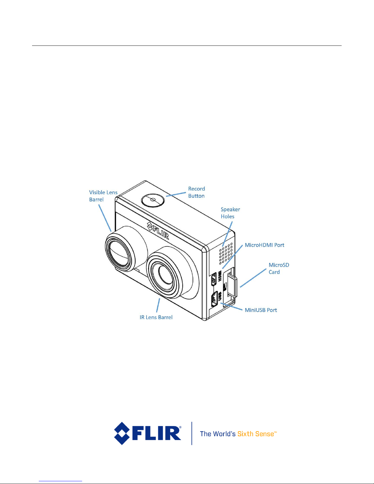
3.1.1 FLIR Duo Camera
Figure 1. Duo with Camera Mount
(32GB included)
Page 11
FLIR Duo Use r G u i d e
436-0100-01-10, Rev. 200 Duo User Guide
Information on this page is subject to change without notice
6
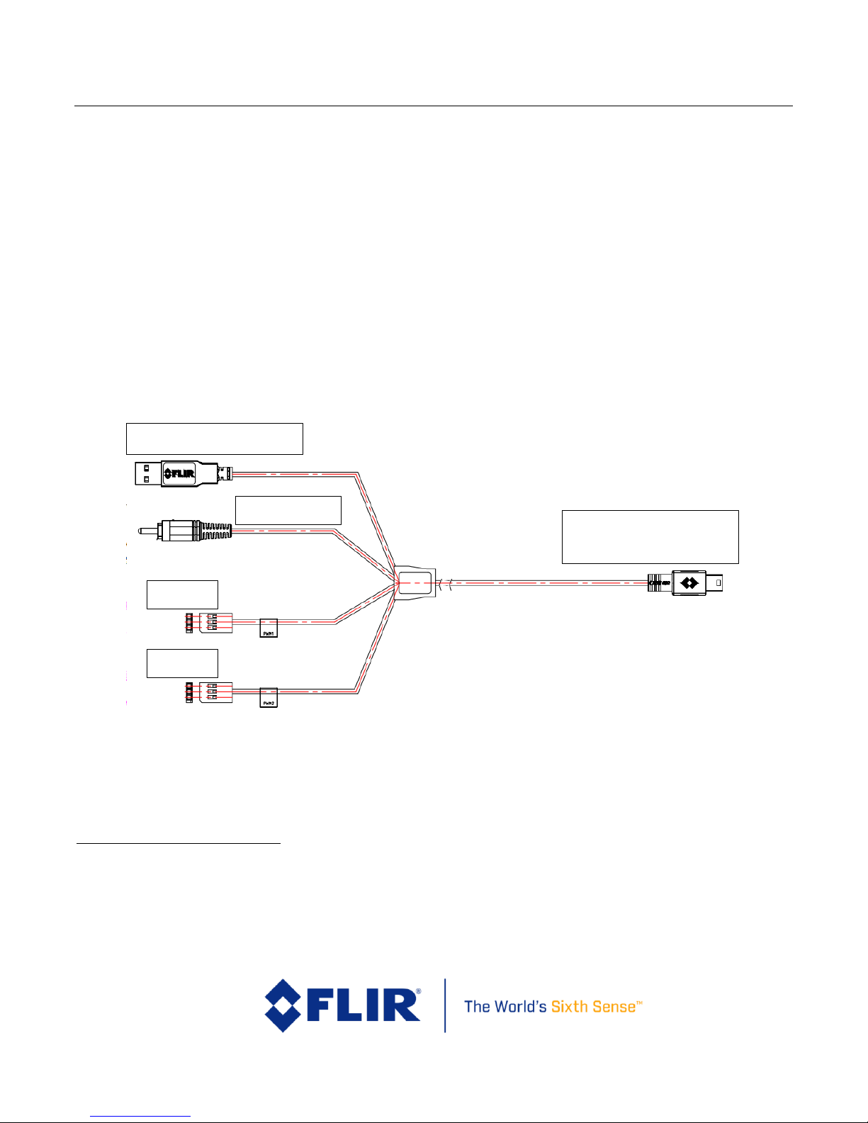
3.1.2 Bench Cable
The Bench Cable should be used for connecting the FLIR Duo to a computer USB port for power1
and file transfer, as well as video output testing with an analog video monitor. Analog video output
is accessed by connecting the yellow RCA pigtail to a video display. Digital video is not accessible
from the miniUSB port, but can be displayed using the microHDMI port.
The Bench Cable can also be used for connecting FLIR Duo to standard Radio/Control (R/C) Pulse
Width Modulation (PWM) outputs. See Table 1 for pin definitions.
Connecting to a MAVLink-compatible autopilot is possible by building a customized cable based on
accessing miniUSB pin1 and pin3 for MAVLink TX and RX. The MAVLink interface operates at a
default data rate of 57.6 kbps, with the ability to switch to 115.2 kbps, 230.4 kbps through the user
App. See Section 6 for more information.
Figure 2. Bench Cable
1
5 V, 0.44 A (average), 0.66 A (peak)
Camera 10-pin miniUSB port
Powered USB port
PWM2
PWM1
RCA Video
Page 12

FLIR Duo Use r G u i d e
436-0100-01-10, Rev. 200 Duo User Guide
Information on this page is subject to change without notice
7
4 Connecting to the Camera
This section describes the properties and methods of interfacing with the FLIR Duo, both
mechanically and through software.
4.1 Mechanical Interface
4.1.1 Size / Weight
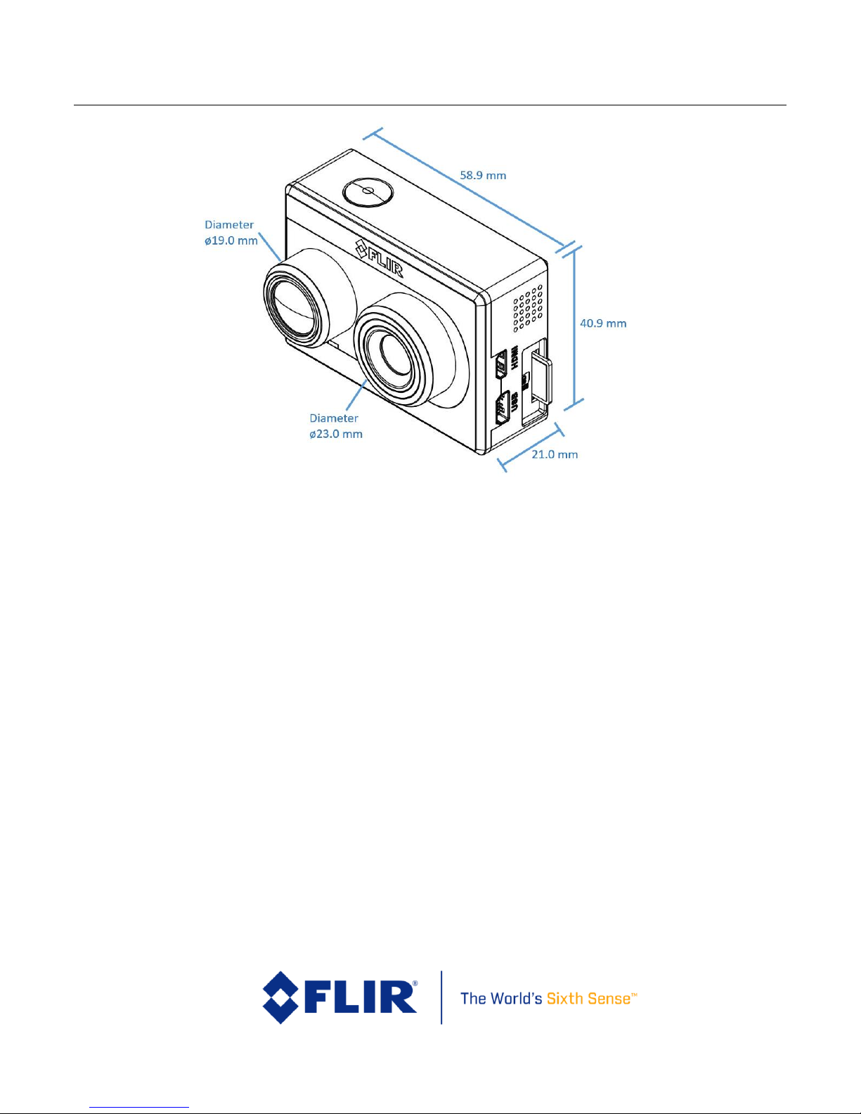
The overall size of the Duo is 58.9 mm x 40.9 mm x 30 mm (2.32 x 1.61 x 1.19 in), including the lens
but excluding cables and buttons (which protrude slightly). Weight is approximately 65 grams (2.3
oz.). These mechanical specifications do not take into account any additional mounting hardware.
For additional details, please see the Duo Technical Drawing referenced in Section 2.2.
4.1.2 Mounting
The Duo camera form-factor conveniently fits with most popular action-camera accessories: there
are many available commercial off-the-shelf (COTS) gimbals and mounts available for mounting the
Duo onto different UAS airframes. Refer to the Duo Technical Drawing for additional information.
Page 13
FLIR Duo Use r G u i d e
436-0100-01-10, Rev. 200 Duo User Guide
Information on this page is subject to change without notice
8
Figure 3. Core dimensions
4.2 Electrical Interface
4.2.1 Bench Testing
For initial bench testing, connect the 10-pin mini-USB connector on the Bench Cable (see Section
3.1.2) to the mini-USB port on the Duo camera. Connect the RCA plug on the Bench Cable to an
analog video monitor. Connect the USB (Type-A) connector on the Bench Cable to an available USB
port on your computer. Connect the PWM1 and PWM2 to a standard R/C PWM source, if needed. If
using an HDMI display, connect the camera to the display using an HDMI cable (not included). If
HDMI is used, the camera will automatically detect the connection and switch over to HDMI video
output.
4.2.2 Mini-USB Cables
FLIR Duo is compatible with many commercial off-the-shelf (COTS) 10-pin mini-USB cables that are
used to provide power to, and receive video from, action cameras commonly mounted on small
unmanned aerial systems (sUAS). The included bench cable is for initial setup and configuration of
the Duo. The internal wires of the FLIR bench cable are color coded to help you build a custom sUAS
Page 14
FLIR Duo Use r G u i d e
436-0100-01-10, Rev. 200 Duo User Guide
Information on this page is subject to change without notice
9
cable that can be used to integrate Duo to your airframe. Please refer to the Duo Technical Drawing
for electrical interface guidelines and USB connector pinout.
Simply plug the chosen cable into the mini-USB port on the FLIR Duo, connect power to an
appropriate filtered and regulated power supply, and video to a downlink, if desired. Approximate
operating current of the Duo camera is 440 mA at 5Vdc, (2.2 Watts). Peak current can reach as high
as 660 mA (3.3 Watts).
Note: FLIR Duo has over-voltage and reverse polarity protection on power pins. However,
exceeding the wide voltage specification (5-26 Vdc) will damage the camera and void the warranty.
Applying reverse polarity should not damage the unit, but it will prevent the camera for powering on
and is not recommended.
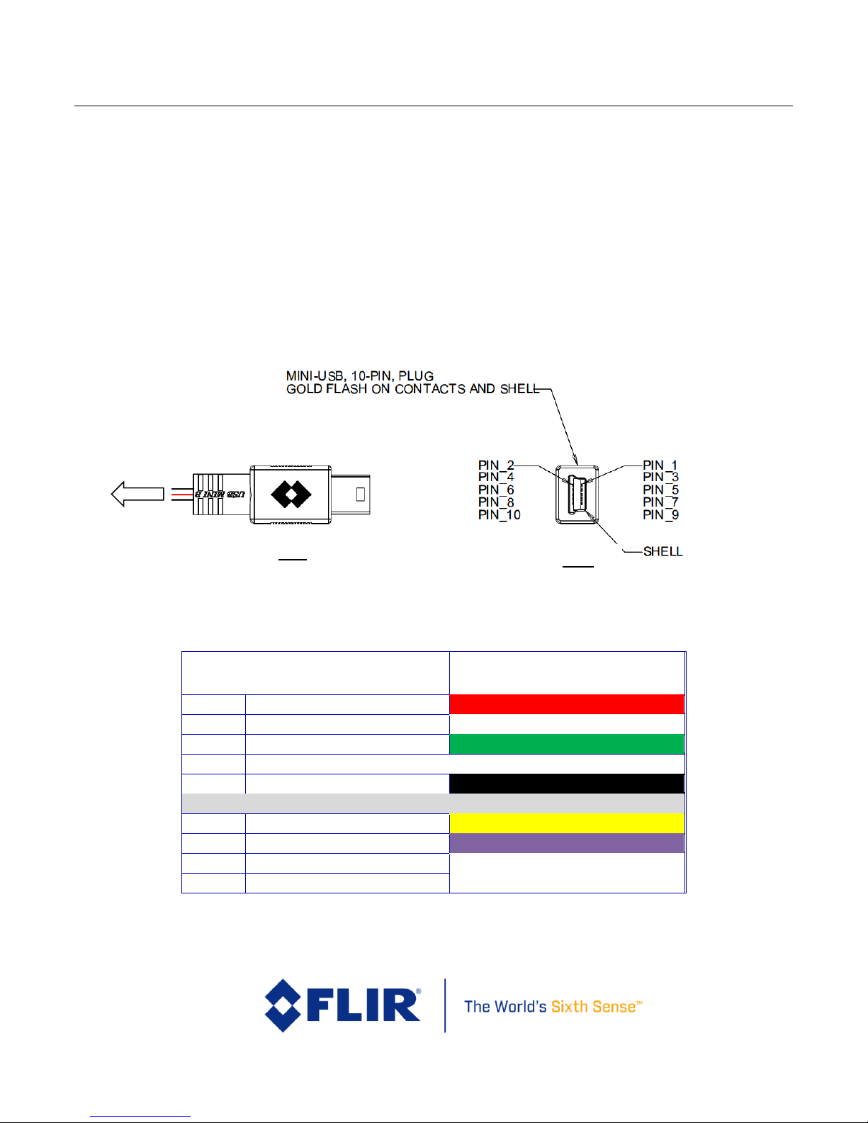
Figure 4: Mini-USB 10-pin Layout
Table 1: Mini-USB Port 10-pin Assignment
Mini-USB Port
Bench Cable Internal Wire Color
2
Main Power red
4
Data Low white
6
Data High green
8
Reserved
10
Main Power GND
black
1
PWM_1 / MAVLink TX Out
yellow
3
PWM_2 / MAVLink RX In
purple
5
Video Low
7
Video High
Top
Side
WIRING
Page 15
FLIR Duo Use r G u i d e
436-0100-01-10, Rev. 200 Duo User Guide
Information on this page is subject to change without notice
10
9
Reserved
4.3 Software Interface
The Duo camera is configured and operated through the FLIR UAS mobile device app. See Section 5
for additional details.
Note: The Duo camera is not compatible with the FLIR Camera Controller User Interface software.
When connected to the USB port on a computer, the camera appears as a mass storage device only.
There is no Software Developer’s Kit or API available for the camera. However, advanced camera
control can be arranged using PWM, MAVLink, or TCP/IP integration (see Section 6).
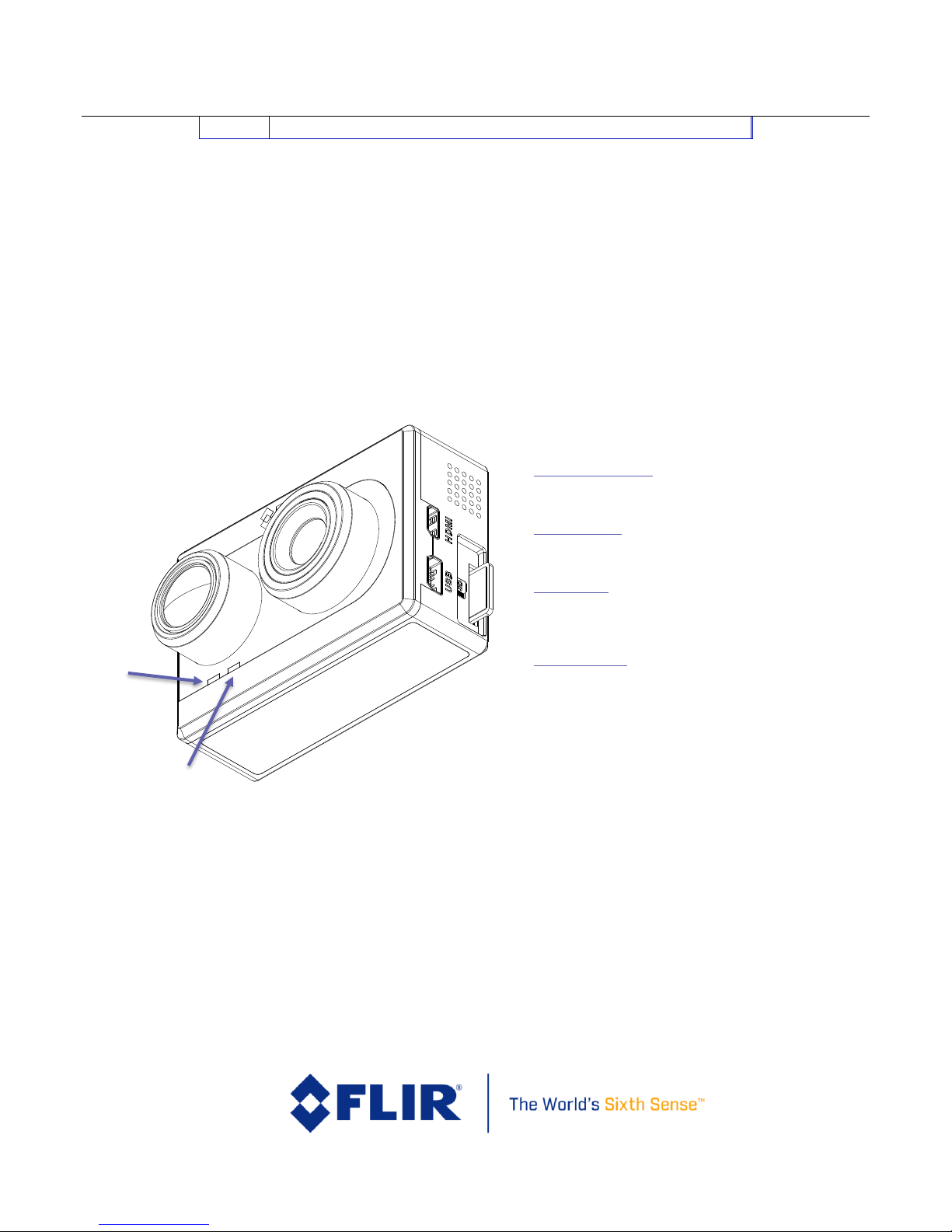
4.4 Camera Operation
Figure 5. Camera Status and Record LED Description
The Duo does not have an on/off switch. When power is applied the camera will boot automatically;
this takes less than 30 seconds.
When power is applied to the camera, the Status LED blinks red for approximately 20
seconds, then changes to solid blue, indicating that Bluetooth is enabled.
Record
LED
Status/Bluetooth
Booting /Powering Up
Record LED – Off and then Orange flashing
Status LED – Red flashing
Bluetooth Status
Status LED – Green for Bluetooth off
Status LED – Blue for Bluetooth on
Record ability
Record LED – Orange flashing: Unable to Record
Record LED – Green: Ready to Record
Record LED – Red flashing: Actively Recording
Firmware Update
Status LED – Purple flashing
Page 16

FLIR Duo Use r G u i d e
436-0100-01-10, Rev. 200 Duo User Guide
Information on this page is subject to change without notice
11
The Record LED will go from blinking orange to solid green, indicating that the camera is
ready for operation
o Note 1: If connected to a computer, the “Record” LED will continue blinking orange,
indicating that the device is in “USB Mass Storage” mode
o Note 2: If “Record” LED continues blinking orange while connected to a battery or
bench power supply, this indicates that there is no SD card in the camera
Launch the FLIR UAS app on your mobile device.
o Use the app to configure camera settings as desired
See Section 5 for information on camera settings & operating modes
o Disable the Bluetooth radio in preparation for flight
Simply press the Bluetooth button on the side of the Duo, and confirm that the
Status LED turns green
The Duo will automatically disable the Bluetooth radio after 2 minutes if no
commands are received from the app. It can be re-started by pressing the
Bluetooth button on the camera
Note: The Bluetooth interface is only intended for use during ground operations. FLIR does not
recommend flying while Bluetooth is enabled. Bluetooth interface has limited range and high latency.
Your FLIR Duo is now ready for use. Press the Record button on the camera or in the app to
start recording, or use PWM signals. The “Record” LED blinks red while recording video, or
flashes red each time it captures a still image.
4.5 Camera Troubleshooting
The Duo can be rebooted & reset to factory defaults through the FLIR UAS App
o With the App connected to the Duo, go to:
“Settings” -> “About” -> “Reset To Factory Defaults”
To reboot the system manually:
o Press and hold the “Record” button on the Duo for at least 5 seconds
To reboot and perform a factory reset to all default settings manually:
o Press and hold both the “Record” and “Bluetooth” buttons for 10 seconds
Page 17

FLIR Duo Use r G u i d e
436-0100-01-10, Rev. 200 Duo User Guide
Information on this page is subject to change without notice
12
5 The FLIR UAS App
The FLIR UAS app is the primary configuration interface for the Duo camera. It is compatible with
mobile devices equipped with Bluetooth LE running iOS 8.0 or later and Android V 4.3 or above. The
screenshots shown in this user manual are for the iOS App version; however, the menu system for
Android is quite similar.
Figure 6: FLIR launch screen
Page 18
FLIR Duo Use r G u i d e
436-0100-01-10, Rev. 200 Duo User Guide
Information on this page is subject to change without notice
13
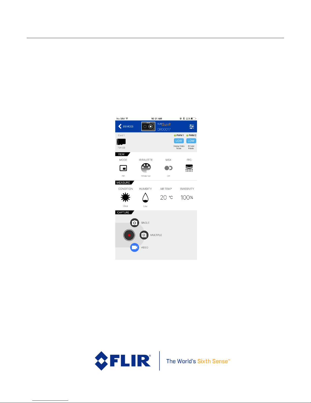
5.1 Home Screen
When launched, the FLIR UAS APP will automatically identify local FLIR UAS cameras; Confirm that
Bluetooth is enabled on your Duo device, then select the camera from the camera select screen. After
connecting to the camera, the Home screen will be displayed. The Home screen shows camera status
and allows the user to adjust the more frequently-used camera settings. The current PWM states
are also displayed at the top of the Home screen.
Note: The “Measure” section allows for control over parameters related to radiometry, and will only
appear for Duo R users.
Figure 7. Home Screen
Page 19

FLIR Duo Use r G u i d e
436-0100-01-10, Rev. 200 Duo User Guide
Information on this page is subject to change without notice
14
5.1.1 MSX
The Duo has the ability to enhance the IR imagery using FLIR’s patented MSX image blending
technology. Enable this feature to record real-time MSX-enhanced thermal imagery, or disable it to
record raw thermal image data. To activate, press the “Enable” or “Disable” text on the App, and
select the desired mode.
To adjust MSX settings, simply press the MSX bar on the App home screen to access the MSX dropdown menu.
Note: To record video with MSX enhancements, be sure to set the IR Video mode to H264. MSX will
not be recorded on 14-bit (TIFF Sequence) IR imagery, since this is recorded as raw video data.
5.1.1.1 MSX Strength
Use this feature to adjust the degree to which the MSX details show up in the IR imagery. A lower
setting results in a softer effect, while a higher setting results in a stronger effect.
5.1.1.2 Alignment
The “Horizontal Align” and “Vertical Align” features allow the user to adjust the alignment between
the visible image detail and the IR imagery with MSX enabled. Objects at different distances may
require slight tuning of the alignment settings to achieve an optimal image, particularly for objects
close to the camera.
5.1.1.2 Recommended MSX Alignment procedure
The MSX alignment adjustment can be used to optimize the MSX alignment for different use cases.
Objects at different distances will require slightly different alignment settings to achieve an ideal
image. The following method is a useful way to tune the MSX alignment prior to recording:
1) With the camera stationary, point at an easily-identifiable object at a distance similar to the
intended flight height.
a. For example, if you intend to fly at 20m above ground for a given video capture, focus
on an object 20m away
2) While viewing the IR image with MSX enabled on a display monitor, adjust the MSX
alignment settings to achieve optimal alignment for the test subject
3) Proceed with flight and data recording, and attempt to keep the Duo camera at the intended
flight height to obtain optimal MSX-enhanced imagery.
Page 20

FLIR Duo Use r G u i d e
436-0100-01-10, Rev. 200 Duo User Guide
Information on this page is subject to change without notice
15
5.1.2 IR Color Palette
The Duo detects and images long wave infrared radiation. Within the camera, this radiation is
mapped to a range of 255 colors. Using black and white palette, such as White Hot, this range is
converted to shades of gray with 0 being totally black and 255 being totally white. Different palettes
are available to change the appearance of the image. The most common selection is typically White
Hot (hotter objects appear lighter in color than cooler objects) or HotMetal (hotter objects appear
reddish white as oppose to cooler objects in the scene).
Figure 8. Thermal IR Color Palettes
There are two types of palettes offered in the Duo camera.
1. Linear: Scene radiation is mapped to pixel values where color is uniformly distributed from
one shade to another as pixel intensity increases. These palettes are the most common
palettes for general use. (WhiteHot & HotMetal palettes)
2. Contrast: Enhanced observed contrast by mapping pixel values to divergent color schemes.
Subtle differences between object temperatures become more apparent. (Rainbow palette)
Contrast
Linear
Page 21
FLIR Duo Use r G u i d e
436-0100-01-10, Rev. 200 Duo User Guide
Information on this page is subject to change without notice
16
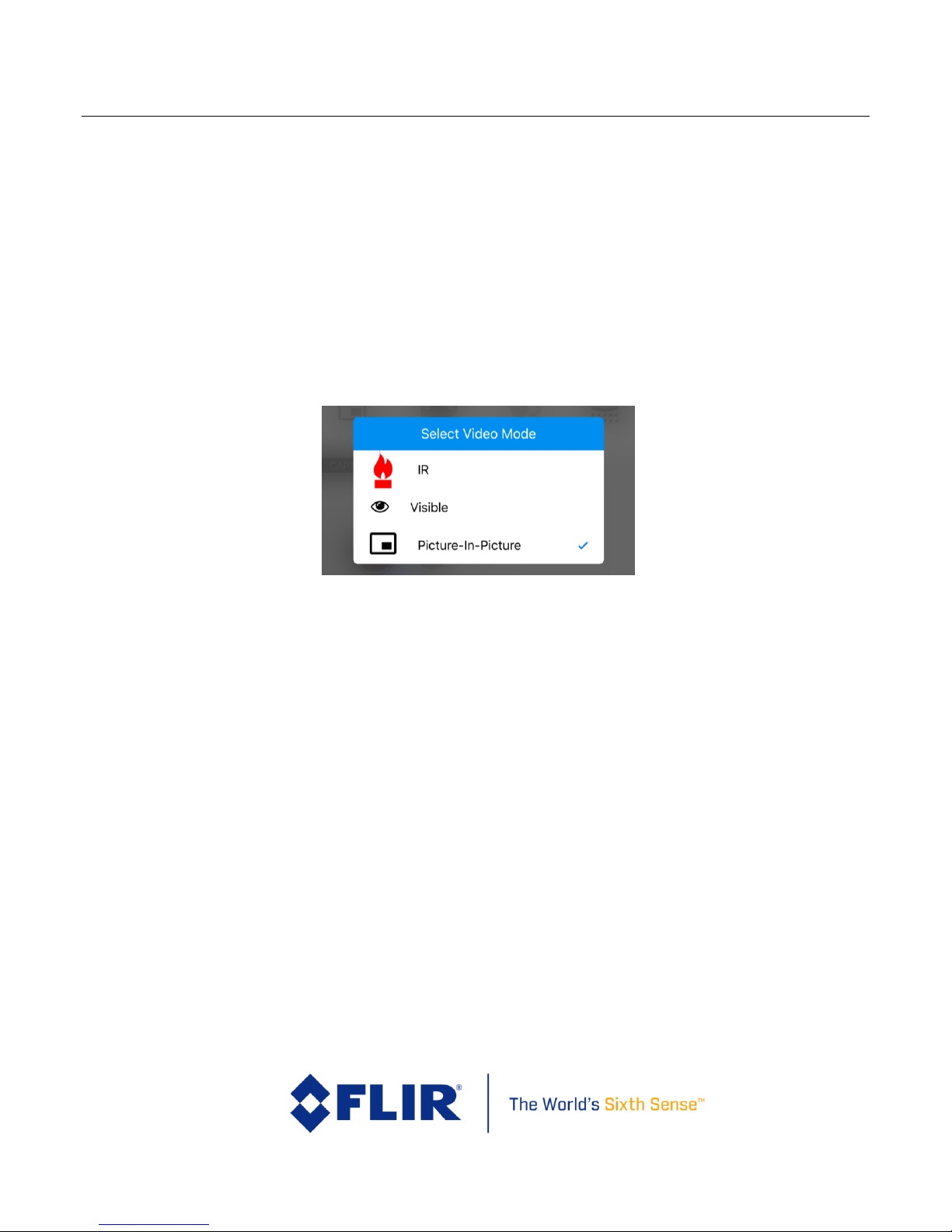
5.1.3 Display Video Mode
The Duo streams analog or HDMI video from the output ports. Selection of the display video mode
toggles between a Visible stream only, thermal infrared (IR) stream only, and a Picture-In-Picture
stream that shows both visible and thermal. Note that this setting does NOT impact what video is
recorded to disk – see the “Settings” -> “Main” -> “Recorded Video” setting for information on that
feature.
This feature will also impact the image thumbnail for the Radiometric JPEG file format: set to “IR”
to use the IR imagery as the thumbnail, or set to “Visible” or “Picture-In-Picture” for a visible image
thumbnail. Note that both IR & Visible image components are still recorded, and accessible through
FLIR Tools.
Figure 9. Video Display mode selection
Page 22
FLIR Duo Use r G u i d e
436-0100-01-10, Rev. 200 Duo User Guide
Information on this page is subject to change without notice
17
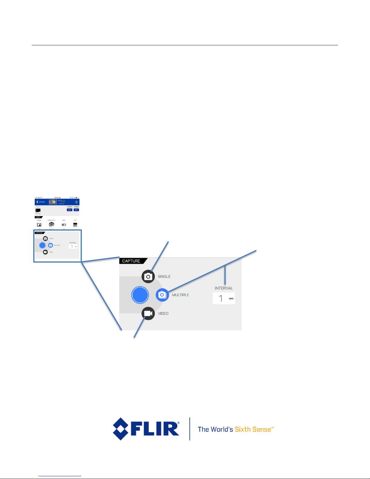
5.1.4 Video/Still Image
The Video and Still Images tabs configure the Duo recording mode. The system cannot capture a
still image during recording of video (or vice versa). The type of video or image files can be
configured in Settings.
5.1.4.1 Video
Video recordings can record either visible, infrared, or both simultaneously. File type settings are
adjustable in the Settings screen.
5.1.4.2 Still Images
Configures image capture at a user-selectable interval from one frame per second (slider setting of
“1s”) to one frame every 60 seconds (slider setting of “60s”). Duo can be configured to record visible
and IR as separate data files or as one combined FLIR Radiometric JPEG file.
Use the “Single” slider setting (far left) to record a single still image.
Figure 10: Video/Still Images and Record, shown in Still Images mode at 5-second intervals.
Video Recording Mode
Still Image Recording Mode
Image Interval Recording
Mode
Choose a capture
interval between
60 seconds (one
image every
minute) down to 1
second (one image
per second)
Page 23

FLIR Duo Use r G u i d e
436-0100-01-10, Rev. 200 Duo User Guide
Information on this page is subject to change without notice
18
5.1.5 Record
The “Record” button either captures a still image, or starts/stops live video
recording. See Section 7 for details on available file formats.
5.1.6 FFC (Recalibrate)
To maintain optimum performance, thermal imaging cameras must
occasionally perform an internal recalibration (also known as a Flat Field
Correction, or FFC). This is accomplished using an internal shutter, and takes
less than one second. During recalibration, a subtle audible “click” can be
heard, and live video is momentarily frozen. This function takes place
automatically (based on internal camera parameters), and can be manually
initiated through user command via the “Recalibrate” button on the home
screen, or through an appropriately-configured PWM channel.
Recalibrating prior to taking critical measurements will ensure the most
consistent image contrast.
Page 24
FLIR Duo Use r G u i d e
436-0100-01-10, Rev. 200 Duo User Guide
Information on this page is subject to change without notice
19
5.1.7 Settings
The “Settings” button is used to configure additional operational parameters
and camera modes.
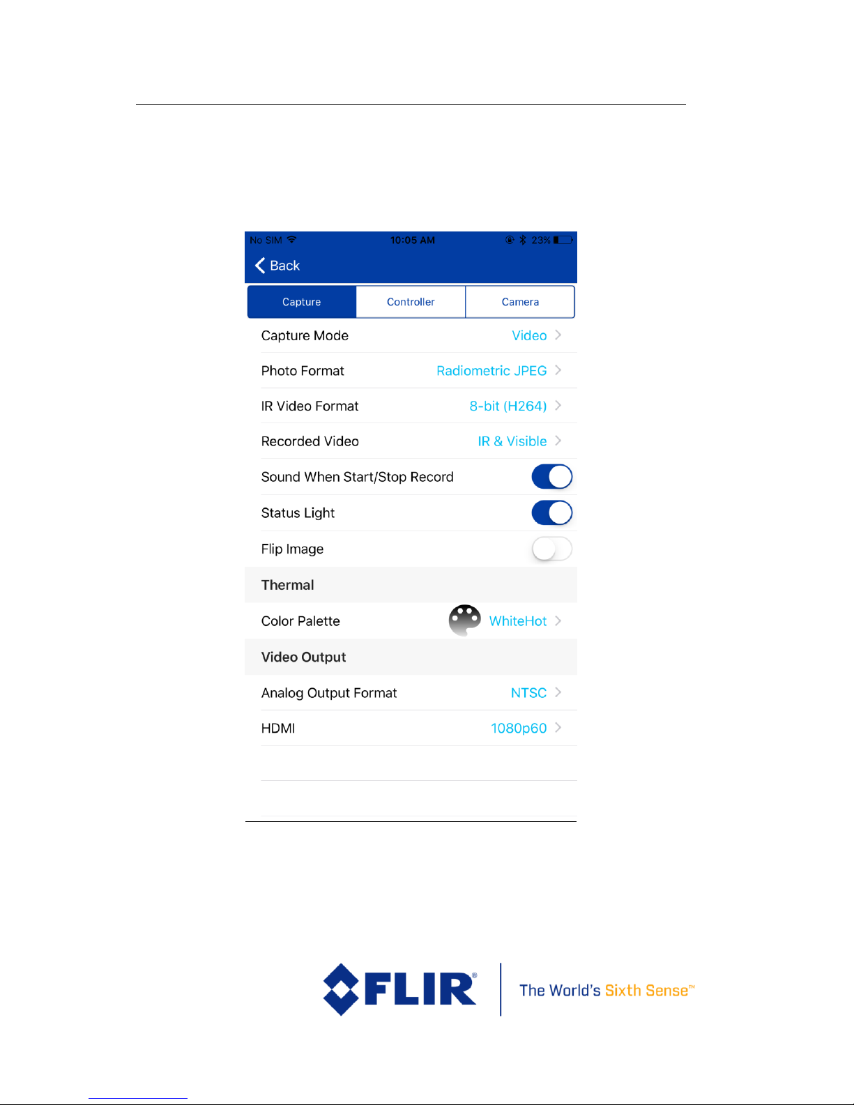
5.1.7.1 Main
Figure 11. Main Settings (Radiometry and Spot Meter function (Duo R only) not shown)
Page 25

FLIR Duo Use r G u i d e
436-0100-01-10, Rev. 200 Duo User Guide
Information on this page is subject to change without notice
20
Capture Mode: Select the recording mode: video, still, or multiple.
Photo Format: Select formats for still images and video saved to the
µSD card (See Section 7)
IR Video Format: Infrared video can be saved as 8-bit (H264) that
has FLIR AGC (automatic gain correction), MSX, Spot Meter (Duo R
only), and color palette applied, or 14-bit (TIFF Sequence) raw
sensor data. See Section 7 for more details.
Recorded Video: This setting determines the type of sensor data that
is saved to the µSD card. The Duo can be setup to record Visible Only,
IR Only, or IR & Visible.
Sound When Start/Stop Record: Turns on/off the audible indicator
for video recording. Even when turned off, the speaker will beep three
times when the camera is ready after power-up.
Status Light: Turns on/off the Status and Bluetooth LEDs. LED
indicators will still be displayed while camera is booting up, even if
this setting is turned off.
Camera Orientation Flip: Select image orientation. If the camera will
be mounted upside-down, enable this setting to vertically flip the
images recorded by the Duo.
Color Palette: Select the IR color palette
Radiometry (Duo R only): Enter the Radiometry parameter
adjustment menu
Spot Meter (Duo R only): Enable on-screen spot meter that shows
the temperature of the object in the center of the image
Analog Output Format: Select NTSC or PAL as the format of the video
that is output to the 10-pin mini USB port. This setting does not affect
the format of the video that is saved to the microSD card.
Page 26
FLIR Duo Use r G u i d e
436-0100-01-10, Rev. 200 Duo User Guide
Information on this page is subject to change without notice
21
HDMI: Select digital output stream format (through the microHDMI
port). Available options are 720p60 (60hz, 720p), 1080p30 (30hz,
1080p), and 1080p60 (60hz, 1080p). Note that this does not change
the actual recording frequency, only the display rate frequency when
connected to a digital monitor.
5.1.7.2 Accy. Port
See Section 6 for information on connecting via PWM and MAVLink.
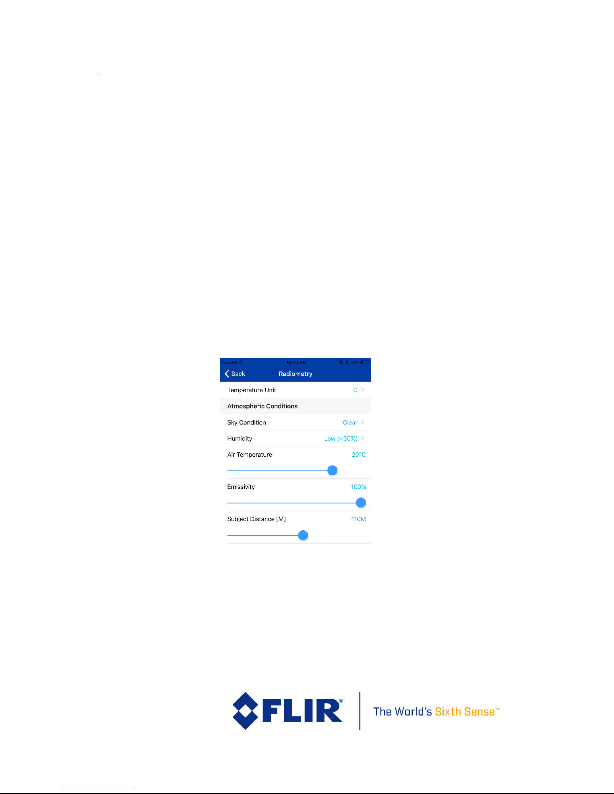
5.1.7.3 Radiometry
The Radiometry tab provides access to all the temperature measurement
functions and settings available on the Duo R. If connecting to a standard Duo
camera, this tab will not be visible and these features are unavailable. See
FLIR’s UAS Radiometry Tech Note (see Section 2.2 for the link) for a detailed
discussion on how to obtain accurate temperature readings for UAS
applications.
Figure 12. Radiometry Tab
Temperature Unit – Units of measure displayed on the analog video.
Select between Celsius and Fahrenheit.
Page 27
FLIR Duo Use r G u i d e
436-0100-01-10, Rev. 200 Duo User Guide
Information on this page is subject to change without notice
22
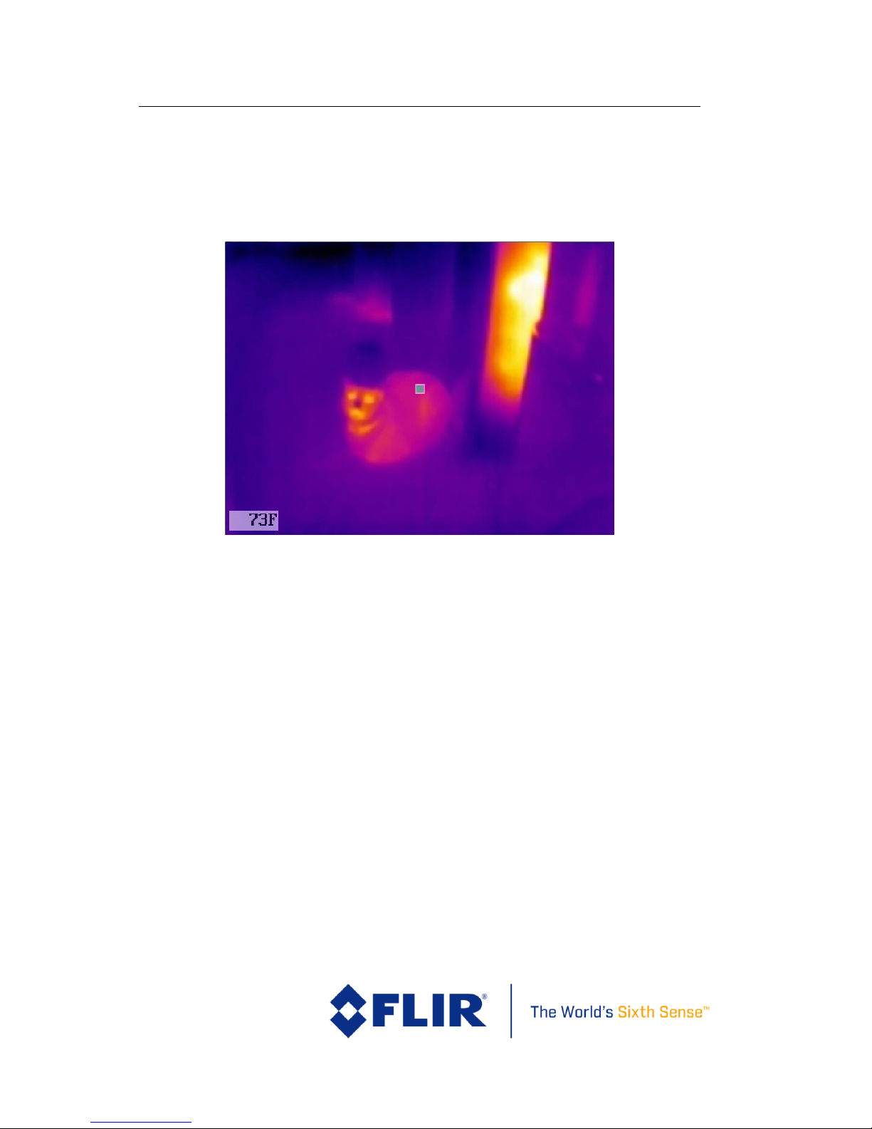
Spot Meter – Turns on or off the spot meter (fixed 4x4 pixel array) in
the center of the image and the digital temperature in the lower left
corner of the image.
Figure 13. Spot Meter OSD, with “Temperature Unit” set to Fahrenheit
Sky Condition – Measure of the cloud cover above the operating site.
This affects the background radiation incident on the scene. Choose
between Clear, Scattered, and Cloudy.
Humidity – Relative moisture content of the air. Three settings are
available; Low (<30%), Medium (~50%), High (>75%).
Air Temp. – Ambient temperature of the operating environment.
Values from 0 to 40° C (32 to 104° F) can be configured.
Emissivity – Measure of the target surface ability to emit thermal
energy. Values from 50-100% can be configured.
Subject Distance – Distance from the camera to the subject in the
scene. Values from 0-200m (0-218 yards) can be configured.
Page 28

FLIR Duo Use r G u i d e
436-0100-01-10, Rev. 200 Duo User Guide
Information on this page is subject to change without notice
23
5.1.7.3.1 Radiometry File Formats
The different available file formats have different characteristics with regards
to recording radiometric data, as follows:
- Video (8-bit H264) – If spot meter is enabled, this format will record the spot
meter reading from the center of the screen. This video is not editable for postprocessing
- Video (14-bit TIFF Sequence) – This video format will record temperature
values for every pixel. It can be processed using many different software tools,
such as FLIR Tools, ResearchIR, ImageJ, MATLAB, and others.
o To convert the pixel values to degrees Celsius, multiply the entire image
by 0.01 and then subtract 273.15
- Photo (Radiometric JPEG) – This photo format will record temperature values
for every pixel. It can be processed using FLIR Tools and ResearchIR
o A major benefit to this file format is that all radiometry parameters, such
as emissivity and subject distance, can be edited in post-processing. This
is not true for the TIFF file formats.
- Photo (14-bit TIFF) – This photo format will record temperature values for every
pixel.
o To convert pixel values to degrees Celsius, multiply the entire image by
0.01 and then subtract 273.15.
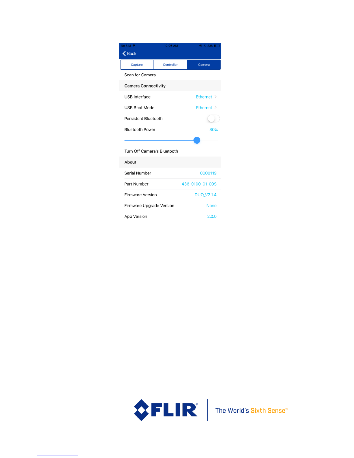
5.1.7.4 About
The “About” screen provides information on the current software installed on
the Duo, as well as the App version.
Page 29
FLIR Duo Use r G u i d e
436-0100-01-10, Rev. 200 Duo User Guide
Information on this page is subject to change without notice
24
Figure 14. About Page
Scan for Camera: Searches for any FLIR UAS camera in the area and
provides user ability to change cameras.
USB Interface: Use this setting to select between USB Mass Storage mode
(the default setting) and Ethernet mode. Recommended for advanced
users only – see section 6 for more detail on controlling the camera via a
virtual Ethernet connection.
USB Boot Mode: Sets which USB Interface mode the camera is defaulted
to upon power-on.
Persistent Bluetooth – Prevents the Bluetooth interface from shutting
off after 2 minutes by keeping the APP active.
Bluetooth Power – Adjusts the Bluetooth transmitter power and affects
the maximum range at which the Duo camera can connect to the mobile
device. Power values are expressed in percent.
Page 30

FLIR Duo Use r G u i d e
436-0100-01-10, Rev. 200 Duo User Guide
Information on this page is subject to change without notice
25
Turn Off Camera’s Bluetooth: Powers down the Bluetooth radio on the
camera. The camera will normally disable the Bluetooth after two minutes
of inactivity. See Persistent Bluetooth.
Serial No. – Serial number of the Duo camera currently connected to the
app. A “D” indicates a Duo, while a “DR” indicates a Duo R.
Part No. – FLIR part number of the Duo camera currently connected to
the app.
Firmware Version – Version of firmware currently loaded in the Duo
camera.
FW Upgrade Version - Detects if a camera upgrade file exists on the µSD
card. If one is available, the “Upgrade Available” dialog will start. Choose
“Continue” to begin the firmware upgrade process. See Appendix A for
details on how to upgrade camera firmware.
App Version - Version of software currently loaded on the mobile device.
App Upgrade Version – If the mobile device is connected to the Internet,
the Duo app will automatically search for any available app updates. If
one exists, the user will have the option to update by following the link to
the FLIR web page.
Terms and Conditions – Legal statements pertaining to the Duo product
and FLIR UAS App
Reset To Factory Defaults – Resets settings in the Duo camera to original
factory configuration. This is required during most FW updates as the
internal memory map will change as new features are added.
6 PWM, MAVLink, and TCP/IP Operation
6.1 PWM
6.1.1 Connecting to a PWM Compatible Flight Controller
The FLIR Duo camera is software- and connector-compatible with standard
R/C PWM controllers using the MiniUSB pinouts. An illustrative PWM
implementation connection is described in Table 2. Other flight controllers
or I/O modules may require different cables or connectors. Refer to the FLIR
Duo Technical Drawing for detailed information.
Page 31

FLIR Duo Use r G u i d e
436-0100-01-10, Rev. 200 Duo User Guide
Information on this page is subject to change without notice
26
Figure 15. PixHawk Flight Controller for PWM
Table 2: PWM Connection
MiniUSB Port
Bench Cable Internal
Wire Color
Aircraft Power
Source
P1 - AUX Out
(M20-1060300)2
P2 - AUX Out
(M20-1060300)
2
Main Power red
5-26 Vdc
10 Main Power GND
black
GND
1 PWM_1 yellow
PWM_1
1
10 GND black
GND 3 3 PWM_2 purple
PWM_2
1 10 GND black
GND 3
2
All cable plug part numbers are Hirose
MiniUSB
Pixhawk AUX PWM 1-6
Aircraft Power
Page 32

FLIR Duo Use r G u i d e
436-0100-01-10, Rev. 200 Duo User Guide
Information on this page is subject to change without notice
27
6.1.2 Configuring PWM Connection
Using the accessory port on the Duo and the included Bench Cable, camera functions can be
controlled directly from the sUAS flight controller via PWM signals (refer to the controller manual
for configuration instructions). Select the desired setting from the list of available PWM functions.
No two channels can be assigned to the same function. Any functions currently assigned to PWM
channels will not appear in the list of available functions for other channels.
To configure, select the “Settings” button on the Main page. Select the Accy. Port tab at the top of
the page. Ensure Serial Protocol is set to PWM. Select a PWM channel to configure (Figure 16).
Select the desired function. Select the number of states (Figure 17). The number of states will
depend on the type of switch that is being mapped on the flight controller. For a three-position
switch, the number of states will be three. Assign functions to the available states for each signal.
Next, program the flight controller to provide signals to the Aux Out ports for the PWM connectors
on the Bench Cable.
The Duo accepts standard PWM inputs for the R/C industry, 3.3-5vdc, 50Hz. LOW = 1ms/20ms,
MID = 1.5ms/20ms, HIGH = 2ms/20ms.
Figure 16. PWM Settings allow for control of Recording (start/stop and mode), IR Color Palette selection,
Recalibrate, and streaming Display Video Mode
Page 33

FLIR Duo Use r G u i d e
436-0100-01-10, Rev. 200 Duo User Guide
Information on this page is subject to change without notice
28
Figure 17. Function Selection
6.2 MAVLink
6.2.1 Connecting to a MAVLink Compatible Flight Controller
The FLIR Duo camera is compatible with many MAVLink autopilots using the MiniUSB pinouts,
illustrated in Figure 18 and Table 3. Other flight controllers or I/O modules may require different
cables or connectors. Refer to the FLIR Duo Technical Drawing for detailed information.
Page 34

FLIR Duo Use r G u i d e
436-0100-01-10, Rev. 200 Duo User Guide
Information on this page is subject to change without notice
29
Figure 18. PixHawk Flight Controller for MAVLink
Table 3: MAVLink Connection
MiniUSB Port
Bench Cable Internal
Wire Color
P2 - MAVLink
(DF13-6S-1.25C)3
2
Main Power
red 1
Main Power: 5 Vdc
10
Main Power GND
black
6
Main Power GND
1
MAVLink TX Out
yellow
3
MAVLink RX In
3
MAVLink RX In
purple
2
MAVLink TR Out
6.2.2 Configuring MAVLink Connection
Many UAS flight controllers support the MAVLink serial protocol to provide an interface with
external components. The Duo can be configured to use this bus to capture available telemetry data
provided by GPS, altimeter, accelerometers, etc. This data is saved as standard EXIF metadata in all
Still Image files. This data is not saved to Video files as there is no current standard for recording
3
All cable plug part numbers are Hirose
MiniUSB Port
Pixhawk AUX PWM 1-6
Page 35

FLIR Duo Use r G u i d e
436-0100-01-10, Rev. 200 Duo User Guide
Information on this page is subject to change without notice
30
video metadata. Metadata is accessible through standard photo editing applications, file explorers,
and suggested mapping applications.
The following MAVLink 3.0 messages are currently supported by the Duo FW 1.2.4 or newer:
Command
MAVLink
Message ID
R/S
(Receive
/ Send)
Notes
HEARTBEAT
0
R/S
PING
4
R/S*
If PING is received, then
will reply with a PING
SYSTEM_TIME
2 R
ATTITUDE
30 R
GLOBAL_POSITION_INT
33 R
GLOBAL_POSITION_INT_COV
63 R
HIL_GPS
113
R MOUNT_STATUS
158
R
Command
MAVLink
Component
ID
R/S
(Receive
/ Send)
Notes
MAV_COMP_ID_CAMERA
100
/
Command
MAVLink
Command
ID
R/S
(Receive
/ Send)
Notes
Page 36

FLIR Duo Use r G u i d e
436-0100-01-10, Rev. 200 Duo User Guide
Information on this page is subject to change without notice
31
MAV_CMD_DO_CONTROL_VIDEO
200
R
Custom FLIR parameters
MAV_CMD_DO_DIGICAM_CONFIGURE
202
R
Custom FLIR parameters
MAV_CMD_DO_DIGICAM_CONTROL
203
R
Custom FLIR parameters
MAV_CMD_IMAGE_START_CAPTURE
2000
R
Custom FLIR parameters
MAV_CMD_IMAGE_STOP_CAPTURE
2001
R MAV_CMD_VIDEO_START_CAPTURE
2500
R
Custom FLIR parameters
MAV_CMD_VIDEO_STOP_CAPTURE
2501
R MAV_CMD_USER_1
31010
R
Custom FLIR parameters
FLIR Duo communicates on the MAVLink bus at 57600 baud which is standard for most devices, as
default, but is configurable from the app. Where possible, ensure RTSCTS is disabled as this is known
to cause issues with communication. If all available flight controller ports are full, you may need to
investigate using a splitter cable to attach additional devices. Please refer to Table 1 for miniUSB
Port pin-out when building custom cables.
Duo can operate in a receive-only configuration much like an onscreen display (OSD), and therefore
does not require the TX pin from the camera to be connected to the RX pin on a flight controller.
Please note that all flight controllers will sleep a serial port if no connection is detected. The TX port
can only be disconnected when used in a Y-harness with a device providing a “heartbeat”.
Please see Appendix B for the full MAVLink protocol implementation.
6.2.3 Duo-specific Custom MAVLink Commands
In addition to the MAVLink commands listed above, the Duo camera supports certain customized
MAVLink commands to control various parameters of the camera. Experienced users familiar with
MAVLink can update the communication protocol on their Ground Station Controller to enable
greater in-flight control of the Duo camera.
Please see Appendix B for the custom MAVLink protocol implementation.
Page 37

FLIR Duo Use r G u i d e
436-0100-01-10, Rev. 200 Duo User Guide
Information on this page is subject to change without notice
32
6.3 TCP/IP
For all Duo FW versions 2.1.4 or later, the camera now supports a TCP/IP communication protocol
for command/control and small file transfer over USB.
To enable TCP/IP communication with your Duo, set “USB Interface” to “Ethernet” with the mobile
APP or over MAVlink, and then send commands from your host computer. The TCP/IP and MAVlink
interfaces can operate simultaneously, and provide complementary functionality in a fully
integrated system.
Please see Appendix C for the TCP/IP protocol implementation.
Page 38

FLIR Duo Use r G u i d e
436-0100-01-10, Rev. 200 Duo User Guide
Information on this page is subject to change without notice
33
7 File Formats
The Duo can save image data in a number of file formats.
7.1 Radiometric JPEG (FLIR Tools)
The Radiometric JPEG (RJPEG) format has both the compressed visible JPEG image and 14-bit raw
IR sensor data in a single file. Although this image can be viewed with any JPEG viewer, accessing
the full-data will require FLIR Tools or FLIR Research IR software. If the camera is setup for
MAVLink integration, telemetry will be captured and saved in standard metadata fields.
Figure 19: FLIR Tools can be used for advanced thermal analysis on Radiometric JPEGS
Page 39

FLIR Duo Use r G u i d e
436-0100-01-10, Rev. 200 Duo User Guide
Information on this page is subject to change without notice
34
7.2 JPEG
The JPEG format of the Duo stores the compressed visible image. This is the full-resolution visible
image that can be viewed with any JPEG viewer. If the camera is setup for MAVLink integration,
telemetry will be captured and saved in standard metadata fields.
7.3 TIFF, TIFF-Sequence
TIFF is uncompressed 14-bit raw IR sensor data with no post processing; radiometric count values
are recorded for each pixel. If the camera is setup for MAVLink integration, telemetry will be
captured and saved in standard metadata fields.
The following links provide information on viewing 14-bit TIFF images and TIFF-sequence videos.
Table 4: Visible Sensor Image Formats Recorded on microSD Card
File
Format
Feature
Use
Software
Visible Image
IR 8-bit
Colorized
Palette
IR
Raw
14-bit
AGC
Telemetry4
Visible Still Image File Type
JPEG √
√
Mapping,
Research
JPEG imaging tool
Visible Video File Type
MOV
(H.264) √
Reporting
Any video tool
4
Requires MAVLink integration
Page 40

FLIR Duo Use r G u i d e
436-0100-01-10, Rev. 200 Duo User Guide
Information on this page is subject to change without notice
35
Table 5: Thermal IR Sensor Image Formats Recorded on microSD Card
File
Format
Feature
Use
Software
Visible Image
IR 8-bit
Colorized
Palette
IR
Raw
14-bit
AGC
Telemetry5
Thermal IR Still Image File Type
RJPEG
√
√6 √ √
√
Reporting,
Research
FLIR Tools, FLIR
ResearchIR, any
image tool
TIFF
√
√
Mapping,
Research
Pix4D, Drone
Deploy, Matlab,
ImageJ
Thermal IR Video File Type
MOV
(H.264)
√ √
Reporting
Any video tool
TIFF-Seq
√
Mapping,
Research
FLIR ResearchIR,
Matlab, ImageJ
5
Requires MAVLink integration
6
IR 8-bit Thermal Colorized Recording only in Display Video Mode: IR. Always accessible using FLIR Software.
Page 41

FLIR Duo Use r G u i d e
436-0100-01-10, Rev. 200 Duo User Guide
Information on this page is subject to change without notice
36
7.4 Recommended Application Links
FLIR Tools: http://www.flir.com/instruments/display/?id=54865
FLIR ResearchIR: http://www.flir.com/Science/display/?id=51371
Pix4D: https://pix4d.com/
ImageJ: https://imagej.nih.gov/ij/download.html
MATLAB: http://www.mathworks.com/products/matlab/
o When using MATLAB it is recommended that the FLIR Atlas SDK is installed to expose the full
metadata set available from FLIR radiometric JPEG files: http://support.flir.com/resources/atlas-
matlab
Software Developers can access full metadata from FLIR radiometric JPEGs by integrating the Atlas SDK:
https://flir.custhelp.com/app/answers/detail/a_id/1043/kw/atlas%20sdk
Page 42

FLIR Duo Use r G u i d e
436-0100-01-10, Rev. 200 Duo User Guide
Information on this page is subject to change without notice
37
8 Care of FLIR Duo
Power your FLIR Duo with a regulated 5-26 Vdc power source. Using more than 26 Vdc will
damage the camera and void the warranty.
Do not touch the lens. If the lens gets dirty, a light dusting of air should dislodge any dust
particles. If the lens is still noticeably dirty, use 75% Isopropyl alcohol and lens tissue. Use
light wiping motions with a fresh section of lens tissue with each swipe so as not to drag dust
or dirt particles back over the lens surface.
FLIR Duo cameras have been focused at the factory and optimized for the maximum UAS
range. Opening the camera may compromise the external seal of the camera, and factory
focus will be lost. This also voids the camera warranty.
The FLIR Duo is neither water nor dust resistant. Care for it as you would any valuable piece
of electronics equipment.
If you have questions about your Duo camera, contact FLIR Tech Support
at 1-866-667-7732.
Page 43

FLIR Duo Use r G u i d e
436-0100-01-10, Rev. 200 Duo User Guide
Information on this page is subject to change without notice
38
Appendix A - Software and Firmware Update
How to Update App
Download the latest handset application from the appropriate web store for your platform. Some
handy links are listed below. Also be sure to keep the firmware and Mobile App up to date on your
device to receive continuous improvements.
iOS APP store (Web Link)
Android APP store (Web Link)
Android APK file direct DL (Web Link)
How to update Firmware (FW)
Please download the latest firmware from the FLIR web site here.
(http://www.flir.com/suas/duo/software)
Duo Firmware Upgrade Procedure
Instructions:
1) Connect to the Duo with the Bluetooth application and make note of all your settings. The
firmware upgrade will require resetting the camera settings to defaults.
2) Download the latest firmware update from http://www.flir.com/suas/duo/software
3) Connect the Duo to your computer via miniUSB
a) The Duo will appear as a removable storage device on your computer
b) Drag & drop latest firmware (.ITM file) onto the Duo camera
c) Connect to the Duo over Bluetooth via the FLIR UAS App
d) Follow the automated in-app prompts to update device FW
i. Do not restart camera during FW update
ii. This step can also be initiated through “Settings” -> “About” -> “FW Upgrade
Version”
e) After the device reboots, connect again over Bluetooth via the FLIR UAS App
4) Confirm that the correct FW has been uploaded by again viewing the “Settings” -> “About” tab.
Page 44

FLIR Duo Use r G u i d e
436-0100-01-10, Rev. 200 Duo User Guide
Information on this page is subject to change without notice
39
5) Restore User Settings. From your notes in Step 1 reconfigure any Main, Accessory Port, and
Radiometry (Duo R only) settings for your specific application. You can also delete the firmware
update file from your microSD card (it does not automatically delete itself).
Page 45

FLI R Du o U ser Gu ide
436-0100-01-10, Rev. 200 Duo User Guide
Information on this page is subject to change without notice
40
Appendix B - MAVLink Implementation
CMD ID
Field Name
Data
Type
Description (MAVlink published data)
FLIR Implementation
Device Implementation
FLIR Duo / R
0
HEARTBEAT
Shows the system is present and responding.
System ID
MAVlink packet Byte 3
Standard
1
Component ID
MAVlink packet Byte 4
Standard
100 Type
uint8_t
MAV_TYPE_GENERIC - Generic micro air vehicle.
Standard
0
Autopilot
uint8_t
MAV_AUTOPILOT_INVALID - No valid autopilot,
e.g. a GCS or other MAVLink component
Standard
8
Base Mode
uint8_t
MAV_MODE_FLAG_MANUAL_INPUT_ENABLED
- 0b01000000 remote control input is enabled.
Standard
64
Custom Mode
uint32_t
A bitfield for use for autopilot-specific flags.
Standard
0
System Status
uint8_t
MAV_STATE_ACTIVE - System is active and
might be already airborne. Motors are engaged.
Standard
4
MAVLink Version
uint8_t
MAVLink version, not writable by user
Standard
Standard
2
SYSTEM_TIME
System master clock time.
Time Unix
uint64_t
Timestamp of the master clock in microseconds
since UNIX epoch.
Standard
If time is valid, it will be set to the
device.
Time Boot
uint32_t
Timestamp of the component clock since boot time
in milliseconds.
Standard
Ignored
Page 46

FLI R Du o U ser Gu ide
436-0100-01-10, Rev. 200 Duo User Guide
Information on this page is subject to change without notice
41
4
PING
System latency diagnostics.
Time Unix
uint64_t
Timestamp (microseconds since UNIX epoch or
microseconds since system boot)
Standard
Ignored
Sequence
uint32_t
PING sequence
Standard
Standard
System ID
uint8_t
0: request ping from all receiving systems, if
greater than 0: message is a ping response and
number is the system id of the requesting system
Standard
See description above
Component ID
uint8_t
0: request ping from all receiving components, if
greater than 0: message is a ping response and
number is the system id of the requesting system
Standard
See description above
30
ATTITUDE
The attitude in the aeronautical frame.
Time Boot
uint32_t
Timestamp (milliseconds since system boot)
Ignored
Ignored
Roll
float
Roll angle (rad, -pi..+pi)
Metadata
MAV Roll
Pitch
float
Pitch angle (rad, -pi..+pi)
Metadata
MAV Pitch
Yaw
float
Yaw angle (rad, -pi..+pi)
Metadata
MAV Yaw
Roll Rate
float
Roll angular velocity (rad/s)
Metadata
MAV Roll Rate
Pitch Rate
float
Pitch angular velocity (rad/s)
Metadata
MAV Pitch Rate
Yaw Rate
float
Yaw angular velocity (rad/s)
Metadata
MAV Yaw Rate
33
GLOBAL_POSITION_INT
Filtered GPS position
Time Boot
uint32_t
Timestamp (milliseconds since system boot)
Ignored
Ignored
Latitude
int32_t
Latitude, expressed as * 1E7
Metadata
GPS Latitude
Longitude
int32_t
Longitude, expressed as * 1E7
Metadata
GPS Longitude
Altitude (MSL)
int32_t
Altitude in meters, expressed as * 1000
(millimeters), AMSL (not WGS84 - note that
virtually all GPS modules provide the AMSL as
well)
Metadata
GPS Altitude
Altitude (Relative)
int32_t
Altitude above ground in meters, expressed as *
1000 (millimeters)
Metadata
MAVRelativeAltitude
Page 47

FLI R Du o U ser Gu ide
436-0100-01-10, Rev. 200 Duo User Guide
Information on this page is subject to change without notice
42
Velocity X
int16_t
Ground X Speed (Latitude), expressed as m/s *
100
Metadata calculated
GPS Speed
Velocity Y
int16_t
Ground Y Speed (Longitude), expressed as m/s *
100
Metadata calculated
GPS Speed
Velocity Z
int16_t
Ground Z Speed (Altitude), expressed as m/s * 100
Metadata calculated
GPS Speed
Heading
uint16_t
Compass heading in degrees * 100, 0.0..359.99
degrees. If unknown, set to: UINT16_MAX
Metadata
GPS Track
63
GLOBAL_POSITION_INT_
COV
Higher resolution filtered GPS position
Time Boot
uint32_t
Timestamp (milliseconds since system boot)
Ignored
Ignored
Time Unix
uint64_t
Timestamp (microseconds since UNIX epoch) in
UTC. 0 for unknown.
Ignored
Ignored
estimator_type
uint8_t
Class id of the estimator this estimate originated
from.
Ignored
Ignored
Latitude
int32_t
Latitude, expressed as * 1E7
Metadata
GPS Latitude
Longitude
int32_t
Longitude, expressed as * 1E7
Metadata
GPS Longitude
Altitude (MSL)
int32_t
Altitude in meters, expressed as * 1000
(millimeters), AMSL (not WGS84 - note that
virtually all GPS modules provide the AMSL as
well)
Metadata
GPS Altitude
Altitude (Relative)
int32_t
Altitude above ground in meters, expressed as *
1000 (millimeters)
Metadata
MAVRelativeAltitude
Velocity X
float
Ground X Speed (Latitude), expressed as m/s *
100
Metadata
GPS Speed
Velocity Y
float
Ground Y Speed (Longitude), expressed as m/s *
100
Metadata
GPS Speed
Velocity Z
float
Ground Z Speed (Altitude), expressed as m/s * 100
Metadata
GPS Speed
covariance
float[36]
Covariance matrix (first six entries are the first
ROW, next six entries are the second row, etc.
Ignored
Ignored
113
HIL_GPS
RAW GPS from sensor
time_usec
uint64_t
Timestamp (microseconds since UNIX epoch or
microseconds since system boot)
Ignored
Ignored
Page 48

FLI R Du o U ser Gu ide
436-0100-01-10, Rev. 200 Duo User Guide
Information on this page is subject to change without notice
43
fix_type
uint8_t
0-1: no fix, 2: 2D fix, 3: 3D fix. Some applications
will not use the value of this field unless it is at least
two, so always correctly fill in the fix.
Ignored
Ignored
lat
int32_t
Latitude (WGS84), in degrees * 1E7
Metadata
GPS Latitude
lon
int32_t
Longitude (WGS84), in degrees * 1E7
Metadata
GPS Longitude
alt
int32_t
Altitude (AMSL, not WGS84), in meters * 1000
(positive for up)
Metadata
GPS Altitude
eph
uint16_t
GPS HDOP horizontal dilution of position in cm
(m*100). If unknown, set to: 65535
Metadata
GPSXYAccuracy
epv
uint16_t
GPS VDOP vertical dilution of position in cm
(m*100). If unknown, set to: 65535
Metadata
GPSZAccuracy
vel
uint16_t
GPS ground speed (m/s * 100). If unknown, set to:
65535
Ignored
Ignored
vn
int16_t
GPS velocity in cm/s in NORTH direction in earthfixed NED frame
Ignored
Ignored
ve
int16_t
GPS velocity in cm/s in EAST direction in earthfixed NED frame
Ignored
Ignored
vd
int16_t
GPS velocity in cm/s in DOWN direction in earthfixed NED frame
Ignored
Ignored
cog
uint16_t
Course over ground (NOT heading, but direction of
movement) in degrees * 100, 0.0..359.99 degrees.
If unknown, set to: 65535
Ignored
Ignored
satellites_visible
uint8_t
Number of satellites visible. If unknown, set to 255
Ignored
Ignored
158
MOUNT_STATUS
Orientation of gimbal
pointing_a
uint32_t
Pitch (deg*100)
Metadata
Yaw (camera)
pointing_b
uint32_t
Roll (deg*100)
Metadata
Pitch (camera)
pointing_c
uint32_t
Yaw (deg*100)
Metadata
Roll (camera)
Target System
uint8_t
System ID
Ignored
Ignored
Target Component
uint8_t
Component ID
Ignored
Ignored
Page 49

FLI R Du o U ser Gu ide
436-0100-01-10, Rev. 200 Duo User Guide
Information on this page is subject to change without notice
44
200
MAV_CMD_DO_CONTROL
_VIDEO
Control onboard camera system.
Adjust operational modes of FLIR
camera
Mission Param #1
float
Camera ID (-1 for all)
Standard
100
Mission Param #2
float
Transmission: 0: disabled, 1: enabled compressed,
2: enabled raw
Video signal made available to Analog
video or HDMI port
0 = IR
1 = VIS
2 = VIS with IR PIP
Mission Param #3
float
Transmission mode: 0: video stream, >0: single
images every n seconds (decimal)
Ignore
Ignored
Mission Param #4
float
Recording: 0: disabled, 1: enabled compressed, 2:
enabled raw
Video data to record to disk
0 = IR
1 = VIS
2 = IR and VIS
Mission Param #5
float
Empty
Ignored
Ignored
Mission Param #6
float
Empty
Ignored
Ignored
Mission Param #7
float
Empty
Ignored
Ignored
202
MAV_CMD_DO_DIGICAM_
CONFIGURE
Configure an on-board camera.
Adjust FLIR camera image modes
Mission Param #1
float
Modes: P, TV, AV, M, Etc
Set Scene (AGC) mode
Ignored
Mission Param #2
float
Shutter speed: Divisor number for one second
Set Color Palette
0 = HotMetal
1 = WhiteHot
2 = Rainbow
Mission Param #3
float
Aperture: F stop number
Set Scene ROI range
Ignored
Mission Param #4
float
ISO number e.g. 80, 100, 200, Etc
Set camera Gain Mode
Ignored
Mission Param #5
float
Exposure type enumerator
Rotate image 0 or 180 deg
0 = No rotation
1 = 180 deg rotation
Page 50

FLI R Du o U ser Gu ide
436-0100-01-10, Rev. 200 Duo User Guide
Information on this page is subject to change without notice
45
Mission Param #6
float
Command Identity
Set MSX function
0 = Disabled
1 = Enabled
Mission Param #7
float
Main engine cut-off time before camera trigger in
seconds/10 (0 means no cut-off)
Set MSX strength
0 thru 100, inclusive
203
MAV_CMD_DO_DIGICAM_
CONTROL
Control on-board camera.
Adjust FLIR camera image parameters
Mission Param #1
float
Session control e.g. show/hide lens
Command FFC
1 = Command FFC
Mission Param #2
float
Zoom's absolute position
Set eZoom level
Ignored
Mission Param #3
float
Zooming step value to offset zoom from the current
position
Ignored
Ignored
Mission Param #4
float
Focus Locking, Unlocking or Re-locking
Set Scene image tuning parameter 1
Ignored
Mission Param #5
float
Shooting Command
Set Scene image tuning parameter 2
Ignored
Mission Param #6
float
Command Identity
Set Scene image tuning parameter 3
Ignored
Mission Param #7
float
Empty
2000
MAV_CMD_IMAGE_STAR
T_CAPTURE
Start image capture sequence
Command Still image capture
Mission Param #1
float
Duration between two consecutive pictures (in
seconds)
Interval between captures
0 through 60, inclusive
Mission Param #2
float
Number of images to capture total - 0 for unlimited
capture
Ignored
Mission Param #3
float
Resolution in megapixels (0.3 for 640x480, 1.3 for
1280x720, etc)
FFF = FLIR File Format, also called
Radiometric JPEG
1 = JPEG & TIFF
2 = FFF
2001
MAV_CMD_IMAGE_STOP
_CAPTURE
Stop image capture sequence
Command Still stop capture
Mission Param #1
float
Reserved
Ignored
Ignored
Page 51

FLI R Du o U ser Gu ide
436-0100-01-10, Rev. 200 Duo User Guide
Information on this page is subject to change without notice
46
Mission Param #2
float
Reserved
Ignored
Ignored
2500
MAV_CMD_VIDEO_START
_CAPTURE
Starts video capture
Command Video capture
Mission Param #1
float
Camera ID (0 for all cameras), 1 for first, 2 for
second, etc.
Standard
Standard
Mission Param #2
float
Frames per second
Set video file type
1 = H264
2 = TIFF
Mission Param #3
float
Resolution in megapixels (0.3 for 640x480, 1.3 for
1280x720, etc)
Standard
Ignored
2501
MAV_CMD_VIDEO_STOP_
CAPTURE
Stop the current video capture
Command Video stop capture
Mission Param #1
float
Reserved
Ignored
Ignored
Mission Param #2
float
Reserved
Ignored
Ignored
31010
MAV_CMD_USER_1
User defined command
Set radiometric parameters
Mission Param #1
float
User Defined
Set temperature unit
0 = C
1 = F
Mission Param #2
float
User Defined
Set OSD temperature meter
0 = OFF
1 = Set SPOT_METER to 1
Mission Param #3
float
User Defined
Set Subject Emissivity
50 to 100, inclusive
-999 = Ignore
Mission Param #4
float
User Defined
Set Sky Condition
0 to 100, inclusive
-999 = Ignore
Mission Param #5
float
User Defined
Set Air Temperature
-50 to 327, inclusive
-999 = Ignore
Page 52

FLI R Du o U ser Gu ide
436-0100-01-10, Rev. 200 Duo User Guide
Information on this page is subject to change without notice
47
Mission Param #6
float
User Defined
Set Humidity
0 to 100, inclusive
-999 = Ignore
Mission Param #7
float
User Defined
Set Subject Range
0 to 2000, inclusive
-999 = Ignore
Page 53

FLI R Du o U ser Gu ide
436-0100-01-10, Rev. 200 Duo User Guide
Information on this page is subject to change without notice
48
Appendix C – TCP/IP Implementation
Data type definition
Type
identifier
Description
N.
Integer: int8_t, int16_t, int32_t, int64_t
N +
Positive integers: uint8_t, uint16_t, uint32_t, uint64_t
R
Float: float
C
Single character: char
S
String: string
Byte
Number of bytes ( 0 ~ 255 ): uchar
D
Date format string ( 20 17 - 01 - 01 ), Beijing time : string
T
Time format string ( 0 1 : 0 1 : 01 ), time in Beijing : string
DT
Date / time format string ( 20 17 - 01 - 01 0 1 : 0 1 : 01 ) , Beijing time: string
B
Boolean type ( 0 , 1 ): bool / b oolean
IP
IP address format string ( 192.168.2.208 ): string
UK
Not defined
Instruction Format
CSP uses the request / response mode. The request consists of a message header + message body.
1 Byte
1 Byte
2 Bytes
2 Bytes
2 Bytes
N Bytes
2 Bytes
Identification
code
status
code
Instruction
number
Instruction
length
CRC1
/ reserved
Instruction
body
CRC2
/ reserved
ID : default is 0x64
Status code : response status, request message can ignore the field. Is 0 for success, other representations error number
Instruction Number : Each instruction has a unique number
Instruction length : the length of the instruction body. If there is no instruction body, the length value is 0
Page 54

FLI R Du o U ser Gu ide
436-0100-01-10, Rev. 200 Duo User Guide
Information on this page is subject to change without notice
49
CRC1 / Reserved : Reserved field. In CSP-UART applications, for CRC check (from the beginning of the code, the checksum is calculated using the CRC16-
CCITT standard in bytes 1 to 6 ); this field can be ignored in CSP-TCP applications
message body: see the next chapter
CRC2 / Reserved : Reserved field. In CSP-UART applications, a CRC check (identification code from the beginning, in bytes . 1 ~ N + . 8 ) using CRC16-
CCITT standard checksum calculation ); in CSP-TCP applications can ignore this field
[Comment]: CRC16 polynomial = x
16
+ x
12
+ x 5 +1
Status Code
status code
Description
0x00
success
0x02
Operation error
0x03
The instruction number is incorrect
0x04
Parameter is illegal
0x05
CRC1 check code error
0x06
CRC2 check code error
0x07
The file could not be found
0x08
The device is busy and can not respond
Network Configuration
Network
Configuration
Description
IP address ( USB )
192.168.10.19
Control command
port
6000 , TCP short connection for camera control and parameter configuration, and
other messages
Event port
6002 , TCP long connection for camera event notification
【Note】:
Equipment as a server, network communication are used TCP request - response mode.
Page 55

FLI R Du o U ser Gu ide
436-0100-01-10, Rev. 200 Duo User Guide
Information on this page is subject to change without notice
50
Camera Control
3.1 Heartbeat
Heartbeat function, used to detect the camera online status, the proposed cycle of 5 ~ 10s .
Request instruction
Instruction Application: UART /
TCP
Data flow: G / A --- CS
Identification
code
1 Byte
status code
1 Byte
Instruction number
2 Bytes
Instruction length
2 Bytes
CRC1
/ reserved
2 Bytes
0x64
0x00
0x 0000
0x00
CRC
Instruction body
0 Bytes
CRC2
/ reserved
2 Bytes
air
CRC
CRC Description:
In CSP-TCP applications, the CRC is ignored
Response command:
Instruction Application: UART /
TCP
Data flow: CS --- G / A
Identification
code
1 Byte
status code
1 Byte
Instruction number
2 Bytes
Instruction length
2 Bytes
CRC1
/ reserved
2 Bytes
0x64
Status Code
0x0001
0x00
CRC
Instruction body
0 Bytes
CRC2
/ reserved
2 Bytes
air
C RC
CRC Description:
In CSP-TCP applications, the CRC is ignored
Page 56

FLI R Du o U ser Gu ide
436-0100-01-10, Rev. 200 Duo User Guide
Information on this page is subject to change without notice
51
3.2 Time synchronization
Time synchronization for other systems to synchronize the camera time.
Request instruction
Instruction Application: UART /
TCP
Data flow: G / A --- CS
Identification
code
1 Byte
status code
1 Byte
Instruction number
2 Bytes
Instruction length
2 Bytes
CRC1
/ reserved
2 Bytes
0x64
0x00
0x0002
0x08
CRC
Instruction body
8 Bytes
CRC2
/ reserved
2 Bytes
Instruction body format:
Struct {
String strD ateTime [20] ; // DT time format, such as 20 17 - 01 - 01 0 1 :
0 1 : 01
};
CRC
CRC Description:
In CSP-TCP applications, the CRC is ignored
Response command:
Instruction Application: UART /
TCP
Data flow: CS --- G / A
Identification
code
1 Byte
status code
1 Byte
Instruction number
2 Bytes
Instruction length
2 Bytes
CRC1
/ reserved
2 Bytes
0x64
Status Code
0x0003
0x00
CRC
Instruction body
0 Bytes
CRC2
/ reserved
2 B ytes
air
CRC
CRC Description:
In CSP-TCP applications, the CRC is ignored
Page 57

FLI R Du o U ser Gu ide
436-0100-01-10, Rev. 200 Duo User Guide
Information on this page is subject to change without notice
52
3.3 GPS information
Set the camera GPS information for the camera picture metadata to fill.
Request instruction
Instruction Application: UART /
TCP
Data flow: G / A --- CS
Identification
code
1 Byte
status code
1 Byte
Instruction number
2 Bytes
Instruction length
2 Bytes
CRC1
/ reserved
2 Bytes
0x64
0x00
0x0004
0x0C
CRC
Instruction body
12 Bytes
CRC2
/ reserved
2 Bytes
Instruction body format:
Struc t {
Int32_t s32 Longitude ; // Longitude * 1E7
Int32_t s32 Latitude ; // latitude * 1E7
Int32_t s32 Altitude ; // absolute elevation * 1000
};
CRC
CRC Description:
In CSP-TCP applications, the CRC is ignored
Response command:
no
3.4 Image display mode
3.4.1 query
Request instruction
Instruction Application: UART /
TCP
Data flow: G / A --- CS
Identification
code
1 Byte
status code
1 Byte
Instruction number
2 Bytes
Instruction length
2 Bytes
CRC1
/ reserved
2 Bytes
0x64
0x00
0x1000
0x00
CRC
Instruction body
0 Bytes
CRC2
/ reserved
Page 58

FLI R Du o U ser Gu ide
436-0100-01-10, Rev. 200 Duo User Guide
Information on this page is subject to change without notice
53
2 Bytes
air
CRC
CRC Description:
In CSP-TCP applications, the CRC is ignored
Response command:
Instruction Application: UART /
TCP
Data flow: CS --- G / A
Identification
code
1 Byte
status code
1 Byte
Instruction number
2 Bytes
Instruction length
2 Bytes
CRC1
/ reserved
2 Bytes
0x64
Status Code
0x1001
0x04
CRC
Instruction body
4 Bytes
CRC2
/ reserved
2 Bytes
Instruction body format:
Struct {
Uint8_t u8DisplayMode; // image display format,
see VIDEO_DISPLAY_MODE definition
Byte Reserve [3]; // Reserved
};
CRC
VIDEO_DISPLAY_MODE Definition:
Typedef enum {
VIDEO_DISPLAY_PIC_IN_PIC = 0,
VIDEO_DISPLAY_VISBLE = 1 ,
VIDEO_DISPLAY_IR = 2,
} VIDEO_DISPLAY_MODE;
CRC Description :
In CSP-TCP applications, the CRC is ignored
3.4.2 settings
Request instruction
Page 59

FLI R Du o U ser Gu ide
436-0100-01-10, Rev. 200 Duo User Guide
Information on this page is subject to change without notice
54
Instruction Application: UART /
TCP
Data flow: G / A --- CS
Identification
code
1 Byte
status code
1 Byte
Instruction number
2 Bytes
Instruction length
2 Bytes
CRC1
/ reserved
2 Bytes
0x64
0x00
0x1002
0x04
CRC
Instruction body
4 Bytes
CRC2
/ reserved
2 Bytes
Instruction body format:
Struc t {
Uint8_t u8DisplayMode; // image display format,
see VIDEO_DISPLAY_MODE definition
Byte Reserve [3]; // Reserved
};
CRC
VIDEO_DISPLAY_MODE Definition:
Typedef enum {
VIDEO_DISPLAY_PIC_IN_PIC = 0,
VIDEO_DISPLAY_VISBLE = 1,
VIDEO_DISPLAY_IR = 2,
} VIDEO_DISPLAY_MODE;
CRC Description :
In CSP-TCP applications, the CRC is ignored
Response command:
Instruction Application: UART /
TCP
Data flow: CS --- G / A
Identification
code
1 Byte
status code
1 Byte
Instruction number
2 Bytes
Instruction length
2 Bytes
CRC1
/ reserved
2 Bytes
0x64
Status Code
0x1003
0x00
CRC
Instruction body
0 Bytes
CRC2
/ reserved
Page 60

FLI R Du o U ser Gu ide
436-0100-01-10, Rev. 200 Duo User Guide
Information on this page is subject to change without notice
55
2 Bytes
air
CRC
CRC Description:
In CSP-TCP applications, the CRC is ignored
3.5 Recording status
3.5.1 query
Request instruction
Instruction Application: UART /
TCP
Data flow: G / A --- CS
Identification
code
1 Byte
status code
1 Byte
Instruction number
2 Bytes
Instruction length
2 Bytes
CRC1
/ reserved
2 Bytes
0x64
0x00
0x1004
0x00
CRC
Instruction body
0 Bytes
CRC2
/ reserved
2 Bytes
air
CRC
Description:
In CSP-TCP applications, the CRC is ignored
Response command:
Instruction Application: UART /
TCP
Data flow: CS --- G / A
Identification
code
1 Byte
status code
1 Byte
Instruction number
2 Bytes
Instruction length
2 Bytes
CRC1
/ reserved
2 Bytes
0x64
Status Code
0x1005
0x04
CRC
Instruction body
4 Bytes
CRC2
/ reserved
2 Bytes
Instruction body format:
Struct {
CRC
Page 61

FLI R Du o U ser Gu ide
436-0100-01-10, Rev. 200 Duo User Guide
Information on this page is subject to change without notice
56
U recording record, 0 - idle, 1 - recording, 2 - being
Byte Reserve [3]; // Reserved
}; CRC Description:
In CSP-TCP applications, the CRC is ignored
3.6 IR image color
3.6.1 query
Request instruction
Instruction Application: UART /
TCP
Data flow: G / A --- CS
Identification
code
1 Byte
status code
1 Byte
Instruction number
2 Bytes
Instruction length
2 Bytes
CRC1
/ reserved
2 Bytes
0x64
0x00
0x1008
0x00
CRC
Instruction body
0 Bytes
CRC2
/ reserved
2 Bytes
air
CRC
CRC Description:
In CSP-TCP applications, the CRC is ignored
Response command:
Instruction Application: UART /
TCP
Data flow: CS --- G / A
Identification
code
1 Byte
status code
1 Byte
Instruction number
2 Bytes
Instruction length
2 Bytes
CRC1
/ reserved
2 Bytes
0x64
Status Code
0x1009
0x04
CRC
Instruction body
4 Bytes
CRC2
/ reserved
2 Bytes
Instruction body format:
CRC
Page 62

FLI R Du o U ser Gu ide
436-0100-01-10, Rev. 200 Duo User Guide
Information on this page is subject to change without notice
57
Struct {
Uint8_t u8IRColor; // IR color, see IR_COLOR definition
Byte Reserve [3]; // Reserved
};
IR_COLOR Definition:
Typedef enum {
IR_COLOR_WHITEHOT = 0,
IR_COLOR_HOTMETAL = 1,
IR_COLOR_RAINBOW = 2,
} IR_COLOR;
CRC Description :
In CSP-TCP applications, the CRC is ignored
3.6.2 settings
Request instruction
Instruction Application: UART /
TCP
Data flow: G / A --- CS
Identification
code
1 Byte
status code
1 Byte
Instruction number
2 Bytes
Instruction length
2 Bytes
CRC1
/ reserved
2 Bytes
0x64
0x00
0x100A
0x04
CRC
Instruction body
4 Bytes
CRC2
/ reserved
2 Byt es
Instruction body format:
Struct {
Uint8_t u8IRColor; // IR color, see IR_COLOR definition
Byte Reserve [3]; // Reserved
};
CRC
IR_COLOR Definition:
Typedef enum {
IR_COLOR_WHITEHOT = 0,
IR_COLOR_HOTMETAL = 1,
IR_COLOR_RAINBOW = 2,
} IR_COLOR;
CRC Description :
Page 63

FLI R Du o U ser Gu ide
436-0100-01-10, Rev. 200 Duo User Guide
Information on this page is subject to change without notice
58
In CSP-TCP applications, the CRC is ignored
Response command:
Instruction Application: UART /
TCP
Data flow: CS --- G / A
Identification
code
1 Byte
status code
1 Byte
Instruction number
2 Bytes
Instruction length
2 Bytes
CRC1
/ reserved
2 Bytes
0x64
Status Code
0x100B
0x00
CRC
Instruction body
0 Bytes
CRC2
/ reserved
2 Bytes
air
CRC
Description:
In CSP-TCP applications, the CRC is ignored
3.7 HDMI output resolution
3.7.1 query
Request instruction
Instruction Application: UART /
TCP
Data flow: G / A --- CS
Identification
code
1 Byte
status code
1 Byte
Instruction number
2 Bytes
Instruction length
2 Bytes
CRC1
/ reserved
2 Bytes
0x64
0x00
0x100C
0x00
CRC
Instruction body
0 Bytes
CRC2
/ reserved
2 Bytes
air
CRC
CRC Description:
In CSP-TCP applications, the CRC is ignored
Response command:
Page 64

FLI R Du o U ser Gu ide
436-0100-01-10, Rev. 200 Duo User Guide
Information on this page is subject to change without notice
59
Instruction Application: UART /
TCP
Data flow: CS --- G / A
Identification
code
1 Byte
status code
1 Byte
Instruction number
2 Bytes
Instruction length
2 Bytes
CRC1
/ reserved
2 Bytes
0x64
Status Code
0x100D
0x04
CRC
Instruction body
4 Bytes
CRC2
/ reserved
2 Bytes
Instruction body format:
Struct {
Ureal8_t u8R esolution ; // output resolution, see HDMI_RESOLUTION definition
Byte Reserve [3]; // Reserved
};
CRC
HDMI_RESOLUTION Definition:
Typedef enum {
HDMI_RESOLUTION_720P30 = 0,
HDMI_RESOLUT ION_720P60 = 1,
HDMI_RESOLUTION_1080P30 = 2,
HDMI_RESOLUTION_1080P60 = 3,
} HDMI_RESOLUTION;
CRC Description :
In CSP-TCP applications, the CRC is ignored
3.7.2 settings
Request instruction
Instruction Application: UART /
TCP
Data flow: G / A --- CS
Identification
code
1 Byte
status code
1 Byte
Instruction number
2 Bytes
Instruction length
2 Bytes
CRC1
/ reserved
2 Bytes
0x64
0x00
0x100E
0x04
CRC
Instruction body
4 Bytes
CRC2
/ reserved
2 Bytes
Instruction body format:
CRC
Page 65

FLI R Du o U ser Gu ide
436-0100-01-10, Rev. 200 Duo User Guide
Information on this page is subject to change without notice
60
Struct {
Ureal8_t u8R esolution ; // output resolution, see HDMI_RESOLUTION definition
Byte Reserve [3]; // Reserved
};
HDMI_RESOLUTION Definition:
Typedef enum {
HDMI_RESOLUTION_720P30 = 0,
HDMI_RESOLUTION_720P60 = 1,
HDMI_RESOLUTION_1080 P30 = 2,
HDMI_RESOLUTION_1080P60 = 3,
} HDMI_RESOLUTION;
CRC Description :
In CSP-TCP applications, the CRC is ignored
Response command:
Instruction Application: UART /
TCP
Data flow: CS --- G / A
Identification
code
1 Byte
status code
1 Byte
Instruction number
2 Bytes
Instruction length
2 Bytes
CRC1
/ reserved
2 Bytes
0x64
Status Code
0x100F
0x00
CRC
Instruction body
0 Bytes
CRC2
/ reserved
2 Byte s
air
CRC
Description:
In CSP-TCP applications, the CRC is ignored
3.8 MSX edge enhancement
3.8.1 query
Request instruction
Instruction Application: UART /
TCP
Data flow: G / A --- CS
Identification
code
status code
1 Byte
Instruction number
2 Bytes
Instruction length
2 Bytes
CRC1
/ reserved
Page 66

FLI R Du o U ser Gu ide
436-0100-01-10, Rev. 200 Duo User Guide
Information on this page is subject to change without notice
61
1 Byte
2 Bytes
0x64
0x00
0x1010
0x00
CRC
Instruction body
0 Bytes
CRC2
/ reserved
2 Bytes
air
CRC
CRC Description:
In CSP-TCP applications, the CRC is ignored
Response command:
Instruction Application: UART /
TCP
Data flow: CS --- G / A
Identification
code
1 Byte
status code
1 Byte
Instruction number
2 Bytes
Instruction length
2 Bytes
CRC1
/ reserved
2 Bytes
0x64
Status Code
0x1011
0x04
CRC
Instruction body
4 Bytes
CRC2
/ reserved
2 Bytes
Instruction body format:
Struct {
BOOL bEnable ; // the MSX enabled, 1- open, 0- off
UX8S trength ; // MSX strength, 0 ~ 100
Int8_t s8PosX; // MSX X coordinates , -100 ~ 100
Int8_t s8PosY; // MSX X coordinates , -8 ~ 8
};
CRC
CRC Description :
In CSP-TCP applications, the CRC is ignored
3.8.2 settings
Request instruction
Instruction Application: UART /
TCP
Data flow: G / A --- CS
Identification
code
status code
1 Byte
Instruction number
2 Bytes
Instruction length
2 Bytes
CRC1
/ reserved
Page 67

FLI R Du o U ser Gu ide
436-0100-01-10, Rev. 200 Duo User Guide
Information on this page is subject to change without notice
62
1 Byte
2 Bytes
0x64
0x0 0
0x1012
0x04
CRC
Instruction body
4 Bytes
CRC2
/ reserved
2 Bytes
Instruction body format:
Struct {
BOOL bEnable ; // the MSX enabled, 1- open, 0- off
UX8S trength ; // MSX strength, 0 ~ 100
Int8_t s8PosX; // MSX X coordinates , -100 ~ 100
Int8_t s8PosY; // MSX X coordinates , -8 ~ 8
};
CRC
CRC Description :
In CSP-TCP applications, the CRC is ignored
Response command:
Instruction Application: UART /
TCP
Data flow: CS --- G / A
Identification
code
1 Byte
status code
1 Byte
Instruction number
2 Bytes
Instruction length
2 Bytes
CRC1
/ reserved
2 Bytes
0x64
Status Code
0x1013
0x00
CRC
Instruction body
0 Bytes
CRC2
/ reserved
2 Bytes
air
CRC
Description:
In CSP-TCP applications, the CRC is ignored
3.9 SD card
3.9.1 Status information
Information query for the specified SD card, including capacity, status.
Request instruction
Instruction Application: UART /
TCP
Data flow: G / A --- CS
Page 68

FLI R Du o U ser Gu ide
436-0100-01-10, Rev. 200 Duo User Guide
Information on this page is subject to change without notice
63
Identification
code
1 Byte
status code
1 Byte
Instruction number
2 Bytes
Instruction length
2 Bytes
CRC1
/ reserved
2 Bytes
0x64
0x00
0x1014
0x04
CRC
Instruction body
4 Bytes
CRC2
/ reserved
2 Bytes
Instruction body format:
Struct {
uint8_t u8SDcardNo; // SD card number, from 1 to start
Byte Reserve [3]; // Reserved
};
CRC
CRC Description :
In CSP-TCP applications, the CRC is ignored
Response command:
Instruction Application: UART /
TCP
Data flow: CS --- G / A
Identification
code
1 Byte
status code
1 Byte
Instruction number
2 Bytes
Instruction length
2 Bytes
CRC1
/ reserved
2 Bytes
0x64
Status Code
0x1015
0x0C
CRC
Instruction body
12 Bytes
CRC2
/ reserved
2 Bytes
Instruction body format:
Struct {
uint8_t u8SDcardNo; // SD card number, from 1 to start
// SD card status, 0 - available 1 nonexistent 2 - card full 3 - exception 4 - format
error or format unrecognizable
Byte Reserve [2]; // Reserved
Uint32_t u32 Total ; // total capacity in megabytes
Uint32_t u32Free; // remaining capacity in megabytes
};
CRC
Description:
Page 69

FLI R Du o U ser Gu ide
436-0100-01-10, Rev. 200 Duo User Guide
Information on this page is subject to change without notice
64
In CSP-TCP applications, the CRC is ignored
3.9.2 formatting
Format the specified SD card.
Request instruction
Instruction Application: UART /
TCP
Data flow: G / A --- CS
Identification
code
1 Byte
status code
1 Byte
Instruction number
2 Bytes
Instruction length
2 Bytes
CRC1
/ reserved
2 Bytes
0x64
0x00
0x1016
0x04
CRC
Instruction body
4 Bytes
CRC2
/ reserved
2 Bytes
Instruction body format:
Struct {
uint8_t u8SDcardNo; // SD card number, from 1 to start
Byte Reserve [3]; // Reserved
};
CRC
CRC Description :
In CSP-TCP applications, the CRC is ignored
Response command:
Instruction Application: UART /
TCP
Data flow: CS --- G / A
Identification
code
1 Byte
status code
1 Byte
Instruction number
2 Bytes
Instruction length
2 Bytes
CRC1
/ reserved
2 Bytes
0x64
Status Code
0x1017
0x00
CRC
Instruction body
0 Bytes
CRC2
/ reserved
2 Bytes
air
CRC
Description:
Page 70

FLI R Du o U ser Gu ide
436-0100-01-10, Rev. 200 Duo User Guide
Information on this page is subject to change without notice
65
In CSP-TCP applications, the CRC is ignored
3.10 LED enabled
3.10.1 query
Request instruction
Instruction Application: UART /
TCP
Data flow: G / A --- CS
Identification
code
1 Byte
status code
1 Byte
Instruction number
2 Bytes
Instruction length
2 Bytes
CRC1
/ reserved
2 Bytes
0x64
0x00
0x101A
0x00
CRC
Instruction body
0 Bytes
CRC2
/ reserved
2 Bytes
air
CRC
CRC Description :
In CSP-TCP applications, the CRC is ignored
Response command:
Instruction Application: UART /
TCP
Data flow: CS --- G / A
Identification
code
1 Byte
status code
1 Byte
Instruction number
2 Bytes
Instruction length
2 Bytes
CRC1
/ reserved
2 Bytes
0x64
Status Code
0x101B
0x04
CRC
Instruction body
4 Bytes
CRC2
/ reserved
2 Bytes
Instruction body format:
Struct {
BOOL bEnable; 0- // Close 1- opening
Byte Reserve [3]; // Reserved
};
CRC
CRC Description :
Page 71

FLI R Du o U ser Gu ide
436-0100-01-10, Rev. 200 Duo User Guide
Information on this page is subject to change without notice
66
In CSP-TCP applications, the CRC is ignored
3.10.2 settings
Request instruction
Instruction Application: UART /
TCP
Data flow: G / A --- CS
Identification
code
1 Byte
status code
1 Byte
Instruction number
2 Bytes
Instruction length
2 Bytes
CRC1
/ reserved
2 Bytes
0x64
0x00
0x101C
0x04
CRC
Instruction body
4 Bytes
CRC2
/ reserved
2 Bytes
Instruction body format:
Struct {
BOOL bEnable; 0- // Close 1- opening
Byte Reserve [3]; // Reserved
};
CRC
CRC Description :
In CSP-TCP applications, the CRC is ignored
Response command:
Instruction Application: UART /
TCP
Data flow: CS --- G / A
Identification
code
1 Byte
status code
1 Byte
Instruction number
2 Bytes
Instruction length
2 Bytes
CRC1
/ reserved
2 Bytes
0x64
Status Code
0x101D
0x00
CRC
Instruction body
0 Bytes
CRC2
/ reserved
2 Bytes
air
CRC
CRC Description :
In CSP-TCP applications, the CRC is ignored
3.11 TONES enabled
Page 72

FLI R Du o U ser Gu ide
436-0100-01-10, Rev. 200 Duo User Guide
Information on this page is subject to change without notice
67
3.11.1 query
Request instruction
Instruction Application: UART /
TCP
Data flow: G / A --- CS
Identification
code
1 Byte
status code
1 Byte
Instruction number
2 Bytes
Instruction length
2 Bytes
CRC1
/ reserved
2 Bytes
0x64
0x00
0x101E
0x00
CRC
Instruction body
0 Bytes
CRC2
/ reserved
2 Bytes
air
CRC
CRC Description :
In CSP-TCP applications, the CRC is ignored
Response command:
Instruction Application: UART /
TCP
Data flow: CS --- G / A
Identification
code
1 Byte
status code
1 Byte
Instruction number
2 Bytes
Instruction length
2 Bytes
CRC1
/ reserved
2 Bytes
0x 64
Status Code
0x101F
0x04
CRC
Instruction body
4 Bytes
CRC2
/ reserved
2 Bytes
Instruction body format:
Struct {
BOOL bEnable; 0- // Close 1- opening
Byte Reserve [3]; // Reserved
};
CRC
CRC Description :
In CSP-TCP applications, the CRC is ignored
3.11.2 settings
Request instruction
Page 73

FLI R Du o U ser Gu ide
436-0100-01-10, Rev. 200 Duo User Guide
Information on this page is subject to change without notice
68
Instruction Application: UART /
TCP
Data flow: G / A --- CS
Identification
code
1 Byte
status code
1 Byte
Instruction number
2 By tes
Instruction length
2 Bytes
CRC1
/ reserved
2 Bytes
0x64
0x00
0x1020
0x04
CRC
Instruction body
4 Bytes
CRC2
/ reserved
2 Bytes
Instruction body format:
Struct {
BOOL bEnable; 0- // Close 1- opening
Byte Reserve [3]; // Reserved
};
CRC
CRC Description :
In CSP-TCP applications, the CRC is ignored
Response command:
Instruction Application: UART /
TCP
Data flow: CS --- G / A
Identification
code
1 Byte
status code
1 Byte
Instruction number
2 Bytes
Instruction length
2 Bytes
CRC1
/ reserved
2 Bytes
0x64
Status Code
0x1021
0x00
CRC
Instruction body
0 Bytes
CRC2
/ reserved
2 Bytes
air
CRC
CRC Description :
In CSP-TCP applications, the CRC is ignored
3.12 PIP position
3.12.1 query
Request instruction
Page 74

FLI R Du o U ser Gu ide
436-0100-01-10, Rev. 200 Duo User Guide
Information on this page is subject to change without notice
69
Instruction Application: UART /
TCP
Data flow: G / A --- CS
Identification
code
1 Byte
status code
1 Byte
Instruction number
2 Bytes
Instruction length
2 Bytes
CRC1
/ reserved
2 Bytes
0x64
0x00
0x1022
0x00
CRC
Instruction body
0 Bytes
CRC2
/ reserved
2 Bytes
air
CRC
CRC Description :
In CSP-TCP applications, the CRC is ignored
Response command:
Instruction Application: UART /
TCP
Data flow: CS --- G / A
Identification
code
1 Byte
status code
1 Byte
Instruction number
2 Bytes
Instruction length
2 Bytes
CRC1
/ reserved
2 Bytes
0x64
Status Code
0x1023
0x04
CR C
Instruction body
4 Bytes
CRC2
/ reserved
2 Bytes
Instruction body format:
Struct {
u8P uint8_t osition ; // see PIP_POSITION defined
Byte Reserve [3]; // Reserved
};
CRC
PIP_POSITION Definition:
Typedef enum {
LEFT_UP = 0,
MIDDLE_UP,
RIGHT_UP,
LEFT_MIDDLE,
CENTRAL,
Page 75

FLI R Du o U ser Gu ide
436-0100-01-10, Rev. 200 Duo User Guide
Information on this page is subject to change without notice
70
RIGHT_MID DLE,
LEFT_DOWN,
MIDDLE_DOWN,
RIGHT_DOWN
} PIP_POSITION;
CRC Description :
In CSP-TCP applications, the CRC is ignored
3.12.2 settings
Request instruction
Instruction Application: UART /
TCP
Data flow: G / A --- CS
Identification
code
1 Byte
status code
1 Byte
Instruction number
2 Bytes
Instruction length
2 Bytes
CRC1
/ reserved
2 Bytes
0x64
0x00
0x1024
0x04
CRC
Instruction body
4 Bytes
CRC2
/ reserved
2 Bytes
Instruction body format:
Struct {
u8P uint8_t osition ; // see PIP_POSITION defined
Byte Reserve [3]; // Reserved
};
CRC
PIP_POSITION Definition:
Typedef enum {
LEFT_UP = 0,
MIDDLE_UP,
RIGHT_UP,
LEFT_MIDDLE,
CENTRAL,
RIGHT_MIDDLE,
LEFT_DOWN,
MIDDLE_DOWN,
RIGHT_DOWN
} PIP_POSITION;
Page 76

FLI R Du o U ser Gu ide
436-0100-01-10, Rev. 200 Duo User Guide
Information on this page is subject to change without notice
71
CRC Description :
In CSP-TCP applications, the CRC is ignored
Response command:
Instruction Application: UART /
TCP
Data flow: CS --- G / A
Identification
code
1 Byte
status code
1 Byte
Instruction number
2 Bytes
Instruction length
2 Bytes
CRC1
/ reserved
2 Bytes
0x64
Status Code
0x1025
0x00
CRC
Instruction body
0 Bytes
CRC2
/ reserved
2 Bytes
air
CRC
CRC Description :
In CSP-TCP applications, the CRC is ignored
3.13 storage stream format
3.13.1 query
Request instruction
Instruction Application: UART /
TCP
Data flow: G / A --- CS
Identification
code
1 Byte
status code
1 Byte
Instruction number
2 Bytes
Instruction length
2 Bytes
CRC1
/ reserved
2 Bytes
0x64
0x00
0x1026
0x00
CRC
Instruction body
0 Bytes
CRC2
/ reserved
2 Bytes
air
CRC
CRC Description :
In CSP-TCP applications, the CRC is ignored
Page 77

FLI R Du o U ser Gu ide
436-0100-01-10, Rev. 200 Duo User Guide
Information on this page is subject to change without notice
72
Response command:
Instruction Application: UART /
TCP
Data flow: CS --- G / A
Identification
code
1 Byte
status code
1 Byte
Instruction number
2 Bytes
Instruction length
2 Bytes
CRC1
/ reserved
2 Bytes
0x64
Status Code
0x1027
0x04
CRC
Instruction body
4 Bytes
CRC2
/ reserved
2 Bytes
Instruction body format:
Struct {
Uint8_t u8StoreStream; // see STORE_STREAM definition
Byte Reserve [3]; // Reserved
};
CRC
STORE_STREAM Definition:
Typedef enum {
VISIBLE_ONLY = 0,
IR_ONLY,
IR_AND_VISIBLE,
} STORE_STREAM;
CRC Description :
In CSP-TCP applications, the CRC is ignored
3.13.2 settings
Request instruction
Instruction Application: UART /
TCP
Data flow: G / A --- CS
Identification
code
1 Byte
status code
1 Byte
Instruction number
2 Bytes
Instruction length
2 Bytes
CRC1
/ reserved
2 Bytes
0x64
0x00
0x1028
0x04
CRC
Instruction body
4 Bytes
CRC2
/ reserved
2 Bytes
Instruction body format:
CRC
Page 78

FLI R Du o U ser Gu ide
436-0100-01-10, Rev. 200 Duo User Guide
Information on this page is subject to change without notice
73
Struct {
Uint8_t u8StoreStream; // see STORE_STREAM definition
Byte Reserve [3]; // Reserved
};
STORE_STREAM Definition:
Typedef enum {
VISIBLE_ONLY = 0,
IR_ONLY,
IR_AND_VISIBLE,
} STORE_STREAM;
CRC Description :
In CSP-TCP applications, the CRC is ignored
Response command:
Instruction Application: UART /
TCP
Data flow: CS --- G / A
Identification
code
1 Byte
status code
1 Byte
Instruction number
2 Bytes
Instruction length
2 Bytes
CRC1
/ reserved
2 Bytes
0x64
Status Code
0x1029
0x00
CRC
Instruction body
0 Bytes
CRC2
/ reserved
2 Bytes
air
CRC
CRC Description :
In CSP-TCP applications, the CRC is ignored
3.14 take pictures
3.14.1 start
Take pictures start, take pictures at the end, you can specify a single shot or timer shot, if it is time to shoot can specify the camera interval, in seconds.
Request instruction
Page 79

FLI R Du o U ser Gu ide
436-0100-01-10, Rev. 200 Duo User Guide
Information on this page is subject to change without notice
74
Instruction Application: UART /
TCP
Data flow: G / A --- CS
Identification
code
1 Byte
status code
1 Byte
Instruction number
2 Bytes
Instruction length
2 Bytes
CRC1
/ reserved
2 Bytes
0x64
0x00
0x2000
0x08
CRC
Instruction body
8 Bytes
CRC2
/ reserved
2 Bytes
Instruction body format:
Struct {
U8i uint8_t , use the setting ; // capture interval, 0 ~ 60s ; 0- refers to a single
capture
Uint8_t u8Format; // file format, 0-RJPEG , 1-JPEG & TIFF
Byte Reserve [2]; // Reserved
ui nt32_t u32ID; // ID unique
};
CRC
CRC Description:
In CSP-TCP applications, the CRC is ignored
Response command:
Instruction Application: UART /
TCP
Data flow: CS --- G / A
Identification
code
1 Byte
status code
1 Byte
Instruction number
2 Bytes
Instruction length
2 Bytes
CRC1
/ reserved
2 Bytes
0x64
Status Code
0x2001
0x04
CRC
Instruction body
4 Bytes
CRC2
/ reserved
2 Bytes
Instruction body format:
Struct {
ui nt32_t u32ID; // ID unique
};
CRC
Page 80

FLI R Du o U ser Gu ide
436-0100-01-10, Rev. 200 Duo User Guide
Information on this page is subject to change without notice
75
CRC Description:
In CSP-TCP applications, the CRC is ignored
3.14.2 stop
Take pictures start, take pictures at the end, you can specify a single shot or timer shot, if it is time to shoot can specify the camera interval, in seconds.
Request instruction
Instruction Application: UART /
TCP
Data flow: G / A --- CS
Identification
code
1 Byte
status code
1 Byte
Instruction number
2 Bytes
Instruction length
2 Bytes
CRC1
/ reserved
2 Bytes
0x64
0x00
0x2002
0x04
CRC
Instruction body
4 Bytes
CRC2
/ reserved
2 Bytes
Instruction body format:
Struct {
ui nt32_t u32ID; // ID unique , and should begin taking pictures
with ID consistent
};
CRC
CRC Description:
In CSP-TCP applications, the CRC is ignored
Response command:
Instruction Application: UART /
TCP
Data flow: CS --- G / A
Identification
code
1 Byte
status code
1 Byte
Instruction number
2 Bytes
Instruction length
2 Bytes
CRC1
/ reserved
2 Bytes
0x64
Status Code
0x2003
0x00
CRC
Instruction body
0 Bytes
CRC2
/ reserved
2 Bytes
air
CRC
Page 81

FLI R Du o U ser Gu ide
436-0100-01-10, Rev. 200 Duo User Guide
Information on this page is subject to change without notice
76
CRC Description:
In CSP-TCP applications, the CRC is ignored
3.15 Video
3.15.1 start
Request instruction
Instruction Application: UART /
TCP
Data flow: G / A --- CS
Identification
code
1 Byte
status code
1 Byte
Instruction number
2 Bytes
Instruction length
2 Bytes
CRC1
/ reserved
2 Bytes
0x64
0x00
0x2004
0x08
CRC
Instruction body
8 Bytes
CRC2
/ reserved
2 Bytes
Instruction body format:
Struct {
Uint8_t u8Format; // file format, 0-H264 , 1- tIFF
Byte Reserve [3]; // Reserved
ui nt32_t u32ID; // ID unique
};
CRC
CRC Description:
In CSP-TCP applications, the CRC is ignored
Response command:
Instruction Application: UART /
TCP
Data flow: CS --- G / A
Identification
code
1 Byte
status code
1 Byte
Instruction number
2 Bytes
Instruction length
2 Bytes
CRC1
/ reserved
2 Bytes
0x64
Status Code
0x2005
0x04
CRC
Instruction body
4 Bytes
CRC2
/ reserved
2 Bytes
Page 82

FLI R Du o U ser Gu ide
436-0100-01-10, Rev. 200 Duo User Guide
Information on this page is subject to change without notice
77
Instruction body format:
Struct {
ui nt32_t u32ID; // ID unique
};
CRC
CRC Description:
In CSP-TCP applications, the CRC is ignored
3.15.2 stop
Request instruction
Instruction Application: UART /
TCP
Data flow: G / A --- CS
Identification
code
1 Byte
status code
1 Byte
Instruction number
2 Bytes
Instruction length
2 Bytes
CRC1
/ reserved
2 Bytes
0x64
0x00
0x2006
0x04
CRC
Instruction body
4 Bytes
CRC2
/ reserved
2 Bytes
Instruction body format:
Struct {
ui nt32_t u32ID; // ID unique, and should start with the video ID is consistent
};
CRC
CRC Description:
In CSP-TCP applications, the CRC is ignored
Response command:
Instruction Application: UART /
TCP
Data flow: CS --- G / A
Identification
code
1 Byte
status code
1 Byte
Instruction number
2 Bytes
Instruction length
2 Bytes
CRC1
/ reserved
2 Bytes
0x64
Status Code
0x2007
0x00
CRC
Instruction body
0 Bytes
CRC2
/ reserved
2 Bytes
Page 83

FLI R Du o U ser Gu ide
436-0100-01-10, Rev. 200 Duo User Guide
Information on this page is subject to change without notice
78
air
CRC
CRC Description:
In CSP-TCP applications, the CRC is ignored
3.16 capture interval
3.16.1 query
Request instruction
Instruction Application: UART /
TCP
Data flow: G / A --- CS
Identification
code
1 Byte
status code
1 Byte
Instruction number
2 Bytes
Instruction length
2 Bytes
CRC1
/ reserved
2 Bytes
0x64
0x00
0x2008
0x00
CRC
Instruction body
0 Bytes
CRC2
/ reserved
2 Bytes
air
CRC
CRC Description :
In CSP-TCP applications, the CRC is ignored
Response command:
Instruction Application: UART /
TCP
Data flow: CS --- G / A
Identification
code
1 Byte
status code
1 Byte
Instruction number
2 Bytes
Instruction length
2 Bytes
CRC1
/ reserved
2 Bytes
0x64
Status Code
0x2009
0x04
CRC
Instruction body
4 Bytes
CRC2
/ reserved
2 Bytes
Instruction body format:
Struct {
U8i uint8_t , use the setting ; // capture interval, 0 ~ 60s ; 0- refers to a single
capture
CRC
Page 84

FLI R Du o U ser Gu ide
436-0100-01-10, Rev. 200 Duo User Guide
Information on this page is subject to change without notice
79
Byte Reserve [3]; // Reserved
};
CRC Description :
In CSP-TCP applications, the CRC is ignored
3.16.2 settings
Request instruction
Instruction Application: UART /
TCP
Data flow: G / A --- CS
Identification
code
1 Byte
status code
1 Byte
Instruction number
2 Bytes
Instruction length
2 Bytes
CRC1
/ reserved
2 Bytes
0x64
0x00
0x200A
0x04
CRC
Instruction body
4 Bytes
CRC2
/ reserved
2 Bytes
Instruction body format:
Struct {
U8i uint8_t , use the setting ; // capture interval, 0 ~ 60s ; 0- refers to a single
capture
Byte Reserve [3]; // Reserved
};
CRC
CRC Description :
In CSP-TCP applications, the CRC is ignored
Response command:
Instruction Application: UART /
TCP
Data flow: CS --- G / A
Identification
code
1 Byte
status code
1 Byte
Instruction number
2 Bytes
Instruction length
2 Bytes
CRC1
/ reserved
2 Bytes
0x64
Status Code
0x200B
0x00
CRC
Instruction body
0 Bytes
CRC2
/ reserved
2 Bytes
Page 85

FLI R Du o U ser Gu ide
436-0100-01-10, Rev. 200 Duo User Guide
Information on this page is subject to change without notice
80
air
CRC
CRC Description :
In CSP-TCP applications, the CRC is ignored
3.17 Capture file format
3.17.1 query
Request instruction
Instruction Application: UART /
TCP
Data flow: G / A --- CS
Identification
code
1 Byte
status code
1 Byte
Instruction number
2 Bytes
Instruction length
2 Bytes
CRC1
/ reserved
2 Bytes
0x64
0x00
0x200C
0x00
CRC
Instruction body
0 Bytes
CRC2
/ reserved
2 Bytes
air
CRC
CRC Description :
In CSP-TCP applications, the CRC is ignored
Response command:
Instruction Application: UART /
TCP
Data flow: CS --- G / A
Identification
code
1 Byte
status code
1 Byte
Instruction number
2 Bytes
Instruction length
2 Bytes
CRC1
/ reserved
2 Bytes
0x64
Status Code
0x200D
0x04
CRC
Instruction body
4 Bytes
CRC2
/ reserved
2 Bytes
Instruction body format:
Struct {
Uint8_t u8Format; // file format, 0-RJPEG , 1-JPEG & TIFF
Byte Reserve [3]; // Reserved
CRC
Page 86

FLI R Du o U ser Gu ide
436-0100-01-10, Rev. 200 Duo User Guide
Information on this page is subject to change without notice
81
};
CRC Description :
In CSP-TCP applications, the CRC is ignored
3.17.2 settings
Request instruction
Instruction Application: UART /
TCP
Data flow: G / A --- CS
Identification
code
1 Byte
status code
1 Byte
Instruction number
2 Bytes
Instruction length
2 Bytes
CRC1
/ reserved
2 Bytes
0x64
0x00
0x200E
0x04
CRC
Instruction body
4 Bytes
CRC2
/ reserved
2 Bytes
Instruction body format:
Struct {
Uint8_t u8Format; // file format, 0-RJPEG , 1-JPEG & TIFF
Byte Reserve [3]; // Reserved
};
CRC
CRC Description :
In CSP-TCP applications, the CRC is ignored
Response command:
Instruction Application: UART /
TCP
Data flow: CS --- G / A
Identification
code
1 Byte
status code
1 Byte
Instruction number
2 Bytes
Instruction length
2 Bytes
CRC1
/ reserved
2 Bytes
0x64
Status Code
0x200 F
0x00
CRC
Instruction body
0 Bytes
CRC2
/ reserved
2 Bytes
air
CRC
CRC Description :
Page 87

FLI R Du o U ser Gu ide
436-0100-01-10, Rev. 200 Duo User Guide
Information on this page is subject to change without notice
82
In CSP-TCP applications, the CRC is ignored
3.18 video file format
3.18.1 query
Request instruction
Instruction Application: UART /
TCP
Data flow: G / A --- CS
Identification
code
1 Byte
status code
1 Byte
Instruction number
2 Bytes
Instruction length
2 Bytes
CRC1
/ reserved
2 Bytes
0x64
0x00
0x201 0
0x00
CRC
Instruction body
0 Bytes
CRC2
/ reserved
2 Bytes
air
CRC
CRC Description :
In CSP-TCP applications, the CRC is ignored
Response command:
Instruction Application: UART /
TCP
Data flow: CS --- G / A
Identification
code
1 Byte
status code
1 Byte
Instruction number
2 Bytes
Instruction length
2 Bytes
CRC1
/ reserved
2 Bytes
0x64
Status Code
0x201 1
0x04
CRC
Instruction body
4 Bytes
CRC2
/ reserved
2 Bytes
Instruction body format:
Struct {
Uint8_t u8Format; // file format, 0-H264 , 1- tIFF
Byte Reserve [3]; // Reserved
};
CRC
CRC Description :
Page 88

FLI R Du o U ser Gu ide
436-0100-01-10, Rev. 200 Duo User Guide
Information on this page is subject to change without notice
83
In CSP-TCP applications, the CRC is ignored
3.18.2 settings
Request instruction
Instruction Application: UART /
TCP
Data flow: G / A --- CS
Identification
code
1 Byte
status code
1 Byte
Instruction number
2 Bytes
Instruction length
2 Bytes
CRC1
/ reserved
2 Bytes
0x64
0x00
0x201 2
0x04
CRC
Instruction body
4 Bytes
CRC2
/ reserved
2 Bytes
Instruction body format:
Struct {
Uint8_t u8Format; // file format, 0-H264 , 1- tIFF
Byte Reserve [3]; // Reserved
};
CRC
CRC Description :
In CSP-TCP applications, the CRC is ignored
Response command:
Instruction Application: UART /
TCP
Data flow: CS --- G / A
Identification
code
1 Byte
status code
1 Byte
Instruction number
2 Bytes
Instruction length
2 Bytes
CRC1
/ reserved
2 Bytes
0x64
Status Code
0x20 13
0x00
CRC
Instruction body
0 Bytes
CRC2
/ reserved
2 Bytes
air
CRC
CRC Description :
In CSP-TCP applications, the CRC is ignored
Page 89

FLI R Du o U ser Gu ide
436-0100-01-10, Rev. 200 Duo User Guide
Information on this page is subject to change without notice
84
3.19 firmware
3.19.1 Firmware information query
Check the current firmware version of the device and the firmware version that can be upgraded in the SD card.
Request instruction
Instruction Application: UART /
TCP
Data flow: G / A --- CS
Identification
code
1 Byte
status code
1 Byte
Instruction number
2 Bytes
Instruction length
2 Bytes
CRC1
/ reserved
2 Bytes
0x64
0x00
0x3000
0x00
CRC
Instruction body
0 Bytes
CRC2
/ reserved
2 Bytes
air
CRC
CRC Description :
In CSP-TCP applications, the CRC is ignored
Response command:
Instruction Application: UART /
TCP
Data flow: CS --- G / A
Identification
code
1 Byte
status code
1 Byte
Instruction number
2 Bytes
Instruction length
2 Bytes
CRC1
/ reserved
2 Bytes
0x64
Status Code
0x3001
0x80
CRC
Instruction body
128 Bytes
CRC2
/ reserved
2 Bytes
Instruction body format:
Struct {
String strCurFirmware [64]; // device current firmware version information
String strUpgFirmware [64]; // Upgradeable firmware name
};
CRC
CRC Description :
In CSP-TCP applications, the CRC is ignored
3.19.2 Firmware local upgrade
Page 90

FLI R Du o U ser Gu ide
436-0100-01-10, Rev. 200 Duo User Guide
Information on this page is subject to change without notice
85
Request instruction
Instruction Application: UART /
TCP
Data flow: G / A --- CS
Identification
code
1 Byte
status code
1 Byte
Instruction number
2 Bytes
Instruction length
2 Bytes
CRC1
/ reserved
2 Bytes
0x64
0x00
0x3002
0x40
CRC
Instruction body
64 Bytes
CRC2
/ reserved
2 Bytes
Instruction body format:
Struct {
String strUpgFirmware [64]; // the firmware name to be upgraded
};
CRC
CRC Description :
In CSP-TCP applications, the CRC is ignored
Response command:
Instruction Application: UART /
TCP
Data flow: CS --- G / A
Identification
code
1 Byte
status code
1 Byte
Instruction number
2 Bytes
Instruction length
2 Bytes
CRC1
/ reserved
2 Bytes
0x64
Status Code
0x3003
0x00
CRC
Instruction body
0 Bytes
CRC2
/ reserved
2 Bytes
air
CRC
CRC Description :
In CSP-TCP applications, the CRC is ignored
3.19.3 Firmware Remote Upgrade
Remote upgrade the device.
Request instruction
Page 91

FLI R Du o U ser Gu ide
436-0100-01-10, Rev. 200 Duo User Guide
Information on this page is subject to change without notice
86
Instruction Application: UART /
TCP
Data flow: G / A --- CS
Identification
code
1 Byte
status code
1 Byte
Instruction number
2 Bytes
Instruction length
2 Bytes
CRC1
/ reserved
2 Bytes
0x64
0x00
0x3004
0x44
CRC
Instruction body
68 Bytes
CRC2
/ reserved
2 Bytes
Instruction body format:
Struct {
UI NT 32 _t is u32FWsize; // firmware size in byte
String strUpgFirmware [64]; // Upgrade the firmware name
};
CRC
CRC Description :
In CSP-TCP applications, the CRC is ignored
Response command:
Instruction Application: UART /
TCP
Data flow: CS --- G / A
Identification
code
1 Byte
status code
1 Byte
Instruction number
2 Bytes
Instruction length
2 Bytes
CRC1
/ reserved
2 Bytes
0x64
Status Code
0x3005
0x00
CRC
Instruction body
0 Bytes
CRC2
/ reserved
2 Bytes
air
CRC
CRC Description :
In CSP-TCP applications, the CRC is ignored
data transmission:
The data is transmitted in multiple slices.
Page 92

FLI R Du o U ser Gu ide
436-0100-01-10, Rev. 200 Duo User Guide
Information on this page is subject to change without notice
87
Instruction Application: UART /
TCP
Data flow: G / A --- CS
Identification
code
1 Byte
status code
1 Byte
Instruction number
2 Bytes
Instruction length
2 Bytes
CRC1
/ reserved
2 Bytes
0x64
0x00
0x3006
4 + n
CRC
Instruction body
4 + n Bytes
CRC2
/ reserved
2 Bytes
Instruction body format:
Struct {
uint32_t u32Size ; // data block size
Uint16_t u16TotalS lices ; // total number of slices
uint16_t u16Seq; // packet number , numbered from a beginning
Byte Data [n]; // data, length n , n = u32Size
};
CRC
CRC Description :
In CSP-TCP applications, the CRC is ignored
3.20 equipment
3.20.1 Device model
Check the device model.
Request instruction
Instruction Application: UART /
TCP
Data flow: G / A --- CS
Identification
code
1 Byte
status code
1 Byte
Instruction number
2 Bytes
Instruction length
2 Bytes
CRC1
/ reserved
2 Bytes
0x64
0x00
0x4000
0x00
CRC
Instruction body
0 Bytes
CRC2
/ reserved
2 Bytes
air
CRC
CRC Description :
In CSP-TCP applications, the CRC is ignored
Page 93

FLI R Du o U ser Gu ide
436-0100-01-10, Rev. 200 Duo User Guide
Information on this page is subject to change without notice
88
Response command:
Instruction Application: UART /
TCP
Data flow: CS --- G / A
Identification
code
1 Byte
status code
1 Byte
Instruction number
2 Bytes
Instruction length
2 Bytes
CRC1
/ reserved
2 Bytes
0x64
Status Code
0x4001
0x2C
CRC
Instruction body
44 Bytes
CRC2
/ reserved
2 Bytes
Instruction body format:
Struct {
Negative temperature type, 1 - temperature type
Byte Reserve [3]; // Reserved
String strPN [20]; // part no
String strSN [20]; // serial no
};
CRC
CRC Description :
In CSP-TCP applications, the CRC is ignored
3.20.2 Restore factory settings
Request instruction
Instruction Application: UART /
TCP
Data flow: G / A --- CS
Identification
code
1 Byte
status code
1 Byte
Instruction number
2 Bytes
Instruction length
2 Bytes
CRC1
/ reserved
2 Bytes
0x64
0x00
0x4002
0x00
CRC
Instruction body
0 Bytes
CRC2
/ reserved
2 Bytes
air
CRC
CRC Description :
In CSP-TCP applications, the CRC is ignored
Page 94

FLI R Du o U ser Gu ide
436-0100-01-10, Rev. 200 Duo User Guide
Information on this page is subject to change without notice
89
Response command:
Instruction Application: UART /
TCP
Data flow: CS --- G / A
Identification
code
1 Byte
status code
1 Byte
Instruction number
2 Bytes
Instruction length
2 Bytes
CRC1
/ reserved
2 Bytes
0x64
Status Code
0x4003
0x00
CRC
Instruction body
0 Bytes
CRC2
/ reserved
2 Bytes
air
CRC
CRC Description :
In CSP-TCP applications, the CRC is ignored
3.20.3 Restart the device
Request instruction
Instruction Application: UART /
TCP
Data flow: G / A --- CS
Identification
code
1 Byte
status code
1 Byte
Instruction number
2 Bytes
Instruction length
2 Bytes
CRC1
/ reserved
2 Bytes
0x64
0x00
0x4004
0x00
CRC
Instruction body
0 Bytes
CRC2
/ reserved
2 Bytes
air
CRC
CRC Description :
In CSP-TCP applications, the CRC is ignored
Response command:
Instruction Application: UART /
TCP
Data flow: CS --- G / A
Page 95

FLI R Du o U ser Gu ide
436-0100-01-10, Rev. 200 Duo User Guide
Information on this page is subject to change without notice
90
Identification
code
1 Byte
status code
1 Byte
Instruction number
2 Bytes
Instruction length
2 Bytes
CRC1
/ reserved
2 Bytes
0x64
Status Code
0x4005
0x00
CRC
Instruction body
0 Bytes
CRC2
/ reserved
2 Bytes
air
CRC
CRC Description :
In CSP-TCP applications, the CRC is ignored
3.21 temperature measurement
3.21.1 Radiation Coefficient
Query request command:
Instruction Application: UART /
TCP
Data flow: G / A --- CS
Identification
code
1 Byte
status code
1 Byte
Instruction number
2 Bytes
Instruction length
2 Bytes
CRC1
/ reserved
2 Bytes
0x64
0x00
0x5000
0x00
CRC
Instruction body
0 Bytes
CRC2
/ reserved
2 Bytes
air
CRC
CRC Description :
In CSP-TCP applications, the CRC is ignored
Query response command:
Instruction Application: UART /
TCP
Data flow: CS --- G / A
Identification
code
1 Byte
status code
1 Byte
Instruction number
2 Bytes
Instruction length
2 Bytes
CRC1
/ reserved
2 Bytes
0x64
Status Code
0x5001
0x08
CRC
Page 96

FLI R Du o U ser Gu ide
436-0100-01-10, Rev. 200 Duo User Guide
Information on this page is subject to change without notice
91
Instruction body
8 Bytes
CRC2
/ reserved
2 Bytes
Instruction body format:
Struct {
Uint8_t u8 TempUnit ; // temperature unit, 0- ° C, 1 ° F
BOOL bSpotMeter; // measurement points enabled, 0- closed, 1- opening
Uiss8_t u8 Emissivity ; // emissivity, range 50 to 100
Int8_t s8 AirTemp; // Atmospheric temperature, range from -50 to 127
U8 uint8_t SkyCond; // sky conditions, see SKY_CONDITION defined
U8 uint8_t Humidity viewer ; // humidity range of 0 to 100
Uint16_t u16 SubjectDistance ; // target distance, range 0 ~ 2000 meter
};
CRC
SKY_CONDITION Definition:
Typedef enum {
CLEAR_SKIES = 0,
SCATTERED_SKIES = 25,
CLOUDY_SKIES = 75,
} SKY_CONDITION;
CRC Description :
In CSP-TCP applications, the CRC is ignored
Set request command:
Instruction Application: UART /
TCP
Data flow: G / A --- CS
Identification
code
1 Byte
status code
1 Byte
Instruction number
2 Bytes
Instruction length
2 Bytes
CRC1
/ reserved
2 Bytes
0x64
0x00
0x5002
0x08
CRC
Instruction body
8 Bytes
CRC2
/ reserved
2 Bytes
Instruction body format:
Struct {
CRC
Page 97

FLI R Du o U ser Gu ide
436-0100-01-10, Rev. 200 Duo User Guide
Information on this page is subject to change without notice
92
Uint8_t u8 TempUnit ; // temperature unit, 0- ° C, 1 ° F
BOOL bSpotMeter; // measurement points enabled, 0- closed, 1- opening
Uiss8_t u8 Emissivity ; // emissivity, range 50 to 100
Int8_t s8 AirTemp; // Atmospheric temperature, range from -50 to 127
U8 uint8_t SkyCond; // sky conditions, see SKY_CONDITION defined
U8 uint8_t Humidity viewer ; // humidity range of 0 to 100
Uint16_t u16 SubjectDistance ; // target distance, range 0 ~ 2000 meter
};
SKY_CONDITION Definition:
Typedef enum {
CLEAR_SKIES = 0,
SCATTERED_SKIES = 25,
CLOUDY_SKIES = 75,
} SKY_CONDITION;
CRC Description :
In CSP-TCP applications, the CRC is ignored
Set the response command:
Instruction Application: UART /
TCP
Data flow: CS --- G / A
Identification
code
1 Byte
status code
1 Byte
Instruction number
2 Bytes
Instruction length
2 Bytes
CRC1
/ reserved
2 Bytes
0x64
Status Code
0x5003
0x00
CRC
Instruction body
0 Bytes
CRC2
/ reserved
2 Bytes
air
CRC
CRC Description :
In CSP-TCP applications, the CRC is ignored
The first 4 chapters event notification
4.1 Video or capture notification
Page 98

FLI R Du o U ser Gu ide
436-0100-01-10, Rev. 200 Duo User Guide
Information on this page is subject to change without notice
93
The device generates a new capture or video file , a push event notification, which contains the ID of the camera that triggered the camera or the ID of the recording
start command and the path of the generated picture.
Request instruction
Instruction Application: UART /
TCP
Data flow: CS --- G / A
Identification
code
1 Byte
status code
1 Byte
Instruction number
2 Bytes
Instruction length
2 Bytes
CRC1
/ reserved
2 Bytes
0x64
0x00
0xE000
0x08
CRC
Instruction body
8 Bytes
CRC2
/ reserved
2 Bytes
Instruction body format:
Typedef struct {
U / 8-video file, 1-still image
uint8_t U 8 Errorcode ; // 0- success , 1 fails
Uint8_t reserve [ 2 ];
Uint32_t u32ID;
Uint8_t strPath [64];
} SendRecordEventNotifyParam;
CRC
CRC Description:
In CSP-TCP applications, the CRC is ignored.
Response command:
no
4.2 Firmware upgrade result notification
Request instruction
Instruction Application: UART /
TCP
Data flow: CS --- G / A
Identification
code
1 Byte
status code
1 Byte
Instruction number
2 Bytes
Instruction length
2 Bytes
CRC1
/ reserved
2 Bytes
0x64
0x00
0xE002
0x14
CRC
Instruction body
20 Bytes
CRC2
/ reserved
Page 99

FLI R Du o U ser Gu ide
436-0100-01-10, Rev. 200 Duo User Guide
Information on this page is subject to change without notice
94
2 Bytes
Instruction body format:
Struct {
UI NT 32 _t is u32Errorcode; // update error codes,
see UPGRADE_ERRORCODE defined
};
CRC
UPGRADE_ERRORCODE Definition:
Typedef enum {
UPGRADE_SUCCESS = 0,
UPGRADE_FILE_NO_EXIST = 1,
UPGRADE_CRC_ERROR = 2,
UPGRADE_VERSION_ERROR = 3,
UPGRADE_FWSIZE_ERROR = 4,
UPGRADE_FAIL = 5,
} UPGRADE_ERRORCODE;
CRC Description :
In CSP-TCP applications, the CRC is ignored
4.3 SD card formatting result notification
Request instruction
Instruction Application: UART /
TCP
Data flow: CS --- G / A
Identification
code
1 Byte
status code
1 Byte
Instruction number
2 Bytes
Instruction length
2 Bytes
CRC1
/ reserved
2 Bytes
0x64
0x00
0xE00 4
0x14
CRC
Instruction body
20 Bytes
CRC2
/ reserved
2 Bytes
Instruction body format:
Struct {
ui NT 32 _t u32Errorcode; // 0- successful, non- 0- unsuccessful
}
CRC
CRC Description :
Page 100

FLI R Du o U ser Gu ide
436-0100-01-10, Rev. 200 Duo User Guide
Information on this page is subject to change without notice
95
In CSP-TCP applications, the CRC is ignored
4.4 Recording or capturing stop notification
Request instruction
Instruction Application: UART /
TCP
Data flow: CS --- G / A
Identification
code
1 Byte
status code
1 Byte
Instruction number
2 Bytes
Instruction length
2 Bytes
CRC1
/ reserved
2 Bytes
0x64
0x00
0xE006
0x14
CRC
Instruction body
20 Bytes
CRC2
/ reserved
2 Bytes
Instruction body format:
Typedef struct {
Uint32_t u32ID;
} SendRecord Stop EventNotifyParam;
CRC
CRC Description :
In CSP-TCP applications, the CRC is ignored
4.5 Recording or capturing start notification
The device receives a video or capture instruction, confirms execution , and immediately invokes the event notification .
Request instruction
Instruction Application: UART /
TCP
Data flow: CS --- G / A
Identification
code
1 Byte
status code
1 Byte
Instruction number
2 Bytes
Instruction length
2 Bytes
CRC1
/ reserved
2 Bytes
0x64
0x00
0xE00 8
0x14
CRC
Instruction body
20 Bytes
CRC2
/ reserved
2 Bytes
Instruction body format:
Typedef struct {
Uint32_t u32ID;
CRC
 Loading...