

Page 1

User’s manual
FLIR A3xx pt series
Page 2

Page 3

User’s manual
FLIR A3xx pt series
#T559795; r.21371/22369; en-US
iii
Page 4

Page 5

Table of contents
1 Legal disclaimer ....... ....... ....... .......................... ....... ....... .....................1
1.1 Legal disclaimer ......................................................................... 1
1.2 Usage statistics .......................................................................... 1
1.3 Changes to registry .....................................................................1
1.4 U.S. Government Regulations........................................................1
1.5 Copyright ..................................................................................1
1.6 Quality assurance .......................................................................1
1.7 Patents.....................................................................................1
1.8 EULA Terms ..............................................................................1
2 Safety information .... ....... ....... ....... ................... ....... ....... ....... ..............2
3 Notice to user .. ....... ....... .......................... ....... ....... ................... ....... ... 4
3.1 User-to-user forums ....................................................................4
3.2 Calibration.................................................................................4
3.3 Accuracy ..................................................................................4
3.4 Disposal of electronic waste .......................................................... 4
3.5 Training ....................................................................................4
3.6 Documentation updates ............................................................... 4
3.7 Important note about this manual.................................................... 4
4 Customer help ................................. ....... ....... .......................... ....... ....5
4.1 General ....................................................................................5
4.2 Submitting a question .................................................................. 6
4.3 Downloads ................................................................................6
5 Introduction....................... ....... ....... ....... ................... ....... ....... ....... ....7
5.1 FLIR A3xx pt series .....................................................................7
6 List of accessories and services ........... ........................................ ....... .8
7 Installation ....... ....... ................... ....... ....... ....... ................................. 10
7.1 Installation overview .................................................................. 10
7.2 Installation components.............................................................. 10
7.3 Location considerations ............................................................. 10
7.4 Camera mounting ..................................................................... 11
7.5 Prior to cutting/drilling holes ........................................................ 12
7.6 Back cover .............................................................................. 13
7.7 Removing the back cover ........................................................... 14
7.8 Connecting power..................................................................... 14
7.9 Video connections .................................................................... 15
7.10 Ethernet connection .................................................................. 15
7.11 Serial communications overview .................................................. 15
7.12 Serial connections .................................................................... 15
7.13 Setting configuration dip switches................................................. 15
8 Verifying camera operation..................................... ............................ 18
8.1 Power and analog video ............................................................. 18
8.2 IP communications.................................................................... 18
8.3 FLIR A3xx pt series camera configuration ...................................... 19
8.4 Setting DNS name servers.......................................................... 21
9 Technical data ... ....... ................... ....... ....... ....... ................................. 24
9.1 Online field-of-view calculator ...................................................... 24
9.2 Note about technical data ........................................................... 24
9.3 FLIR A310pt 15° (9 Hz) NTSC ..................................................... 25
9.4 FLIR A310pt 15° (9 Hz) PAL........................................................ 29
#T559795; r.21371/22369; en-US
v
Page 6

Table of contents
9.5 FLIR A310pt 15° NTSC .............................................................. 33
9.6 FLIR A310pt 15° PAL................................................................. 37
9.7 FLIR A310pt 25° (9 Hz) NTSC ..................................................... 41
9.8 FLIR A310pt 25° (9 Hz) PAL........................................................ 45
9.9 FLIR A310pt 25° NTSC .............................................................. 49
9.10 FLIR A310pt 25° PAL................................................................. 53
9.11 FLIR A310pt 45° (9 Hz) NTSC ..................................................... 57
9.12 FLIR A310pt 45° (9 Hz) PAL........................................................ 61
9.13 FLIR A310pt 45° NTSC .............................................................. 65
9.14 FLIR A310pt 45° PAL................................................................. 69
9.15 FLIR A310pt 6° (9 Hz) NTSC....................................................... 73
9.16 FLIR A310pt 6° (9 Hz) PAL.......................................................... 77
9.17 FLIR A310pt 6° NTSC................................................................ 81
9.18 FLIR A310pt 6° PAL .................................................................. 85
9.19 FLIR A310pt 90° (9 Hz) NTSC ..................................................... 89
9.20 FLIR A310pt 90° (9 Hz) PAL........................................................ 93
9.21 FLIR A310pt 90° NTSC .............................................................. 97
9.22 FLIR A310pt 90° PAL............................................................... 101
10 Mechanical drawings ................................................. ....... ....... ........ 105
11 Pin configurations and schematics ....... ....... ...................................... 114
11.1 Pin configuration for camera I/O connector ................................... 114
11.2 Schematic overview of the camera unit digital I/O ports ................... 114
11.3 Schematic overview of the A3xx pt board ..................................... 115
12 Certificate of conformity. ........................................ .......................... 116
13 Cleaning the camera ........................ ........................................ ........ 117
13.1 Camera housing, cables, and other items..................................... 117
13.1.1 Liquids....................................................................... 117
13.1.2 Equipment.................................................................. 117
13.1.3 Procedure .................................................................. 117
13.2 Infrared lens .......................................................................... 117
13.2.1 Liquids....................................................................... 117
13.2.2 Equipment.................................................................. 117
13.2.3 Procedure .................................................................. 117
14 About FLIR Systems ....... ....... .......................... ....... ....... ....... ........... 118
14.1 More than just an infrared camera .............................................. 119
14.2 Sharing our knowledge ............................................................ 119
14.3 Supporting our customers......................................................... 120
14.4 A few images from our facilities .................................................. 120
15 Glossary .......... ....... ....... ....... ................... ....... ....... ....... ................. 121
16 Thermographic measurement techniques ......... ................................. 124
16.1 Introduction .......................................................................... 124
16.2 Emissivity.............................................................................. 124
16.2.1 Finding the emissivity of a sample.................................... 124
16.3 Reflected apparent temperature ................................................. 128
16.4 Distance ............................................................................... 128
16.5 Relative humidity .................................................................... 128
16.6 Other parameters.................................................................... 128
#T559795; r.21371/22369; en-US
vi
Page 7

Table of contents
17 History of infrared technology... ........................................ ................ 129
18 Theory of thermography................. ....... ....... .......................... ....... ... 132
18.1 Introduction ........................................................................... 132
18.2 The electromagnetic spectrum................................................... 132
18.3 Blackbody radiation................................................................. 132
18.3.1 Planck’s law ................................................................ 133
18.3.2 Wien’s displacement law................................................ 134
18.3.3 Stefan-Boltzmann's law ................................................. 136
18.3.4 Non-blackbody emitters ................................................. 136
18.4 Infrared semi-transparent materials............................................. 138
19 The measurement formula........................... ..................................... 140
20 Emissivity tables .. ....... ....... ................... ....... ....... ....... ................... .. 144
20.1 References............................................................................ 144
20.2 Tables .................................................................................. 144
#T559795; r.21371/22369; en-US
vii
Page 8

Page 9

1
Legal disclaimer
1.1 Legal disclaimer
All products manufactured by FLIR Systems are warranted against defective
materials and workmanship for a period of one (1) year from the delivery date
of the original purchase, provided such products have been under normal storage, use and service, and in accordance with FLIR Systems instruction.
Uncooled handheld infrared cameras manufactured by FLIR Systems are warranted against defective materials and workmanship for a period of two (2)
years from the deliverydate of the original purchase, provided such products
have been under normal storage, use and service, and in accordance with
FLIR Systems instruction, and provided that the camera has been registered
within 60 days of original purchase.
Detectors for uncooled handheld infrared cameras manufactured by FLIR Systems are warranted against defective materials and workmanship for a period
of ten (10) years from the delivery date of the original purchase,provided such
products have been under normal storage, use and service, and in accordance
with FLIR Systems instruction, and provided that the camera has been registered within 60 days of original purchase.
Products which are not manufactured by FLIR Systems but included in systems delivered by FLIR Systems to the original purchaser, carry the warranty, if
any, of the particular supplieronly. FLIR Systems has no responsibility whatsoever for such products.
The warranty extends only to the original purchaser and is not transferable. It
is not applicable to any product which has been subjected to misuse, neglect,
accident or abnormal conditions of operation. Expendable parts are excluded
from the warranty.
In the case of a defect in a product covered by this warranty the product must
not be further used in order to prevent additional damage. The purchaser shall
promptly report any defect to FLIR Systems or this warranty will not apply.
FLIR Systems will, atits option, repair or replace any such defective product
free of charge if, upon inspection, it proves to be defective in material or workmanship and provided that it is returned to FLIR Systems within the said oneyear period.
FLIR Systems has no other obligation or liability for defects than those set forth
above.
No other warranty is expressed or implied. FLIR Systems specifically disclaims
the implied warranties of merchantability and fitnessfor a particular purpose.
FLIR Systems shall not be liable for any direct, indirect, special, incidental or
consequential loss or damage, whether based on contract, tort or any other legal theory.
This warranty shall be governed by Swedish law.
Any dispute, controversy or claim arising out of or in connection with this war-
ranty, shall be finally settled by arbitration in accordance with the Rules of the
Arbitration Institute of the Stockholm Chamber of Commerce. The place of arbitration shall be Stockholm. The language to be usedin the arbitral proceedings shall be English.
1.2 Usage statistics
FLIR Systems reserves the right to gather anonymous usage statistics to help
maintain and improve the quality of our software and services.
1.3 Changes to registry
The registry entry HKEY_LOCAL_MACHINE\SYSTEM\CurrentControlSet
\Control\Lsa\LmCompatibilityLevel will be automatically changed to level 2 if
the FLIR Camera Monitor service detects a FLIR camera connected to the
computer with a USB cable. The modification will only be executedif the camera device implements aremote network service that supports network logons.
1.4 U.S. Government Regulations
This product may be subject to U.S. Export Regulations. Please send any inquiries to exportquestions@flir.com.
1.5 Copyright
© 2014, FLIR Systems, Inc. All rights reserved worldwide. No parts of the software including source code may be reproduced, transmitted, transcribed or
translated into any language or computer language in any form or by any
means, electronic, magnetic, optical, manual or otherwise, without the prior
written permission of FLIR Systems.
The documentation must not, in whole or part, be copied, photocopied, reproduced, translated or transmitted to any electronic medium or machine readable form without priorconsent, in writing, from FLIRSystems.
Names and marks appearing on the products herein are either registered
trademarks or trademarks of FLIR Systems and/or its subsidiaries. All other
trademarks, trade names or company names referenced herein are used for
identification only and arethe property of their respective owners.
1.6 Quality assurance
The Quality Management System under which these products are developed
and manufactured has been certified in accordance with the ISO 9001
standard.
FLIR Systems is committed to a policy of continuous development; therefore
we reserve the right to make changes and improvements on any of the products without prior notice.
1.7 Patents
One or several of the following patents and/or design patents may apply to the
products and/or features. Additional pending patents and/or pending design
patents may also apply.
000279476-0001; 000439161; 000499579-0001; 000653423; 000726344;
000859020; 001106306-0001; 001707738; 001707746; 001707787;
001776519; 001954074; 002021543; 002058180; 002249953; 002531178;
0600574-8; 1144833; 1182246; 1182620; 1285345; 1299699; 1325808;
1336775; 1391114; 1402918; 1404291; 1411581; 1415075; 1421497;
1458284; 1678485; 1732314; 2106017; 2107799; 2381417; 3006596;
3006597; 466540; 483782; 484155; 4889913; 5177595; 60122153.2;
602004011681.5-08; 6707044; 68657; 7034300; 7110035; 7154093;
7157705; 7237946; 7312822; 7332716; 7336823; 7544944; 7667198;
7809258 B2; 7826736; 8,153,971; 8018649 B2; 8212210 B2; 8289372;
8354639 B2; 8384783; 8520970; 8565547; 8595689; 8599262; 8654239;
8680468; 8803093; D540838; D549758; D579475; D584755; D599,392;
D615,113; D664,580; D664,581; D665,004; D665,440; D677298; D710,424
S; DI6702302-9; DI6903617-9; DI7002221-6; DI7002891-5; DI7002892-3;
DI7005799-0; DM/057692; DM/061609; EP 2115696 B1; EP2315433; SE
0700240-5; US 8340414 B2; ZL 201330267619.5; ZL01823221.3;
ZL01823226.4; ZL02331553.9; ZL02331554.7; ZL200480034894.0;
ZL200530120994.2; ZL200610088759.5; ZL200630130114.4;
ZL200730151141.4; ZL200730339504.7; ZL200820105768.8;
ZL200830128581.2; ZL200880105236.4; ZL200880105769.2;
ZL200930190061.9; ZL201030176127.1; ZL201030176130.3;
ZL201030176157.2; ZL201030595931.3; ZL201130442354.9;
ZL201230471744.3; ZL201230620731.8.
1.8 EULA Terms
• Youhave acquired a device (“INFRARED CAMERA”) that includes software licensed by FLIR Systems AB from Microsoft Licensing, GP or its affiliates (“MS”). Those installed software products of MS origin, as well as
associated media, printed materials, and “online” or electronic documentation (“SOFTWARE”) are protected by international intellectual property
laws and treaties. The SOFTWARE is licensed, not sold. All rights
reserved.
• IF YOU DO NOTAGREE TOTHIS END USER LICENSE AGREEMENT
(“EULA”), DO NOT USE THEDEVICE OR COPY THE SOFTWARE. INSTEAD, PROMPTLYCONTACT FLIR Systems AB FOR INSTRUCTIONS
ON RETURN OF THE UNUSED DEVICE(S) FOR A REFUND. ANY USE
OF THE SOFTWARE, INCLUDING BUT NOT LIMITED TO USE ON
THE DEVICE, WILL CONSTITUTE YOUR AGREEMENT TOTHIS EULA (OR RATIFICATION OF ANY PREVIOUS CONSENT).
• GRANT OF SOFTWARE LICENSE. This EULA grants you the following
license:
• Youmay use the SOFTWAREonly on the DEVICE.
• NOT FAULT TOLERANT. THE SOFTWARE IS NOTFAULT TOLER-
ANT.FLIR Systems AB HAS INDEPENDENTLY DETERMINED
HOW TO USE THE SOFTWARE IN THE DEVICE, AND MS HAS
RELIED UPON FLIR Systems AB TO CONDUCT SUFFICIENT
TESTING TO DETERMINE THAT THE SOFTWARE IS SUITABLE
FOR SUCH USE.
• NO WARRANTIES FOR THE SOFTWARE. THE SOFTWARE is
provided “AS IS” and with all faults. THE ENTIRE RISK AS TO SATISFACTORY QUALITY, PERFORMANCE, ACCURACY, AND EFFORT (INCLUDING LACK OF NEGLIGENCE) IS WITH YOU.
ALSO, THERE IS NO WARRANTY AGAINST INTERFERENCE
WITH YOUR ENJOYMENT OF THE SOFTWARE OR AGAINSTINFRINGEMENT.IF YOU HAVE RECEIVED ANY WARRANTIES RE-
GARDING THE DEVICE OR THE SOFTWARE, THOSE
WARRANTIES DO NOT ORIGINATE FROM, AND ARE NOT
BINDING ON, MS.
• No Liability for Certain Damages. EXCEPTAS PROHIBITED BY
LAW,MS SHALL HAVE NO LIABILITY FOR ANY INDIRECT, SPECIAL, CONSEQUENTIAL OR INCIDENTAL DAMAGES ARISING
FROM OR IN CONNECTION WITH THE USE OR PERFORMANCE OF THE SOFTWARE. THIS LIMITATION SHALL APPLY
EVEN IF ANY REMEDY FAILS OF ITS ESSENTIAL PURPOSE. IN
NO EVENT SHALL MS BE LIABLE FOR ANY AMOUNT IN EXCESS OF U.S. TWO HUNDRED FIFTY DOLLARS (U.S.$250.00).
• Limitations on Reverse Engineering, Decompilation, and Dis-
assembly. You may not reverse engineer, decompile, or disassem-
ble the SOFTWARE, except and only to the extent that such activity
is expressly permitted by applicable law notwithstanding this
limitation.
• SOFTWARE TRANSFER ALLOWED BUT WITH RESTRICTIONS.
Youmay permanently transfer rights under this EULA only as part of
a permanent sale or transfer of the Device, and only if the recipient
agrees to this EULA. If the SOFTWARE is an upgrade, any transfer
must also include all prior versions of the SOFTWARE.
• EXPORT RESTRICTIONS. You acknowledge that SOFTWARE is
subject to U.S. export jurisdiction. You agree to comply with all applicable international and national laws that apply to the SOFTWARE,
including the U.S. Export Administration Regulations, as well as
end-user, end-use and destination restrictions issued by U.S. and
other governments. For additional information see http://www.microsoft.com/exporting/.
#T559795; r.21371/22369; en-US
1
Page 10

2
Safety information
DANGER
Applicability: FLIR A3xx pt & G300 pt.
Do not install the unit in lightning weather. A lightning strike can hit the unit and cause injury or death.
DANGER
Applicability: FLIR A3xx pt & G300 pt.
Be careful when you install or do an inspection of the unit at high heights. The unit can move suddenly
and this can cause you to fall. This can cause injury or death.
DANGER
Applicability: FLIR A3xx pt & G300 pt.
Make sure that you use the industry standard safety procedures when you install or do an inspection of
the unit at high heights. If you do not use the industry standard safety procedures, this can cause you to
fall. This can cause injury or death.
WARNING
Make sure that you read all applicable MSDS (Material Safety Data Sheets) and warning labels on containers before you use a liquid. The liquids can be dangerous. Injury to persons can occur.
WARNING
Applicability: FLIR A3xx pt & G300 pt.
Be careful when you lift the unit when it is not energized. This can cause the parts of the unit to move
freely and cause injury.
WARNING
Applicability: FLIR A3xx pt & G300 pt.
Do not go near the unit when it is energized. The unit can move suddenly and cause injury.
WARNING
Applicability: FLIR A3xx pt & G300 pt.
Do not go near the unit during the startup. The unit can move suddenly and cause injury.
WARNING
Applicability: FLIR A3xx pt & G300 pt.
A minimum of two persons are necessary to lift the unit. The unit can cause injury when the center of
gravity moves.
WARNING
Applicability: FLIR A3xx pt & G300 pt.
Make sure that you install the unit safely. If you do not install it safely, the unit can fall down and cause
injury.
WARNING
Applicability: FLIR A3xx pt & G300 pt.
If the IR or the TV window breaks, do not touch the broken pieces. The pieces can cause injury.
#T559795; r.21371/22369; en-US
2
Page 11

2
Safety information
WARNING
Applicability: FLIR A3xx pt & G300 pt.
Be careful when you touch the unit. Some parts can be sharp and cause injury.
CAUTION
Do not point the infrared camera (with or without the lens cover) at strong energy sources, for example,
devices that cause laser radiation, or the sun. This can have an unwanted effect on the accuracy of the
camera. It can also cause damage to the detector in the camera.
CAUTION
Do not use the camera in temperatures more than +50°C (+122°F), unless other information is specified
in the user documentation or technical data. High temperatures can cause damage to the camera.
CAUTION
Do not apply solvents or equivalent liquids to the camera, the cables, or other items. Damage to the battery and injury to persons can occur.
CAUTION
Be careful when you clean the infrared lens. The lens has an anti-reflective coating which is easily damaged. Damage to the infrared lens can occur.
CAUTION
Do not use too much force to clean the infrared lens. This can cause damage to the anti-reflective
coating.
CAUTION
Applicability: Cameras with an automatic shutter that can be disabled.
Do not disable the automatic shutter in the camera for a long time period (a maximum of 30 minutes is
typical). If you disable the shutter for a longer time period, damage to the detector can occur.
NOTE
The encapsulation rating is only applicable when all the openings on the camera are sealed with their correct covers, hatches, or caps. This includes the compartments for data storage, batteries, and
connectors.
CAUTION
Applicability: Cameras where you can remove the lens and expose the infrared detector.
Do not use the pressurized air from the pneumatic air systems in a workshop when you remove dust from
the detector. The air contains oil mist to lubricate the pneumatic tools and the pressure is too high. Damage to the detector can occur.
#T559795; r.21371/22369; en-US
3
Page 12

3
Notice to user
3.1 User-to-user forums
Exchange ideas, problems, and infrared solutions with fellow thermographers around the
world in our user-to-user forums. To go to the forums, visit:
http://www.infraredtraining.com/community/boards/
3.2 Calibration
We recommend that you send in the camera for calibration once a year. Contact your local
sales office for instructions on where to send the camera.
3.3 Accuracy
For very accurate results, we recommend that you wait 5 minutes after you have started
the camera before measuring a temperature.
3.4 Disposal of electronic waste
As with most electronic products, this equipment must be disposed of in an environmentally friendly way, and in accordance with existing regulations for electronic waste.
Please contact your FLIR Systems representative for more details.
3.5 Training
To read about infrared training, visit:
• http://www.infraredtraining.com
• http://www.irtraining.com
• http://www.irtraining.eu
3.6 Documentation updates
Our manuals are updated several times per year, and we also issue product-critical notifications of changes on a regular basis.
To access the latest manuals and notifications, go to the Download tab at:
http://support.flir.com
It only takes a few minutes to register online. In the download area you will also find the lat-
est releases of manuals for our other products, as well as manuals for our historical and
obsolete products.
3.7 Important note about this manual
FLIR Systems issues generic manuals that cover several cameras within a model line.
This means that this manual may contain descriptions and explanations that do not apply
to your particular camera model.
#T559795; r.21371/22369; en-US
4
Page 13

4
Customer help
4.1 General
For customer help, visit:
http://support.flir.com
#T559795; r.21371/22369; en-US
5
Page 14

4
Customer help
4.2 Submitting a question
To submit a question to the customer help team, you must be a registered user. It only
takes a few minutes to register online. If you only want to search the knowledgebase for
existing questions and answers, you do not need to be a registered user.
When you want to submit a question, make sure that you have the following information to
hand:
• The camera model
• The camera serial number
• The communication protocol, or method, between the camera and your device (for example, HDMI, Ethernet, USB, or FireWire)
• Device type (PC/Mac/iPhone/iPad/Android device, etc.)
• Version of any programs from FLIR Systems
• Full name, publication number, and revision number of the manual
4.3 Downloads
On the customer help site you can also download the following:
• Firmware updates for your infrared camera.
• Program updates for your PC/Mac software.
• Freeware and evaluation versions of PC/Mac software.
• User documentation for current, obsolete, and historical products.
• Mechanical drawings (in *.dxf and *.pdf format).
• Cad data models (in *.stp format).
• Application stories.
• Technical datasheets.
• Product catalogs.
#T559795; r.21371/22369; en-US
6
Page 15

5
Introduction
5.1 FLIR A3xx pt series
Figure 5.1 FLIR A3xx pt series camera
The FLIR A3xx pt series camera offers an affordable solution for anyone who needs to
solve problems that require built-in “smartness” such as analysis and alarm functionality.
The FLIR A3xx pt series camera has all the necessary features and functions to build distributed single- or multi-camera solutions to monitor large areas, such as in coal pile monitoring and substation monitoring utilizing standard Ethernet hardware and software
protocols.
The FLIR A3xx pt series camera precision pan/tilt mechanism gives operators accurate
pointing control while providing fully programmable scan patterns, radar slew-to-cue, and
slew-to-alarm functionality.
Multi-sensor configurations also include a day/night 36× zoom color CCD camera on the
same pan/tilt package.
Key features:
• Built-in extensive analysis functionality.
• Extensive alarm functionality, as a function of analysis and more.
• H.264, MPEG-4, and MJPEG streaming.
• Built-in web server.
• 100 Mbps Ethernet (100 m cable, wireless, fiber, etc.).
• Composite video output.
• Precision pan/tilt mechanism.
• Daylight camera.
• IP66
• IP control (the FLIR A3xx pt series camera can be integrated in any existing TCP/IP network and controlled over a PC).
• Serial control interface (use Pelco D or Bosch commands over RS-232, RS-422, or RS485 to a remotely control the FLIR A3xx pt series camera).
• Multi-camera software (FLIR Sensors Manager allows users to manage and control a
FLIR A3xx pt series camera in a TCP/IP network).
#T559795; r.21371/22369; en-US
7
Page 16

6
List of accessories and services
Part number Product name
4119468
4130235
324-0010-00
T197000 High temp. option +1200°C/+2192°F for FLIR T/
ITC-ADV-3021 ITC Advanced General Thermography Course - at-
ITC-ADV-3029 ITC Advanced General Thermography Course-
ITC-ADV-3061 ITC Advanced Thermal applications course - at-
ITC-ADV-3069 ITC Advanced Thermal applications course - group
ITC-AUT-3101 ITC Automated safety systems training - attend-
ITC-AUT-3109 ITC Automated safety systems training - group of
ITC-CON-1001 ITC conference fee
ITC-EXP-1041 ITC Customized workshop - per person (per day)
ITC-EXP-1021 ITC In-house training - additional attendance 1
ITC-EXP-1029 ITC In-house training - group up to 10 pers. (per
ITC-EXP-1050 ITC Infrared application and system consultancy
ITC-CER-5105 ITC Level 1 Thermography Course - additional stu-
ITC-CER-5101 ITC Level 1 Thermography Course - attendance, 1
ITC-CER-5109 ITC Level 1 Thermography Course – group of 10
ITC-CER-5205 ITC Level 2 Thermography Course - additional stu-
ITC-CER-5201 ITC Level 2 Thermography Course - attendance, 1
ITC-CER-5209 ITC Level 2 Thermography Course – group of 10
ITC-EXP-2036 ITC R&D basics for industry users - group up to 6
ITC-EXP-2025 ITC Short course Fever Screening - additional stu-
ITC-EXP-2021 ITC Short course Fever Screening - attendance 1
ITC-EXP-2029 ITC Short course Fever Screening - inclusive 10
ITC-EXP-1019 ITC Short course Introduction to thermography - in-
ADAPTER PLATE - PT-SERIES
FLIR Sensors Manager, pro
Hard case - PT-SERIES
B2xx to T/B4xx and A3xx, A3xxf, A3xxpt, A3xxsc
series
tendance, 1 pers.
group of 10 pers.
tendance 1 pers. (3 days)
up to 10 pers. (3 days)
ance 1 pers (3 days)
up to 10 pers (3 days)
pers. (per day)
day)
(per day)
dent to on site class, 1 pers
pers.
pers.
dent to on site class, 1 pers
pers.
pers.
pers. (2 days)
dent to on site class (2 days)
pers. (2 days)
pers. (2 days)
clusive 10 pers. (1 day)
#T559795; r.21371/22369; en-US
8
Page 17

6
List of accessories and services
Part number Product name
ITC-EXP-1011 ITC Short course Introduction to thermography -at-
ITC-SOW-0001 ITC Software course - attendance 1 pers. (per day)
ITC-SOW-0009 ITC Software course - group up to 10 pers. (per
ITC-EXP-1001 ITC Training 1 day - attendance 1 pers.
ITC-EXP-1009 ITC Training 1 day - group up to 10 pers.
ITC-EXP-2001 ITC Training 2 days - attendance 1 pers.
ITC-EXP-2009 ITC Training 2 days - group up to 10 pers.
ITC-EXP-3001 ITC Training 3 days - attendance 1 pers.
ITC-EXP-3009 ITC Training 3 days - group up to 10 pers.
ITC-TFT-0100 ITC travel time for instructor
223-0017-00
500-0461-00
500-0509-00
4124857
ITC-TOL-1003 Travel and lodging expenses instructor (Center
ITC-TOL-1001 Travel and lodging expenses instructor (Europe,
ITC-TOL-1005 Travel and lodging expenses instructor (other)
ITC-TOL-1002 Travel and lodging expenses instructor (Russia/
ITC-TOL-1004 Travel and lodging expenses instructor (various)
500-0460-00
tendance 1 pers. (1 day)
day)
JOYSTICK ASSY, NEXUS CONSOLE
PEDESTAL MOUNT ASSY- PT-SERIES
POLE ADAPTER - PT-SERIES
POWER SUPPLY ASSY, 24VAC - PT-series
and South Africa)
Balcans, Turkey, Cyprus)
GUS, Middle East, North Africa)
WALL MOUNT ASSY- PT-SERIES
NOTE
FLIR Systems reserves the right to discontinue models, parts or accessories, and other items, or to
change specifications at any time without prior notice.
#T559795; r.21371/22369; en-US
9
Page 18

7
Installation
7.1 Installation overview
Figure 7.1 FLIR A3xx pt series camera
The FLIR A3xx pt series camera is a multi-sensor camera system on a pan/tilt platform.
Combinations of an infrared thermal imaging camera and a visible-light video camera are
intended for outdoor installations.
The FLIR A3xx pt series camera is intended to be mounted on a medium-duty fixed pedestal mount or wall mount commonly used in the CCTV industry. Cables will exit from the
back of the camera housing. The mount must support up to 45 lb. (20 kg).
The FLIR A3xx pt series camera is both an analog and an IP camera. The video from the
camera can be viewed over a traditional analog video network or it can be viewed by
streaming it over an IP network using MPEG-4, M-JPEG, and H.264 encoding. Analog video will require a connection to a video monitor or an analog matrix/switch. The IP video will
require a connection to an Ethernet network switch, and a computer with the appropriate
software for viewing the video stream.
The camera can be controlled through either serial or IP communication.
The camera operates on 24 VAC (21–30 VAC; 24 VAC: 215 VA max. with heater) or 24
VDC (21–30 VDC; 24 VDC: 195 W max. with heater).
In order to access the electrical connections and install the cables, it is necessary to tem-
porarily remove the back cover of the camera housing.
7.2 Installation components
In addition to the items included in the cardboard box, the installer will need to supply the
following items:
• Electrical wire, for system power.
• Camera grounding strap.
• Coaxial RG59U video cables (BNC connector at the camera end) for analog video.
• Shielded Category 6 Ethernet cable for control and streaming video over an IP network;
and also for software upgrades.
• Optional serial cable for serial communication.
• Miscellaneous electrical hardware, connectors, and tools.
7.3 Location considerations
The camera will require connections for power, communications (IP Ethernet and/or RS232/RS-422), and video (two video connections may be required for analog video
installations).
NOTE
Install all cameras with an easily accessible Ethernet connection, to support future software upgrades.
Ensure that cable lengths do not exceed the referenced standard specifications, and also adhere to all lo-
cal and Industry standards, codes, and best practises.
#T559795; r.21371/22369; en-US
10
Page 19

7
Installation
Figure 7.2 FLIR A3xx pt series camera exclusion zone. Height 480 mm (18.9″), diameter 740 mm (29.1″).
7.4 Camera mounting
FLIR A3xx pt series cameras must be mounted upright on top of the mounting surface,
with the base below the camera. The unit should not be hung upside down.
The FLIR A3xx pt series camera can be secured to the mount with four 5/16″ or M8 bolts,
as shown below.
NOTE
Use washers to protect the painting.
Once the mounting location has been selected, verify that both sides of the mounting surface are accessible.
#T559795; r.21371/22369; en-US
11
Page 20
7
Installation
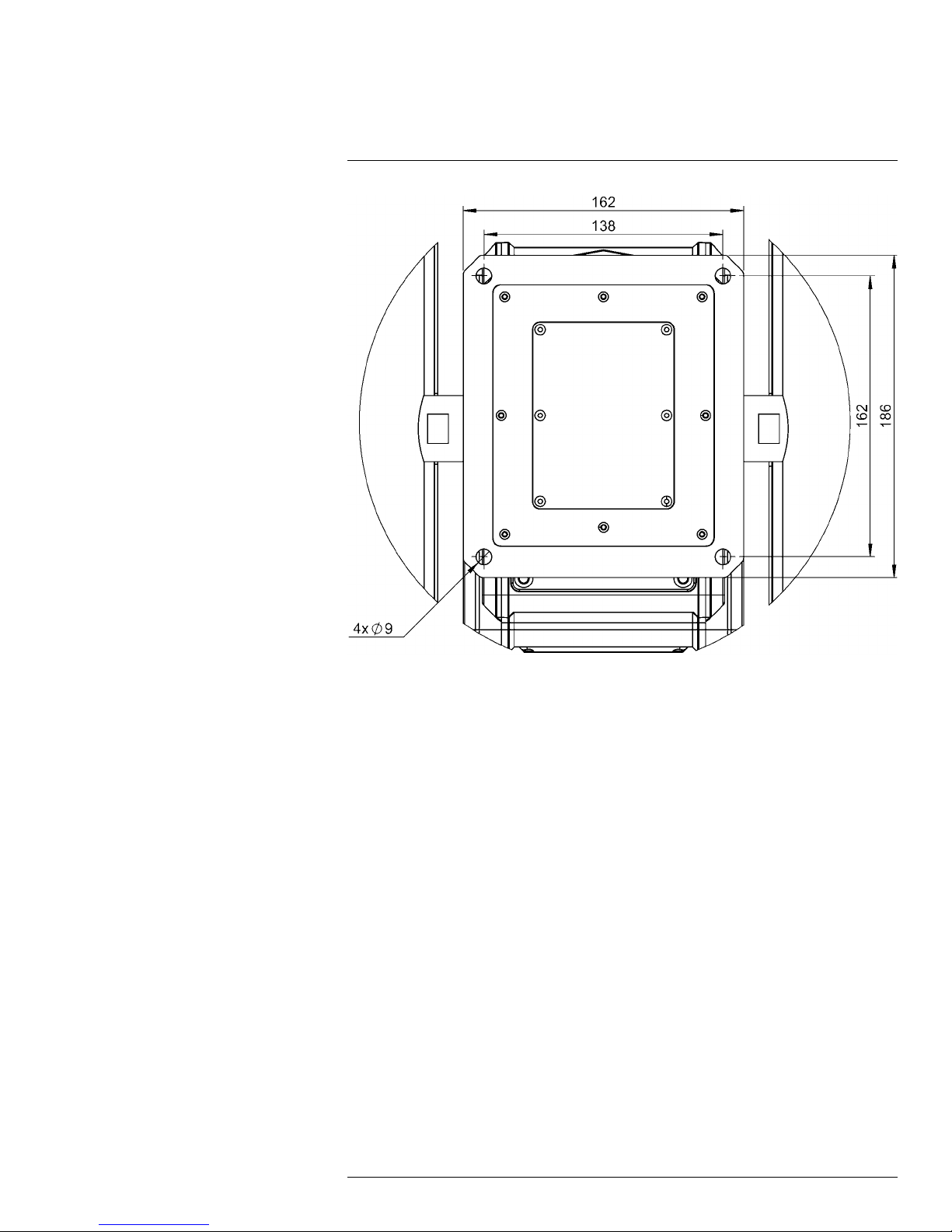
Figure 7.3 FLIR A3xx pt series camera mounting (mm)
Connect and operate the camera as a bench test at ground level prior to mounting the
camera in its final location.
Use a thread-locking compound such as Loctite 242 or an equivalent with all metal-to-metal threaded connections.
Using the template supplied with the camera as a guide, mark the location of the holes for
mounting the camera. If the template is printed, ensure that it is printed to scale so that the
dimensions are correct.
Once the holes are drilled in the mounting surface, install four (4) 5/16″ or M8 bolts
through the base of the camera.
7.5 Prior to cutting/drilling holes
When selecting a mounting location for the FLIR A3xx pt series camera, consider cable
lengths and cable routing. Ensure that the cables are long enough given the proposed
mounting locations and cable routing requirements.
Use cables that have sufficient dimensions to ensure safety (for power cables) and adequate signal strength (for video and communications).
#T559795; r.21371/22369; en-US
12
Page 21

7
Installation
7.6 Back cover
Figure 7.4 Back cover of a FLIR A3xx pt series camera.
1. Shipping plug.
2. Breather valve.
3. Shipping plug.
4. Ground lug, for connection to earth.
5. Mounting screw (×6).
The FLIR A3xx pt series camera comes with two ¾″ NPT cable glands, each with a threehole gland seal insert. Cables can be between 0.23″ and 0.29″ OD. Up to six cables may
be installed. Plugs are required for the insert hole(s) not being used.
Figure 7.5 ¾″ NPTcable gland.
If non-standard cable diameters are used, you may need to locate or fabricate the appropriate insert to fit the desired cable. FLIR Systems does not provide cable gland inserts
other than what is supplied with the system.
Insert the cables through the cable glands on the enclosure before terminating and connecting them. (In general, the terminated connectors will not fit through the cable gland.) If
a terminated cable is required, make a single clean cut in the gland seal to install the cable
into the gland seal.
Proper installation of cable sealing glands and use of appropriate elastomer inserts is critical to long-term reliability. Cables enter the camera mount enclosure through liquid-tight
compression glands. Be sure to insert the cables through the cable glands on the enclosure before terminating and connecting them (the connectors will not fit through the cable
gland). Leave the gland nuts loosened until all cable installation has been completed. Inspect and install gland fittings in the back cover with suitable leak sealant, and tighten to
ensure water-tight fittings. PTFE tape or pipe sealant (e.g., DuPont RectorSeal T) is suitable for this purpose.
#T559795; r.21371/22369; en-US
13
Page 22

7
Installation
7.7 Removing the back cover
Use a cross-head screwdriver to loosen the four captive screws and remove the cover, exposing the connections at the back of the camera. There is a grounding wire connected
between the case and the back cover.
Figure 7.6 Rear view of a FLIR A3xx pt series camera, after the back cover has been released.
1. IP network.
2. Not used.
3. Serial connection for local control.
4. Analog infrared video.
5. Analog video (monitoring output only).
6. Analog visual video.
7. Camera power.
8. Heater power.
NOTE
• Be careful that gaskets are not pinched when mounting the back cover.
• Do not wipe off the grease from the gaskets when mounting the back cover. The grease is critical to
the tightness of the housing.
7.8 Connecting power
Power requirements:
24 VAC (21–30 VAC; 24 VAC: 215 VA max. with heater) or 24 VDC (21–30 VDC; 24 VDC:
195 W max. with heater).
The camera itself does not have an on/off switch. Generally, the FLIR A3xx pt series cam-
era will be connected to a circuit breaker, and the circuit breaker will be used to connect or
interrupt the power supply to the camera. If power is supplied to it, the camera will be in
one of two modes: Booting Up or Powered On.
The power cable supplied by the installer must use wires that are of a sufficient gauge size
(16 AWG is recommended) for the supply voltage and length of the cable run, to ensure
adequate current-carrying capacity. Always follow local building codes.
Ensure the camera is properly grounded. Typical to good grounding practices, the camera
chassis ground should be provided using the lowest resistance path possible. FLIR Systems requires using a grounding strap anchored to the grounding lug on the back plate of
the camera housing and connected to the nearest earth-grounding point.
#T559795; r.21371/22369; en-US
14
Page 23

7
Installation
NOTE
The terminal blocks for power connections will accept a maximum 16 AWG wire size.
7.9 Video connections
The analog video connections on the back of the camera are BNC connectors.
The video cable used should be rated as RG59U or better to ensure a quality video signal.
7.10 Ethernet connection
The cable gland seal is designed for use with shielded Category 6 Ethernet cable.
7.11 Serial communications overview
The installer must first decide if the serial communications settings will be configured via
hardware (DIP switch settings) or software. If the camera has an Ethernet connection, then
generally it will be easier (and more convenient in the long run) to make configuration settings via software. Then, configuration changes can be made over the network without
physically accessing the camera. Also, the settings can be saved to a file, and backed up
or restored as needed.
If the camera is configured via hardware, then configuration changes in the future may require accessing the camera on a tower or pole, dismounting it, removing the back, and so
on. If the camera does not have an Ethernet connection, the DIP switches must be used to
set the serial communication options.
NOTE
• The serial communications parameters for the FLIR A3xx pt series camera are set or modified either
via hardware DIP switch settings or via software, through a web browser interface. A single DIP switch
(SW102-9, software override) determines whether the configuration comes from the hardware DIP
switches or the software settings.
• The DIP switches are only used to control serial communications parameters. Other settings, related
to IP camera functions and so on, must be modified via software (using a web browser).
7.12 Serial connections
For serial communications, it is necessary to set the parameters such as the signalling
standard (RS-232 or RS-422), baud rate, number of stop bits, parity, and so on. It is also
necessary to select the communication protocol used (either Pelco D or Bosch) and the
camera address.
The camera supports RS-422 and RS-232 serial communications using common protocols (Pelco D, Bosch).
NOTE
The terminal blocks for serial connections will accept a maximum 20 AWG wire size.
7.13 Setting configuration dip switches
The figure below shows the locations of dip switches SW102 and SW103
#T559795; r.21371/22369; en-US
15
Page 24

7
Installation
Figure 7.7 Dip switch locations in the FLIR A3xx pt series camera.
Pelco Address: This is the address of the system when configured as a Pelco device. The
available range of values is from decimal 0 to 255.
Table 7.1 Dip switch address/ID settings—SW102
ID Bit 1 Bit 2 Bit 3 Bit 4 Bit 5 Bit 6 Bit 7 Bit 8
0
1
2
3
... ... ... ... ... ... ... ... ...
255
OFF OFF OFF OFF OFF OFF OFF OFF
ON OFF OFF OFF OFF OFF OFF OFF
OFF ON OFF OFF OFF OFF OFF OFF
ON ON OFF OFF OFF OFF OFF OFF
ON ON ON ON ON ON ON ON
Other serial communication parameters: The tables below defines the switch locations, bit
numbering, and on/off settings.
Table 7.2 Dip switch address/ID settings—SW103
Baud rate: This is the baud rate of the system user serial
port. The available values are 2400, 4800, 9600, 19200
kbaud.
Camera control protocol: This is the communication protocol selected for the system when operating over the serial port. The available protocols are Pelco-D and Bosch.
Serial communication protocol: This determines the
electrical interface selected for the user serial port. The
available settings are RS-422 and RS-232.
Settings Descrip-
Bit 1 Bit 2
OFF OFF
ON OFF
OFF ON
ON ON
Bit 3 Bit 4
OFF OFF Pelco-D
ON OFF N/A
OFF ON
ON ON N/A
Bit 5 Bit 6
OFF OFF N/A
ON OFF RS-422
OFF ON RS-232
ON ON N/A
tion
2400
4800
9600
19200
Bosch
#T559795; r.21371/22369; en-US
16
Page 25

7
Installation
Table 7.2 Dip switch address/ID settings—SW103 (continued)
Settings Descrip-
Not used. Bit 7 Bit 8
X X
X X
X X
X X
Software override DIP switch: This setting determines
whether the system will use software settings for configuration or if the dip switch settings will override the software
settings. The default is Off.
Not used. Bit 10
Bit 9
OFF Software
ON Hardware
X
tion
select
select
#T559795; r.21371/22369; en-US
17
Page 26

8
Verifying camera operation
Prior to installing the camera, use a bench test to verify camera operation and to configure
the camera for the local network. The camera provides analog video, and can be controlled through either serial or IP communications providing streaming video over an IP
network.
8.1 Power and analog video
Follow this procedure:
1. Connect the power, video, and serial cables to the camera.
2. Connect the video cable from the camera to a display/monitor, and connect the power
cable to a power supply. The camera operates on 24 VAC (21–30 VAC; 24 VAC: 215
VA max. with heater) or 24 VDC (21–30 VDC; 24 VDC: 195 W max. with heater). Verify
that video is displayed on the monitor.
3. Connect the serial cable from the camera to a serial device such as a keyboard, and
confirm that the camera is responding to serial commands. Before using serial communications, it may be necessary to configure the serial device interface to operate with
the camera. When the camera is turned on, the video temporarily displays system information including the serial number, IP address, Pelco address, Baud rate, and setting of the serial control DIP switch: SW (software control—the default) or HW
(hardware).
• S/N: 1234567
• IP Addr: 192.168.250.116
• PelcoD (Addr:1): 9600 SW
8.2 IP communications
As shipped from the factory, the FLIR A3xx pt series camera has an IP address of
192.168.250.116 with a netmask of 255.255.255.0.
Follow this procedure:
1. Configure a laptop or PC with another IP address from this network (i.e., 192.168.250.
xxx).
2. Connect the camera and the laptop to the same Ethernet switch (or back-to-back with
an Ethernet crossover cable). In some cases, a straight Ethernet cable can be used
because many PCs have auto detect Ethernet interfaces.
#T559795; r.21371/22369; en-US
18
Page 27

8
Verifying camera operation
3. Open a web browser, enter http://192.168.250.116 in the address bar, and press Enter.
If the following screen appears, then you have established IP communications with the
camera.
NOTE
The credentials are the following:
• User name: admin
• Password: fliradmin
8.3 FLIR A3xx pt series camera configuration
Follow this procedure:
1. Open a web browser, enter http://192.168.250.116 in the address bar, and press Enter.
This displays the following screen.
2. Log in using user name: admin and password: fliradmin.
#T559795; r.21371/22369; en-US
19
Page 28

8
Verifying camera operation
3. Under Server, click LAN Settings. This displays the following screen.
4. Under LAN Settings, you can change the following parameters:
• Host name.
• Host name mode.
• IP Address.
• IP Address mode.
• Netmask.
• Gateway.
• MTU.
5. Under Services, click Date and Time. This displays the following screen.
#T559795; r.21371/22369; en-US
20
Page 29

8
Verifying camera operation
6. Under Date and Time, you can change the following parameters:
• Date and Time Settings: NTP (to use a time server) or Custom (to enter a custom
time).
NOTE
If you select NTP, also select Time Zone below. You must also set name servers. See section 8.4
Setting DNS name servers, page 21 for more information.
• Custom Date & Time.
• Time zone.
• Time Server Mode.
• Time Server Address.
8.4 Setting DNS name servers
Follow this procedure:
1. Open a web browser, enter http://192.168.250.116 in the address bar, and press Enter.
This displays the following screen.
2. Log in using user name: admin and password: fliradmin.
#T559795; r.21371/22369; en-US
21
Page 30

8
Verifying camera operation
3. On the top menu bar, click Maintenance. This displays the following screen.
4. Scroll down to DNS servers.
5. Enter at least one name server.
6. Click Save. This displays a screen where you need to accept the name server change.
Click Accept.
#T559795; r.21371/22369; en-US
22
Page 31

8
Verifying camera operation
7. Click Restart Network. This displays a screen where you need to accept typing in the
new URL to reconnect. Click Accept.
#T559795; r.21371/22369; en-US
23
Page 32

9
Technical data
9.1 Online field-of-view calculator
Please visit http://support.flir.com and click the FLIR A3xx pt camera for field-of-view tables for all lens–camera combinations in this camera series.
9.2 Note about technical data
FLIR Systems reserves the right to change specifications at any time without prior notice.
Please check http://support.flir.com for latest changes.
#T559795; r.21371/22369; en-US
24
Page 33

Technical data9
9.3 FLIR A310pt 15° (9 Hz) NTSC
P/N: 60902-1102
Rev.: 22369
General description
The FLIR A310pt Pan & Tilt is an affordable solution for anyone who needs to solve problems that require
built in “smartness” such as analysis and alarm functionality. The FLIR A310pt Pan & Tilt has all the necessary features and functions to build distributed single- or multi-camera solutions to cover large areas to
monitor such as in coal pile monitoring and sub-station monitoring using standard Ethernet hardware and
software protocols.
The FLIR A310pt precision pan/tilt mechanism gives operators accurate pointing control while providing
fully programmable scan patterns, radar slew-to-cue, and slew-to-alarm functionality.
Multi-sensor configurations also include a day/night 36× zoom color CCD camera on the same pan/tilt
package.
Key features:
• Built-in extensive analysis functionality.
• Extensive alarm functionality, as a function of analysis and more.
• H.264, MPEG-4, and MJPEG streaming.
• Built-in web server.
• 100 Mbps Ethernet (100 m cable, wireless, fiber, etc.).
• Composite video output.
• Precise pan/tilt mechanism.
• Daylight camera.
• IP66 rated.
• IP control: FLIR PTseries cameras can be integrated into any existing TCP/IP network and controlled
using a personal computer.
• Serial control interface, use Pelco D or Bosch commands over RS-232, RS-422, or RS-485 to remotely control the FLIR A310 pt.
• Multi-camera software: FLIR Sensors Manager allows users to manage and control a FLIR PT series
camera in a TCP/IP network.
Imaging and optical data
IR resolution 320 × 240 pixels
Thermal sensitivity/NETD < 0.05°C @ +30°C (+86°F) / 50 mK
Field of view (FOV)
Minimum focus distance 1.2 m (3.93 ft.)
Focal length 30.38 mm (1.2 in.)
Spatial resolution (IFOV)
Lens identification Automatic
F-number 1.3
Image frequency 9 Hz
Focus Automatic or manual (built in motor)
Zoom 1–8× continuous, digital, interpolating zooming on
Detector data
Detector type Focal Plane Array (FPA), uncooled microbolometer
Spectral range
Detector pitch 25 µm
Detector time constant Typical 12 ms
15° × 11.25°
0.82 mrad
images
7.5–13 µm
#T559795; r.21371/22369; en-US
25
Page 34

Technical data9
Measurement
Object temperature range
Accuracy ±4°C (±7.2°F) or ±4% of reading
Measurement analysis
Spotmeter
Area 10 boxes with max./min./average/position
Isotherm 1 with above/below/interval
Atmospheric transmission correction Automatic, based on inputs for distance, atmos-
Optics transmission correction Automatic, based on signals from internal sensors
Emissivity correction Variable from 0.01 to 1.0
Reflected apparent temperature correction Automatic, based on input of reflected temperature
External optics/windows correction Automatic, based on input of optics/window trans-
Measurement corrections
• –20 to +120°C (–4 to +248°F)
• 0 to +350°C (+32 to +662°F)
10
pheric temperature and relative humidity
mission and temperature
Global and individual object parameters
Alarm
Alarm functions 6 automatic alarms on any selected measurement
Set-up
Color palettes Color palettes (BW, BW inv, Iron, Rain)
Set-up commands Date/time, Temperature°C/°F
Imaging and optical data (visual camera)
Field of view (FOV) 57.8° (H) to 1.7° (H)
Focal length 3.4 mm (wide) to 122.4 mm (tele)
F-number 1.6 to 4.5
Focus Automatic or manual (built in motor)
Optical Zoom 36× continuous
Electronic Zoom 12× continuous, digital, interpolating
Detector data (visual camera)
Focal Plane Array (FPA) 1/4” Exview HAD CCD
Effective pixels
Technical specification (pan & tilt)
Azimuth Range Az velocity 360° continuous, 0.1 to 60°/sec max
Elevation Range
Programmable presets 128
Automatic heaters
function, camera temperature
380.000
El velocity ± 45°, 0.1 to 30°/sec. max
Clears window from ice. Switched on at +4°C (39°
F). Switched off at +15°C (59°F).
#T559795; r.21371/22369; en-US
26
Page 35

Technical data9
Ethernet
Ethernet Control, result and image
Ethernet, type 100 Mbps
Ethernet, standard IEEE 802.3
Ethernet, connector type RJ-45
Ethernet, communication
Ethernet, video streaming Two independent channels for each camera
- MPEG-4, H.264, or M-JPEG
Ethernet, protocols Ethernet/IP, Modbus TCP, TCP, UDP, SNTP, RTSP,
Composite video
Video out
Video, standard
RTP, HTTP, ICMP, IGMP, ftp, SMTP, SMB (CIFS),
DHCP, MDNS (Bonjour), uPnP
Composite video output, NTSC compatible
CVBS (SMPTE 170M NTSC)
Power system
Power 24 VAC (21-30 VAC; 24 VAC: 215 VA max. with
Environmental data
Operating temperature range –25°C to +50°C (-13°F to +122°F)
Storage temperature range –40°C to +70°C (–40°F to +158°F)
Humidity (operating and storage) IEC 60068-2-30/24 h 95% relative humidity +25°C
EMC
Encapsulation
Bump
Vibration
Physical data
Weight 17.9 kg (39.5 lb.)
Size (L × W × H) 460 × 467 × 326 mm (18.1 × 18.4 × 12.8 in.)
Base mounting
Housing material Aluminum
Shipping information
Packaging, type
List of contents
Packaging, weight
heater) or 24 VDC (21-30 VDC; 24 VDC: 195 W
max. with heater).
to +40°C (+77°F to +104°F)
• EN 61000-6-2 (Immunity)
• EN 61000-6-3 (Emission)
• FCC 47 CFR Part 15 Class B (Emission)
IP 66 (IEC 60529)
5 g, 11 ms (IEC 60068-2-27)
2 g (IEC 60068-2-6)
Cardboard box
• Pan & tilt with infrared camera including lens
and visual camera
• FLIR Sensors Manager download card
• Lens cap
• Printed documentation
• Small accessories kit
• User documentation CD-ROM
#T559795; r.21371/22369; en-US
27
Page 36

Technical data9
Shipping information
Packaging, size 671 × 564 × 464 mm (26.4 × 22.2 × 18.3 in.)
EAN-13 7332558008867
UPC-12
Country of origin Sweden
845188009403
Supplies & accessories:
• T197000; High temp. option +1200°C/+2192°F for FLIR T/B2xx to T/B4xx and A3xx,
A3xxf, A3xxpt, A3xxsc series
• 4119468; ADAPTER PLATE - PT-SERIES
• 223-0017-00; JOYSTICK ASSY, NEXUS CONSOLE
• 500-0461-00; PEDESTAL MOUNT ASSY- PT-SERIES
• 500-0509-00; POLE ADAPTER - PT-SERIES
• 4124857; POWER SUPPLY ASSY, 24VAC - PT-series
• 500-0460-00; WALL MOUNTASSY- PT-SERIES
• 324-0010-00; Hard case - PT-SERIES
• 4130235; FLIR Sensors Manager, pro
#T559795; r.21371/22369; en-US
28
Page 37

Technical data9
9.4 FLIR A310pt 15° (9 Hz) PAL
P/N: 60901-1102
Rev.: 22369
General description
The FLIR A310pt Pan & Tilt is an affordable solution for anyone who needs to solve problems that require
built in “smartness” such as analysis and alarm functionality. The FLIR A310pt Pan & Tilt has all the necessary features and functions to build distributed single- or multi-camera solutions to cover large areas to
monitor such as in coal pile monitoring and sub-station monitoring using standard Ethernet hardware and
software protocols.
The FLIR A310pt precision pan/tilt mechanism gives operators accurate pointing control while providing
fully programmable scan patterns, radar slew-to-cue, and slew-to-alarm functionality.
Multi-sensor configurations also include a day/night 36× zoom color CCD camera on the same pan/tilt
package.
Key features:
• Built-in extensive analysis functionality.
• Extensive alarm functionality, as a function of analysis and more.
• H.264, MPEG-4, and MJPEG streaming.
• Built-in web server.
• 100 Mbps Ethernet (100 m cable, wireless, fiber, etc.).
• Composite video output.
• Precise pan/tilt mechanism.
• Daylight camera.
• IP66 rated.
• IP control: FLIR PTseries cameras can be integrated into any existing TCP/IP network and controlled
using a personal computer.
• Serial control interface, use Pelco D or Bosch commands over RS-232, RS-422, or RS-485 to remotely control the FLIR A310 pt.
• Multi-camera software: FLIR Sensors Manager allows users to manage and control a FLIR PT series
camera in a TCP/IP network.
Imaging and optical data
IR resolution 320 × 240 pixels
Thermal sensitivity/NETD < 0.05°C @ +30°C (+86°F) / 50 mK
Field of view (FOV)
Minimum focus distance 1.2 m (3.93 ft.)
Focal length 30.38 mm (1.2 in.)
Spatial resolution (IFOV)
Lens identification Automatic
F-number 1.3
Image frequency 9 Hz
Focus Automatic or manual (built in motor)
Zoom 1–8× continuous, digital, interpolating zooming on
Detector data
Detector type Focal Plane Array (FPA), uncooled microbolometer
Spectral range
Detector pitch 25 µm
Detector time constant Typical 12 ms
15° × 11.25°
0.82 mrad
images
7.5–13 µm
#T559795; r.21371/22369; en-US
29
Page 38

Technical data9
Measurement
Object temperature range
Accuracy ±4°C (±7.2°F) or ±4% of reading
Measurement analysis
Spotmeter
Area 10 boxes with max./min./average/position
Isotherm 1 with above/below/interval
Atmospheric transmission correction Automatic, based on inputs for distance, atmos-
Optics transmission correction Automatic, based on signals from internal sensors
Emissivity correction Variable from 0.01 to 1.0
Reflected apparent temperature correction Automatic, based on input of reflected temperature
External optics/windows correction Automatic, based on input of optics/window trans-
Measurement corrections
• –20 to +120°C (–4 to +248°F)
• 0 to +350°C (+32 to +662°F)
10
pheric temperature and relative humidity
mission and temperature
Global and individual object parameters
Alarm
Alarm functions 6 automatic alarms on any selected measurement
Set-up
Color palettes Color palettes (BW, BW inv, Iron, Rain)
Set-up commands Date/time, Temperature°C/°F
Imaging and optical data (visual camera)
Field of view (FOV) 57.8° (H) to 1.7° (H)
Focal length 3.4 mm (wide) to 122.4 mm (tele)
F-number 1.6 to 4.5
Focus Automatic or manual (built in motor)
Optical Zoom 36× continuous
Electronic Zoom 12× continuous, digital, interpolating
Detector data (visual camera)
Focal Plane Array (FPA) 1/4” Exview HAD CCD
Effective pixels
Technical specification (pan & tilt)
Azimuth Range Az velocity 360° continuous, 0.1 to 60°/sec max
Elevation Range
Programmable presets 128
Automatic heaters
function, camera temperature
380.000
El velocity ± 45°, 0.1 to 30°/sec. max
Clears window from ice. Switched on at +4°C (39°
F). Switched off at +15°C (59°F).
#T559795; r.21371/22369; en-US
30
Page 39

Technical data9
Ethernet
Ethernet Control, result and image
Ethernet, type 100 Mbps
Ethernet, standard IEEE 802.3
Ethernet, connector type RJ-45
Ethernet, communication
Ethernet, video streaming Two independent channels for each camera
- MPEG-4, H.264, or M-JPEG
Ethernet, protocols Ethernet/IP, Modbus TCP, TCP, UDP, SNTP, RTSP,
Composite video
Video out
Video, standard
RTP, HTTP, ICMP, IGMP, ftp, SMTP, SMB (CIFS),
DHCP, MDNS (Bonjour), uPnP
Composite video output, PAL compatible
CVBS (ITU-R-BT.470 PAL)
Power system
Power 24 VAC (21-30 VAC; 24 VAC: 215 VA max. with
Environmental data
Operating temperature range –25°C to +50°C (-13°F to +122°F)
Storage temperature range –40°C to +70°C (–40°F to +158°F)
Humidity (operating and storage) IEC 60068-2-30/24 h 95% relative humidity +25°C
EMC
Encapsulation
Bump
Vibration
Physical data
Weight 17.9 kg (39.5 lb.)
Size (L × W × H) 460 × 467 × 326 mm (18.1 × 18.4 × 12.8 in.)
Base mounting
Housing material Aluminum
Shipping information
Packaging, type
List of contents
Packaging, weight
heater) or 24 VDC (21-30 VDC; 24 VDC: 195 W
max. with heater).
to +40°C (+77°F to +104°F)
• EN 61000-6-2 (Immunity)
• EN 61000-6-3 (Emission)
• FCC 47 CFR Part 15 Class B (Emission)
IP 66 (IEC 60529)
5 g, 11 ms (IEC 60068-2-27)
2 g (IEC 60068-2-6)
Cardboard box
• Pan & tilt with infrared camera including lens
and visual camera
• FLIR Sensors Manager download card
• Lens cap
• Printed documentation
• Small accessories kit
• User documentation CD-ROM
#T559795; r.21371/22369; en-US
31
Page 40

Technical data9
Shipping information
Packaging, size 671 × 564 × 464 mm (26.4 × 22.2 × 18.3 in.)
EAN-13 7332558008874
UPC-12
Country of origin Sweden
845188009410
Supplies & accessories:
• T197000; High temp. option +1200°C/+2192°F for FLIR T/B2xx to T/B4xx and A3xx,
A3xxf, A3xxpt, A3xxsc series
• 4119468; ADAPTER PLATE - PT-SERIES
• 223-0017-00; JOYSTICK ASSY, NEXUS CONSOLE
• 500-0461-00; PEDESTAL MOUNT ASSY- PT-SERIES
• 500-0509-00; POLE ADAPTER - PT-SERIES
• 4124857; POWER SUPPLY ASSY, 24VAC - PT-series
• 500-0460-00; WALL MOUNTASSY- PT-SERIES
• 324-0010-00; Hard case - PT-SERIES
• 4130235; FLIR Sensors Manager, pro
#T559795; r.21371/22369; en-US
32
Page 41

Technical data9
9.5 FLIR A310pt 15° NTSC
P/N: 61002-1102
Rev.: 22369
General description
The FLIR A310pt Pan & Tilt is an affordable solution for anyone who needs to solve problems that require
built in “smartness” such as analysis and alarm functionality. The FLIR A310pt Pan & Tilt has all the necessary features and functions to build distributed single- or multi-camera solutions to cover large areas to
monitor such as in coal pile monitoring and sub-station monitoring using standard Ethernet hardware and
software protocols.
The FLIR A310pt precision pan/tilt mechanism gives operators accurate pointing control while providing
fully programmable scan patterns, radar slew-to-cue, and slew-to-alarm functionality.
Multi-sensor configurations also include a day/night 36× zoom color CCD camera on the same pan/tilt
package.
Key features:
• Built-in extensive analysis functionality.
• Extensive alarm functionality, as a function of analysis and more.
• H.264, MPEG-4, and MJPEG streaming.
• Built-in web server.
• 100 Mbps Ethernet (100 m cable, wireless, fiber, etc.).
• Composite video output.
• Precise pan/tilt mechanism.
• Daylight camera.
• IP66 rated.
• IP control: FLIR PTseries cameras can be integrated into any existing TCP/IP network and controlled
using a personal computer.
• Serial control interface, use Pelco D or Bosch commands over RS-232, RS-422, or RS-485 to remotely control the FLIR A310 pt.
• Multi-camera software: FLIR Sensors Manager allows users to manage and control a FLIR PT series
camera in a TCP/IP network.
Imaging and optical data
IR resolution 320 × 240 pixels
Thermal sensitivity/NETD < 0.05°C @ +30°C (+86°F) / 50 mK
Field of view (FOV)
Minimum focus distance 1.2 m (3.93 ft.)
Focal length 30.38 mm (1.2 in.)
Spatial resolution (IFOV)
Lens identification Automatic
F-number 1.3
Image frequency 30 Hz
Focus Automatic or manual (built in motor)
Zoom 1–8× continuous, digital, interpolating zooming on
Detector data
Detector type Focal Plane Array (FPA), uncooled microbolometer
Spectral range
Detector pitch 25 µm
Detector time constant Typical 12 ms
15° × 11.25°
0.82 mrad
images
7.5–13 µm
#T559795; r.21371/22369; en-US
33
Page 42

Technical data9
Measurement
Object temperature range
Accuracy ±4°C (±7.2°F) or ±4% of reading
Measurement analysis
Spotmeter
Area 10 boxes with max./min./average/position
Isotherm 1 with above/below/interval
Atmospheric transmission correction Automatic, based on inputs for distance, atmos-
Optics transmission correction Automatic, based on signals from internal sensors
Emissivity correction Variable from 0.01 to 1.0
Reflected apparent temperature correction Automatic, based on input of reflected temperature
External optics/windows correction Automatic, based on input of optics/window trans-
Measurement corrections
• –20 to +120°C (–4 to +248°F)
• 0 to +350°C (+32 to +662°F)
10
pheric temperature and relative humidity
mission and temperature
Global and individual object parameters
Alarm
Alarm functions 6 automatic alarms on any selected measurement
Set-up
Color palettes Color palettes (BW, BW inv, Iron, Rain)
Set-up commands Date/time, Temperature°C/°F
Imaging and optical data (visual camera)
Field of view (FOV) 57.8° (H) to 1.7° (H)
Focal length 3.4 mm (wide) to 122.4 mm (tele)
F-number 1.6 to 4.5
Focus Automatic or manual (built in motor)
Optical Zoom 36× continuous
Electronic Zoom 12× continuous, digital, interpolating
Detector data (visual camera)
Focal Plane Array (FPA) 1/4” Exview HAD CCD
Effective pixels
Technical specification (pan & tilt)
Azimuth Range Az velocity 360° continuous, 0.1 to 60°/sec max
Elevation Range
Programmable presets 128
Automatic heaters
function, camera temperature
380.000
El velocity ± 45°, 0.1 to 30°/sec. max
Clears window from ice. Switched on at +4°C (39°
F). Switched off at +15°C (59°F).
#T559795; r.21371/22369; en-US
34
Page 43

Technical data9
Ethernet
Ethernet Control, result and image
Ethernet, type 100 Mbps
Ethernet, standard IEEE 802.3
Ethernet, connector type RJ-45
Ethernet, communication
Ethernet, video streaming Two independent channels for each camera
- MPEG-4, H.264, or M-JPEG
Ethernet, protocols Ethernet/IP, Modbus TCP, TCP, UDP, SNTP, RTSP,
Composite video
Video out
Video, standard
RTP, HTTP, ICMP, IGMP, ftp, SMTP, SMB (CIFS),
DHCP, MDNS (Bonjour), uPnP
Composite video output, NTSC compatible
CVBS (SMPTE 170M NTSC)
Power system
Power 24 VAC (21-30 VAC; 24 VAC: 215 VA max. with
Environmental data
Operating temperature range –25°C to +50°C (-13°F to +122°F)
Storage temperature range –40°C to +70°C (–40°F to +158°F)
Humidity (operating and storage) IEC 60068-2-30/24 h 95% relative humidity +25°C
EMC
Encapsulation
Bump
Vibration
Physical data
Weight 17.9 kg (39.5 lb.)
Size (L × W × H) 460 × 467 × 326 mm (18.1 × 18.4 × 12.8 in.)
Base mounting
Housing material Aluminum
Shipping information
Packaging, type
List of contents
Packaging, weight
heater) or 24 VDC (21-30 VDC; 24 VDC: 195 W
max. with heater).
to +40°C (+77°F to +104°F)
• EN 61000-6-2 (Immunity)
• EN 61000-6-3 (Emission)
• FCC 47 CFR Part 15 Class B (Emission)
IP 66 (IEC 60529)
5 g, 11 ms (IEC 60068-2-27)
2 g (IEC 60068-2-6)
Cardboard box
• Pan & tilt with infrared camera including lens
and visual camera
• FLIR Sensors Manager download card
• Lens cap
• Printed documentation
• Small accessories kit
• User documentation CD-ROM
#T559795; r.21371/22369; en-US
35
Page 44

Technical data9
Shipping information
Packaging, size 671 × 564 × 464 mm (26.4 × 22.2 × 18.3 in.)
EAN-13 7332558004784
UPC-12
Country of origin Sweden
845188004729
Supplies & accessories:
• T197000; High temp. option +1200°C/+2192°F for FLIR T/B2xx to T/B4xx and A3xx,
A3xxf, A3xxpt, A3xxsc series
• 4119468; ADAPTER PLATE - PT-SERIES
• 223-0017-00; JOYSTICK ASSY, NEXUS CONSOLE
• 500-0461-00; PEDESTAL MOUNT ASSY- PT-SERIES
• 500-0509-00; POLE ADAPTER - PT-SERIES
• 4124857; POWER SUPPLY ASSY, 24VAC - PT-series
• 500-0460-00; WALL MOUNTASSY- PT-SERIES
• 324-0010-00; Hard case - PT-SERIES
• 4130235; FLIR Sensors Manager, pro
#T559795; r.21371/22369; en-US
36
Page 45

Technical data9
9.6 FLIR A310pt 15° PAL
P/N: 61001-1102
Rev.: 22369
General description
The FLIR A310pt Pan & Tilt is an affordable solution for anyone who needs to solve problems that require
built in “smartness” such as analysis and alarm functionality. The FLIR A310pt Pan & Tilt has all the necessary features and functions to build distributed single- or multi-camera solutions to cover large areas to
monitor such as in coal pile monitoring and sub-station monitoring using standard Ethernet hardware and
software protocols.
The FLIR A310pt precision pan/tilt mechanism gives operators accurate pointing control while providing
fully programmable scan patterns, radar slew-to-cue, and slew-to-alarm functionality.
Multi-sensor configurations also include a day/night 36× zoom color CCD camera on the same pan/tilt
package.
Key features:
• Built-in extensive analysis functionality.
• Extensive alarm functionality, as a function of analysis and more.
• H.264, MPEG-4, and MJPEG streaming.
• Built-in web server.
• 100 Mbps Ethernet (100 m cable, wireless, fiber, etc.).
• Composite video output.
• Precise pan/tilt mechanism.
• Daylight camera.
• IP66 rated.
• IP control: FLIR PTseries cameras can be integrated into any existing TCP/IP network and controlled
using a personal computer.
• Serial control interface, use Pelco D or Bosch commands over RS-232, RS-422, or RS-485 to remotely control the FLIR A310 pt.
• Multi-camera software: FLIR Sensors Manager allows users to manage and control a FLIR PT series
camera in a TCP/IP network.
Imaging and optical data
IR resolution 320 × 240 pixels
Thermal sensitivity/NETD < 0.05°C @ +30°C (+86°F) / 50 mK
Field of view (FOV)
Minimum focus distance 1.2 m (3.93 ft.)
Focal length 30.38 mm (1.2 in.)
Spatial resolution (IFOV)
Lens identification Automatic
F-number 1.3
Image frequency 30 Hz
Focus Automatic or manual (built in motor)
Zoom 1–8× continuous, digital, interpolating zooming on
Detector data
Detector type Focal Plane Array (FPA), uncooled microbolometer
Spectral range
Detector pitch 25 µm
Detector time constant Typical 12 ms
15° × 11.25°
0.82 mrad
images
7.5–13 µm
#T559795; r.21371/22369; en-US
37
Page 46

Technical data9
Measurement
Object temperature range
Accuracy ±4°C (±7.2°F) or ±4% of reading
Measurement analysis
Spotmeter
Area 10 boxes with max./min./average/position
Isotherm 1 with above/below/interval
Atmospheric transmission correction Automatic, based on inputs for distance, atmos-
Optics transmission correction Automatic, based on signals from internal sensors
Emissivity correction Variable from 0.01 to 1.0
Reflected apparent temperature correction Automatic, based on input of reflected temperature
External optics/windows correction Automatic, based on input of optics/window trans-
Measurement corrections
• –20 to +120°C (–4 to +248°F)
• 0 to +350°C (+32 to +662°F)
10
pheric temperature and relative humidity
mission and temperature
Global and individual object parameters
Alarm
Alarm functions 6 automatic alarms on any selected measurement
Set-up
Color palettes Color palettes (BW, BW inv, Iron, Rain)
Set-up commands Date/time, Temperature°C/°F
Imaging and optical data (visual camera)
Field of view (FOV) 57.8° (H) to 1.7° (H)
Focal length 3.4 mm (wide) to 122.4 mm (tele)
F-number 1.6 to 4.5
Focus Automatic or manual (built in motor)
Optical Zoom 36× continuous
Electronic Zoom 12× continuous, digital, interpolating
Detector data (visual camera)
Focal Plane Array (FPA) 1/4” Exview HAD CCD
Effective pixels
Technical specification (pan & tilt)
Azimuth Range Az velocity 360° continuous, 0.1 to 60°/sec max
Elevation Range
Programmable presets 128
Automatic heaters
function, camera temperature
380.000
El velocity ± 45°, 0.1 to 30°/sec. max
Clears window from ice. Switched on at +4°C (39°
F). Switched off at +15°C (59°F).
#T559795; r.21371/22369; en-US
38
Page 47

Technical data9
Ethernet
Ethernet Control, result and image
Ethernet, type 100 Mbps
Ethernet, standard IEEE 802.3
Ethernet, connector type RJ-45
Ethernet, communication
Ethernet, video streaming Two independent channels for each camera
- MPEG-4, H.264, or M-JPEG
Ethernet, protocols Ethernet/IP, Modbus TCP, TCP, UDP, SNTP, RTSP,
Composite video
Video out
Video, standard
RTP, HTTP, ICMP, IGMP, ftp, SMTP, SMB (CIFS),
DHCP, MDNS (Bonjour), uPnP
Composite video output, PAL compatible
CVBS (ITU-R-BT.470 PAL)
Power system
Power 24 VAC (21-30 VAC; 24 VAC: 215 VA max. with
Environmental data
Operating temperature range –25°C to +50°C (-13°F to +122°F)
Storage temperature range –40°C to +70°C (–40°F to +158°F)
Humidity (operating and storage) IEC 60068-2-30/24 h 95% relative humidity +25°C
EMC
Encapsulation
Bump
Vibration
Physical data
Weight 17.9 kg (39.5 lb.)
Size (L × W × H) 460 × 467 × 326 mm (18.1 × 18.4 × 12.8 in.)
Base mounting
Housing material Aluminum
Shipping information
Packaging, type
List of contents
Packaging, weight
heater) or 24 VDC (21-30 VDC; 24 VDC: 195 W
max. with heater).
to +40°C (+77°F to +104°F)
• EN 61000-6-2 (Immunity)
• EN 61000-6-3 (Emission)
• FCC 47 CFR Part 15 Class B (Emission)
IP 66 (IEC 60529)
5 g, 11 ms (IEC 60068-2-27)
2 g (IEC 60068-2-6)
Cardboard box
• Pan & tilt with infrared camera including lens
and visual camera
• FLIR Sensors Manager download card
• Lens cap
• Printed documentation
• Small accessories kit
• User documentation CD-ROM
#T559795; r.21371/22369; en-US
39
Page 48

Technical data9
Shipping information
Packaging, size 671 × 564 × 464 mm (26.4 × 22.2 × 18.3 in.)
EAN-13 7332558008881
UPC-12
Country of origin Sweden
845188009427
Supplies & accessories:
• T197000; High temp. option +1200°C/+2192°F for FLIR T/B2xx to T/B4xx and A3xx,
A3xxf, A3xxpt, A3xxsc series
• 4119468; ADAPTER PLATE - PT-SERIES
• 223-0017-00; JOYSTICK ASSY, NEXUS CONSOLE
• 500-0461-00; PEDESTAL MOUNT ASSY- PT-SERIES
• 500-0509-00; POLE ADAPTER - PT-SERIES
• 4124857; POWER SUPPLY ASSY, 24VAC - PT-series
• 500-0460-00; WALL MOUNTASSY- PT-SERIES
• 324-0010-00; Hard case - PT-SERIES
• 4130235; FLIR Sensors Manager, pro
#T559795; r.21371/22369; en-US
40
Page 49

Technical data9
9.7 FLIR A310pt 25° (9 Hz) NTSC
P/N: 60902-1103
Rev.: 22369
General description
The FLIR A310pt Pan & Tilt is an affordable solution for anyone who needs to solve problems that require
built in “smartness” such as analysis and alarm functionality. The FLIR A310pt Pan & Tilt has all the necessary features and functions to build distributed single- or multi-camera solutions to cover large areas to
monitor such as in coal pile monitoring and sub-station monitoring using standard Ethernet hardware and
software protocols.
The FLIR A310pt precision pan/tilt mechanism gives operators accurate pointing control while providing
fully programmable scan patterns, radar slew-to-cue, and slew-to-alarm functionality.
Multi-sensor configurations also include a day/night 36× zoom color CCD camera on the same pan/tilt
package.
Key features:
• Built-in extensive analysis functionality.
• Extensive alarm functionality, as a function of analysis and more.
• H.264, MPEG-4, and MJPEG streaming.
• Built-in web server.
• 100 Mbps Ethernet (100 m cable, wireless, fiber, etc.).
• Composite video output.
• Precise pan/tilt mechanism.
• Daylight camera.
• IP66 rated.
• IP control: FLIR PTseries cameras can be integrated into any existing TCP/IP network and controlled
using a personal computer.
• Serial control interface, use Pelco D or Bosch commands over RS-232, RS-422, or RS-485 to remotely control the FLIR A310 pt.
• Multi-camera software: FLIR Sensors Manager allows users to manage and control a FLIR PT series
camera in a TCP/IP network.
Imaging and optical data
IR resolution 320 × 240 pixels
Thermal sensitivity/NETD < 0.05°C @ +30°C (+86°F) / 50 mK
Field of view (FOV)
Minimum focus distance 0.4 m (1.31 ft.)
Focal length 18 mm (0.7 in.)
Spatial resolution (IFOV)
Lens identification Automatic
F-number 1.3
Image frequency 9 Hz
Focus Automatic or manual (built in motor)
Zoom 1–8× continuous, digital, interpolating zooming on
Detector data
Detector type Focal Plane Array (FPA), uncooled microbolometer
Spectral range
Detector pitch 25 µm
Detector time constant Typical 12 ms
25° × 18.8°
1.36 mrad
images
7.5–13 µm
#T559795; r.21371/22369; en-US
41
Page 50

Technical data9
Measurement
Object temperature range
Accuracy ±4°C (±7.2°F) or ±4% of reading
Measurement analysis
Spotmeter
Area 10 boxes with max./min./average/position
Isotherm 1 with above/below/interval
Atmospheric transmission correction Automatic, based on inputs for distance, atmos-
Optics transmission correction Automatic, based on signals from internal sensors
Emissivity correction Variable from 0.01 to 1.0
Reflected apparent temperature correction Automatic, based on input of reflected temperature
External optics/windows correction Automatic, based on input of optics/window trans-
Measurement corrections
• –20 to +120°C (–4 to +248°F)
• 0 to +350°C (+32 to +662°F)
10
pheric temperature and relative humidity
mission and temperature
Global and individual object parameters
Alarm
Alarm functions 6 automatic alarms on any selected measurement
Set-up
Color palettes Color palettes (BW, BW inv, Iron, Rain)
Set-up commands Date/time, Temperature°C/°F
Imaging and optical data (visual camera)
Field of view (FOV) 57.8° (H) to 1.7° (H)
Focal length 3.4 mm (wide) to 122.4 mm (tele)
F-number 1.6 to 4.5
Focus Automatic or manual (built in motor)
Optical Zoom 36× continuous
Electronic Zoom 12× continuous, digital, interpolating
Detector data (visual camera)
Focal Plane Array (FPA) 1/4” Exview HAD CCD
Effective pixels
Technical specification (pan & tilt)
Azimuth Range Az velocity 360° continuous, 0.1 to 60°/sec max
Elevation Range
Programmable presets 128
Automatic heaters
function, camera temperature
380.000
El velocity ± 45°, 0.1 to 30°/sec. max
Clears window from ice. Switched on at +4°C (39°
F). Switched off at +15°C (59°F).
#T559795; r.21371/22369; en-US
42
Page 51

Technical data9
Ethernet
Ethernet Control, result and image
Ethernet, type 100 Mbps
Ethernet, standard IEEE 802.3
Ethernet, connector type RJ-45
Ethernet, communication
Ethernet, video streaming Two independent channels for each camera
- MPEG-4, H.264, or M-JPEG
Ethernet, protocols Ethernet/IP, Modbus TCP, TCP, UDP, SNTP, RTSP,
Composite video
Video out
Video, standard
RTP, HTTP, ICMP, IGMP, ftp, SMTP, SMB (CIFS),
DHCP, MDNS (Bonjour), uPnP
Composite video output, NTSC compatible
CVBS (SMPTE 170M NTSC)
Power system
Power 24 VAC (21-30 VAC; 24 VAC: 215 VA max. with
Environmental data
Operating temperature range –25°C to +50°C (-13°F to +122°F)
Storage temperature range –40°C to +70°C (–40°F to +158°F)
Humidity (operating and storage) IEC 60068-2-30/24 h 95% relative humidity +25°C
EMC
Encapsulation
Bump
Vibration
Physical data
Weight 17.8 kg (39.3 lb.)
Size (L × W × H) 460 × 467 × 326 mm (18.1 × 18.4 × 12.8 in.)
Base mounting
Housing material Aluminum
Shipping information
Packaging, type
List of contents
Packaging, weight
heater) or 24 VDC (21-30 VDC; 24 VDC: 195 W
max. with heater).
to +40°C (+77°F to +104°F)
• EN 61000-6-2 (Immunity)
• EN 61000-6-3 (Emission)
• FCC 47 CFR Part 15 Class B (Emission)
IP 66 (IEC 60529)
5 g, 11 ms (IEC 60068-2-27)
2 g (IEC 60068-2-6)
Cardboard box
• Pan & tilt with infrared camera including lens
and visual camera
• FLIR Sensors Manager download card
• Lens cap
• Printed documentation
• Small accessories kit
• User documentation CD-ROM
#T559795; r.21371/22369; en-US
43
Page 52

Technical data9
Shipping information
Packaging, size 671 × 564 × 464 mm (26.4 × 22.2 × 18.3 in.)
EAN-13 7332558008898
UPC-12
Country of origin Sweden
845188009434
Supplies & accessories:
• T197000; High temp. option +1200°C/+2192°F for FLIR T/B2xx to T/B4xx and A3xx,
A3xxf, A3xxpt, A3xxsc series
• 4119468; ADAPTER PLATE - PT-SERIES
• 223-0017-00; JOYSTICK ASSY, NEXUS CONSOLE
• 500-0461-00; PEDESTAL MOUNT ASSY- PT-SERIES
• 500-0509-00; POLE ADAPTER - PT-SERIES
• 4124857; POWER SUPPLY ASSY, 24VAC - PT-series
• 500-0460-00; WALL MOUNTASSY- PT-SERIES
• 324-0010-00; Hard case - PT-SERIES
• 4130235; FLIR Sensors Manager, pro
#T559795; r.21371/22369; en-US
44
Page 53

Technical data9
9.8 FLIR A310pt 25° (9 Hz) PAL
P/N: 60901-1103
Rev.: 22369
General description
The FLIR A310pt Pan & Tilt is an affordable solution for anyone who needs to solve problems that require
built in “smartness” such as analysis and alarm functionality. The FLIR A310pt Pan & Tilt has all the necessary features and functions to build distributed single- or multi-camera solutions to cover large areas to
monitor such as in coal pile monitoring and sub-station monitoring using standard Ethernet hardware and
software protocols.
The FLIR A310pt precision pan/tilt mechanism gives operators accurate pointing control while providing
fully programmable scan patterns, radar slew-to-cue, and slew-to-alarm functionality.
Multi-sensor configurations also include a day/night 36× zoom color CCD camera on the same pan/tilt
package.
Key features:
• Built-in extensive analysis functionality.
• Extensive alarm functionality, as a function of analysis and more.
• H.264, MPEG-4, and MJPEG streaming.
• Built-in web server.
• 100 Mbps Ethernet (100 m cable, wireless, fiber, etc.).
• Composite video output.
• Precise pan/tilt mechanism.
• Daylight camera.
• IP66 rated.
• IP control: FLIR PTseries cameras can be integrated into any existing TCP/IP network and controlled
using a personal computer.
• Serial control interface, use Pelco D or Bosch commands over RS-232, RS-422, or RS-485 to remotely control the FLIR A310 pt.
• Multi-camera software: FLIR Sensors Manager allows users to manage and control a FLIR PT series
camera in a TCP/IP network.
Imaging and optical data
IR resolution 320 × 240 pixels
Thermal sensitivity/NETD < 0.05°C @ +30°C (+86°F) / 50 mK
Field of view (FOV)
Minimum focus distance 0.4 m (1.31 ft.)
Focal length 18 mm (0.7 in.)
Spatial resolution (IFOV)
Lens identification Automatic
F-number 1.3
Image frequency 9 Hz
Focus Automatic or manual (built in motor)
Zoom 1–8× continuous, digital, interpolating zooming on
Detector data
Detector type Focal Plane Array (FPA), uncooled microbolometer
Spectral range
Detector pitch 25 µm
Detector time constant Typical 12 ms
25° × 18.8°
1.36 mrad
images
7.5–13 µm
#T559795; r.21371/22369; en-US
45
Page 54

Technical data9
Measurement
Object temperature range
Accuracy ±4°C (±7.2°F) or ±4% of reading
Measurement analysis
Spotmeter
Area 10 boxes with max./min./average/position
Isotherm 1 with above/below/interval
Atmospheric transmission correction Automatic, based on inputs for distance, atmos-
Optics transmission correction Automatic, based on signals from internal sensors
Emissivity correction Variable from 0.01 to 1.0
Reflected apparent temperature correction Automatic, based on input of reflected temperature
External optics/windows correction Automatic, based on input of optics/window trans-
Measurement corrections
• –20 to +120°C (–4 to +248°F)
• 0 to +350°C (+32 to +662°F)
10
pheric temperature and relative humidity
mission and temperature
Global and individual object parameters
Alarm
Alarm functions 6 automatic alarms on any selected measurement
Set-up
Color palettes Color palettes (BW, BW inv, Iron, Rain)
Set-up commands Date/time, Temperature°C/°F
Imaging and optical data (visual camera)
Field of view (FOV) 57.8° (H) to 1.7° (H)
Focal length 3.4 mm (wide) to 122.4 mm (tele)
F-number 1.6 to 4.5
Focus Automatic or manual (built in motor)
Optical Zoom 36× continuous
Electronic Zoom 12× continuous, digital, interpolating
Detector data (visual camera)
Focal Plane Array (FPA) 1/4” Exview HAD CCD
Effective pixels
Technical specification (pan & tilt)
Azimuth Range Az velocity 360° continuous, 0.1 to 60°/sec max
Elevation Range
Programmable presets 128
Automatic heaters
function, camera temperature
380.000
El velocity ± 45°, 0.1 to 30°/sec. max
Clears window from ice. Switched on at +4°C (39°
F). Switched off at +15°C (59°F).
#T559795; r.21371/22369; en-US
46
Page 55

Technical data9
Ethernet
Ethernet Control, result and image
Ethernet, type 100 Mbps
Ethernet, standard IEEE 802.3
Ethernet, connector type RJ-45
Ethernet, communication
Ethernet, video streaming Two independent channels for each camera
- MPEG-4, H.264, or M-JPEG
Ethernet, protocols Ethernet/IP, Modbus TCP, TCP, UDP, SNTP, RTSP,
Composite video
Video out
Video, standard
RTP, HTTP, ICMP, IGMP, ftp, SMTP, SMB (CIFS),
DHCP, MDNS (Bonjour), uPnP
Composite video output, PAL compatible
CVBS (ITU-R-BT.470 PAL)
Power system
Power 24 VAC (21-30 VAC; 24 VAC: 215 VA max. with
Environmental data
Operating temperature range –25°C to +50°C (-13°F to +122°F)
Storage temperature range –40°C to +70°C (–40°F to +158°F)
Humidity (operating and storage) IEC 60068-2-30/24 h 95% relative humidity +25°C
EMC
Encapsulation
Bump
Vibration
Physical data
Weight 17.8 kg (39.3 lb.)
Size (L × W × H) 460 × 467 × 326 mm (18.1 × 18.4 × 12.8 in.)
Base mounting
Housing material Aluminum
Shipping information
Packaging, type
List of contents
Packaging, weight
heater) or 24 VDC (21-30 VDC; 24 VDC: 195 W
max. with heater).
to +40°C (+77°F to +104°F)
• EN 61000-6-2 (Immunity)
• EN 61000-6-3 (Emission)
• FCC 47 CFR Part 15 Class B (Emission)
IP 66 (IEC 60529)
5 g, 11 ms (IEC 60068-2-27)
2 g (IEC 60068-2-6)
Cardboard box
• Pan & tilt with infrared camera including lens
and visual camera
• FLIR Sensors Manager download card
• Lens cap
• Printed documentation
• Small accessories kit
• User documentation CD-ROM
#T559795; r.21371/22369; en-US
47
Page 56

Technical data9
Shipping information
Packaging, size 671 × 564 × 464 mm (26.4 × 22.2 × 18.3 in.)
EAN-13 7332558007891
UPC-12
Country of origin Sweden
845188008260
Supplies & accessories:
• T197000; High temp. option +1200°C/+2192°F for FLIR T/B2xx to T/B4xx and A3xx,
A3xxf, A3xxpt, A3xxsc series
• 4119468; ADAPTER PLATE - PT-SERIES
• 223-0017-00; JOYSTICK ASSY, NEXUS CONSOLE
• 500-0461-00; PEDESTAL MOUNT ASSY- PT-SERIES
• 500-0509-00; POLE ADAPTER - PT-SERIES
• 4124857; POWER SUPPLY ASSY, 24VAC - PT-series
• 500-0460-00; WALL MOUNTASSY- PT-SERIES
• 324-0010-00; Hard case - PT-SERIES
• 4130235; FLIR Sensors Manager, pro
#T559795; r.21371/22369; en-US
48
Page 57

Technical data9
9.9 FLIR A310pt 25° NTSC
P/N: 61002-1103
Rev.: 22369
General description
The FLIR A310pt Pan & Tilt is an affordable solution for anyone who needs to solve problems that require
built in “smartness” such as analysis and alarm functionality. The FLIR A310pt Pan & Tilt has all the necessary features and functions to build distributed single- or multi-camera solutions to cover large areas to
monitor such as in coal pile monitoring and sub-station monitoring using standard Ethernet hardware and
software protocols.
The FLIR A310pt precision pan/tilt mechanism gives operators accurate pointing control while providing
fully programmable scan patterns, radar slew-to-cue, and slew-to-alarm functionality.
Multi-sensor configurations also include a day/night 36× zoom color CCD camera on the same pan/tilt
package.
Key features:
• Built-in extensive analysis functionality.
• Extensive alarm functionality, as a function of analysis and more.
• H.264, MPEG-4, and MJPEG streaming.
• Built-in web server.
• 100 Mbps Ethernet (100 m cable, wireless, fiber, etc.).
• Composite video output.
• Precise pan/tilt mechanism.
• Daylight camera.
• IP66 rated.
• IP control: FLIR PTseries cameras can be integrated into any existing TCP/IP network and controlled
using a personal computer.
• Serial control interface, use Pelco D or Bosch commands over RS-232, RS-422, or RS-485 to remotely control the FLIR A310 pt.
• Multi-camera software: FLIR Sensors Manager allows users to manage and control a FLIR PT series
camera in a TCP/IP network.
Imaging and optical data
IR resolution 320 × 240 pixels
Thermal sensitivity/NETD < 0.05°C @ +30°C (+86°F) / 50 mK
Field of view (FOV)
Minimum focus distance 0.4 m (1.31 ft.)
Focal length 18 mm (0.7 in.)
Spatial resolution (IFOV)
Lens identification Automatic
F-number 1.3
Image frequency 30 Hz
Focus Automatic or manual (built in motor)
Zoom 1–8× continuous, digital, interpolating zooming on
Detector data
Detector type Focal Plane Array (FPA), uncooled microbolometer
Spectral range
Detector pitch 25 µm
Detector time constant Typical 12 ms
25° × 18.8°
1.36 mrad
images
7.5–13 µm
#T559795; r.21371/22369; en-US
49
Page 58

Technical data9
Measurement
Object temperature range
Accuracy ±4°C (±7.2°F) or ±4% of reading
Measurement analysis
Spotmeter
Area 10 boxes with max./min./average/position
Isotherm 1 with above/below/interval
Atmospheric transmission correction Automatic, based on inputs for distance, atmos-
Optics transmission correction Automatic, based on signals from internal sensors
Emissivity correction Variable from 0.01 to 1.0
Reflected apparent temperature correction Automatic, based on input of reflected temperature
External optics/windows correction Automatic, based on input of optics/window trans-
Measurement corrections
• –20 to +120°C (–4 to +248°F)
• 0 to +350°C (+32 to +662°F)
10
pheric temperature and relative humidity
mission and temperature
Global and individual object parameters
Alarm
Alarm functions 6 automatic alarms on any selected measurement
Set-up
Color palettes Color palettes (BW, BW inv, Iron, Rain)
Set-up commands Date/time, Temperature°C/°F
Imaging and optical data (visual camera)
Field of view (FOV) 57.8° (H) to 1.7° (H)
Focal length 3.4 mm (wide) to 122.4 mm (tele)
F-number 1.6 to 4.5
Focus Automatic or manual (built in motor)
Optical Zoom 36× continuous
Electronic Zoom 12× continuous, digital, interpolating
Detector data (visual camera)
Focal Plane Array (FPA) 1/4” Exview HAD CCD
Effective pixels
Technical specification (pan & tilt)
Azimuth Range Az velocity 360° continuous, 0.1 to 60°/sec max
Elevation Range
Programmable presets 128
Automatic heaters
function, camera temperature
380.000
El velocity +/- 45°, 0.1 to 30°/sec. max
Clears window from ice. Switched on at +4°C (39°
F). Switched off at +15°C (59°F).
#T559795; r.21371/22369; en-US
50
Page 59

Technical data9
Ethernet
Ethernet Control, result and image
Ethernet, type 100 Mbps
Ethernet, standard IEEE 802.3
Ethernet, connector type RJ-45
Ethernet, communication
Ethernet, video streaming Two independent channels for each camera
- MPEG-4, H.264, or M-JPEG
Ethernet, protocols Ethernet/IP, Modbus TCP, TCP, UDP, SNTP, RTSP,
Composite video
Video out
Video, standard
RTP, HTTP, ICMP, IGMP, ftp, SMTP, SMB (CIFS),
DHCP, MDNS (Bonjour), uPnP
Composite video output, NTSC compatible
CVBS (SMPTE 170M NTSC)
Power system
Power 24 VAC (21-30 VAC; 24 VAC: 215 VA max. with
Environmental data
Operating temperature range –25°C to +50°C (-13°F to +122°F)
Storage temperature range –40°C to +70°C (–40°F to +158°F)
Humidity (operating and storage) IEC 60068-2-30/24 h 95% relative humidity +25°C
EMC
Encapsulation
Bump
Vibration
Physical data
Weight 17.8 kg (39.3 lb.)
Size (L × W × H) 460 × 467 × 326 mm (18.1 × 18.4 × 12.8 in.)
Base mounting
Housing material Aluminum
Shipping information
Packaging, type
List of contents
Packaging, weight
heater) or 24 VDC (21-30 VDC; 24 VDC: 195 W
max. with heater).
to +40°C (+77°F to +104°F)
• EN 61000-6-2 (Immunity)
• EN 61000-6-3 (Emission)
• FCC 47 CFR Part 15 Class B (Emission)
IP 66 (IEC 60529)
5 g, 11 ms (IEC 60068-2-27)
2 g (IEC 60068-2-6)
Cardboard box
• Pan & tilt with infrared camera including lens
and visual camera
• FLIR Sensors Manager download card
• Lens cap
• Printed documentation
• Small accessories kit
• User documentation CD-ROM
#T559795; r.21371/22369; en-US
51
Page 60

Technical data9
Shipping information
Packaging, size 671 × 564 × 464 mm (26.4 × 22.2 × 18.3 in.)
EAN-13 7332558005910
UPC-12
Country of origin Sweden
845188006105
Supplies & accessories:
• T197000; High temp. option +1200°C/+2192°F for FLIR T/B2xx to T/B4xx and A3xx,
A3xxf, A3xxpt, A3xxsc series
• 4119468; ADAPTER PLATE - PT-SERIES
• 223-0017-00; JOYSTICK ASSY, NEXUS CONSOLE
• 500-0461-00; PEDESTAL MOUNT ASSY- PT-SERIES
• 500-0509-00; POLE ADAPTER - PT-SERIES
• 4124857; POWER SUPPLY ASSY, 24VAC - PT-series
• 500-0460-00; WALL MOUNTASSY- PT-SERIES
• 324-0010-00; Hard case - PT-SERIES
• 4130235; FLIR Sensors Manager, pro
#T559795; r.21371/22369; en-US
52
Page 61

Technical data9
9.10 FLIR A310pt 25° PAL
P/N: 61001-1103
Rev.: 22369
General description
The FLIR A310pt Pan & Tilt is an affordable solution for anyone who needs to solve problems that require
built in “smartness” such as analysis and alarm functionality. The FLIR A310pt Pan & Tilt has all the necessary features and functions to build distributed single- or multi-camera solutions to cover large areas to
monitor such as in coal pile monitoring and sub-station monitoring using standard Ethernet hardware and
software protocols.
The FLIR A310pt precision pan/tilt mechanism gives operators accurate pointing control while providing
fully programmable scan patterns, radar slew-to-cue, and slew-to-alarm functionality.
Multi-sensor configurations also include a day/night 36× zoom color CCD camera on the same pan/tilt
package.
Key features:
• Built-in extensive analysis functionality.
• Extensive alarm functionality, as a function of analysis and more.
• H.264, MPEG-4, and MJPEG streaming.
• Built-in web server.
• 100 Mbps Ethernet (100 m cable, wireless, fiber, etc.).
• Composite video output.
• Precise pan/tilt mechanism.
• Daylight camera.
• IP66 rated.
• IP control: FLIR PTseries cameras can be integrated into any existing TCP/IP network and controlled
using a personal computer.
• Serial control interface, use Pelco D or Bosch commands over RS-232, RS-422, or RS-485 to remotely control the FLIR A310 pt.
• Multi-camera software: FLIR Sensors Manager allows users to manage and control a FLIR PT series
camera in a TCP/IP network.
Imaging and optical data
IR resolution 320 × 240 pixels
Thermal sensitivity/NETD < 0.05°C @ +30°C (+86°F) / 50 mK
Field of view (FOV)
Minimum focus distance 0.4 m (1.31 ft.)
Focal length 18 mm (0.7 in.)
Spatial resolution (IFOV)
Lens identification Automatic
F-number 1.3
Image frequency 30 Hz
Focus Automatic or manual (built in motor)
Zoom 1–8× continuous, digital, interpolating zooming on
Detector data
Detector type Focal Plane Array (FPA), uncooled microbolometer
Spectral range
Detector pitch 25 µm
Detector time constant Typical 12 ms
25° × 18.8°
1.36 mrad
images
7.5–13 µm
#T559795; r.21371/22369; en-US
53
Page 62

Technical data9
Measurement
Object temperature range
Accuracy ±4°C (±7.2°F) or ±4% of reading
Measurement analysis
Spotmeter
Area 10 boxes with max./min./average/position
Isotherm 1 with above/below/interval
Atmospheric transmission correction Automatic, based on inputs for distance, atmos-
Optics transmission correction Automatic, based on signals from internal sensors
Emissivity correction Variable from 0.01 to 1.0
Reflected apparent temperature correction Automatic, based on input of reflected temperature
External optics/windows correction Automatic, based on input of optics/window trans-
Measurement corrections
• –20 to +120°C (–4 to +248°F)
• 0 to +350°C (+32 to +662°F)
10
pheric temperature and relative humidity
mission and temperature
Global and individual object parameters
Alarm
Alarm functions 6 automatic alarms on any selected measurement
Set-up
Color palettes Color palettes (BW, BW inv, Iron, Rain)
Set-up commands Date/time, Temperature°C/°F
Imaging and optical data (visual camera)
Field of view (FOV) 57.8° (H) to 1.7° (H)
Focal length 3.4 mm (wide) to 122.4 mm (tele)
F-number 1.6 to 4.5
Focus Automatic or manual (built in motor)
Optical Zoom 36× continuous
Electronic Zoom 12× continuous, digital, interpolating
Detector data (visual camera)
Focal Plane Array (FPA) 1/4” Exview HAD CCD
Effective pixels
Technical specification (pan & tilt)
Azimuth Range Az velocity 360° continuous, 0.1 to 60°/sec max
Elevation Range
Programmable presets 128
Automatic heaters
function, camera temperature
380.000
El velocity ± 45°, 0.1 to 30°/sec. max
Clears window from ice. Switched on at +4°C (39°
F). Switched off at +15°C (59°F).
#T559795; r.21371/22369; en-US
54
Page 63

Technical data9
Ethernet
Ethernet Control, result and image
Ethernet, type 100 Mbps
Ethernet, standard IEEE 802.3
Ethernet, connector type RJ-45
Ethernet, communication
Ethernet, video streaming Two independent channels for each camera
- MPEG-4, H.264, or M-JPEG
Ethernet, protocols Ethernet/IP, Modbus TCP, TCP, UDP, SNTP, RTSP,
Composite video
Video out
Video, standard
RTP, HTTP, ICMP, IGMP, ftp, SMTP, SMB (CIFS),
DHCP, MDNS (Bonjour), uPnP
Composite video output, PAL compatible
CVBS (ITU-R-BT.470 PAL)
Power system
Power 24 VAC (21-30 VAC; 24 VAC: 215 VA max. with
Environmental data
Operating temperature range –25°C to +50°C (-13°F to +122°F)
Storage temperature range –40°C to +70°C (–40°F to +158°F)
Humidity (operating and storage) IEC 60068-2-30/24 h 95% relative humidity +25°C
EMC
Encapsulation
Bump
Vibration
Physical data
Weight 17.8 kg (39.3 lb.)
Size (L × W × H) 460 × 467 × 326 mm (18.1 × 18.4 × 12.8 in.)
Base mounting
Housing material Aluminum
Shipping information
Packaging, type
List of contents
Packaging, weight
heater) or 24 VDC (21-30 VDC; 24 VDC: 195 W
max. with heater).
to +40°C (+77°F to +104°F)
• EN 61000-6-2 (Immunity)
• EN 61000-6-3 (Emission)
• FCC 47 CFR Part 15 Class B (Emission)
IP 66 (IEC 60529)
5 g, 11 ms (IEC 60068-2-27)
2 g (IEC 60068-2-6)
Cardboard box
• Pan & tilt with infrared camera including lens
and visual camera
• FLIR Sensors Manager download card
• Lens cap
• Printed documentation
• Small accessories kit
• User documentation CD-ROM
#T559795; r.21371/22369; en-US
55
Page 64

Technical data9
Shipping information
Packaging, size 671 × 564 × 464 mm (26.4 × 22.2 × 18.3 in.)
EAN-13 7332558008904
UPC-12
Country of origin Sweden
845188009441
Supplies & accessories:
• T197000; High temp. option +1200°C/+2192°F for FLIR T/B2xx to T/B4xx and A3xx,
A3xxf, A3xxpt, A3xxsc series
• 4119468; ADAPTER PLATE - PT-SERIES
• 223-0017-00; JOYSTICK ASSY, NEXUS CONSOLE
• 500-0461-00; PEDESTAL MOUNT ASSY- PT-SERIES
• 500-0509-00; POLE ADAPTER - PT-SERIES
• 4124857; POWER SUPPLY ASSY, 24VAC - PT-series
• 500-0460-00; WALL MOUNTASSY- PT-SERIES
• 324-0010-00; Hard case - PT-SERIES
• 4130235; FLIR Sensors Manager, pro
#T559795; r.21371/22369; en-US
56
Page 65

Technical data9
9.11 FLIR A310pt 45° (9 Hz) NTSC
P/N: 60902-1104
Rev.: 22369
General description
The FLIR A310pt Pan & Tilt is an affordable solution for anyone who needs to solve problems that require
built in “smartness” such as analysis and alarm functionality. The FLIR A310pt Pan & Tilt has all the necessary features and functions to build distributed single- or multi-camera solutions to cover large areas to
monitor such as in coal pile monitoring and sub-station monitoring using standard Ethernet hardware and
software protocols.
The FLIR A310pt precision pan/tilt mechanism gives operators accurate pointing control while providing
fully programmable scan patterns, radar slew-to-cue, and slew-to-alarm functionality.
Multi-sensor configurations also include a day/night 36× zoom color CCD camera on the same pan/tilt
package.
Key features:
• Built-in extensive analysis functionality.
• Extensive alarm functionality, as a function of analysis and more.
• H.264, MPEG-4, and MJPEG streaming.
• Built-in web server.
• 100 Mbps Ethernet (100 m cable, wireless, fiber, etc.).
• Composite video output.
• Precise pan/tilt mechanism.
• Daylight camera.
• IP66 rated.
• IP control: FLIR PTseries cameras can be integrated into any existing TCP/IP network and controlled
using a personal computer.
• Serial control interface, use Pelco D or Bosch commands over RS-232, RS-422, or RS-485 to remotely control the FLIR A310 pt.
• Multi-camera software: FLIR Sensors Manager allows users to manage and control a FLIR PT series
camera in a TCP/IP network.
Imaging and optical data
IR resolution 320 × 240 pixels
Thermal sensitivity/NETD < 0.05°C @ +30°C (+86°F) / 50 mK
Field of view (FOV)
Minimum focus distance 0.20 m (0.66 ft.)
Focal length 9.66 mm (0.38 in.)
Spatial resolution (IFOV)
Lens identification Automatic
F-number 1.3
Image frequency 9 Hz
Focus Automatic or manual (built in motor)
Zoom 1–8× continuous, digital, interpolating zooming on
Detector data
Detector type Focal Plane Array (FPA), uncooled microbolometer
Spectral range
Detector pitch 25 µm
Detector time constant Typical 12 ms
45° × 33.8°
2.59 mrad
images
7.5–13 µm
#T559795; r.21371/22369; en-US
57
Page 66

Technical data9
Measurement
Object temperature range
Accuracy ±4°C (±7.2°F) or ±4% of reading
Measurement analysis
Spotmeter
Area 10 boxes with max./min./average/position
Isotherm 1 with above/below/interval
Atmospheric transmission correction Automatic, based on inputs for distance, atmos-
Optics transmission correction Automatic, based on signals from internal sensors
Emissivity correction Variable from 0.01 to 1.0
Reflected apparent temperature correction Automatic, based on input of reflected temperature
External optics/windows correction Automatic, based on input of optics/window trans-
Measurement corrections
• –20 to +120°C (–4 to +248°F)
• 0 to +350°C (+32 to +662°F)
10
pheric temperature and relative humidity
mission and temperature
Global and individual object parameters
Alarm
Alarm functions 6 automatic alarms on any selected measurement
Set-up
Color palettes Color palettes (BW, BW inv, Iron, Rain)
Set-up commands Date/time, Temperature°C/°F
Imaging and optical data (visual camera)
Field of view (FOV) 57.8° (H) to 1.7° (H)
Focal length 3.4 mm (wide) to 122.4 mm (tele)
F-number 1.6 to 4.5
Focus Automatic or manual (built in motor)
Optical Zoom 36× continuous
Electronic Zoom 12× continuous, digital, interpolating
Detector data (visual camera)
Focal Plane Array (FPA) 1/4” Exview HAD CCD
Effective pixels
Technical specification (pan & tilt)
Azimuth Range Az velocity 360° continuous, 0.1 to 60°/sec max
Elevation Range
Programmable presets 128
Automatic heaters
function, camera temperature
380.000
El velocity ± 45°, 0.1 to 30°/sec. max
Clears window from ice. Switched on at +4°C (39°
F). Switched off at +15°C (59°F).
#T559795; r.21371/22369; en-US
58
Page 67

Technical data9
Ethernet
Ethernet Control, result and image
Ethernet, type 100 Mbps
Ethernet, standard IEEE 802.3
Ethernet, connector type RJ-45
Ethernet, communication
Ethernet, video streaming Two independent channels for each camera
- MPEG-4, H.264, or M-JPEG
Ethernet, protocols Ethernet/IP, Modbus TCP, TCP, UDP, SNTP, RTSP,
Composite video
Video out
Video, standard
RTP, HTTP, ICMP, IGMP, ftp, SMTP, SMB (CIFS),
DHCP, MDNS (Bonjour), uPnP
Composite video output, NTSC compatible
CVBS (SMPTE 170M NTSC)
Power system
Power 24 VAC (21-30 VAC; 24 VAC: 215 VA max. with
Environmental data
Operating temperature range –25°C to +50°C (-13°F to +122°F)
Storage temperature range –40°C to +70°C (–40°F to +158°F)
Humidity (operating and storage) IEC 60068-2-30/24 h 95% relative humidity +25°C
EMC
Encapsulation
Bump
Vibration
Physical data
Weight 17.9 kg (39.5 lb.)
Size (L × W × H) 460 × 467 × 326 mm (18.1 × 18.4 × 12.8 in.)
Base mounting
Housing material Aluminum
Shipping information
Packaging, type
List of contents
Packaging, weight
heater) or 24 VDC (21-30 VDC; 24 VDC: 195 W
max. with heater).
to +40°C (+77°F to +104°F)
• EN 61000-6-2 (Immunity)
• EN 61000-6-3 (Emission)
• FCC 47 CFR Part 15 Class B (Emission)
IP 66 (IEC 60529)
5 g, 11 ms (IEC 60068-2-27)
2 g (IEC 60068-2-6)
Cardboard box
• Pan & tilt with infrared camera including lens
and visual camera
• FLIR Sensors Manager download card
• Lens cap
• Printed documentation
• Small accessories kit
• User documentation CD-ROM
#T559795; r.21371/22369; en-US
59
Page 68

Technical data9
Shipping information
Packaging, size 671 × 564 × 464 mm (26.4 × 22.2 × 18.3 in.)
EAN-13 7332558008911
UPC-12
Country of origin Sweden
845188009458
Supplies & accessories:
• T197000; High temp. option +1200°C/+2192°F for FLIR T/B2xx to T/B4xx and A3xx,
A3xxf, A3xxpt, A3xxsc series
• 4119468; ADAPTER PLATE - PT-SERIES
• 223-0017-00; JOYSTICK ASSY, NEXUS CONSOLE
• 500-0461-00; PEDESTAL MOUNT ASSY- PT-SERIES
• 500-0509-00; POLE ADAPTER - PT-SERIES
• 4124857; POWER SUPPLY ASSY, 24VAC - PT-series
• 500-0460-00; WALL MOUNTASSY- PT-SERIES
• 324-0010-00; Hard case - PT-SERIES
• 4130235; FLIR Sensors Manager, pro
#T559795; r.21371/22369; en-US
60
Page 69

Technical data9
9.12 FLIR A310pt 45° (9 Hz) PAL
P/N: 60901-1104
Rev.: 22369
General description
The FLIR A310pt Pan & Tilt is an affordable solution for anyone who needs to solve problems that require
built in “smartness” such as analysis and alarm functionality. The FLIR A310pt Pan & Tilt has all the necessary features and functions to build distributed single- or multi-camera solutions to cover large areas to
monitor such as in coal pile monitoring and sub-station monitoring using standard Ethernet hardware and
software protocols.
The FLIR A310pt precision pan/tilt mechanism gives operators accurate pointing control while providing
fully programmable scan patterns, radar slew-to-cue, and slew-to-alarm functionality.
Multi-sensor configurations also include a day/night 36× zoom color CCD camera on the same pan/tilt
package.
Key features:
• Built-in extensive analysis functionality.
• Extensive alarm functionality, as a function of analysis and more.
• H.264, MPEG-4, and MJPEG streaming.
• Built-in web server.
• 100 Mbps Ethernet (100 m cable, wireless, fiber, etc.).
• Composite video output.
• Precise pan/tilt mechanism.
• Daylight camera.
• IP66 rated.
• IP control: FLIR PTseries cameras can be integrated into any existing TCP/IP network and controlled
using a personal computer.
• Serial control interface, use Pelco D or Bosch commands over RS-232, RS-422, or RS-485 to remotely control the FLIR A310 pt.
• Multi-camera software: FLIR Sensors Manager allows users to manage and control a FLIR PT series
camera in a TCP/IP network.
Imaging and optical data
IR resolution 320 × 240 pixels
Thermal sensitivity/NETD < 0.05°C @ +30°C (+86°F) / 50 mK
Field of view (FOV)
Minimum focus distance 0.20 m (0.66 ft.)
Focal length 9.66 mm (0.38 in.)
Spatial resolution (IFOV)
Lens identification Automatic
F-number 1.3
Image frequency 9 Hz
Focus Automatic or manual (built in motor)
Zoom 1–8× continuous, digital, interpolating zooming on
Detector data
Detector type Focal Plane Array (FPA), uncooled microbolometer
Spectral range
Detector pitch 25 µm
Detector time constant Typical 12 ms
45° × 33.8°
2.59 mrad
images
7.5–13 µm
#T559795; r.21371/22369; en-US
61
Page 70

Technical data9
Measurement
Object temperature range
Accuracy ±4°C (±7.2°F) or ±4% of reading
Measurement analysis
Spotmeter
Area 10 boxes with max./min./average/position
Isotherm 1 with above/below/interval
Atmospheric transmission correction Automatic, based on inputs for distance, atmos-
Optics transmission correction Automatic, based on signals from internal sensors
Emissivity correction Variable from 0.01 to 1.0
Reflected apparent temperature correction Automatic, based on input of reflected temperature
External optics/windows correction Automatic, based on input of optics/window trans-
Measurement corrections
• –20 to +120°C (–4 to +248°F)
• 0 to +350°C (+32 to +662°F)
10
pheric temperature and relative humidity
mission and temperature
Global and individual object parameters
Alarm
Alarm functions 6 automatic alarms on any selected measurement
Set-up
Color palettes Color palettes (BW, BW inv, Iron, Rain)
Set-up commands Date/time, Temperature°C/°F
Imaging and optical data (visual camera)
Field of view (FOV) 57.8° (H) to 1.7° (H)
Focal length 3.4 mm (wide) to 122.4 mm (tele)
F-number 1.6 to 4.5
Focus Automatic or manual (built in motor)
Optical Zoom 36× continuous
Electronic Zoom 12× continuous, digital, interpolating
Detector data (visual camera)
Focal Plane Array (FPA) 1/4” Exview HAD CCD
Effective pixels
Technical specification (pan & tilt)
Azimuth Range Az velocity 360° continuous, 0.1 to 60°/sec max
Elevation Range
Programmable presets 128
Automatic heaters
function, camera temperature
380.000
El velocity ± 45°, 0.1 to 30°/sec. max
Clears window from ice. Switched on at +4°C (39°
F). Switched off at +15°C (59°F).
#T559795; r.21371/22369; en-US
62
Page 71

Technical data9
Ethernet
Ethernet Control, result and image
Ethernet, type 100 Mbps
Ethernet, standard IEEE 802.3
Ethernet, connector type RJ-45
Ethernet, communication
Ethernet, video streaming Two independent channels for each camera
- MPEG-4, H.264, or M-JPEG
Ethernet, protocols Ethernet/IP, Modbus TCP, TCP, UDP, SNTP, RTSP,
Composite video
Video out
Video, standard
RTP, HTTP, ICMP, IGMP, ftp, SMTP, SMB (CIFS),
DHCP, MDNS (Bonjour), uPnP
Composite video output, PAL compatible
CVBS (ITU-R-BT.470 PAL)
Power system
Power 24 VAC (21-30 VAC; 24 VAC: 215 VA max. with
Environmental data
Operating temperature range –25°C to +50°C (-13°F to +122°F)
Storage temperature range –40°C to +70°C (–40°F to +158°F)
Humidity (operating and storage) IEC 60068-2-30/24 h 95% relative humidity +25°C
EMC
Encapsulation
Bump
Vibration
Physical data
Weight 17.9 kg (39.5 lb.)
Size (L × W × H) 460 × 467 × 326 mm (18.1 × 18.4 × 12.8 in.)
Base mounting
Housing material Aluminum
Shipping information
Packaging, type
List of contents
Packaging, weight
heater) or 24 VDC (21-30 VDC; 24 VDC: 195 W
max. with heater).
to +40°C (+77°F to +104°F)
• EN 61000-6-2 (Immunity)
• EN 61000-6-3 (Emission)
• FCC 47 CFR Part 15 Class B (Emission)
IP 66 (IEC 60529)
5 g, 11 ms (IEC 60068-2-27)
2 g (IEC 60068-2-6)
Cardboard box
• Pan & tilt with infrared camera including lens
and visual camera
• FLIR Sensors Manager download card
• Lens cap
• Printed documentation
• Small accessories kit
• User documentation CD-ROM
#T559795; r.21371/22369; en-US
63
Page 72

Technical data9
Shipping information
Packaging, size 671 × 564 × 464 mm (26.4 × 22.2 × 18.3 in.)
EAN-13 7332558008928
UPC-12
Country of origin Sweden
845188009465
Supplies & accessories:
• T197000; High temp. option +1200°C/+2192°F for FLIR T/B2xx to T/B4xx and A3xx,
A3xxf, A3xxpt, A3xxsc series
• 4119468; ADAPTER PLATE - PT-SERIES
• 223-0017-00; JOYSTICK ASSY, NEXUS CONSOLE
• 500-0461-00; PEDESTAL MOUNT ASSY- PT-SERIES
• 500-0509-00; POLE ADAPTER - PT-SERIES
• 4124857; POWER SUPPLY ASSY, 24VAC - PT-series
• 500-0460-00; WALL MOUNTASSY- PT-SERIES
• 324-0010-00; Hard case - PT-SERIES
• 4130235; FLIR Sensors Manager, pro
#T559795; r.21371/22369; en-US
64
Page 73

Technical data9
9.13 FLIR A310pt 45° NTSC
P/N: 61002-1104
Rev.: 22369
General description
The FLIR A310pt Pan & Tilt is an affordable solution for anyone who needs to solve problems that require
built in “smartness” such as analysis and alarm functionality. The FLIR A310pt Pan & Tilt has all the necessary features and functions to build distributed single- or multi-camera solutions to cover large areas to
monitor such as in coal pile monitoring and sub-station monitoring using standard Ethernet hardware and
software protocols.
The FLIR A310pt precision pan/tilt mechanism gives operators accurate pointing control while providing
fully programmable scan patterns, radar slew-to-cue, and slew-to-alarm functionality.
Multi-sensor configurations also include a day/night 36× zoom color CCD camera on the same pan/tilt
package.
Key features:
• Built-in extensive analysis functionality.
• Extensive alarm functionality, as a function of analysis and more.
• H.264, MPEG-4, and MJPEG streaming.
• Built-in web server.
• 100 Mbps Ethernet (100 m cable, wireless, fiber, etc.).
• Composite video output.
• Precise pan/tilt mechanism.
• Daylight camera.
• IP66 rated.
• IP control: FLIR PTseries cameras can be integrated into any existing TCP/IP network and controlled
using a personal computer.
• Serial control interface, use Pelco D or Bosch commands over RS-232, RS-422, or RS-485 to remotely control the FLIR A310 pt.
• Multi-camera software: FLIR Sensors Manager allows users to manage and control a FLIR PT series
camera in a TCP/IP network.
Imaging and optical data
IR resolution 320 × 240 pixels
Thermal sensitivity/NETD < 0.05°C @ +30°C (+86°F) / 50 mK
Field of view (FOV)
Minimum focus distance 0.20 m (0.66 ft.)
Focal length 9.66 mm (0.38 in.)
Spatial resolution (IFOV)
Lens identification Automatic
F-number 1.3
Image frequency 30 Hz
Focus Automatic or manual (built in motor)
Zoom 1–8× continuous, digital, interpolating zooming on
Detector data
Detector type Focal Plane Array (FPA), uncooled microbolometer
Spectral range
Detector pitch 25 µm
Detector time constant Typical 12 ms
45° × 33.8°
2.59 mrad
images
7.5–13 µm
#T559795; r.21371/22369; en-US
65
Page 74

Technical data9
Measurement
Object temperature range
Accuracy ±4°C (±7.2°F) or ±4% of reading
Measurement analysis
Spotmeter
Area 10 boxes with max./min./average/position
Isotherm 1 with above/below/interval
Atmospheric transmission correction Automatic, based on inputs for distance, atmos-
Optics transmission correction Automatic, based on signals from internal sensors
Emissivity correction Variable from 0.01 to 1.0
Reflected apparent temperature correction Automatic, based on input of reflected temperature
External optics/windows correction Automatic, based on input of optics/window trans-
Measurement corrections
• –20 to +120°C (–4 to +248°F)
• 0 to +350°C (+32 to +662°F)
10
pheric temperature and relative humidity
mission and temperature
Global and individual object parameters
Alarm
Alarm functions 6 automatic alarms on any selected measurement
Set-up
Color palettes Color palettes (BW, BW inv, Iron, Rain)
Set-up commands Date/time, Temperature°C/°F
Imaging and optical data (visual camera)
Field of view (FOV) 57.8° (H) to 1.7° (H)
Focal length 3.4 mm (wide) to 122.4 mm (tele)
F-number 1.6 to 4.5
Focus Automatic or manual (built in motor)
Optical Zoom 36× continuous
Electronic Zoom 12× continuous, digital, interpolating
Detector data (visual camera)
Focal Plane Array (FPA) 1/4” Exview HAD CCD
Effective pixels
Technical specification (pan & tilt)
Azimuth Range Az velocity 360° continuous, 0.1 to 60°/sec max
Elevation Range
Programmable presets 128
Automatic heaters
function, camera temperature
380.000
El velocity ± 45°, 0.1 to 30°/sec. max
Clears window from ice. Switched on at +4°C (39°
F). Switched off at +15°C (59°F).
#T559795; r.21371/22369; en-US
66
Page 75

Technical data9
Ethernet
Ethernet Control, result and image
Ethernet, type 100 Mbps
Ethernet, standard IEEE 802.3
Ethernet, connector type RJ-45
Ethernet, communication
Ethernet, video streaming Two independent channels for each camera
- MPEG-4, H.264, or M-JPEG
Ethernet, protocols Ethernet/IP, Modbus TCP, TCP, UDP, SNTP, RTSP,
Composite video
Video out
Video, standard
RTP, HTTP, ICMP, IGMP, ftp, SMTP, SMB (CIFS),
DHCP, MDNS (Bonjour), uPnP
Composite video output, NTSC compatible
CVBS (SMPTE 170M NTSC)
Power system
Power 24 VAC (21-30 VAC; 24 VAC: 215 VA max. with
Environmental data
Operating temperature range –25°C to +50°C (-13°F to +122°F)
Storage temperature range –40°C to +70°C (–40°F to +158°F)
Humidity (operating and storage) IEC 60068-2-30/24 h 95% relative humidity +25°C
EMC
Encapsulation
Bump
Vibration
Physical data
Weight 17.9 kg (39.5 lb.)
Size (L × W × H) 460 × 467 × 326 mm (18.1 × 18.4 × 12.8 in.)
Base mounting
Housing material Aluminum
Shipping information
Packaging, type
List of contents
Packaging, weight
heater) or 24 VDC (21-30 VDC; 24 VDC: 195 W
max. with heater).
to +40°C (+77°F to +104°F)
• EN 61000-6-2 (Immunity)
• EN 61000-6-3 (Emission)
• FCC 47 CFR Part 15 Class B (Emission)
IP 66 (IEC 60529)
5 g, 11 ms (IEC 60068-2-27)
2 g (IEC 60068-2-6)
Cardboard box
• Pan & tilt with infrared camera including lens
and visual camera
• FLIR Sensors Manager download card
• Lens cap
• Printed documentation
• Small accessories kit
• User documentation CD-ROM
#T559795; r.21371/22369; en-US
67
Page 76

Technical data9
Shipping information
Packaging, size 671 × 564 × 464 mm (26.4 × 22.2 × 18.3 in.)
EAN-13 7332558008935
UPC-12
Country of origin Sweden
845188009472
Supplies & accessories:
• T197000; High temp. option +1200°C/+2192°F for FLIR T/B2xx to T/B4xx and A3xx,
A3xxf, A3xxpt, A3xxsc series
• 4119468; ADAPTER PLATE - PT-SERIES
• 223-0017-00; JOYSTICK ASSY, NEXUS CONSOLE
• 500-0461-00; PEDESTAL MOUNT ASSY- PT-SERIES
• 500-0509-00; POLE ADAPTER - PT-SERIES
• 4124857; POWER SUPPLY ASSY, 24VAC - PT-series
• 500-0460-00; WALL MOUNTASSY- PT-SERIES
• 324-0010-00; Hard case - PT-SERIES
• 4130235; FLIR Sensors Manager, pro
#T559795; r.21371/22369; en-US
68
Page 77

Technical data9
9.14 FLIR A310pt 45° PAL
P/N: 61001-1104
Rev.: 22369
General description
The FLIR A310pt Pan & Tilt is an affordable solution for anyone who needs to solve problems that require
built in “smartness” such as analysis and alarm functionality. The FLIR A310pt Pan & Tilt has all the necessary features and functions to build distributed single- or multi-camera solutions to cover large areas to
monitor such as in coal pile monitoring and sub-station monitoring using standard Ethernet hardware and
software protocols.
The FLIR A310pt precision pan/tilt mechanism gives operators accurate pointing control while providing
fully programmable scan patterns, radar slew-to-cue, and slew-to-alarm functionality.
Multi-sensor configurations also include a day/night 36× zoom color CCD camera on the same pan/tilt
package.
Key features:
• Built-in extensive analysis functionality.
• Extensive alarm functionality, as a function of analysis and more.
• H.264, MPEG-4, and MJPEG streaming.
• Built-in web server.
• 100 Mbps Ethernet (100 m cable, wireless, fiber, etc.).
• Composite video output.
• Precise pan/tilt mechanism.
• Daylight camera.
• IP66 rated.
• IP control: FLIR PTseries cameras can be integrated into any existing TCP/IP network and controlled
using a personal computer.
• Serial control interface, use Pelco D or Bosch commands over RS-232, RS-422, or RS-485 to remotely control the FLIR A310 pt.
• Multi-camera software: FLIR Sensors Manager allows users to manage and control a FLIR PT series
camera in a TCP/IP network.
Imaging and optical data
IR resolution 320 × 240 pixels
Thermal sensitivity/NETD < 0.05°C @ +30°C (+86°F) / 50 mK
Field of view (FOV)
Minimum focus distance 0.20 m (0.66 ft.)
Focal length 9.66 mm (0.38 in.)
Spatial resolution (IFOV)
Lens identification Automatic
F-number 1.3
Image frequency 30 Hz
Focus Automatic or manual (built in motor)
Zoom 1–8× continuous, digital, interpolating zooming on
Detector data
Detector type Focal Plane Array (FPA), uncooled microbolometer
Spectral range
Detector pitch 25 µm
Detector time constant Typical 12 ms
45° × 33.8°
2.59 mrad
images
7.5–13 µm
#T559795; r.21371/22369; en-US
69
Page 78

Technical data9
Measurement
Object temperature range
Accuracy ±4°C (±7.2°F) or ±4% of reading
Measurement analysis
Spotmeter
Area 10 boxes with max./min./average/position
Isotherm 1 with above/below/interval
Atmospheric transmission correction Automatic, based on inputs for distance, atmos-
Optics transmission correction Automatic, based on signals from internal sensors
Emissivity correction Variable from 0.01 to 1.0
Reflected apparent temperature correction Automatic, based on input of reflected temperature
External optics/windows correction Automatic, based on input of optics/window trans-
Measurement corrections
• –20 to +120°C (–4 to +248°F)
• 0 to +350°C (+32 to +662°F)
10
pheric temperature and relative humidity
mission and temperature
Global and individual object parameters
Alarm
Alarm functions 6 automatic alarms on any selected measurement
Set-up
Color palettes Color palettes (BW, BW inv, Iron, Rain)
Set-up commands Date/time, Temperature°C/°F
Imaging and optical data (visual camera)
Field of view (FOV) 57.8° (H) to 1.7° (H)
Focal length 3.4 mm (wide) to 122.4 mm (tele)
F-number 1.6 to 4.5
Focus Automatic or manual (built in motor)
Optical Zoom 36× continuous
Electronic Zoom 12× continuous, digital, interpolating
Detector data (visual camera)
Focal Plane Array (FPA) 1/4” Exview HAD CCD
Effective pixels
Technical specification (pan & tilt)
Azimuth Range Az velocity 360° continuous, 0.1 to 60°/sec max
Elevation Range
Programmable presets 128
Automatic heaters
function, camera temperature
380.000
El velocity ± 45°, 0.1 to 30°/sec. max
Clears window from ice. Switched on at +4°C (39°
F). Switched off at +15°C (59°F).
#T559795; r.21371/22369; en-US
70
Page 79

Technical data9
Ethernet
Ethernet Control, result and image
Ethernet, type 100 Mbps
Ethernet, standard IEEE 802.3
Ethernet, connector type RJ-45
Ethernet, communication
Ethernet, video streaming Two independent channels for each camera
- MPEG-4, H.264, or M-JPEG
Ethernet, protocols Ethernet/IP, Modbus TCP, TCP, UDP, SNTP, RTSP,
Composite video
Video out
Video, standard
RTP, HTTP, ICMP, IGMP, ftp, SMTP, SMB (CIFS),
DHCP, MDNS (Bonjour), uPnP
Composite video output, PAL compatible
CVBS (ITU-R-BT.470 PAL)
Power system
Power 24 VAC (21-30 VAC; 24 VAC: 215 VA max. with
Environmental data
Operating temperature range –25°C to +50°C (-13°F to +122°F)
Storage temperature range –40°C to +70°C (–40°F to +158°F)
Humidity (operating and storage) IEC 60068-2-30/24 h 95% relative humidity +25°C
EMC
Encapsulation
Bump
Vibration
Physical data
Weight 17.9 kg (39.5 lb.)
Size (L × W × H) 460 × 467 × 326 mm (18.1 × 18.4 × 12.8 in.)
Base mounting
Housing material Aluminum
heater) or 24 VDC (21-30 VDC; 24 VDC: 195 W
max. with heater).
to +40°C (+77°F to +104°F)
• EN 61000-6-2 (Immunity)
• EN 61000-6-3 (Emission)
• FCC 47 CFR Part 15 Class B (Emission)
IP 66 (IEC 60529)
5 g, 11 ms (IEC 60068-2-27)
2 g (IEC 60068-2-6)
#T559795; r.21371/22369; en-US
71
Page 80

Technical data9
Shipping information
Packaging, type
List of contents
Packaging, weight
Packaging, size 671 × 564 × 464 mm (26.4 × 22.2 × 18.3 in.)
EAN-13 7332558008942
UPC-12
Country of origin Sweden
Cardboard box
• Pan & tilt with infrared camera including lens
and visual camera
• Calibration certificate
• Downloads brochure
• FLIR Sensors Manager CD-ROM
• Lens cap
• Printed Getting Started Guide
• Printed Important Information Guide
• Service & training brochure
• Small accessories kit
• User documentation CD-ROM
• Registration card
845188009489
Supplies & accessories:
• T197000; High temp. option +1200°C/+2192°F for FLIR T/B2xx to T/B4xx and A3xx,
A3xxf, A3xxpt, A3xxsc series
• 4119468; ADAPTER PLATE - PT-SERIES
• 223-0017-00; JOYSTICK ASSY, NEXUS CONSOLE
• 500-0461-00; PEDESTAL MOUNT ASSY- PT-SERIES
• 500-0509-00; POLE ADAPTER - PT-SERIES
• 4124857; POWER SUPPLY ASSY, 24VAC - PT-series
• 500-0460-00; WALL MOUNTASSY- PT-SERIES
• 324-0010-00; Hard case - PT-SERIES
• 4130235; FLIR Sensors Manager, pro
#T559795; r.21371/22369; en-US
72
Page 81

Technical data9
9.15 FLIR A310pt 6° (9 Hz) NTSC
P/N: 60902-1101
Rev.: 22369
General description
The FLIR A310pt Pan & Tilt is an affordable solution for anyone who needs to solve problems that require
built in “smartness” such as analysis and alarm functionality. The FLIR A310pt Pan & Tilt has all the necessary features and functions to build distributed single- or multi-camera solutions to cover large areas to
monitor such as in coal pile monitoring and sub-station monitoring using standard Ethernet hardware and
software protocols.
The FLIR A310pt precision pan/tilt mechanism gives operators accurate pointing control while providing
fully programmable scan patterns, radar slew-to-cue, and slew-to-alarm functionality.
Multi-sensor configurations also include a day/night 36× zoom color CCD camera on the same pan/tilt
package.
Key features:
• Built-in extensive analysis functionality.
• Extensive alarm functionality, as a function of analysis and more.
• H.264, MPEG-4, and MJPEG streaming.
• Built-in web server.
• 100 Mbps Ethernet (100 m cable, wireless, fiber, etc.).
• Composite video output.
• Precise pan/tilt mechanism.
• Daylight camera.
• IP66 rated.
• IP control: FLIR PTseries cameras can be integrated into any existing TCP/IP network and controlled
using a personal computer.
• Serial control interface, use Pelco D or Bosch commands over RS-232, RS-422, or RS-485 to remotely control the FLIR A310 pt.
• Multi-camera software: FLIR Sensors Manager allows users to manage and control a FLIR PT series
camera in a TCP/IP network.
Imaging and optical data
IR resolution 320 × 240 pixels
Thermal sensitivity/NETD < 0.05°C @ +30°C (+86°F) / 50 mK
Field of view (FOV)
Minimum focus distance 4 m (13.11 ft.)
Focal length 76 mm (3.0 in.)
Spatial resolution (IFOV)
Lens identification Automatic
F-number 1.3
Image frequency 9 Hz
Focus Automatic or manual (built in motor)
Zoom 1–8× continuous, digital, interpolating zooming on
Detector data
Detector type Focal Plane Array (FPA), uncooled microbolometer
Spectral range
Detector pitch 25 µm
Detector time constant Typical 12 ms
6° × 4.5°
0.33 mrad
images
7.5–13 µm
#T559795; r.21371/22369; en-US
73
Page 82

Technical data9
Measurement
Object temperature range
Accuracy ±4°C (±7.2°F) or ±4% of reading
Measurement analysis
Spotmeter
Area 10 boxes with max./min./average/position
Isotherm 1 with above/below/interval
Atmospheric transmission correction Automatic, based on inputs for distance, atmos-
Optics transmission correction Automatic, based on signals from internal sensors
Emissivity correction Variable from 0.01 to 1.0
Reflected apparent temperature correction Automatic, based on input of reflected temperature
External optics/windows correction Automatic, based on input of optics/window trans-
Measurement corrections
• –20 to +120°C (–4 to +248°F)
• 0 to +350°C (+32 to +662°F)
10
pheric temperature and relative humidity
mission and temperature
Global and individual object parameters
Alarm
Alarm functions 6 automatic alarms on any selected measurement
Set-up
Color palettes Color palettes (BW, BW inv, Iron, Rain)
Set-up commands Date/time, Temperature°C/°F
Imaging and optical data (visual camera)
Field of view (FOV) 57.8° (H) to 1.7° (H)
Focal length 3.4 mm (wide) to 122.4 mm (tele)
F-number 1.6 to 4.5
Focus Automatic or manual (built in motor)
Optical Zoom 36× continuous
Electronic Zoom 12× continuous, digital, interpolating
Detector data (visual camera)
Focal Plane Array (FPA) 1/4” Exview HAD CCD
Effective pixels
Technical specification (pan & tilt)
Azimuth Range Az velocity 360° continuous, 0.1 to 60°/sec max
Elevation Range
Programmable presets 128
Automatic heaters
function, camera temperature
380.000
El velocity ± 45°, 0.1 to 30°/sec. max
Clears window from ice. Switched on at +4°C (39°
F). Switched off at +15°C (59°F).
#T559795; r.21371/22369; en-US
74
Page 83

Technical data9
Ethernet
Ethernet Control, result and image
Ethernet, type 100 Mbps
Ethernet, standard IEEE 802.3
Ethernet, connector type RJ-45
Ethernet, communication
Ethernet, video streaming Two independent channels for each camera
- MPEG-4, H.264, or M-JPEG
Ethernet, protocols Ethernet/IP, Modbus TCP, TCP, UDP, SNTP, RTSP,
Composite video
Video out
Video, standard
RTP, HTTP, ICMP, IGMP, ftp, SMTP, SMB (CIFS),
DHCP, MDNS (Bonjour), uPnP
Composite video output, NTSC compatible
CVBS (SMPTE 170M NTSC)
Power system
Power 24 VAC (21-30 VAC; 24 VAC: 215 VA max. with
Environmental data
Operating temperature range –25°C to +50°C (-13°F to +122°F)
Storage temperature range –40°C to +70°C (–40°F to +158°F)
Humidity (operating and storage) IEC 60068-2-30/24 h 95% relative humidity +25°C
EMC
Encapsulation
Bump
Vibration
Physical data
Weight 18.1 kg (40.0 lb.)
Size (L × W × H) 460 × 467 × 326 mm (18.1 × 18.4 × 12.8 in.)
Base mounting
Housing material Aluminum
Shipping information
Packaging, type
List of contents
Packaging, weight
heater) or 24 VDC (21-30 VDC; 24 VDC: 195 W
max. with heater).
to +40°C (+77°F to +104°F)
• EN 61000-6-2 (Immunity)
• EN 61000-6-3 (Emission)
• FCC 47 CFR Part 15 Class B (Emission)
IP 66 (IEC 60529)
5 g, 11 ms (IEC 60068-2-27)
2 g (IEC 60068-2-6)
Cardboard box
• Pan & tilt with infrared camera including lens
and visual camera
• FLIR Sensors Manager download card
• Lens cap
• Printed documentation
• Small accessories kit
• User documentation CD-ROM
#T559795; r.21371/22369; en-US
75
Page 84

Technical data9
Shipping information
Packaging, size 671 × 564 × 464 mm (26.4 × 22.2 × 18.3 in.)
EAN-13 7332558008850
UPC-12
Country of origin Sweden
845188009397
Supplies & accessories:
• T197000; High temp. option +1200°C/+2192°F for FLIR T/B2xx to T/B4xx and A3xx,
A3xxf, A3xxpt, A3xxsc series
• 4119468; ADAPTER PLATE - PT-SERIES
• 223-0017-00; JOYSTICK ASSY, NEXUS CONSOLE
• 500-0461-00; PEDESTAL MOUNT ASSY- PT-SERIES
• 500-0509-00; POLE ADAPTER - PT-SERIES
• 4124857; POWER SUPPLY ASSY, 24VAC - PT-series
• 500-0460-00; WALL MOUNTASSY- PT-SERIES
• 324-0010-00; Hard case - PT-SERIES
• 4130235; FLIR Sensors Manager, pro
#T559795; r.21371/22369; en-US
76
Page 85

Technical data9
9.16 FLIR A310pt 6° (9 Hz) PAL
P/N: 60901-1101
Rev.: 22369
General description
The FLIR A310pt Pan & Tilt is an affordable solution for anyone who needs to solve problems that require
built in “smartness” such as analysis and alarm functionality. The FLIR A310pt Pan & Tilt has all the necessary features and functions to build distributed single- or multi-camera solutions to cover large areas to
monitor such as in coal pile monitoring and sub-station monitoring using standard Ethernet hardware and
software protocols.
The FLIR A310pt precision pan/tilt mechanism gives operators accurate pointing control while providing
fully programmable scan patterns, radar slew-to-cue, and slew-to-alarm functionality.
Multi-sensor configurations also include a day/night 36× zoom color CCD camera on the same pan/tilt
package.
Key features:
• Built-in extensive analysis functionality.
• Extensive alarm functionality, as a function of analysis and more.
• H.264, MPEG-4, and MJPEG streaming.
• Built-in web server.
• 100 Mbps Ethernet (100 m cable, wireless, fiber, etc.).
• Composite video output.
• Precise pan/tilt mechanism.
• Daylight camera.
• IP66 rated.
• IP control: FLIR PTseries cameras can be integrated into any existing TCP/IP network and controlled
using a personal computer.
• Serial control interface, use Pelco D or Bosch commands over RS-232, RS-422, or RS-485 to remotely control the FLIR A310 pt.
• Multi-camera software: FLIR Sensors Manager allows users to manage and control a FLIR PT series
camera in a TCP/IP network.
Imaging and optical data
IR resolution 320 × 240 pixels
Thermal sensitivity/NETD < 0.05°C @ +30°C (+86°F) / 50 mK
Field of view (FOV)
Minimum focus distance 4 m (13.11 ft.)
Focal length 76 mm (3.0 in.)
Spatial resolution (IFOV)
Lens identification Automatic
F-number 1.3
Image frequency 9 Hz
Focus Automatic or manual (built in motor)
Zoom 1–8× continuous, digital, interpolating zooming on
Detector data
Detector type Focal Plane Array (FPA), uncooled microbolometer
Spectral range
Detector pitch 25 µm
Detector time constant Typical 12 ms
6° × 4.5°
0.33 mrad
images
7.5–13 µm
#T559795; r.21371/22369; en-US
77
Page 86

Technical data9
Measurement
Object temperature range
Accuracy ±4°C (±7.2°F) or ±4% of reading
Measurement analysis
Spotmeter
Area 10 boxes with max./min./average/position
Isotherm 1 with above/below/interval
Atmospheric transmission correction Automatic, based on inputs for distance, atmos-
Optics transmission correction Automatic, based on signals from internal sensors
Emissivity correction Variable from 0.01 to 1.0
Reflected apparent temperature correction Automatic, based on input of reflected temperature
External optics/windows correction Automatic, based on input of optics/window trans-
Measurement corrections
• –20 to +120°C (–4 to +248°F)
• 0 to +350°C (+32 to +662°F)
10
pheric temperature and relative humidity
mission and temperature
Global and individual object parameters
Alarm
Alarm functions 6 automatic alarms on any selected measurement
Set-up
Color palettes Color palettes (BW, BW inv, Iron, Rain)
Set-up commands Date/time, Temperature°C/°F
Imaging and optical data (visual camera)
Field of view (FOV) 57.8° (H) to 1.7° (H)
Focal length 3.4 mm (wide) to 122.4 mm (tele)
F-number 1.6 to 4.5
Focus Automatic or manual (built in motor)
Optical Zoom 36× continuous
Electronic Zoom 12× continuous, digital, interpolating
Detector data (visual camera)
Focal Plane Array (FPA) 1/4” Exview HAD CCD
Effective pixels
Technical specification (pan & tilt)
Azimuth Range Az velocity 360° continuous, 0.1 to 60°/sec max
Elevation Range
Programmable presets 128
Automatic heaters
function, camera temperature
380.000
El velocity ± 45°, 0.1 to 30°/sec. max
Clears window from ice. Switched on at +4°C (39°
F). Switched off at +15°C (59°F).
#T559795; r.21371/22369; en-US
78
Page 87

Technical data9
Ethernet
Ethernet Control, result and image
Ethernet, type 100 Mbps
Ethernet, standard IEEE 802.3
Ethernet, connector type RJ-45
Ethernet, communication
Ethernet, video streaming Two independent channels for each camera
- MPEG-4, H.264, or M-JPEG
Ethernet, protocols Ethernet/IP, Modbus TCP, TCP, UDP, SNTP, RTSP,
Composite video
Video out
Video, standard
RTP, HTTP, ICMP, IGMP, ftp, SMTP, SMB (CIFS),
DHCP, MDNS (Bonjour), uPnP
Composite video output, PAL compatible
CVBS (ITU-R-BT.470 PAL)
Power system
Power 24 VAC (21-30 VAC; 24 VAC: 215 VA max. with
Environmental data
Operating temperature range –25°C to +50°C (-13°F to +122°F)
Storage temperature range –40°C to +70°C (–40°F to +158°F)
Humidity (operating and storage) IEC 60068-2-30/24 h 95% relative humidity +25°C
EMC
Encapsulation
Bump
Vibration
Physical data
Weight 18.1 kg (40.0 lb.)
Size (L × W × H) 460 × 467 × 326 mm (18.1 × 18.4 × 12.8 in.)
Base mounting
Housing material Aluminum
Shipping information
Packaging, type
List of contents
Packaging, weight
heater) or 24 VDC (21-30 VDC; 24 VDC: 195 W
max. with heater).
to +40°C (+77°F to +104°F)
• EN 61000-6-2 (Immunity)
• EN 61000-6-3 (Emission)
• FCC 47 CFR Part 15 Class B (Emission)
IP 66 (IEC 60529)
5 g, 11 ms (IEC 60068-2-27)
2 g (IEC 60068-2-6)
Cardboard box
• Pan & tilt with infrared camera including lens
and visual camera
• FLIR Sensors Manager download card
• Lens cap
• Printed documentation
• Small accessories kit
• User documentation CD-ROM
#T559795; r.21371/22369; en-US
79
Page 88

Technical data9
Shipping information
Packaging, size 671 × 564 × 464 mm (26.4 × 22.2 × 18.3 in.)
EAN-13 7332558007938
UPC-12
Country of origin Sweden
845188008291
Supplies & accessories:
• T197000; High temp. option +1200°C/+2192°F for FLIR T/B2xx to T/B4xx and A3xx,
A3xxf, A3xxpt, A3xxsc series
• 4119468; ADAPTER PLATE - PT-SERIES
• 223-0017-00; JOYSTICK ASSY, NEXUS CONSOLE
• 500-0461-00; PEDESTAL MOUNT ASSY- PT-SERIES
• 500-0509-00; POLE ADAPTER - PT-SERIES
• 4124857; POWER SUPPLY ASSY, 24VAC - PT-series
• 500-0460-00; WALL MOUNTASSY- PT-SERIES
• 324-0010-00; Hard case - PT-SERIES
• 4130235; FLIR Sensors Manager, pro
#T559795; r.21371/22369; en-US
80
Page 89

Technical data9
9.17 FLIR A310pt 6° NTSC
P/N: 61002-1101
Rev.: 22369
General description
The FLIR A310pt Pan & Tilt is an affordable solution for anyone who needs to solve problems that require
built in “smartness” such as analysis and alarm functionality. The FLIR A310pt Pan & Tilt has all the necessary features and functions to build distributed single- or multi-camera solutions to cover large areas to
monitor such as in coal pile monitoring and sub-station monitoring using standard Ethernet hardware and
software protocols.
The FLIR A310pt precision pan/tilt mechanism gives operators accurate pointing control while providing
fully programmable scan patterns, radar slew-to-cue, and slew-to-alarm functionality.
Multi-sensor configurations also include a day/night 36× zoom color CCD camera on the same pan/tilt
package.
Key features:
• Built-in extensive analysis functionality.
• Extensive alarm functionality, as a function of analysis and more.
• H.264, MPEG-4, and MJPEG streaming.
• Built-in web server.
• 100 Mbps Ethernet (100 m cable, wireless, fiber, etc.).
• Composite video output.
• Precise pan/tilt mechanism.
• Daylight camera.
• IP66 rated.
• IP control: FLIR PTseries cameras can be integrated into any existing TCP/IP network and controlled
using a personal computer.
• Serial control interface, use Pelco D or Bosch commands over RS-232, RS-422, or RS-485 to remotely control the FLIR A310 pt.
• Multi-camera software: FLIR Sensors Manager allows users to manage and control a FLIR PT series
camera in a TCP/IP network.
Imaging and optical data
IR resolution 320 × 240 pixels
Thermal sensitivity/NETD < 0.05°C @ +30°C (+86°F) / 50 mK
Field of view (FOV)
Minimum focus distance 4 m (13.11 ft.)
Focal length 76 mm (3.0 in.)
Spatial resolution (IFOV)
Lens identification Automatic
F-number 1.3
Image frequency 30 Hz
Focus Automatic or manual (built in motor)
Zoom 1–8× continuous, digital, interpolating zooming on
Detector data
Detector type Focal Plane Array (FPA), uncooled microbolometer
Spectral range
Detector pitch 25 µm
Detector time constant Typical 12 ms
6° × 4.5°
0.33 mrad
images
7.5–13 µm
#T559795; r.21371/22369; en-US
81
Page 90

Technical data9
Measurement
Object temperature range
Accuracy ±4°C (±7.2°F) or ±4% of reading
Measurement analysis
Spotmeter
Area 10 boxes with max./min./average/position
Isotherm 1 with above/below/interval
Atmospheric transmission correction Automatic, based on inputs for distance, atmos-
Optics transmission correction Automatic, based on signals from internal sensors
Emissivity correction Variable from 0.01 to 1.0
Reflected apparent temperature correction Automatic, based on input of reflected temperature
External optics/windows correction Automatic, based on input of optics/window trans-
Measurement corrections
• –20 to +120°C (–4 to +248°F)
• 0 to +350°C (+32 to +662°F)
10
pheric temperature and relative humidity
mission and temperature
Global and individual object parameters
Alarm
Alarm functions 6 automatic alarms on any selected measurement
Set-up
Color palettes Color palettes (BW, BW inv, Iron, Rain)
Set-up commands Date/time, Temperature°C/°F
Imaging and optical data (visual camera)
Field of view (FOV) 57.8° (H) to 1.7° (H)
Focal length 3.4 mm (wide) to 122.4 mm (tele)
F-number 1.6 to 4.5
Focus Automatic or manual (built in motor)
Optical Zoom 36× continuous
Electronic Zoom 12× continuous, digital, interpolating
Detector data (visual camera)
Focal Plane Array (FPA) 1/4” Exview HAD CCD
Effective pixels
Technical specification (pan & tilt)
Azimuth Range Az velocity 360° continuous, 0.1 to 60°/sec max
Elevation Range
Programmable presets 128
Automatic heaters
function, camera temperature
380.000
El velocity ± 45°, 0.1 to 30°/sec. max
Clears window from ice. Switched on at +4°C (39°
F). Switched off at +15°C (59°F).
#T559795; r.21371/22369; en-US
82
Page 91

Technical data9
Ethernet
Ethernet Control, result and image
Ethernet, type 100 Mbps
Ethernet, standard IEEE 802.3
Ethernet, connector type RJ-45
Ethernet, communication
Ethernet, video streaming Two independent channels for each camera
- MPEG-4, H.264, or M-JPEG
Ethernet, protocols Ethernet/IP, Modbus TCP, TCP, UDP, SNTP, RTSP,
Composite video
Video out
Video, standard
RTP, HTTP, ICMP, IGMP, ftp, SMTP, SMB (CIFS),
DHCP, MDNS (Bonjour), uPnP
Composite video output, NTSC compatible
CVBS (SMPTE 170M NTSC)
Power system
Power 24 VAC (21-30 VAC; 24 VAC: 215 VA max. with
Environmental data
Operating temperature range –25°C to +50°C (-13°F to +122°F)
Storage temperature range –40°C to +70°C (–40°F to +158°F)
Humidity (operating and storage) IEC 60068-2-30/24 h 95% relative humidity +25°C
EMC
Encapsulation
Bump
Vibration
Physical data
Weight 18.1 kg (40.0 lb.)
Size (L × W × H) 460 × 467 × 326 mm (18.1 × 18.4 × 12.8 in.)
Base mounting
Housing material Aluminum
Shipping information
Packaging, type
List of contents
Packaging, weight
heater) or 24 VDC (21-30 VDC; 24 VDC: 195 W
max. with heater).
to +40°C (+77°F to +104°F)
• EN 61000-6-2 (Immunity)
• EN 61000-6-3 (Emission)
• FCC 47 CFR Part 15 Class B (Emission)
IP 66 (IEC 60529)
5 g, 11 ms (IEC 60068-2-27)
2 g (IEC 60068-2-6)
Cardboard box
• Pan & tilt with infrared camera including lens
and visual camera
• FLIR Sensors Manager download card
• Lens cap
• Printed documentation
• Small accessories kit
• User documentation CD-ROM
#T559795; r.21371/22369; en-US
83
Page 92

Technical data9
Shipping information
Packaging, size 671 × 564 × 464 mm (26.4 × 22.2 × 18.3 in.)
EAN-13 7332558007242
UPC-12
Country of origin Sweden
845188007614
Supplies & accessories:
• T197000; High temp. option +1200°C/+2192°F for FLIR T/B2xx to T/B4xx and A3xx,
A3xxf, A3xxpt, A3xxsc series
• 4119468; ADAPTER PLATE - PT-SERIES
• 223-0017-00; JOYSTICK ASSY, NEXUS CONSOLE
• 500-0461-00; PEDESTAL MOUNT ASSY- PT-SERIES
• 500-0509-00; POLE ADAPTER - PT-SERIES
• 4124857; POWER SUPPLY ASSY, 24VAC - PT-series
• 500-0460-00; WALL MOUNTASSY- PT-SERIES
• 324-0010-00; Hard case - PT-SERIES
• 4130235; FLIR Sensors Manager, pro
#T559795; r.21371/22369; en-US
84
Page 93

Technical data9
9.18 FLIR A310pt 6° PAL
P/N: 61001-1101
Rev.: 22369
General description
The FLIR A310pt Pan & Tilt is an affordable solution for anyone who needs to solve problems that require
built in “smartness” such as analysis and alarm functionality. The FLIR A310pt Pan & Tilt has all the necessary features and functions to build distributed single- or multi-camera solutions to cover large areas to
monitor such as in coal pile monitoring and sub-station monitoring using standard Ethernet hardware and
software protocols.
The FLIR A310pt precision pan/tilt mechanism gives operators accurate pointing control while providing
fully programmable scan patterns, radar slew-to-cue, and slew-to-alarm functionality.
Multi-sensor configurations also include a day/night 36× zoom color CCD camera on the same pan/tilt
package.
Key features:
• Built-in extensive analysis functionality.
• Extensive alarm functionality, as a function of analysis and more.
• H.264, MPEG-4, and MJPEG streaming.
• Built-in web server.
• 100 Mbps Ethernet (100 m cable, wireless, fiber, etc.).
• Composite video output.
• Precise pan/tilt mechanism.
• Daylight camera.
• IP66 rated.
• IP control: FLIR PTseries cameras can be integrated into any existing TCP/IP network and controlled
using a personal computer.
• Serial control interface, use Pelco D or Bosch commands over RS-232, RS-422, or RS-485 to remotely control the FLIR A310 pt.
• Multi-camera software: FLIR Sensors Manager allows users to manage and control a FLIR PT series
camera in a TCP/IP network.
Imaging and optical data
IR resolution 320 × 240 pixels
Thermal sensitivity/NETD < 0.05°C @ +30°C (+86°F) / 50 mK
Field of view (FOV)
Minimum focus distance 4 m (13.11 ft.)
Focal length 76 mm (3.0 in.)
Spatial resolution (IFOV)
Lens identification Automatic
F-number 1.3
Image frequency 30 Hz
Focus Automatic or manual (built in motor)
Zoom 1–8× continuous, digital, interpolating zooming on
Detector data
Detector type Focal Plane Array (FPA), uncooled microbolometer
Spectral range
Detector pitch 25 µm
Detector time constant Typical 12 ms
6° × 4.5°
0.33 mrad
images
7.5–13 µm
#T559795; r.21371/22369; en-US
85
Page 94

Technical data9
Measurement
Object temperature range
Accuracy ±4°C (±7.2°F) or ±4% of reading
Measurement analysis
Spotmeter
Area 10 boxes with max./min./average/position
Isotherm 1 with above/below/interval
Atmospheric transmission correction Automatic, based on inputs for distance, atmos-
Optics transmission correction Automatic, based on signals from internal sensors
Emissivity correction Variable from 0.01 to 1.0
Reflected apparent temperature correction Automatic, based on input of reflected temperature
External optics/windows correction Automatic, based on input of optics/window trans-
Measurement corrections
• –20 to +120°C (–4 to +248°F)
• 0 to +350°C (+32 to +662°F)
10
pheric temperature and relative humidity
mission and temperature
Global and individual object parameters
Alarm
Alarm functions 6 automatic alarms on any selected measurement
Set-up
Color palettes Color palettes (BW, BW inv, Iron, Rain)
Set-up commands Date/time, Temperature°C/°F
Imaging and optical data (visual camera)
Field of view (FOV) 57.8° (H) to 1.7° (H)
Focal length 3.4 mm (wide) to 122.4 mm (tele)
F-number 1.6 to 4.5
Focus Automatic or manual (built in motor)
Optical Zoom 36× continuous
Electronic Zoom 12× continuous, digital, interpolating
Detector data (visual camera)
Focal Plane Array (FPA) 1/4” Exview HAD CCD
Effective pixels
Technical specification (pan & tilt)
Azimuth Range Az velocity 360° continuous, 0.1 to 60°/sec max
Elevation Range
Programmable presets 128
Automatic heaters
function, camera temperature
380.000
El velocity ± 45°, 0.1 to 30°/sec. max
Clears window from ice. Switched on at +4°C (39°
F). Switched off at +15°C (59°F).
#T559795; r.21371/22369; en-US
86
Page 95

Technical data9
Ethernet
Ethernet Control, result and image
Ethernet, type 100 Mbps
Ethernet, standard IEEE 802.3
Ethernet, connector type RJ-45
Ethernet, communication
Ethernet, video streaming Two independent channels for each camera
- MPEG-4, H.264, or M-JPEG
Ethernet, protocols Ethernet/IP, Modbus TCP, TCP, UDP, SNTP, RTSP,
Composite video
Video out
Video, standard
RTP, HTTP, ICMP, IGMP, ftp, SMTP, SMB (CIFS),
DHCP, MDNS (Bonjour), uPnP
Composite video output, PAL compatible
CVBS (ITU-R-BT.470 PAL)
Power system
Power 24 VAC (21-30 VAC; 24 VAC: 215 VA max. with
Environmental data
Operating temperature range –25°C to +50°C (-13°F to +122°F)
Storage temperature range –40°C to +70°C (–40°F to +158°F)
Humidity (operating and storage) IEC 60068-2-30/24 h 95% relative humidity +25°C
EMC
Encapsulation
Bump
Vibration
Physical data
Weight 18.1 kg (40.0 lb.)
Size (L × W × H) 460 × 467 × 326 mm (18.1 × 18.4 × 12.8 in.)
Base mounting
Housing material Aluminum
Shipping information
Packaging, type
List of contents
Packaging, weight
heater) or 24 VDC (21-30 VDC; 24 VDC: 195 W
max. with heater).
to +40°C (+77°F to +104°F)
• EN 61000-6-2 (Immunity)
• EN 61000-6-3 (Emission)
• FCC 47 CFR Part 15 Class B (Emission)
IP 66 (IEC 60529)
5 g, 11 ms (IEC 60068-2-27)
2 g (IEC 60068-2-6)
Cardboard box
• Pan & tilt with infrared camera including lens
and visual camera
• FLIR Sensors Manager download card
• Lens cap
• Printed documentation
• Small accessories kit
• User documentation CD-ROM
#T559795; r.21371/22369; en-US
87
Page 96

Technical data9
Shipping information
Packaging, size 671 × 564 × 464 mm (26.4 × 22.2 × 18.3 in.)
EAN-13 7332558005934
UPC-12
Country of origin Sweden
845188006129
Supplies & accessories:
• T197000; High temp. option +1200°C/+2192°F for FLIR T/B2xx to T/B4xx and A3xx,
A3xxf, A3xxpt, A3xxsc series
• 4119468; ADAPTER PLATE - PT-SERIES
• 223-0017-00; JOYSTICK ASSY, NEXUS CONSOLE
• 500-0461-00; PEDESTAL MOUNT ASSY- PT-SERIES
• 500-0509-00; POLE ADAPTER - PT-SERIES
• 4124857; POWER SUPPLY ASSY, 24VAC - PT-series
• 500-0460-00; WALL MOUNTASSY- PT-SERIES
• 324-0010-00; Hard case - PT-SERIES
• 4130235; FLIR Sensors Manager, pro
#T559795; r.21371/22369; en-US
88
Page 97

Technical data9
9.19 FLIR A310pt 90° (9 Hz) NTSC
P/N: 60902-1105
Rev.: 22369
General description
The FLIR A310pt Pan & Tilt is an affordable solution for anyone who needs to solve problems that require
built in “smartness” such as analysis and alarm functionality. The FLIR A310pt Pan & Tilt has all the necessary features and functions to build distributed single- or multi-camera solutions to cover large areas to
monitor such as in coal pile monitoring and sub-station monitoring using standard Ethernet hardware and
software protocols.
The FLIR A310pt precision pan/tilt mechanism gives operators accurate pointing control while providing
fully programmable scan patterns, radar slew-to-cue, and slew-to-alarm functionality.
Multi-sensor configurations also include a day/night 36× zoom color CCD camera on the same pan/tilt
package.
Key features:
• Built-in extensive analysis functionality.
• Extensive alarm functionality, as a function of analysis and more.
• H.264, MPEG-4, and MJPEG streaming.
• Built-in web server.
• 100 Mbps Ethernet (100 m cable, wireless, fiber, etc.).
• Composite video output.
• Precise pan/tilt mechanism.
• Daylight camera.
• IP66 rated.
• IP control: FLIR PTseries cameras can be integrated into any existing TCP/IP network and controlled
using a personal computer.
• Serial control interface, use Pelco D or Bosch commands over RS-232, RS-422, or RS-485 to remotely control the FLIR A310 pt.
• Multi-camera software: FLIR Sensors Manager allows users to manage and control a FLIR PT series
camera in a TCP/IP network.
Imaging and optical data
IR resolution 320 × 240 pixels
Thermal sensitivity/NETD < 0.05°C @ +30°C (+86°F) / 50 mK
Field of view (FOV)
Minimum focus distance 20 mm (0.79 in.)
Focal length 4 mm (0.157 in.)
Spatial resolution (IFOV)
Lens identification Automatic
F-number 1.3
Image frequency 9 Hz
Focus Automatic or manual (built in motor)
Zoom 1–8× continuous, digital, interpolating zooming on
Detector data
Detector type Focal Plane Array (FPA), uncooled microbolometer
Spectral range
Detector pitch 25 µm
Detector time constant Typical 12 ms
90° × 73°
6.3 mrad
images
7.5–13 µm
#T559795; r.21371/22369; en-US
89
Page 98

Technical data9
Measurement
Object temperature range
Accuracy ±4°C (±7.2°F) or ±4% of reading
Measurement analysis
Spotmeter
Area 10 boxes with max./min./average/position
Isotherm 1 with above/below/interval
Atmospheric transmission correction Automatic, based on inputs for distance, atmos-
Optics transmission correction Automatic, based on signals from internal sensors
Emissivity correction Variable from 0.01 to 1.0
Reflected apparent temperature correction Automatic, based on input of reflected temperature
External optics/windows correction Automatic, based on input of optics/window trans-
Measurement corrections
• –20 to +120°C (–4 to +248°F)
• 0 to +350°C (+32 to +662°F)
10
pheric temperature and relative humidity
mission and temperature
Global and individual object parameters
Alarm
Alarm functions 6 automatic alarms on any selected measurement
Set-up
Color palettes Color palettes (BW, BW inv, Iron, Rain)
Set-up commands Date/time, Temperature°C/°F
Imaging and optical data (visual camera)
Field of view (FOV) 57.8° (H) to 1.7° (H)
Focal length 3.4 mm (wide) to 122.4 mm (tele)
F-number 1.6 to 4.5
Focus Automatic or manual (built in motor)
Optical Zoom 36× continuous
Electronic Zoom 12× continuous, digital, interpolating
Detector data (visual camera)
Focal Plane Array (FPA) 1/4” Exview HAD CCD
Effective pixels
Technical specification (pan & tilt)
Azimuth Range Az velocity 360° continuous, 0.1 to 60°/sec max
Elevation Range
Programmable presets 128
Automatic heaters
function, camera temperature
380.000
El velocity ± 45°, 0.1 to 30°/sec. max
Clears window from ice. Switched on at +4°C (39°
F). Switched off at +15°C (59°F).
#T559795; r.21371/22369; en-US
90
Page 99

Technical data9
Ethernet
Ethernet Control, result and image
Ethernet, type 100 Mbps
Ethernet, standard IEEE 802.3
Ethernet, connector type RJ-45
Ethernet, communication
Ethernet, video streaming Two independent channels for each camera
- MPEG-4, H.264, or M-JPEG
Ethernet, protocols Ethernet/IP, Modbus TCP, TCP, UDP, SNTP, RTSP,
Composite video
Video out
Video, standard
RTP, HTTP, ICMP, IGMP, ftp, SMTP, SMB (CIFS),
DHCP, MDNS (Bonjour), uPnP
Composite video output, NTSC compatible
CVBS (SMPTE 170M NTSC)
Power system
Power 24 VAC (21-30 VAC; 24 VAC: 215 VA max. with
Environmental data
Operating temperature range –25°C to +50°C (-13°F to +122°F)
Storage temperature range –40°C to +70°C (–40°F to +158°F)
Humidity (operating and storage) IEC 60068-2-30/24 h 95% relative humidity +25°C
EMC
Encapsulation
Bump
Vibration
Physical data
Weight 18.1 kg (40.0 lb.)
Size (L × W × H) 460 × 467 × 326 mm (18.1 × 18.4 × 12.8 in.)
Base mounting
Housing material Aluminum
Shipping information
Packaging, type
List of contents
Packaging, weight
heater) or 24 VDC (21-30 VDC; 24 VDC: 195 W
max. with heater).
to +40°C (+77°F to +104°F)
• EN 61000-6-2 (Immunity)
• EN 61000-6-3 (Emission)
• FCC 47 CFR Part 15 Class B (Emission)
IP 66 (IEC 60529)
5 g, 11 ms (IEC 60068-2-27)
2 g (IEC 60068-2-6)
Cardboard box
• Pan & tilt with infrared camera including lens
and visual camera
• FLIR Sensors Manager download card
• Lens cap
• Printed documentation
• Small accessories kit
• User documentation CD-ROM
#T559795; r.21371/22369; en-US
91
Page 100

Technical data9
Shipping information
Packaging, size 671 × 564 × 464 mm (26.4 × 22.2 × 18.3 in.)
EAN-13 7332558008973
UPC-12
Country of origin Sweden
845188009519
Supplies & accessories:
• T197000; High temp. option +1200°C/+2192°F for FLIR T/B2xx to T/B4xx and A3xx,
A3xxf, A3xxpt, A3xxsc series
• 4119468; ADAPTER PLATE - PT-SERIES
• 223-0017-00; JOYSTICK ASSY, NEXUS CONSOLE
• 500-0461-00; PEDESTAL MOUNT ASSY- PT-SERIES
• 500-0509-00; POLE ADAPTER - PT-SERIES
• 4124857; POWER SUPPLY ASSY, 24VAC - PT-series
• 500-0460-00; WALL MOUNTASSY- PT-SERIES
• 324-0010-00; Hard case - PT-SERIES
• 4130235; FLIR Sensors Manager, pro
#T559795; r.21371/22369; en-US
92
 Loading...