

Page 1
IR Automation Guidebook:
Temperature Monitoring and Control
with IR Cameras
$29.95
Page 2

Page 3

IR Automation Guidebook:
Temperature Monitoring and Control
with IR Cameras
Page 4

ii
The thoughts, ideas, opinions, and recommendations
expressed in this book are intended for informational
purposes only. FLIR accepts no liability for actions taken by
readers in their individual businesses or circumstances.
Published by FLIR Systems Incorporated
This booklet may not be reproduced in any form without
the permission in writing from FLIR Systems Incorporated.
www.goinfrared.com • 1 800 GO-INFRA
© Copyright 2008. All rights reserved.
USA, Canada and Latin America
FLIR Systems Incorporated
America’s Main Oce, USA
Boston, MA
1-800-GO-INFRA (464-6372) or
1-978-901-8000
Europe, Middle East, Asia and Africa
FLIR Systems
International Main Oce, Sweden
Tel: +32 3 287 87 10
Page 5

iii
Contents
Preface iv
Chapter 1
Typical Monitoring and Control Applications 1
Chapter 2
Remote IR Monitoring 5
Chapter 3
Temperature Measurement
for Automated Processes 17
Chapter 4
Combining Machine Vision
and Temperature Measurement 25
Chapter 5
Real-Time Control Issues 32
Appendix A
Glossary 40
Appendix B
Thermographic Measurement Techniques 43
Appendix C
History and Theory of Infrared Technology 45
Appendix D
Command Syntax Examples
for A320 Resource Socket Services 58
Appendix E
Quick Summary of
FLIR IR Cameras
Inside Back Cover
Page 6

iv
Preface
Manufacturing and process engineers
are under constant pressure to make
production systems and processes more
ecient and less costly. Frequently, their
solutions use automation techniques to
improve throughput and product quality.
Automated IR (infrared) radiation imaging
oers the potential for improving a host
of industrial production applications,
including process monitoring and
control, quality assurance, asset
management, and machine condition
monitoring.
This handbook is intended to help those
considering the creation or improvement
of production automation or monitoring
systems with IR cameras. Numerous
application examples will be presented
with explanations of how these IR vision
systems can best be implemented.
Some of the major topics that will be
covered include:
Integration of IR cameras into •
automation systems
Data communications interfaces•
Command and control of •
thermographic cameras
Principles of thermographic •
measurements
Interfacing with a PC or PLC controller•
Standard software packages for IR •
camera systems
These complex matters require attention
to many details; therefore, this handbook
cannot answer every question a system
designer will have about the use of
IR cameras in automated systems. It
is meant to serve only as a roadmap
through the major issues that must be
faced in IR vision system design.
Page 7

1
Typical Monitoring and
Control Applications
Typical Monitoring and
Control Applications
Temperature Measurements
with IR Cameras
Infrared (IR) radiation is not detectable
by the human eye, but an IR camera
can convert it into a visual image that
depicts thermal variations across an
object or scene. IR covers a portion of
the electromagnetic spectrum from
approximately 900 to 14,000 nanometers
(0.9–14 µm). IR is emitted by all objects at
temperatures above absolute zero, and
the amount of radiation increases with
temperature. A properly calibrated IR
camera can capture thermographic images
of target objects and can provide accurate
non-contact temperature measurements
of those objects. These quantitative
measurements can be used in a variety of
monitoring and control applications.
In contrast, other types of IR imagers
provide only relative temperature
dierences across an object or scene.
Hence, they are used to make qualitative
assessments of the target objects,
primarily in monitoring applications
where thermal images are interpreted
based on temperature contrast. One
example is to identify image areas that
correlate to physical anomalies, such as
construction or sub-surface details, liquid
levels, etc.
In some cases, an IR camera is justiably
referred to as a smart sensor. In these
cases the IR camera has built-in logic
and analytics that allows the comparison
of measured temperatures with user-
supplied temperature data. It also has a
digital I/O interface so that a dierential
temperature can be used for alarm and
control functions. In addition, a smart
IR camera is a calibrated thermographic
instrument capable of accurate non-
contact temperature measurements.
IR cameras with these capabilities
operate much like other types of smart
temperature sensors. They have fast,
high-resolution A/D (Analog to Digital)
converters that sample incoming data,
pass it through a calibration function, and
provide temperature readouts. They may
also have other communication interfaces
that provide an output stream of analog
or digital data. This allows thermographic
images and temperature data to be
transmitted to remote locations for
process monitoring and control.
Generally, smart IR cameras are used
in quantitative applications that
require accurate measurements of the
temperature dierence between a
target object and its surroundings. Since
temperature changes in most processes
are relatively slow, the near-real-time data
communications of smart IR cameras are
adequate for many process control loops
and machine vision systems.
Automation Applications
Typical automated applications using
IR cameras for process temperature
monitoring and control include:
Continuous casting, extrusion, and roll •
forming
Discrete parts manufacturing•
Production where contact temperature •
measurements pose problems
Inspection and quality control•
Packaging production and operations•
Chapter 1
Page 8

2
Chapter 1
Environmental, machine, and safety •
monitoring
Temperature monitoring as a proxy for •
other variables
The examples below demonstrate a wide
range of applications that can be served
with IR cameras. Potential applications
are limited only by the imagination of the
system designer.
Plywood Mill Machine Monitoring
Problem: Steam from open vats of hot
water obscures the machinery operator’s
view of the logs as they are maneuvered
for proper alignment in the log vat.
Solution: An IR camera can present an
image to the operator that makes the
cloud of steam virtually transparent,
thereby allowing logs to be properly
aligned in the log vat. This example of
a qualitative application is illustrated in
Figure 1.
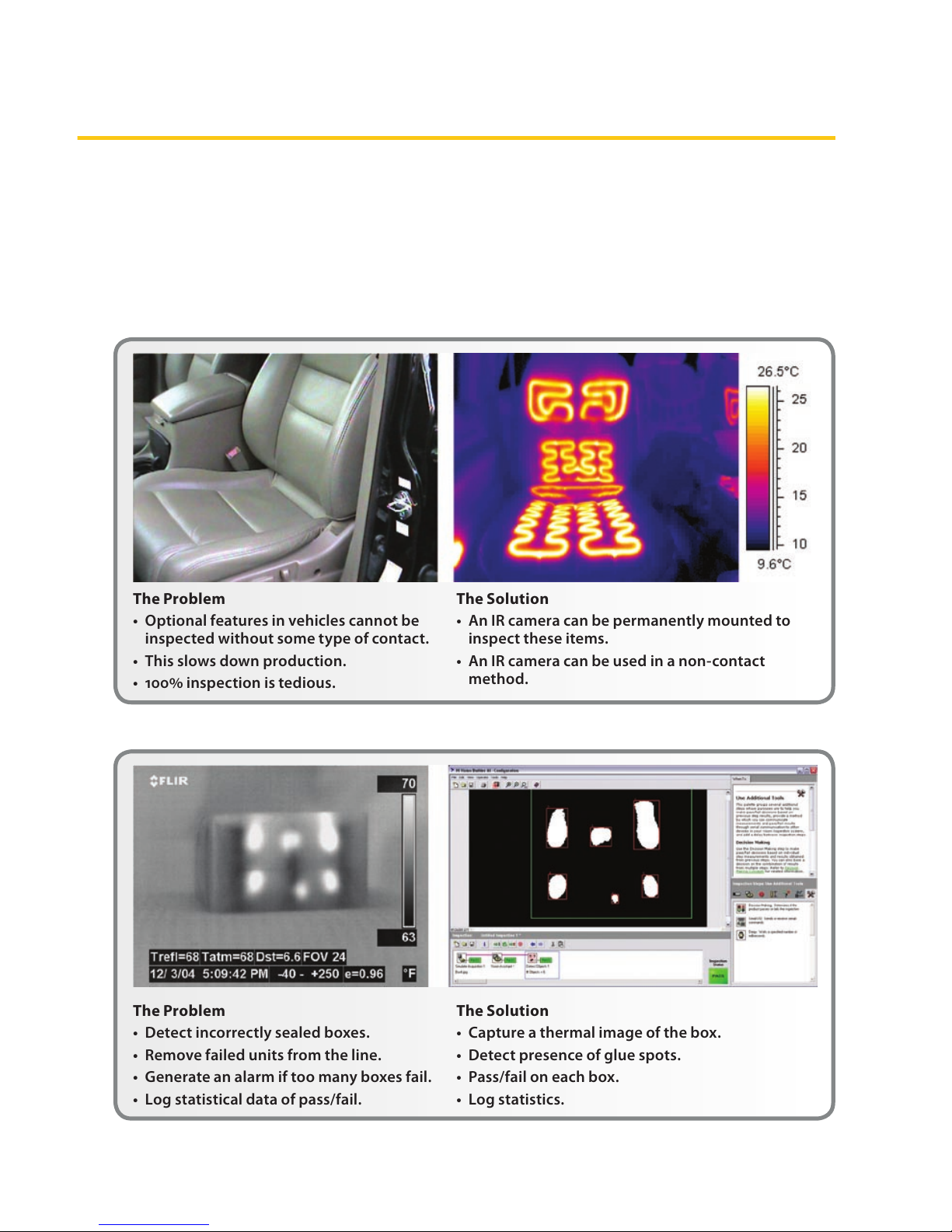
Production Testing of Car Seat Heaters
Problem: Using contact temperature
sensors to assure proper operation of
optional car seat heaters slows down
production and is inaccurate if sensors
are not properly placed.
Solution: An IR camera can detect
thermal radiation from the heater
elements inside the seats and provide
an accurate non-contact temperature
measurement.
This quantitative measurement can be
made with a camera that is permanently
mounted on a xture that is swung
into measurement position when
the car reaches a designated point
on the assembly line. A monitor near
that position provides an image with
a temperature scale that reveals the
temperature of the car seat heater
elements, as shown in Figure 2.
The Problem
• Operatorscannotseethroughthesteam
cloudcausedbycondensationincoolerair
temperatures.
The Solution
• IRoersanotherpairof“eyes”tosee
throughthesteamintothelogvatfor
properlogalignment.
Figure 1. Plywood mill application
Page 9
3
Typical Monitoring and Control Applications
Packaging Operations
Problem: On a high-speed packaging
line, ecient methods for nondestructive testing of a glued box seal
are scarce, and most tend to be very
cumbersome. In addition, the glue
application method has a good deal of
variability that must be monitored and
recorded with statistical quality control
routines.
Solution: Since the glue is heated prior
to application, its temperature and
The Problem
• Optionalfeaturesinvehiclescannotbe
inspectedwithoutsometypeofcontact.
• Thisslowsdownproduction.
• 100%inspectionistedious.
The Solution
• AnIRcameracanbepermanentlymountedto
inspecttheseitems.
• AnIRcameracanbeusedinanon-contact
method.
Figure 2. Production testing of car seat heater elements
The Problem
• Detectincorrectlysealedboxes.
• Removefailedunitsfromtheline.
• Generateanalarmiftoomanyboxesfail.
• Logstatisticaldataofpass/fail.
The Solution
• Captureathermalimageofthebox.
• Detectpresenceofgluespots.
• Pass/failoneachbox.
• Logstatistics.
Figure 3. Machine vision box seal quality control
Page 10

4
Chapter 1
locations on the box lid can be monitored
with an IR camera. Moreover, the image
can be digitized in a way that allows this
information to be stored in a statistical
quality control database for trend analysis
and equipment monitoring as shown in
Figure 3.
This is an example of using dierential
temperature as a proxy for another
variable. In this case, temperature
replaces mechanical methods of
inspection/testing.
Summary
The automation examples presented
in this chapter have barely scratched
the surface of the application space
that smart IR cameras can serve. In
the following chapters, more detailed
examples will be presented along
with practical information on the
implementation of automated systems
that exploit the advantages of IR cameras.
These chapters are organized according
to the major types of applications that
typically use IR cameras:
Remote thermographic monitoring•
Non-contact temperature •
measurement for automated processes
Combining IR machine vision with •
temperature measurement
Real-time control and monitoring – •
issues and answers
Page 11

5
Remote IR MonitoringChapter
Remote IR Monitoring
Overview
Infrared radiation is emitted by all objects
at temperatures above absolute zero
and is detectable by IR cameras. Since
these cameras have various means of
communicating thermographic images
and temperatures to remote locations,
they are ideal for remote and unattended
monitoring. Moreover, smart IR cameras
(those with built-in logic, analytics, and
data communications), can compare
the temperatures obtained from their
thermographic images with user-dened
settings. This allows the camera to
output a digital signal for alarm and
control purposes, while also providing
live images.
IR Camera Operation
IR camera construction is similar to
a digital video camera. The main
components are a lens that focuses IR
onto a detector, plus electronics and
software for processing and displaying
thermographic images and temperatures
on an LCD or CRT monitor (Figure 1).
Instead of a charge coupled device
that video and digital still cameras use,
the IR camera detector is a focal plane
array (FPA) of micrometer size pixels
made of various materials sensitive to
IR wavelengths. FPA resolution ranges
from about 80×80 pixels up to 1024×1024
pixels. In some IR cameras, the video
processing electronics include the logic
and analytical functions mentioned
earlier. Camera rmware allows the
user to focus on a specic area of the
FPA or use the entire detector area
for calculating minimum, maximum,
and average temperatures. Typically,
temperature measurement precision is
±°C or better.
The camera lens and distance to the
target object results in a eld of view
(FOV) that determines the spot size
covered by each pixel. The pixel’s analog
output represents the intensity of heat
energy received from the spot it covers
on the target object. In FLIR IR cameras,
the A/D converters that digitize the pixel
output have resolutions that range from
8 bits (28 or 0–255 pixels) up to 14 bits
(214 or 0–16383 pixels). The thermographic
image seen on the monitor screen is
the result of a microprocessor mapping
these pixel output values to a color or
gray scale scheme representing relative
temperatures. In addition, radiometric
information associated with the heat
energy impinging on a pixel is stored
for use in calculating the precise
temperature of the spot covered by
that pixel.
IR In
Optics
NIR
MWIR
LWIR
Video
Processing
Electronics
Detector Cooling
Digitization
User Interface
User Control
Video Output
Digital Output
Synchronization In/Out
System Status
Figure 1. Simplied block diagram of an IR camera
Page 12

6
Chapter
Hence, IR cameras with these capabilities
operate much like other types of smart
temperature sensors. Their calibrated
outputs can be accessed via one or more
communication interfaces and monitored
at a remote location. Images saved from
these cameras are fully radiometric1 and
can be analyzed o-line with standard
software packages, such as those
available from FLIR.
Important Criteria in Remote
Monitoring Systems
When considering an IR camera for a
remote monitoring system, some of the
important variables to consider are:
Spot size – the smallest feature in a •
scene that can be measured
FOV (Field of View) – the area that the •
camera sees
Working distance – distance from the •
front of the camera lens to the nearest
target object
Depth of eld – the maximum depth of •
a scene that stays in focus
Resolution – the number of pixels and •
size of the sensor’s active area
NETD (Noise Equivalent Temperature •
Dierence) – the lowest level of heat
energy that can be measured
Spectral sensitivity – portion of •
the IR spectrum that the camera is
sensitive to
Temperature measurement range, •
precision, and repeatability – a
function of overall camera design
1 Radiometry is a measure of how much energy is
radiating from an object, as opposed to thermography,
which is a measure of how hot an object is; the two are
related but not the same.
Another fundamental consideration
is which portion of a camera’s FOV
contains the critical information
required for monitoring purposes. The
objects within the FOV must provide an
accurate indication of the situation being
monitored, based on the temperature
of those objects. Depending on the
situation, the target objects may need
to be in the same position consistently
within the camera’s FOV. Other
application variables related to the
monitored scene include:
Emissivity of the target objects•
Reected temperatures within the FOV•
Atmospheric temperature and •
humidity
These topics will be covered in more
detail in a subsequent chapter.
Remote Asset Monitoring
One type of application where IR cameras
are very useful is in remote monitoring
of property, inventory, and other assets
to help prevent loss and improve safety.
Frequently, this involves storage facilities,
such as warehouses or open areas for
bulk materials. The following example
can serve as a general model for setting
up an IR camera monitoring system for
this type of application.
Hazardous Waste Storage Monitoring. In
this application barrels of chemical waste
products are stored in a covered facility,
but one in which they cannot be totally
protected from moisture. Thus, there is
the possibility of leaks or barrel contents
becoming contaminated by air and
moisture, causing a rise in temperature
due to a chemical reaction. Ultimately,
there is a risk of re, or even an explosion.
Page 13
7
Remote IR Monitoring
While visible light cameras might be
used in such an application, there often
is a line-of-sight problem where many
of the barrels cannot be seen, even with
multiple cameras positioned throughout
the storage area. In addition, smoke or
ames would have to be present before
a visible light camera could detect a
problem. This might be too late for
preventative measures to be taken.
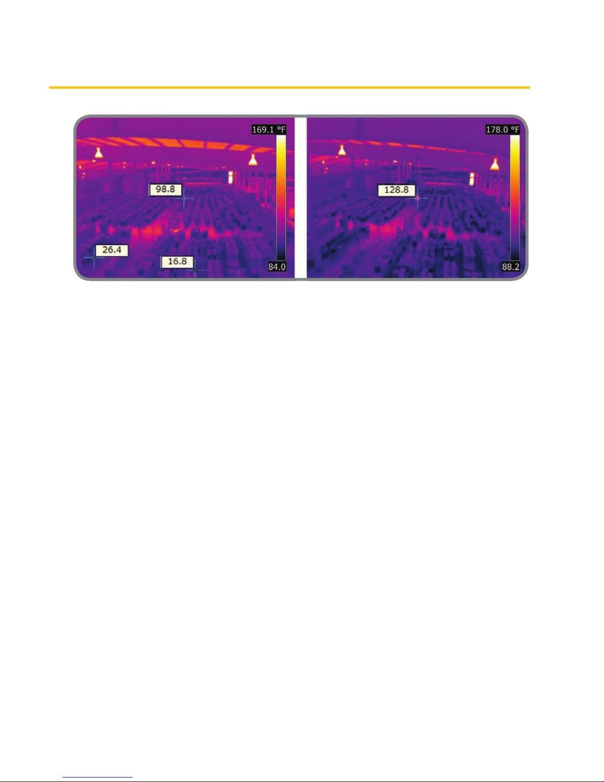
In contrast, stand-alone IR cameras
monitoring the facility can detect a
temperature rise within their FOV before
re occurs (Figures 2a and 2b).
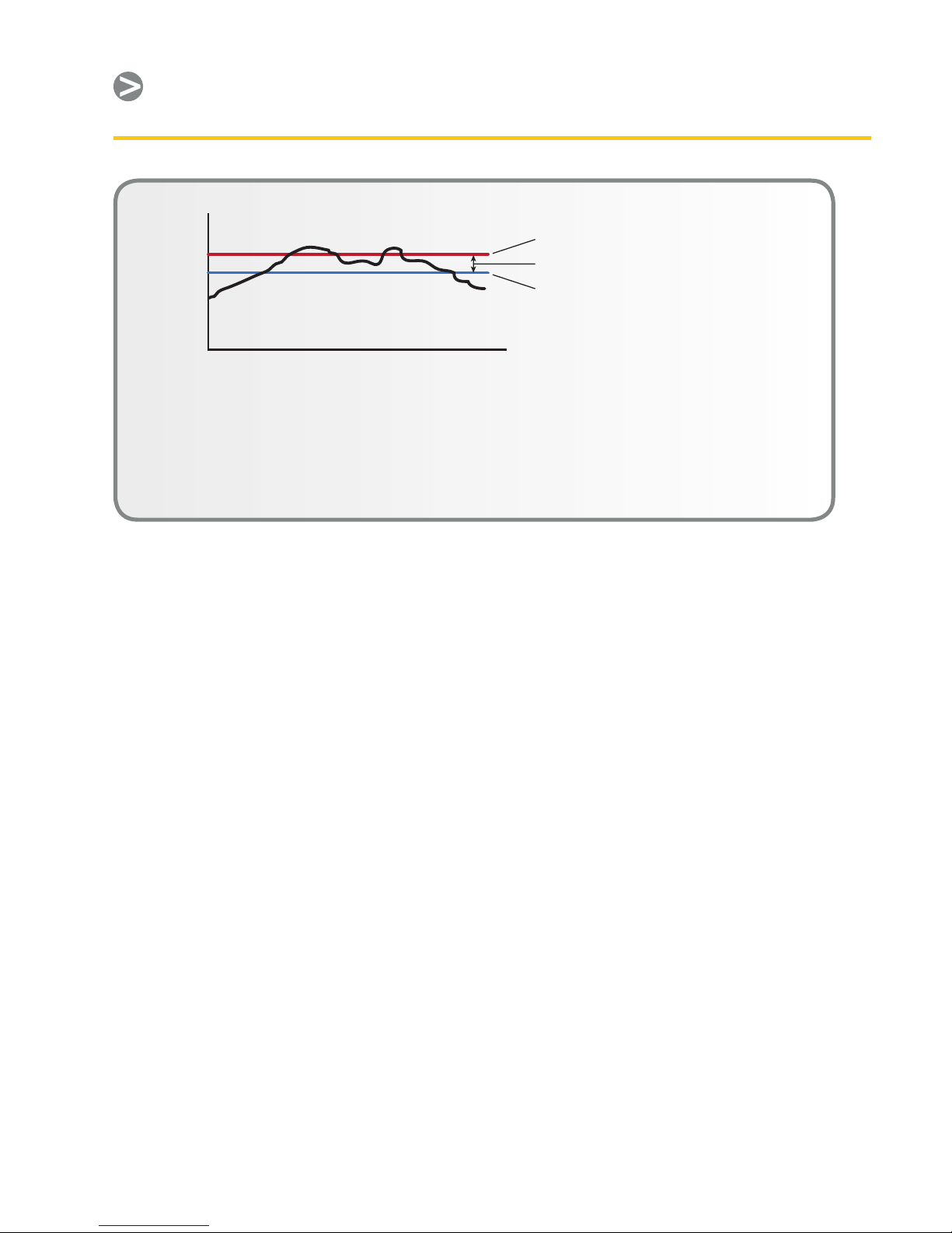
Depending on the camera manufacturer,
several monitoring options are available.
For instance, the FLIR A320 camera
allows a threshold temperature value to
be set internally for alarm purposes. In
addition, the camera’s logic and clock
functions can be congured so that a rise
in temperature must be maintained for a
certain period of time before an alarm is
sent. This allows the system to ignore a
temporary temperature rise in a camera’s
FOV caused by a forklift entering the area
to add or remove barrels. Furthermore,
a hysteresis function can also be used to
prevent an alarm from turning o until
the detected temperature falls well below
the setpoint (Figure 3).
Cameras with a digital I/O interface
typically provide an OFF/ON type of
output for alarm purposes. The digital
I/O output is either o or on; when on, it
is typically a DC voltage or current. For
example, the digital I/O output from a
FLIR A320 camera is 10–30VDC for loads
of 100mA or less. Typically, the digital
I/O output is sent to a PLC (Programble
Logic Controller) that controls the portion
of an alarm system associated with the
monitored area.
A good way to set up the alarm system
is to have all cameras congured so they
have a high level digital output when the
temperature is below the alarm condition
that holds a PLC in its non-alarm state.
When the alarm setpoint temperature is
detected, the camera’s digital I/O output
goes low (typically zero volts) after an
appropriate time delay, causing the PLC
Figure 2a. IR image of a hazardous waste storage
area showing two spot temperature readings
(26.4°F and 16.8°F) that are in the safe range, plus
one reading (98.8°F) that is abnormally high.
Figure 2b. A subsequent image of the same
area shows that the abnormal reading in 2a
has increased further, causing an alarm to
go o.
Page 14
8
Chapter
to go into its alarm state. This creates a
fail-safe system. If power to the camera is
lost, then there is no high level output to
the PLC, which treats that event just as if
a temperature had reached the setpoint,
thereby causing an alarm. This alerts
personnel that they have either lost the
monitoring function or there is indeed a
temperature rise.
Image monitoring. Receiving a warning
based on temperature measurements is
very useful, but the real power of IRbased asset monitoring is in the camera’s
image processing capabilities. Control
room personnel can get live images from
IR cameras that visible light cameras
and other temperature detectors
cannot provide. Again, cameras vary by
manufacturer, but the most versatile ones
oer a variety of data communication
formats for sending thermographic
images to remote locations. Increasingly,
web-enabled cameras are used to allow
monitoring from any location where a PC
is available.
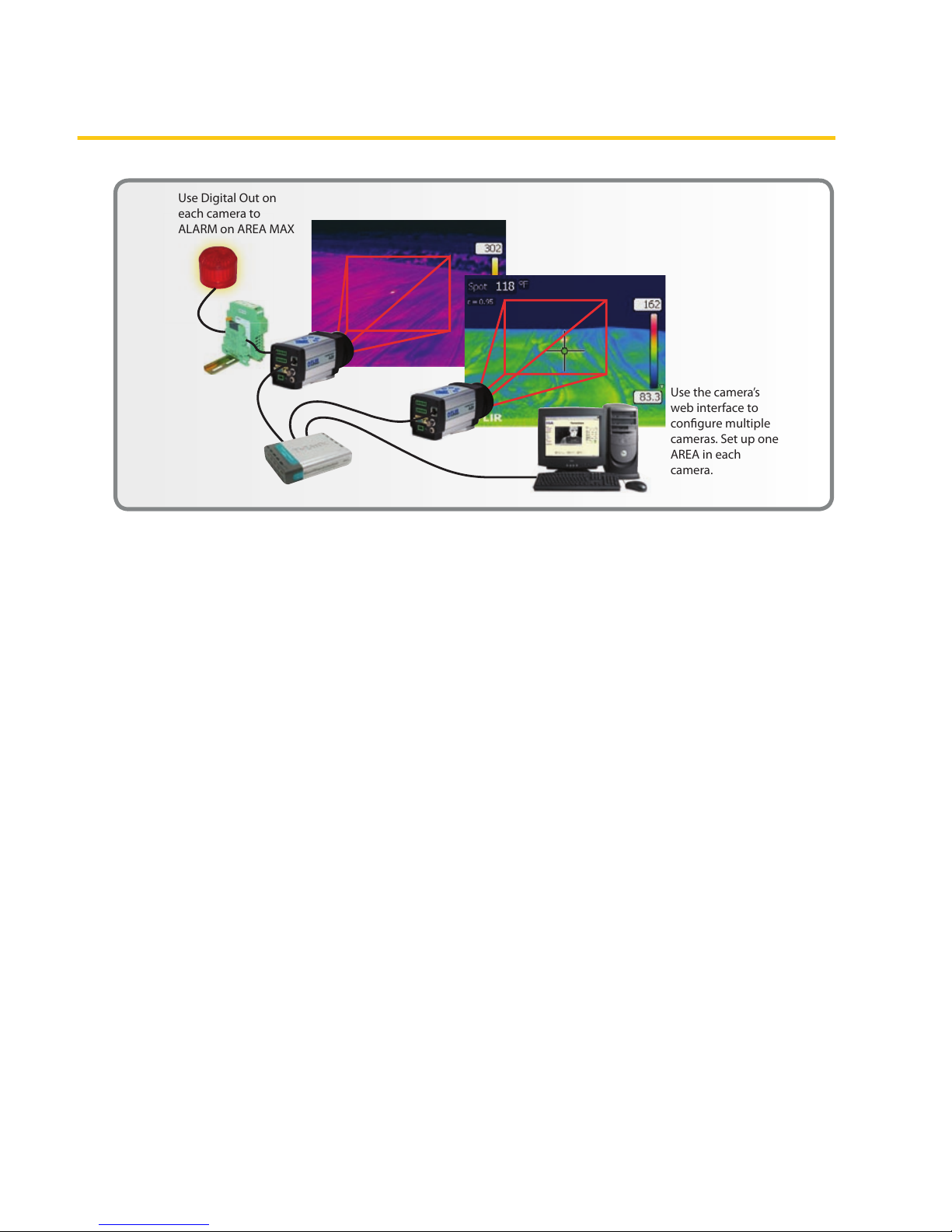
Figure 4 illustrates a system using
the FLIR A320’s Ethernet and TCP/IP
communication protocols in conjunction
with its alarm setpoint capabilities. The
Ethernet portion of the system allows
cable runs of up to 100 meters in length.
By communicating a digital alarm directly
to the PLC, it can immediately activate
a visual and/or audible alarm. The visual
alarm can appear on an annunciator
panel telling the operator where the
alarm originated; the operator then goes
to the PC to look at live image(s) of that
location. Images and temperature data
can be stored for future reference and
analysis.
A320 cameras can also be congured to
automatically send temperature data
and images to a PC via e-mail (SMTP) or
FTP protocol whenever the temperature
setpoint is reached, thereby creating a
record for subsequent review.
Time
Temperature
Threshold
T e mperature
(Warning On)
Wa rning O
T e mperature
Deadband
O Te mp = On Te mp – Deadband
Hysteresis
• Also known as deadband
• Can be thought of as another threshold setting – where
the smart sensor resets the alarm that was generated
when the original setpoint was compromised
• Used to prevent signal “chatter”
Figure 3. Hysteresis is an important signal processing characteristic of smart IR cameras, which
makes monitoring and control functions much more eective.
Page 15
9
Remote IR Monitoring
In conjunction with a host controller
running FLIR’s IR MONITOR (or other
suitable software), temperature data can
be captured for trend analysis. The A320
can also supply a digital compression
of the camera’s analog video signal,
which can be sent as MPEG-4 streaming
digital video over an Ethernet link to a PC
monitor. IR MONITOR can be used to set
up temperature measurements, image
capture, and camera display functions.
This application allows the PC to display
up to nine camera images at a time
and switch between additional camera
groups as needed. The FLIR IP CONFIG
software can be used to set up each
camera’s IP address.
After the cameras are congured, the
PC used for monitoring does not need
to remain on the network continually.
By using the FTP and SMTP protocols
within the camera, the user can receive
radiometric images upon alarm events
or on a time based schedule. Also, any
available PC with a web browser can be
used to access the cameras web server
for live video and basic control. This web
interface is password protected.
Most IR cameras have an analog
video output in a PAL or NTSC format.
Therefore, another image monitoring
possibility is to use a TV monitor to
display thermographic video. A single
control room monitor can be used with
a switch to view live images from each
camera sequentially. When the cameras
are properly congured, control room
personnel can view scaled temperature
readings for any point or area (minimum,
maximum, and average) in that image.
(See color scales in the screen capture
images depicted in Figure 2.) Not only
will the operator know when there
is excessive heat, he or she can see
where it is.
Another example of the innovative
functions available in camera rmware
or external software is a feature called
Figure 4. An example of one type of system conguration for remote IR camera monitoring. The
system uses a digital alarm output for annunciating an over-temperature condition and transmits
streaming MPEG-4 compressed video that allows the scene to be viewed on a PC monitor.
Use Digital Out on
each camera to
ALARM on AREA MAX
Use the camera’s
web interface to
congure multiple
cameras. Set up one
AREA in each
camera.
Page 16
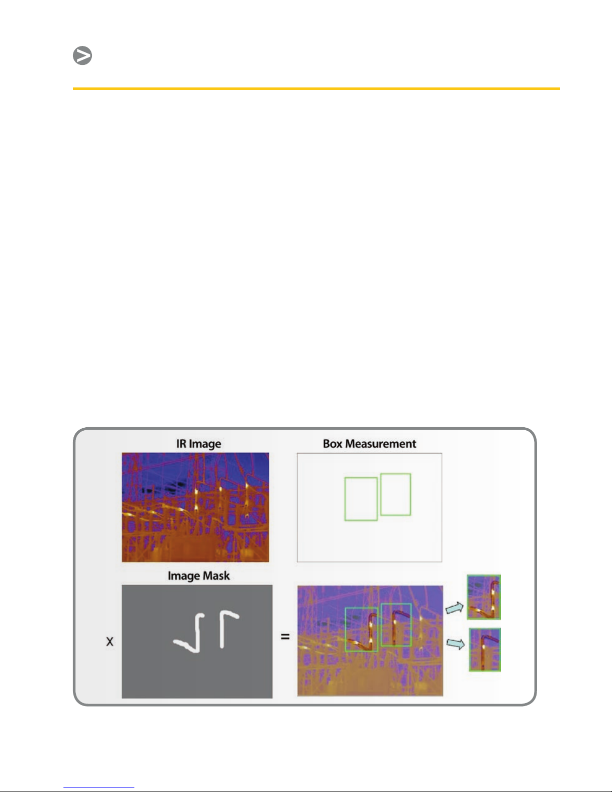
10
Chapter
image masking. This enables the user
to pre-select specic areas of interest
for analysis of temperature data. This
is illustrated in Figure 5, which shows
continuous monitoring of substation
hotspots that indicate problem areas.
A similar type of pattern recognition
software can be used for automated
inspection in metal soldering and
welding and in laser welding of
plastic parts. IR cameras can see heat
conducting through the nished parts
to check the temperature of the areas
where parts are joined together against
a stored value. In addition, the software
can learn a weld path to make sure this
path is correct, which is accomplished
by programming the specic pixels in
an image to be used by the software for
this purpose. Alternatively, the program
developer can save an image of a
“perfect” part and then have the software
look for minimum, maximum, or delta
values that tells the equipment operator
if a part passes inspection. The car seat
heater inspection described in Chapter 1
can be an example of this, and the same
principle is used in the inspection of car
window heater elements by applying
power to them and looking at their
thermographic image.
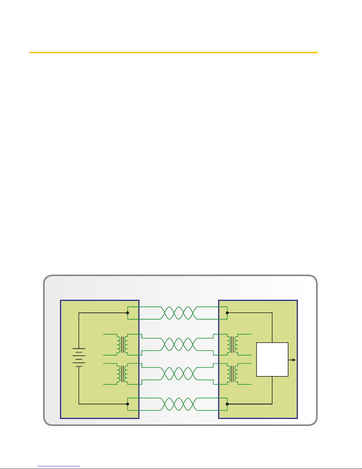
Power over Ethernet. It should be noted
that a camera with Ethernet connectivity
can be powered from a variety of sources,
depending on its design. Typically, a
connection for an external DC supply is
used, or where available, the camera is
powered via PoE (Power over Ethernet).
PoE uses a power supply connected to
the network with spare signal leads not
Figure 5. Masking functionality of the FLIR A320 IR camera, which is also available in some third
party software programs.
Page 17
11
Remote IR Monitoring
otherwise used in 10/100baseT Ethernet
systems. Various PoE congurations are
possible. Figure 6 depicts one in which
the power source is located at one end
of the network. (Gigabit Ethernet uses all
available data pairs, so PoE is not possible
with these systems.)
PoE eliminates the need for a separate
power source and conduit run for
each camera on the network. The
only additional cost is for some minor
electrical hardware associated with PoE.
Many applications encompass areas that
exceed the maximum Ethernet cable
run of 100m. In those cases, there are
wireless and beroptic converter options
that provide o-the-shelf solutions
for communicating over much greater
distances. These are frequently used in
the bulk material storage applications
described below.
Additional Asset Monitoring Situations
Bulk Material Storage. Many bulk
materials are stored in open yards where
air and moisture can help promote
decomposition and other exothermic
reactions that raise the temperature of
the pile. This brings with it the threat
of re, direct monetary loss, and safety
issues for personnel. In addition, there
is the risk of consequential damages
caused by res, including loss of nearby
property, water damage resulting from
re-ghting, and production shutdowns.
Materials that are especially prone to
spontaneous combustion include organic
wastes (compost, etc.), scrap paper
for recycling, wood, coal, and various
inorganic chemicals, such as cement and
chlorine hydrates. Even in the absence
of spontaneous combustion, many
bulk materials like plastics pose a re
hazard due to sparks or other external
ignition sources.
1
5
Spare Pair
Signal Pair
Signal Pair
4
2
TX
+48V
–
RX
DC/DC
Converter
3
6
1
5
4
2
3
6
RX TX
5
Spare Pair
4
5
4
Power Sourcing
Equipment (PSE)
Powered
Device (PD)
Figure 6. Schematic depicting spare-pair PoE delivery using the endpoint PSE arrangement.
Page 18
12
Chapter
In most cases, prevention is less costly
than a cure, and the best prevention is
continuous monitoring of the materials.
The cost of an automated temperature
monitoring system using IR cameras is
a modest and worthwhile investment.
System design can take the same form as
the one described earlier for hazardous
waste barrels. Cameras are congured
to generate a direct alarm output to an
operator when user-dened maximum
temperature thresholds are exceeded.
Audible and visual alarms in a control
room draw the operator’s attention to a
possible spontaneous re development.
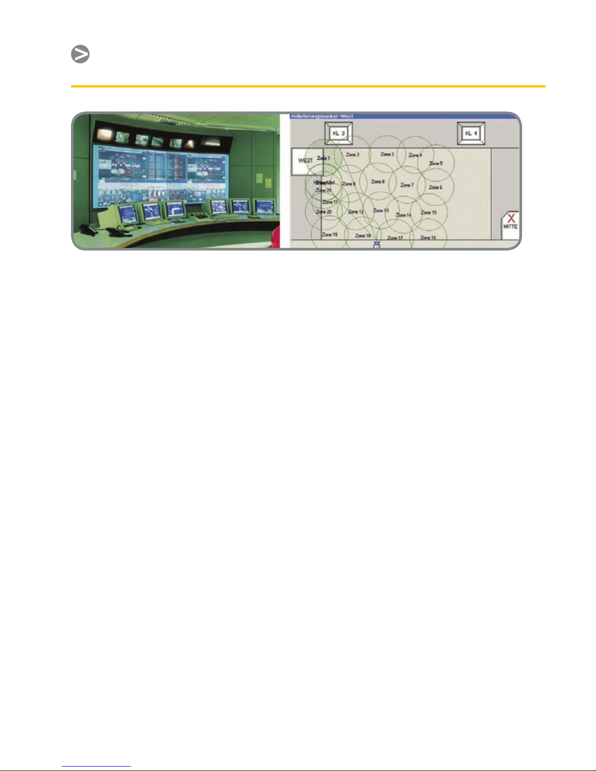
Various types of software have been
developed to isolate trouble spots, such
as the waste pile zone monitoring system
depicted in Figure 7.
Although self-ignition usually starts
within the bottom layers of a stock pile,
continuous monitoring of the surface
reveals hot spots at an early stage (Figure
8), so measures can be taken to prevent
a major re from breaking out. Large
storage yards generally require multiple
cameras for total coverage, with the
cameras mounted on metal masts above
the stock piles. This calls for cameras with
housings and other features designed
for reliable operation in harsh industrial
environments.
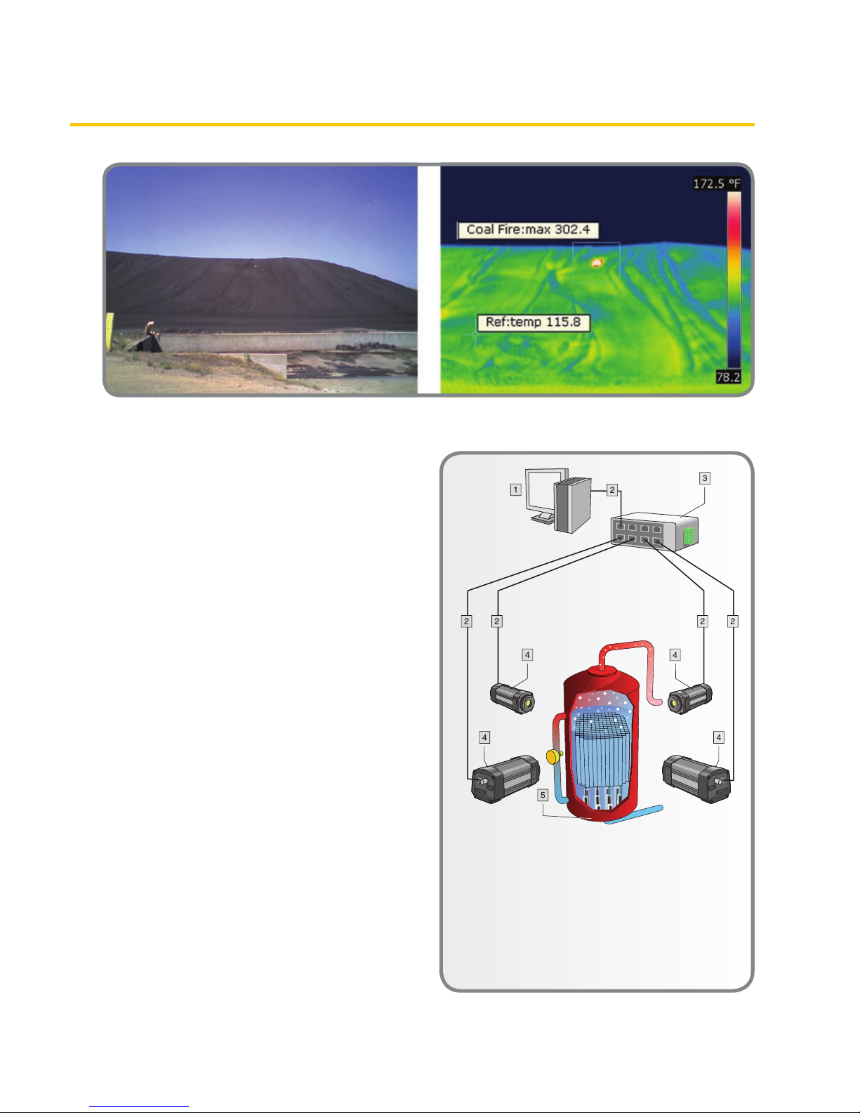
Critical Vessel Monitoring (CVM). There
are several applications where the
temperature of a vessel and its contents
are critical. The vessels could be used
for chemical reactions, liquid heating,
or merely storage. For large vessels,
the use of contact temperature sensors
poses problems. One reason could be
non-uniform temperatures throughout a
vessel and across its surface. This would
require a large number of contact type
sensors, whose installations can become
quite costly.
For most CVM applications, a few IR
cameras can image nearly 100% of a
vessels surface (Figure 9). Moreover, they
can measure the surface temperature of
the CVM to trend and predict when the
internal refractory will break down and
compromise the mechanical integrity of
the system. If specic regions of interest
(ROIs) must be focused on, IR camera
rmware (or external PC software) allows
the selection of spot temperature points
or areas for measurement.
Again, some variation of the systems
described earlier can be used. Depending
Figure 7. Control room for waste pile processing, and screen capture of the zone monitoring layout,
which uses a FLIR IR camera on a pan-tilt mount for re hazard warning.
Page 19
13
Remote IR Monitoring
Figure 8. Visible light and IR images of a coal pile – the thermographic image clearly identies a hot
spot that is a re about to erupt.
on the application environment, an
explosion proof housing for the camera
may be a requirement. HMI (humanmachine interface) software, such as
SCADACAM iAlert from Pivotal Vision,
can be used to provide a monitoring
overview. This has the ability to combine
all of the camera images into a single
spatial representation of the monitored
area – in this case, a attened-out view
of the vessel. This view can be updated
continuously for a near-real-time
thermographic representation.
Electrical Substation Monitoring. Reliable
operation of substations is crucial for
uninterrupted electrical service. Besides
lightning strikes and large overloads,
aging equipment and connections are
a major cause of infrastructure failures
and service interruptions. Many of these
failures can be avoided with eective
preventative maintenance monitoring.
Often, the temperatures of transformers,
breakers, connections, etc. will begin to
creep up before a catastrophic failure
occurs. Detection of these temperature
increases with IR cameras allows
preventative maintenance operations
Figure 9. CVM monitoring example showing
camera locations, network connections, and PC.
1 Computer
2 CAT-6 Ethernet cable with RJ45
connectors
3 Industrial Ethernet switch with PoE
4 ThermoVision™ A320 cameras
5 Industrial process to be monitored,
e.g., a gasier
Page 20

14
Chapter
before an unplanned outage happens.
(See Figure 10.)
The cameras can be installed on a pan/
tilt mounting mechanism to continually
survey large areas of a substation (Figure
11). A few cameras can provide real-time
coverage of all the critical equipment
that should be monitored. In addition
to preventative maintenance functions,
these cameras also serve as security
monitors for intrusion detection around
the clock.
By combining the cameras’ Ethernet
and/or wireless connectivity with a
web-enabled operator interface, live
images can be transmitted to utility
control rooms miles away. In addition,
trending software can be used to detect
dangerous temperature excursions and
notify maintenance personnel via email
and snapshot images of the aected
equipment.
These features and functions are already
in place at leading utility companies in
the U.S., such as Exel Energy’s “Substation
of the Future.” Companies such as
Exel consider IR monitoring a strategic
investment in automation, which is
part of a common SCADA (Supervisory
Control And Data Acquisition) platform
for maintenance and security operations.
The most advanced systems provide
time-stamped 3-D thermal modeling
of critical equipment and areas, plus
temperature trending and analysis. A
company-wide system of alerts provides
alarms on high, low, dierential, and
ambient temperatures within or between
zones in real time.
The previous examples represent just a
few applications that can benet from
remote IR camera monitoring. A few
other applications where IR temperature
monitoring is being used include:
Oil and gas industries (exploration •
rigs, reneries, are gas ues, natural
gas processing, pipelines, and storage
facilities)
Electric utilities (power generation •
plants, distribution lines, substations,
and transformers)
Figure 10. Visible light and IR images of a substation showing a transformer with excessive
temperature.
Page 21
15
Remote IR Monitoring
Figure 11. Example pan/tilt mounting system.
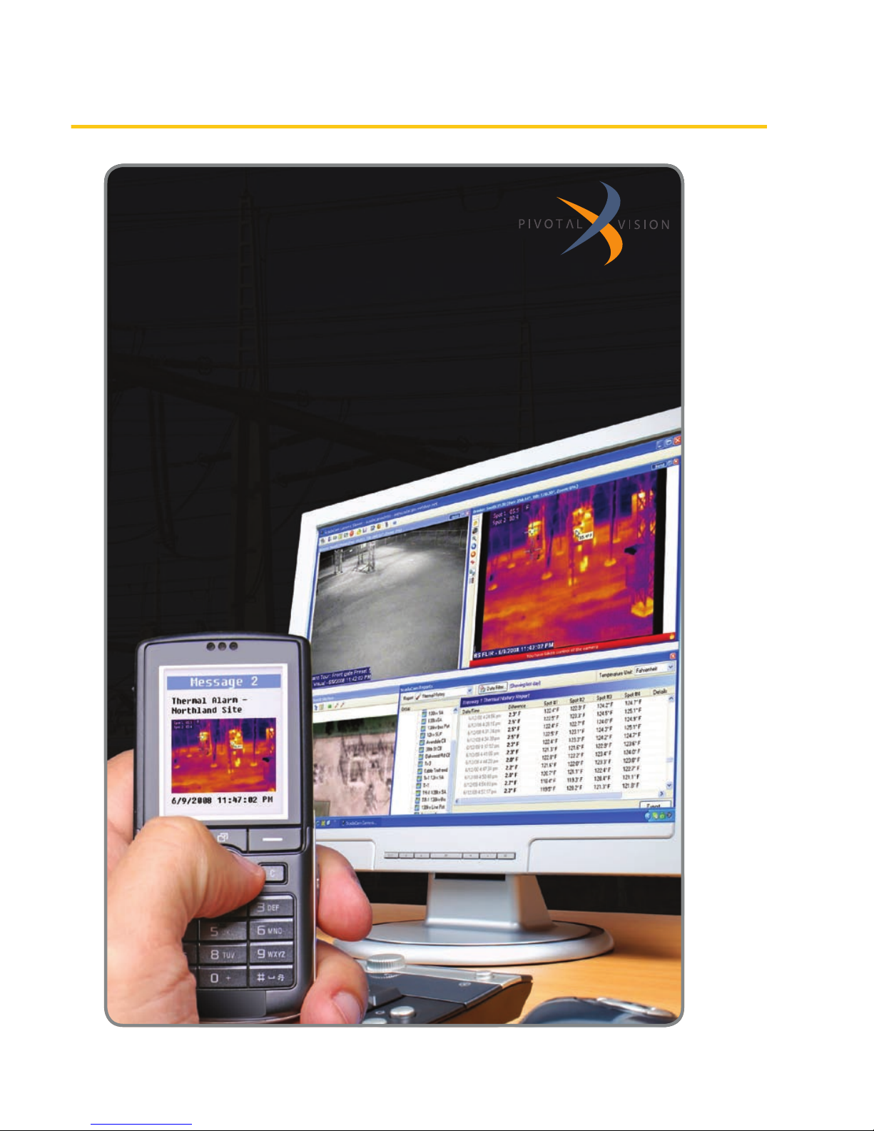
Smarter surveillance for a smarter grid
Meet ScadaCam Intelligent Surveillance, the only system in its price range
that can automatically perform site patrols, monitor equipment temperature,
and scan for security breaches without human supervision.
By combining visual, thermal imaging, and thermographic cameras into a
multifunctional operations and security automation tool, ScadaCam can
detect, validate, and alarm you of problems that could otherwise result in a
major outage – before they occur.
See it in action at www.pivotal-vision.com/tryit
Page 22

16
Chapter
Predictive and preventative •
maintenance (continuous/xed
position monitoring of critical
equipment)
Besides these, there are many qualitative
remote monitoring applications where
imaging is the predominant feature. For
example, IR cameras can be used as part
of an early warning system for forest
res (Figure 12), detecting blazes before
signicant amounts of smoke appear.
Another example is using IR imaging to
look through condensation vapor that
would otherwise obscure an operator’s
view of equipment and processes. This is
being used in coking plants, veneer mills,
and plywood log handling operations,
among others (see Chapter 1, Figure 1).
Summary
As noted in the text, IR camera
temperature data may be used for
qualitative monitoring or for quantitative
temperature measurement and control.
In the former, thermal images are
obtained and interpreted based on
temperature contrast. It can be used
to identify image areas that correlate
to sub-surface details, liquid levels,
refractory, etc.
Quantitative measurements generally
require the IR camera to accurately
determine the temperature dierence
between the target object and its
surroundings. In remote monitoring, this
allows the temperature data to be used
for alarm purposes or to even shut down
equipment. Since temperature changes
slowly in many situations, the near-real-
time data communications of smart IR
cameras are more than adequate for
alarm and control systems.
Figure 12. Ngaro’s IRIS® Watchman forest re early warning system uses a FLIR IR camera.
Page 23

17
Temperature Measurement
for Automated Processes
Temperature Measurement
for Automated Processes
Background
In Chapter the emphasis was on
specic applications where a single
temperature threshold is programmed
into an IR camera, and when the
threshold is reached an alarm is
triggered through a PLC. Multiple
cameras are often required, but viewing
an IR cameras’ thermographic image
is a secondary consideration – to
verify an alarm condition. Chapter 3
focuses on applications where multiple
temperatures within a single camera’s
FOV are important, and that information
is used for some sort of process control
function. In these applications, the
camera is typically integrated with other
process control elements, such as a PC or
PLC using third party software and more
sophisticated communication schemes.
Typical Camera Measurement
Functions
Many IR cameras provide the user with
dierent operating modes that support
correct temperature measurements
under various application conditions.
Typical measurement functions include:
Spotmeter•
Area•
Image mask•
Delta T•
Isotherm•
Temperature range•
Color or gray scale settings•
The last two are used with the others to
provide a visual indication of the range
of temperatures in the camera’s FOV.
Generally, spot and area temperatures
tend to be the most useful in monitoring
and control applications, and most
cameras allow multiple spots or areas to
be set within the thermographic image.
For example, the FLIR A320 camera
supports up to four spots and four areas.
Cursor functions allow easy selection of
an area of interest, such as the crosshairs
of the spot readings in Figure 1. In
addition, the cursor may be able to select
circlular, square, and irregularly shaped
polygon areas.
Figure 1. IR image of a printed circuit board
indicating three spot temperature readings.
Image colors correspond to the temperature
scale on the right.
The spotmeter nds the temperature
at a particular point. The area function
isolates a selected area of an object or
scene and may provide the maximum,
minimum, and average temperatures
inside that area. The temperature
measurement range typically is
selectable by the user. This is a valuable
feature when a scene has a temperature
range narrower than a camera’s full-
scale range. Setting a narrower range
allows better resolution of the images
and higher accuracy in the measured
Chapter 3
Page 24

18
Chapter 3
Figure 2. Gray scale images of a car engine – the left view has white as the hottest temperature and
the right view shows black as the hottest.
temperatures. Therefore, images will
better illustrate smaller temperature
dierences. On the other hand, a
broader scale and/or higher maximum
temperature range may be needed to
prevent saturation of the portion of the
image at the highest temperature.
As an adjunct to the temperature range
selection, most cameras allow a user
to set up a color scale or gray scale to
optimize the camera image. Figure 2
illustrates two gray scale possibilities.
In Figure 1, a so-called “iron scale” was
used for a color rendering. In a manner
similar to the gray scale above, the
hottest temperatures can be rendered
as either lighter colors or darker colors.
Another possibility is rendering images
with what is known as a rainbow scale
(Figure 3).
While choice of color scale is often a
matter of personal preference, there may
be times when one type of scale is better
than another for illustrating the range of
temperatures in a scene.
Figure 3. Rainbow scale showing lower
temperatures towards the blue end of the
spectrum.
Application Examples
Go/No-Go. In these applications, one or
more temperatures are monitored to
make sure they meet process criteria,
and machinery is shut down or product
rejected when a measured temperature
goes above or below the setpoint. A
good example of this is a manufacturer
of automotive door panels that uses
IR cameras to monitor and measure
part temperatures prior to a molding
procedure.
Page 25

19
Temperature Measurement for Automated Processes
This process starts with reinforcing parts
that have been stored in a warehouse.
In either the warehouse or during
transport to the molding line, these
parts can become wet due to moisture
condensation or exposure to inclement
weather. If that happens, they may not
reach a high enough temperature in the
molding press and nished panels will be
of poor quality.
The parts go into the press two at a
time from a conveyor where they are
sealed together and the nished door
panel is molded into the required shape
for a specic car model. If the parts are
wet, this creates steam in the press and
causes mold temperature to be too low.
However, it was found that movement of
wet parts on the conveyor causes their
temperature to be lower than normal. So,
just before the parts go into the press,
the conveyor stops and an IR camera
makes a non-contact measurement
of their temperature. The diagram in
Figure 4 is typical for this type of quality
control application.
The IR camera’s area tools are applied to
the thermographic image to check for
the minimum allowable temperature of
the two parts. If either temperature is
below the setpoint (typically, the ambient
temperature), then a digital I/O output to
a PLC causes an alarm to be sounded and
Figure 4. Typical Go/No-Go QC inspection system using IR cameras.
1 Computer or PLC
2 CAT-6 Ethernet cable with
RJ45 connectors
3 Industrial Ethernet switches
with ber optic ports
4 Fiber optic cable
5 ThermoVision™ A320 or A325
cameras
6 Industrial process to be
monitored, e.g., items on a
conveyor belt
Page 26

20
Chapter 3
the molding line is halted so the parts can
be removed.
For OEMs, preventing bad panels from
getting to the end product avoids a
potential loss of business. Warranty
replacement of a door panel after an end
customer takes possession of the car is an
expensive proposition for the OEM.
The trick is to make sure the camera is
measuring the temperature of the parts
and not the oor beneath the conveyor,
which is within the camera’s FOV and
typically much cooler. This occurs when
the parts are not in the proper position. A
photoelectric detector tells the PLC when
the parts enter the press area; otherwise
its ladder logic ignores the alarm output
from the camera.
Continuous Process Monitoring.
Temperature is an important variable
in many processes. It can either be an
integral part of a process or act as a
proxy for something else. The following
describes an example that encompasses
both of these situations.
Articial ber production typically
involves a continuous extrusion process.
Multiple strands may be extruded
simultaneously or, in the case of nonwoven sheets, a web process may be
involved. In either case, monitoring
the temperature of the material as it
comes out of the extruder can detect
strand breakage or material blockage
and backup in the process. Using an IR
camera for unattended monitoring can
catch these malfunctions early, before
a huge mess is created that causes
a long machinery outage and costly
production losses. In addition, the actual
temperature readings can be used for
trend analysis.
Depending on the application, either the
spot or area measurement functions of
the camera can be used. In the latter case,
it is likely that the application would take
advantage of all the area measurement
capabilities – minimum, maximum, and
average temperatures of the dened
area. If any of these were to fall outside
the user-dened limits, the application
program running on a PC or PLC
could instantly shut down the process
machinery.
In one such application, FLIR
customized the camera rmware to
allow simultaneous monitoring of up
to 10 dierent areas. Figure 5 shows a
monitored area covering six ber strands
coming out of the extruder, along with an
alarm setpoint temperature in the upper
left corner.
Figure 5. Monitoring of articial bers coming
out of an extruder.
As in the case of many remote monitoring
applications, the user may choose to
route the camera’s analog video to a
control room monitor. For cameras
with an Ethernet connection, digitally
Page 27

21
Temperature Measurement for Automated Processes
compressed (MPEG-4) streaming video
can be available for monitoring on a PC
screen. With FLIR’s A320 camera, images
and alarms can be sent to a remote PC via
TCP/IP and SMTP (email) protocols.
While a visible light camera may be able
to detect broken ber strands, an IR
camera can also provide temperature
measurements for trending and statistical
process control (SPC) purposes. In
addition, some textile processes create
steam or condensation vapors that a
visible light camera cannot see through,
but an IR camera can. Thus, an IR camera
provides multiple functions and is more
cost eective.
Data Communications and
Software Considerations
Dierent cameras have dierent video
frame rates. The frame rate governs how
frequently the thermographic image
and its temperature data are updated.
A typical rate might be every 200ms or
so. The camera’s digital communications
protocol could create a small amount of
additional latency in the update process.
Still, because process temperatures tend
to change slowly, collecting temperature
data at this rate provides a wealth of
information for quality control purposes.
In many IR cameras there is some sort
of serial/socket interface that can be
used for communications with the PC
or PLC that is running a control script,
or application. When a system designer
or user is most familiar with PLCs, the
control algorithm can be built around
a virtual PLC created on a PC, which
emulates actual PLC hardware and logic.
In any case, a human-machine interface
(HMI) is created to monitor data coming
from the camera. The details described
below are based on FLIR’s A320 camera,
but should be representative of most
cameras that transmit data over an
Ethernet link.
The only physical interface for digital
data transfer from the FLIR A320 is the
Ethernet port. Only TCP/IP is supported,
but the camera should work seamlessly
on any LAN when the proper IP address,
netmask, and possibly a gateway is set
up in the camera. The two main ways
of controlling the camera are through
the command control interface and the
resource control interface. Digital image
streaming, data le transfer, and other
functionality is provided through the
IP services interface. A lot of software
functionality is exposed through
software resources. These resources
can be reached through the FLIR IP
Resource Socket Service. This is the
camera’s resource control (serial/socket)
interface. Independent of the physical
Ethernet interface, it is possible to access
the camera system using TCP/IP with
telnet, ftp, http, and FLIR Resource Socket
Services (among others).
Most PLCs provide serial/socket interfaces
for Ethernet. One example is AllenBradley’s EtherNet/IP Web Server Module
(EWEB for short). Another example is HMS
Industrial Network’s Anybus X-Gateway
Ethernet interface module, which can
convert this serial socket interface to
many industrial network protocols, such
as EtherNet I/P, Modbus-TCP, Pronet,
Ethernet Powerlink, EtherCAT, FLNet., etc.
Camera setup and data acquisition is
normally done directly through the FLIR IR
MONITOR and IP CONFIG software running
on a PC. Afterward, the camera can be
Page 28

22
Chapter 3
connected on the network for continuous
monitoring and data logging via PC or
PLC control. Typically, the telnet protocol,
accessed by the Windows® PC running
the application program, is used to query
the camera for data. This protocol is also
available for most PLCs. In either case, this
takes place though the camera’s Resource
Socket Services. (Command syntax is
contained in the camera’s ICD manual; a
few examples are listed in Appendix D.)
The system designer or FLIR would
create the message instructions that
allow the PLC to query the camera for
temperature data and thermographic
images in the same way it is done with PC
control. Alternatively, the PLC can hold
the Ethernet port open and call for the
camera to continuously output data to
this port at the maximum rate possible. In
either case, alarm functions and decision-
making is performed by the application
program running on the PLC (or PC if
applicable). (See Figure 6.) Typically,
temperatures and images collected for
trend analysis and statistical process
control purposes are stored on a separate
server connected to the network, which
is running transaction manager software
for downloading and storing data.
1 Computer, PLC, and/
or transaction manager
server
2 CAT-6 Ethernet cable
with RJ45 connectors
3 Industrial Ethernet
switches with ber optic
ports
4 Fiber optic cable
Wireless access points
6 CAT-6 Ethernet cable
with RJ45 connectors.
Powering the camera
using PoE (Power over
Ethernet)
7 Industrial Ethernet
switch
8 ThermoVision A320
cameras monitoring a
process or other target
objects
Figure 6. Generalized IR machine vision system and its communications network
Page 29

23
Temperature Measurement for Automated Processes
Figure 7. Example of a control and data acquisition option for IR cameras
©2008 National Instruments Corporation. All rights reserved. Nati onal Instruments, NI, and ni.com
are trademarks of National Instruments. Other product and company names listed are trademarks
or trade names of their respective companies. 2008-9522-221-101
>>
Get your free 30-day trial version
at ni.com/vision/vbai
800 891 8841
Inspect Faster
with NI Vision Builder AI
National Instruments Vision Builder for Automated Inspection (AI) now
features an innovative state machine editor, taking you from initial
design to deployed vision application faster than ever. Easily integrate
with existing industrial control hardware – no programming required.
NEW! Vision Builder AI
�
Configurable Machine Vision
�
No Programming Required
�
Acquisition from Thousands of Cameras
2008-9522-221-101-D 4/29/08 10:25 AM Page 1
Page 30

24
Chapter 3
For system developers who are writing
or modifying code with Visual Basic, C++,
etc. for customized applications running
on a PC, there are a few options. FLIR’s
Researcher package supports OLE-2,
the Microsoft standard for linking and
embedding data between applications.
Image and temperature data can be
linked from Researcher into other
compliant applications, such as Excel. The
linked data updates automatically, so if a
temperature value changes in Researcher
it will automatically change in the linked
application. In addition, Researcher
provides an automation interface that
can be used to control the software using
Visual Basic or VBA. Other o-the-shelf
options for OLE control include National
Instruments’ MATLAB and LabVIEW®.
However, none of the aforementioned are
OPC (OLE for Process Control) compatible.
There are other out-of-the-box solutions
that do not require the writing of
application source code. One of these is
IRControl from Automation Technology,
GmbH. IRControl simplies automated
processing of complex tasks with its
built in Automation Interface based on
Microsoft® COM/DCOM. All essential
measurement, analysis, and control
functions for FLIR IR cameras are directly
programmable using macro commands.
This allows the execution of control
scripts automatically based on digital
input events. In addition, IRControl
accepts remote control commands sent
over an RS-232 link. Therefore, remote
control of IRControl by other computers
or PLCs is greatly simplied. The software
also includes a comprehensive report
generator.
Summary
A variety of control and data acquisition
options are available for IR cameras
(see Figure 7). They are similar to those
used with visible light cameras that
are employed in machine vision and
automation systems. IR cameras provide
the added advantage of accurate non-
contact temperature measurements
within a single instrument.
Page 31

25
Combining Machine Vision and
Temperature Measurement
Combining Machine
Vision and Temperature
Measurement
Background
Traditionally, visible light cameras have
been a mainstay in machine vision
systems used for automated inspection
and process control. Many of these
systems also require temperature
measurements to assure product quality.
In numerous cases, an IR camera can
supply both an image of the product
and critical temperature data. If the
application will not benet from
thermographic images and non-contact
temperature measurements, then a
visible light camera is certainly less
expensive. If the opposite is true, then an
IR camera should be considered by the
system designer.
As the sophistication of IR cameras
continues to increase, along with
associated hardware and software, their
use in automated systems is growing
rapidly. Because of their combined
imaging and temperature measurement
capabilities, they can be very cost
eective. The main impediment to their
wider usage is system designers’ lack
of familiarity with IR camera features
and the related standards, systems, and
software that support them. This chapter
supplies a good deal of that information.
Machine Vision Applications
As in the case of visible light cameras,
thermographic cameras and their
associated software can recognize the
size, shape, and relative location of
target objects (i.e., they can do pattern
matching). Moreover, the electronics
in newer IR cameras provide fast signal
processing that allows high video frames
rates (60Hz or higher) to capture relatively
fast-moving parts on a production line.
Their A/D converters combine short
integration times with 14- to 16-bit
resolution, which is critical for properly
characterizing moving targets or targets
whose temperatures change rapidly.
Figure 1. Results of automated inspection of ICs
on a circuit board
One example of the latter is automated
inspection of operating ICs on a circuit
board (Figure 1). In some cases, this
involves overload testing in which an
IC is subjected to a current pulse so its
heat loading can be characterized. In one
such case the IC is forward and reverse
biased with current levels outside of
design limits using a pulse that lasts
800ms. The IR camera captures images
during and after the current pulse to
characterize temperature rise and fall.
With a 60Hz frame rate, a new frame can
be captured about every 17ms. In such a
system nearly 50 frames can be captured
during the 800ms pulse, and many more
Chapter 4
Page 32

26
Chapter 4
are typically captured afterward to reveal
heat dissipation characteristics.
In other applications of this sort, a good
image can be stored and compared to
the inspection image by using pixel-bypixel subtraction. Ideally, the resulting
image would be entirely black, indicating
no dierence and a good part. Areas
with excessive temperature dierences
indicate a bad part, making it very easy to
discern unwanted dierences.
There are many other applications
where the combination of non-contact
temperature measurements and imaging
at high frame rates is extremely valuable.
Some automated systems where IR
cameras are already being used include:
Automotive part production and •
assembly lines
Steel mill operations, such as slag •
monitoring and ladle inspection
Casting, soldering, and welding of •
metals and plastics
Food processing lines•
Product packaging•
Non-destructive testing, like sub-•
surface detection of voids in molded
parts
Electric utility equipment monitoring•
R&D, prototyping, and production in •
the electronics industry
An interesting automotive example is
monitoring the temperature distribution
of a pressure casting mold for a safetycritical part (Figure 2). Prior to installation
of the IR machine vision system, the
manufacturer was doing 100% inspection
using an X-ray system to reveal
subsurface imperfections. It was not
practical to do this as an inline procedure,
so the X-rays were taken a few hours after
part production. If the X-rays showed a
signicant problem in parts coming from
a particular mold, this information was
relayed to the production area so that
mold temperatures could be adjusted.
This was a lengthy and costly process that
often resulted in high scrap rates. With
the IR camera system, the mold operator
can immediately check and adjust the
temperature distribution of the mold.
Figure 2. Pressure casting mold and its
temperature distribution – an IR camera
image is used by the operator to adjust the
mold temperatures as required to produce
good parts.
Enabling Technology
Data communications are the backbone
of modern industrial SCADA, PLC, HMI’s,
and Machine Vision systems. Ethernet has
become the de facto standard for such
systems. Considering this, the features of
Page 33

27
Combining Machine Vision and Temperature Measurement
IR cameras that make for practical use in
machine vision applications are Gigabit
Ethernet (GigE) connectivity, GigE Vision™
compliance, a GenICam™ interface, and
a wide range of third party software
that supports these cameras. There are
other hardware features that are also
important.
Generally, ultra-high detector resolutions
are not needed in the targeted
applications, so a typical focal plane
array (FPA) would be 320x240 pixels.
Nevertheless, outputting a 16-bit image
stream of these 76,800 pixels at a 60Hz
frame rate amounts to about 74Mb/
sec. While this is much slower than a
1000baseT Ethernet system is capable of,
multiple cameras may be connected and
there may be a lot of other trac on the
network between image transmissions.
To speed up image transfers, data
analysis and decision-making must take
place outside the camera and is one of
the reasons why there is a good market
for third-party thermographic software.
The other reason is that most machine
vision systems are custom designed
for specic production processes. Of
course, IR camera manufacturers supply
various types of software to support their
products and facilitate application in
these systems.
The goal of the GigE Vision technical
standard is to provide a version of GigE
that meets the requirements of the
machine vision industry. One of the
industry objectives is the ability to mix
and match components from various
manufacturers that meet the standard.
Another is relatively inexpensive
accessories, such as cabling, switches,
and network interface cards (NICs) as well
as the ability to use relatively long cable
runs where required.
The GigE Vision standard, which is based
on UDP/IP, has four main elements:
A mechanism that allows the •
application to detect and enumerate
devices and denes how the devices
obtain a valid IP address.
GigE Vision Control Protocol (GVCP) •
that allows the conguration of
detected devices and guarantees
transmission reliability.
GigE Vision Streaming Protocol (GVSP) •
that allows applications to receive
information from devices.
Bootstrap registers that describe the •
device itself (current IP address, serial
number, manufacturer, etc.).
With GigE capabilities and appropriate
software, an IR machine vision system
does not require a separate frame
grabber, which was typically the case
with visible light cameras in the past.
In eect, the GigE port on the PC is the
frame grabber. Older visible light cameras
that have only analog video outputs
(NTSC and PAL) are limited to much
lower frame rates and video monitor
observations. By using GigE, an IR vision
system not only has higher frame rates,
but can be monitored remotely over
much greater distances compared to
local processing and transmitting data
over USB, Firewire, CameraLink, etc.
In addition, Ethernet components are
inexpensive compared to frame-grabber
cards and related hardware.
A GigE Vision camera typically uses
an NIC, and multiple cameras can be
connected on the network. However, the
drivers supplied by NIC manufacturers
Page 34

28
Chapter 4
use the Windows or Linux IP stack, which
may lead to unpredictable behavior,
such as data transmission delays. By
using more ecient dedicated drivers
compatible with the GigE Vision
standard, the IP stack can be bypassed
and data streamed directly to memory at
the kernel level of the PC system. In other
words, Direct Memory Access (DMA)
transfers are negotiated, which also
eliminates most CPU intervention. Thus a
near-real-time IR vision system is created
in which almost all of the CPU time is
dedicated to processing images.
To make sure a camera is GigE Vision
compliant, look for the ocial stamp
(shown in Figure 3) that can only be
applied if the camera conforms to the
standard.
Figure 3. Ocial trademark for GigE compliant
products
GenICam compliance should also
be considered for an IR camera.
GenICam compliance makes it easier
for developers to integrate cameras
into their IR vision system. The goal of
the GenICam standard is to provide
a generic programming interface for
all kinds of cameras. No matter what
interface technology (GigE Vision,
Camera Link, 1394, etc.) is used, or what
camera features are being implemented,
the application programming interface
(API) should be the same. The GenICam
standard consists of multiple modules
and the main tasks each performs are:
GenApi: conguring the camera•
Standard Feature Names: •
recommended names and types for
common features
GenTL: transport layer interface, •
grabbing images
The GenApi and Standard Feature
Names modules are currently part of the
standard module only. GenTL should be
nished soon.
Common tasks associated with IR
cameras in machine vision systems
include conguration settings, command
and control, processing the image, and
appending temperature measurement
results to the image data stream. In
addition, the camera’s digital I/O can
be used to control other hardware, and
there are triggering and synchronization
functions associated with real-time data
acquisition. GigE Vision makes hardware
independence possible, while GenICam
creates software independence. For
example, in a system with IR cameras
compliant in both and connected to a
GigE network, virtually any application
program can command a camera to
send a 60Hz stream of images that can
be easily captured without dropping
frames and losing important data. This
information can be processed for alarm
functions, trend analysis and statistical
process control.
Third Party Software Expands
Applications
By adhering to the standards described
above, IR camera manufacturers are
making it easier for developers to
integrate their cameras into vision
systems with a broad array of functions
Page 35

29
Combining Machine Vision and Temperature Measurement
#USTOM)MAGING3OLUTIONS
4URNKEY3OLUTIONSFOR
s0ROCESS#ONTROL
s0ROCESS-ONITORING
s.ON$ESTRUCTIVE4ESTING
s#USTOM3YSTEMS
4URNKEY3OLUTIONSFOR
s0ROCESS#ONTROL
s0ROCESS-ONITORING
s.ON$ESTRUCTIVE4ESTING
s#USTOM3YSTEMS
#RITICAL6ESSEL-ONITORING
0ACKAGE3EALING
7ASTE"UNKER-ONITORING
0ETROCHEMICAL0ERIMETER3ECURITY
0LANT-ONITORING
3OLAR0ANEL)NSPECTION
#OMPOSITE-ATERIAL4ESTING
#RITICAL6ESSEL-ONITORING
0ACKAGE3EALING
7ASTE"UNKER-ONITORING
0ETROCHEMICAL0ERIMETER3ECURITY
0LANT-ONITORING
3OLAR0ANEL)NSPECTION
#OMPOSITE-ATERIAL4ESTING
WWWMOVIMEDCOM
s
s
s
s
s
s
s
s
s
s
s
s
s
s
(Figure 4). Camera manufacturers also
supply a variety of software products to
ease integration tasks. For example, the
FLIR A325 comes with three packages that
run on a PC controller:
IP Conguration utility – nds cameras •
on the network and congures them
IR Monitor – displays images and •
temperature data on up to nine
cameras simultaneously
AXXX Control and Image interface •
– low-level descriptions of how to
communicate with the camera,
including image formats and C-code
examples
In addition, optional software developer
toolkits are available (FLIR SDK, LabVIEW
SDK, Active GigE SDK from A&B Software,
etc.) for those creating source code for
custom applications within programming
environments such as Visual Basic, C++,
Delphi, etc. However, the strength of
a camera like the A325 is its ability to
interface with third party software that
eliminates or minimizes the need to
write source code. For example, National
Instrument’s Vision Builder for Automated
Inspection is a congurable package for
building, benchmarking, and deploying
machine vision applications (Figure
5). It does not require the user to write
program code. A built-in deployment
interface facilitates system installation
Figure 4. IR cameras can be used in a broad array of applications
Page 36

30
Chapter 4
and includes the ability to dene
complex pass/fail decisions, control
digital I/O, and communicate with serial
or Ethernet devices, such as PLCs, PCs,
and HMIs. Similar features are available in
Common Vision Blox, a Stemmer Imaging
product that contains hardware- and
language-independent tools and libraries
for imaging professionals.
By using third party software to get much
of the analytics, command, and control
functions out of the camera and onto a
PC, application possibilities are greatly
expanded. One possibility is creating a
mixed camera system. For instance, IR
cameras could be used to supply thermal
images and temperature data, while
visible light cameras could provide “white
light” color recognition.
The food processing industry is one in
which higher level analytics are used with
IR cameras for automated machine vision
applications. A broad area of applications
where IR vision systems excel is in 100%
inspection of cooked food items coming
out of a continuous conveyor oven. A
primary concern is making sure the
items have been thoroughly cooked,
which can be determined by having
the camera measure their temperature,
which is illustrated in Figure 6 for
hamburger patties. This can be done by
dening measurement spots or areas
corresponding to the locations of burgers
as they exit the oven. If the temperature
of a burger is too low, the machine
vision program logic not only provides
an alarm, but also displays an image to
the oven operator to show the specic
burger that should be removed from the
line. As in other applications, minimum,
maximum, and average temperatures can
be collected for specic burgers or the
FOV as a whole and used for trending and
SPC purposes.
Figure 6. IR machine vision image for
checking hamburger doneness by measuring
temperature
In another example involving chicken
tenders, temperature is again used to
check for proper cooking. The pieces
come out of the oven and drop onto
another conveyor in more or less random
locations (Figure 7). The operator can
use the thermographic image to locate
undercooked items within the randomly
spaced parts and then remove them from
the conveyor.
In the production of frozen entrées,
IR machine vision can use pattern
recognition software to check for proper
lling of food tray compartments.
Find any number of
edges
Set up coordinate
systems
Find and match
patterns
Acquire with IEEE 1394
and GigE cameras
Detect and measure
objects
Calibrate measurements
to real-world units
Perform advanced
geometric analysis
Find and measure
straight edges
Find circular edges
Make caliper distance
measurements
Make pass/fail
decisions
Read text (OCR)
Communicate with
external devices suc
h
as PLCs
Measureintensity
Read 1D and 2D
bar codes
Figure 3. Examples of the many functions
available in Vision Builder for automated
inspection
Page 37

31
Combining Machine Vision and Temperature Measurement
Similarly, it can be used for 100%
inspection of the heat-sealed cellophane
cover over the nished entrée. An added
function could be laser marking of a
bad item so it can be removed at the
inspection station.
Summary
IR machine vision and temperature
measurements can be applied to an
innite number of automated processes.
In many cases, they provide images
and information that are not available
with visible light cameras, and they
also complement white light images
where the latter are required. IR cameras
like the FLIR A325 provide a stream of
digitized IR images at fast frame rates for
relatively high-speed processes, which
can be transmitted over GigE networks to
remote locations. Compliance with GigE
Vision and GenICam standards means
that such cameras can be integrated
with a wide variety of similarly compliant
equipment and supported by a broad
range of third party software. Trigger and
synchronization capabilities allow them
to control, or be controlled by, a host of
other types of equipment. The availability
of wireless and beroptic line adapters
allow these cameras to be used almost
anywhere, including over long distances.
Figure 7. An IR temperature measurement
and thermographic image are used to locate
undercooked chicken tenders and stop the line
so bad parts can be removed.
Page 38

32
Chapter
Real-Time Control Issues
Background
Real-time control is an important issue in
most IR machine vision systems used for
automated temperature monitoring and
inspection. Having said that, it should be
noted that real time tends to be a relative
term, the measure of which varies with
the application and user requirements. In
some applications, users would consider
a response time of 100 milliseconds to
meet their denition of real-time. On
the other hand, many electronic events
are extremely fast or short-lived, and a
one-microsecond response might be
needed. As mentioned in earlier chapters,
process temperatures tend to change
relatively slowly, so an IR machine vision
system that can update images and
temperatures every 10-100ms, or even
less frequently, may be adequate.
Hardware and Software Platform
Considerations
In most cases, a PC with a Microsoft
Windows operating system (OS) isn’t
well suited for controlling fast, real-time
applications. Windows is referred to as a
non-deterministic OS because it typically
cannot provide predictable response
times in critical measurement and control
situations. Therefore, the solution is to
link the PC to a system that can operate
autonomously and provide rapid,
predictable responses to external stimuli.
Deterministic applications (those
intended to be event driven) are
controlled better with systems based
on an embedded microprocessor and/
or digital signal processor (DSP) that
has a dierent type of OS – or perhaps
a special version of Windows other than
the ones typically found on a home or
Figure 1. PLCs are a good choice for creating deterministic (event-driven) systems, supported by a
PC that is used for data trending.
GPIO
or PLC
Page 39

33
Real-Time Control Issues
oce PC. Often, a system based on a PLC
with 115VAC control I/O is much more
appropriate for real-time applications
(Figure 1). PLC processors are designed
to operate with deterministic control
loops, and the 115VAC control signals are
inherently immune to noisy industrial
environments.
If the required response time is long
enough, and there are other reasons
to use one of the familiar Windows
operating systems, keep in mind that
special steps are needed to improve its
data polling methodology. In a polled
system, the PC checks many devices to
see if they’re ready to send or receive
data. In the context of data acquisition
from an Ethernet-based IR camera, this
typically involves reading values from
a data stream. In a Windows-based
PC, the time between polled readings
is scheduled by Windows, so it’s nondeterministic. In other words, the time at
which Windows will initiate an operation
cannot be known precisely. Its operation
depends on any number of system
factors, such as computer speed, the OS,
programming languages, and application
code optimization.
Polling can be appropriate with slower,
less time-sensitive operations. In contrast,
event-driven programming schemes are
less dependent on OS timing and tend
to reduce latency problems. They can
be used to create more deterministic
systems that collect discrete data values
that are closely related to the physical
phenomena being represented.
Creating such a system within a
Windows OS environment generally
requires writing program code using
Visual C/C++ , Visual Basic, etc. Using
these tools, a programmer can take
advantage of Windows events and
messaging functionality to create a
more deterministic application that
runs relatively fast and provides tight
control. Rather than constantly polling to
determine if data is ready for collection,
such programs can use the PC’s CPU
for additional tasks, such as database
or network access, until interrupted
by the automation system hardware.
As discussed in Chapter 4, there are
software developer kits that take some
of the work out of these tasks, and third
party software packages can eliminate
or minimize the need to write program
code. An example is illustrated in Figure 2.
Figure 2. Third party software provides
powerful control and analytic tools for IR
machine vision systems without writing
program code.
Data Communication Latencies
Hardware and data communications
have signicant eects on system
response time. The Ethernet interfaces on
many IR cameras allow communication
distances of 4000 feet or more. Wireless
and beroptic adapters and hubs can
extend the scope of the network even
more. Networked systems require the
Page 40

34
Chapter
installation of one or more NICs in the
PC and conguring its OS for network
support. These requirements are easily
and economically met with Ethernet,
TCP/IP, and Windows, as described in
Chapter 3.
A functional drawback of Ethernet-based
systems concerns real-time control. Like
Windows, Ethernet is a non-deterministic
system that in many applications
precludes fast, real-time process
control. This can become even more of
an issue when the World Wide Web is
involved. Again, there are work-arounds
to minimize inherent weaknesses. As
mentioned in Chapter 4, drivers supplied
by NIC manufacturers use the Windows
or Linux IP stack, which may result in data
transmission delays. By using dedicated
drivers compatible with the GigE Vision
standard, data can be streamed directly
to memory using a DMA transfer.
Since older communication protocols
(RS-232, 422, 485, etc.) are even slower,
Ethernet is still the protocol of choice
in most IR machine vision systems. The
digitized streaming video from FLIR’s
A325 camera allows near-real-time
data acquisition of thermal images
and temperature data – provided the
1 Computer, PLC, and/
or transaction manager
server
2 CAT-6 Ethernet cable
with RJ45 connectors
3 Industrial Ethernet
switches with ber optic
ports
4 Fiber optic cable
Wireless access points
6 Industrial Ethernet
switch
7 ThermoVision A320 or
A325 cameras monitoring
a process or other target
objects
Figure 3. Generalized IR machine vision system and its communications network
Page 41

35
Real-Time Control Issues
PC has the appropriate NIC driver and
application program. Network adapters
for beroptic and wireless connectivity
can extend Ethernet’s scope (Figure 3).
Other hardware timing issues can be
minimized by using direct-wired digital
I/O and triggering between individual
cameras, PLCs, etc. Analog video
(NTSC and PAL) for conventional image
monitoring is probably most applicable
to qualitative applications where timing
is not critical.
IR Camera Hardware and
Firmware Issues
Thermal Time Constants for Cooled and
Uncooled IR Cameras. In general, time
constant refers to the time it takes for a
sensing element to respond to within
63.2% of a step change in the state of
a target that is being sensed (Figure
4). In IR sensing and thermography,
the thermal time constant of an IR
camera’s detector is a limiting factor in
instrument performance as it relates to
response time.
100%
80%
63%
0 1 2
Thermal Time Constants
Step Change in Target State
Figure 4. Thermal time constant concept
showing an integral number of time constants
on the X-axis.
Older IR cameras have response times
similar to the human eye, so they are
unsuitable for capturing thermal images
of fast moving objects or those with
rapidly changing temperatures. Newer
IR cameras have detectors and digital
electronics with response times in the
sub-millisecond region. Cooled quantum
detectors are very sensitive and very
fast (sub-microsecond response times),
but their bulkiness and cost tends to
rule them out of many automation
applications. In addition, quantum
detectors have response curves
with detectivity that varies strongly
with IR wavelength. FLIR has made
recent improvements to its uncooled
broadband microbolometer detectors
and associated A/D converters so they
can continuously output images with
embedded temperature data at a
60Hz rate. This is satisfactory for most
temperature monitoring and IR machine
vision applications.
Temperature Measurement Range.
The overall temperature range of an
IR camera is primarily a function of
its detector and calibration. Camera
electronics, which include calibration
functions, can handle wide variations
in absolute detector sensitivities.
For example, the FLIR A325’s overall
measurement range is divided into userselectable temperature scales that have a
measurement accuracy of ±2°C (±3.6°F) or
±2% of reading:
–20°C to + 120°C (–4°F to +248°F)•
0°C to +350°C (32°F to +662°F)•
Optionally, 250°C to +1200°C (482°F to •
2192°F)
This is a valuable feature when a scene
has a temperature range narrower than
Page 42

36
Chapter
a camera’s overall range. Selecting a
narrower scale allows better resolution
of the images and higher accuracy in
the measured temperatures. Therefore,
the images will better illustrate smaller
temperature dierences. On the other
hand, a broader scale and/or higher
maximum temperature range may be
needed to prevent saturation of the
portion of the image at the highest
temperature.
It’s important to understand how the
camera’s calibration and temperature
measurement processes aect its
response time. IR cameras measure
irradiance, not temperature, but the
two are related. When an IR camera
is thermographically calibrated, it
can measure temperatures based on
standard blackbody radiances at specic
temperatures. As will be discussed later,
the emissivity of the target object being
measured is vital to achieving accurate
temperature readings. (Emissivity or
emittance is the radiative properties of an
object relative to a perfect blackbody.)
When an IR camera is calibrated at the
factory, calibration factors are stored
internally as a table of values based
on the camera’s A/D counts from the
temperature/radiance measurements of
a standard blackbody. When the system
makes a measurement in an application,
it takes the digital value of the signal at a
given moment, goes into the appropriate
calibration table, and calculates
temperature. Before the nal result is
presented, due consideration is given
to other factors, like emissivity of the
target objects, atmospheric attenuation,
reected ambient temperature, and the
camera’s ambient temperature drift.
Figure 5. Creating a temperature scale narrower
than the camera’s full range improves image
resolution and may improve defect detection.
As an adjunct to major temperature scale
selections, most IR cameras allow a user
to set up a color scale or gray scale for a
temperature range that’s even narrower
(Figure 5). This should be done where
practical, not only because of improved
image resolution, but also because of
response time considerations. A narrower
temperature range can reduce the A/D
converter’s processing load and overall
response time of the system.
Another complexity is the fact that
each individual pixel in the camera’s
focal plane array has a slightly dierent
gain and zero oset. To create a useful
thermographic image, the dierent
gains and osets must be corrected
to a normalized value. This multi-step
calibration process is performed by the
camera rmware (Figure 6). The nonuniformity correction (NUC) factors are
also stored in a table.
IR cameras also have dierent
measurement modes: spotmeter and
area measurements in the case of the
FLIR A320 Series. The spotmeter nds the
temperature at a particular point whereas
the area function isolates a selected area
of an object or scene. In the latter case,
Page 43

37
Real-Time Control Issues
camera rmware nds the minimum and
maximum temperatures and calculates
the average temperature inside the
area selected. Clearly, more processing
time is required for area measurements,
particularly if multiple areas are selected.
This also means that more data is being
transmitted over a machine vision
system’s communications network, along
with more latency.
Emissivity Calibration. Earlier, it was
pointed out that accurate temperature
measurements on a specic object
require the emissivity value for that
object. In eect, this adjusts the factory
calibration that is based on a perfect
blackbody having an emissivity value of
1.0. This adjustment consumes processor
time. To avoid this, the FLIR A325 uses a
global emissivity value (input by the user)
for the camera’s entire FOV. Normally,
this isn’t a problem for machine vision
applications and it avoids the time
required to apply non-global emissivity
values on the y. Instead, the application
program is set up to make decisions
Figure 6b. Final steps in IR camera’s NUC process
Signal SignalWithout any correction
First correction step
Radiation
–20°C+12 0°C
+20°C
Radiation
–20°C +120°C
+20°C
Signal Signal
Third correction,
Non-Uniformity Correction (NUC)
After NUC
Radiation
–20°C+12 0°C
+20°C
Radiation
–20°C +120°C
+20°C
Figure 6a. First step in detector non-uniformity correction (NUC) performed by IR camera rmware
Page 44

38
Chapter
based on the temperature value of a
target area compared to a standard value
or compared to the target’s surroundings.
While this may not be accurate in an
absolute sense, it is the relative dierence
that is most important.
If the system developer wants accurate
temperature measurements on dierent
objects with dierent emissivities (e.g.,
for PC board inspections), then he/she
must create an emissivity map for the
camera’s FOV. This cannot be done with
the data coming out of a camera using
a global emissivity value. To create an
emissivity map, the developer will need
to write some program code, typically
by using the FLIR Software Developers
Kit. The routine that’s developed sets up
the system to read the FLIR proprietary
stream of data coming out of the A/D
converter and applies emissivity values
to it. This creates an emissivity map that
covers selected areas or spots within
the FOV.
Important Thermographic Principles
As alluded to above, there must be
a temperature dierence between a
target object and its surroundings in
order to create a useful thermographic
image. In most situations, the user also
needs a measurement of this relative
temperature dierence for decision
making, either automatically or by a
machine operator. However, there are a
few ambient conditions that may obscure
the temperature dierence.
In addition to emitting radiation, an
object reacts to incident radiation from
its surroundings by absorbing and
reecting a portion of it or by allowing
some of it to pass through (as through a
lens). Therefore, the maximum radiation
that impinges on an IR camera lens aimed
at an object comes from three sources:
(1) the object’s inherent temperature
without inuence from its surroundings,
(2) radiation from its surroundings that
was reected onto the object’s surface,
and (3) radiation that passed through the
object from behind. This is known as the
Total Radiation Law (see below). However,
all these radiation components become
attenuated as they pass through the
atmosphere on their way to the camera
lens. Since the atmosphere absorbs
part of the radiation, it also radiates
some itself.
Total Radiation Law
1 = α + ρ + τ.
The coecients α, ρ, and
τ describe an object’s
incident energy absorption
(α), reection (ρ), and
transmission (τ).
Figure 7. Total Radiation Law
The role of emissivity in distinguishing
an object’s temperature from its
surroundings was discussed above.
As alluded to earlier, it’s wise to take
precautions that prevent reected energy
from impinging on the target. Corrections
for atmospheric attenuation are normally
built into the camera rmware. Still,
other gases and hot steam between the
target and the camera lens can make
measurements impossible, or at least
inaccurate. Similarly, an object that is
transparent to IR wavelengths may result
in the camera measuring the background
behind it or some combination of the
object and the background.
Page 45

39
Real-Time Control Issues
In the last two cases, spectral lters that
are selective at specic wavelengths
can help. Certain lters can make an
otherwise opaque gas appear transparent
or a transparent object appear opaque
over the appropriate IR band (Figure 8).
Summary
IR cameras used in machine vision and
other automation systems are analogous
to visible light cameras in similar systems.
White light cameras have optical issues
that must be managed, whereas IR
cameras have thermographic issues to
resolve. In both cases, achieving real-time
(or near-real-time) response requires
thoughtful selection of the controller
and careful design of the application
program. Third party software can
provide out-of-the-box program
development tools that eliminate or
minimize the need to write program
code. Generally, there are no perfect
solutions – developing an automated
machine vision system, whether based
on visible light or IR, usually involves
compromises of one sort or another.
The camera manufacturer can be a
great source of help in developing
these systems.
Filter Adaptation
1.0
0.9
0.8
0.7
0.6
0.5
0.4
0.3
0.2
0.1
0.0
3 3.1 3.2 3.3 3.4 3.5 3.6 3.7 3.8 3.9 4.0
Wavelength, µm
Transmission %
3.45µm NBP lter
Polyethylene
transmission
Resulting
transmission
Figure 8. Application of a narrow bandpass (NBP) lter to achieve nearly complete absorption and
high emittance (green curve) from polyethylene lm, allowing its temperature measurement.
Page 46

40
Appendix A
Glossary
absorption (absorption factor). The
amount of radiation absorbed by an
object relative to the received radiation. A
number between 0 and 1.
ambient. Objects and gases that emit
radiation towards the object being
measured.
atmosphere. The gases between the
object being measured and the camera,
normally air.
autoadjust. A function making a camera
perform an internal image correction.
autopalette. The IR image is shown with
an uneven spread of colors, displaying
cold objects as well as hot ones at the
same time.
blackbody. Totally non-reective
object. All its radiation is due to its own
temperature.
blackbody radiator. An IR radiating
device with blackbody properties used to
calibrate IR cameras.
calculated atmospheric transmission. A
transmission value computed from the
temperature, the relative humidity of the
air, and the distance to the object.
cavity radiator. A bottle shaped radiator
with an absorbing inside, viewed through
the bottleneck.
color temperature. The temperature for
which the color of a blackbody matches a
specic color.
conduction. The process that makes heat
spread into a material.
continuous adjust. A function that
adjusts the image. The function works
all the time, continuously adjusting
brightness and contrast according to the
image content.
convection. The process that makes hot
air or liquid rise.
dierence temperature. A value that is
the result of a subtraction between two
temperature values.
dual isotherm. An isotherm with two
color bands instead of one.
emissivity (emissivity factor). The
amount of radiation coming from an
object compared to that of a blackbody.
A number between 0 and 1.
emittance. Amount of energy emitted
from an object per unit of time and area
(W/m).
estimated atmospheric transmission.
A transmission value, supplied by a user,
replacing a calculated one.
external optics. Extra lenses, lters, heat
shields etc. that can be put between the
camera and the object being measured.
lter. A material transparent only to some
of the infrared wavelengths.
FOV. Field of view: The horizontal angle
that can be viewed through an IR lens.
FPA . Focal plane array: A type of IR
detector.
graybody. An object that emits a xed
fraction of the amount of energy of a
blackbody for each wavelength.
IFOV. Instantaneous Field Of View: A
measure of the geometrical resolution of
an IR camera.
Page 47

41
Glossary
image correction (internal or external).
A way of compensating for sensitivity
dierences in various parts of live images
and also of stabilizing the camera.
infrared. Non-visible radiation, with a
wavelength from about 2–13 µm.
IR. Infrared.
isotherm. A function highlighting those
parts of an image that fall above, below,
or between one or more temperature
intervals.
isothermal cavity. A bottle-shaped
radiator with a uniform temperature
viewed through the bottleneck.
Laser LocatIR. An electrically powered
light source on the camera that emits
laser radiation in a thin, concentrated
beam to point at certain parts of the
object in front of the camera.
laser pointer. An electrically powered
light source on the camera that emits
laser radiation in a thin, concentrated
beam to point at certain parts of the
object in front of the camera.
level. The center value of the
temperature scale, usually expressed as a
signal value.
manual adjust. A way to adjust the
image by manually changing certain
parameters.
NETD. Noise equivalent temperature
dierence: A measure of the image noise
level of an IR camera.
noise. Undesired small disturbance in the
infrared image.
object parameters. A set of values
describing the circumstances under
which the measurement of an object
was made and the object itself (such
as emissivity, ambient temperature,
distance, etc.)
object signal. A non-calibrated value
related to the amount of radiation
received by the camera from the object.
palette. The set of colors used to display
an IR image.
pixel. A picture element. One single spot
in an image.
radiance. Amount of energy emitted
from an object per unit of time, area, and
angle (W/m/sr).
radiant power. Amount of energy
emitted from an object per unit of
time (W).
radiation. The process by which
electromagnetic energy is emitted by
an object or a gas.
radiator. A piece of IR radiating
equipment.
range. The current overall temperature
measurement limitation of an IR camera.
Cameras can have several ranges,
which are expressed as two blackbody
temperatures that limit the current
calibration.
reference temperature. A temperature
which the ordinary measured values can
be compared with.
reection. The amount of radiation
reected by an object relative to the
received radiation. A number between
0 and 1.
Page 48

42
Appendix A
relative humidity. Percentage of water
in the air relative to what is physically
possible. Air temperature dependent.
saturation color. The areas that contain
temperatures outside the present level/
span settings are colored with the
saturation colors. The saturation colors
contain an “overow” color and an
“underow” color. There is also a third red
saturation color that marks everything
saturated by the detector indicating that
the range should probably be changed.
span. The interval of the temperature
scale, usually expressed as a signal value.
spectral (radiant) emittance. Amount of
energy emitted from an object per unit of
time, area, and wavelength (W/m/µm).
temperature range. The current overall
temperature measurement limitation of
an IR camera. Cameras can have several
ranges. They are expressed as two
blackbody temperatures that limit the
current calibration.
temperature scale. The way in which an
IR image currently is displayed. Expressed
as two temperature values limiting
the colors.
thermogram. Infrared image.
transmission (or transmittance) factor.
Gases and materials can be more or less
transparent. Transmission is the amount
of IR radiation passing through them. A
number between 0 and 1.
transparent isotherm. An isotherm
showing a linear spread of color, instead
of covering the highlighted parts of
the image.
visual. Refers to the video mode of an
IR camera as opposed to the normal,
thermographic mode. When a camera is
in video mode it captures ordinary video
images, while thermographic images are
captured when the camera is in IR mode.
Page 49

43
Thermographic
Measurement Techniques
Thermographic
Measurement Techniques
Introduction
An infrared camera measures and images
the emitted infrared radiation from
an object. The fact that radiation is a
function of object surface temperature
makes it possible for the camera to
calculate and display this temperature.
However, the radiation measured by the
camera does not only depend on the
temperature of the object but is also a
function of the emissivity. Radiation also
originates from the surroundings and is
reected in the object. The radiation from
the object and the reected radiation will
also be inuenced by the absorption of
the atmosphere.
To measure temperature accurately, it
is therefore necessary to compensate
for the eects of a number of dierent
radiation sources. This is done on-
line automatically by the camera. The
following object parameters must,
however, be supplied for the camera:
The reected temperature•
The distance between the object and •
the camera
The relative humidity•
The emissivity of the object•
The most important object parameter to
set correctly is the emissivity which, in
short, is a measure of how much radiation
is emitted from the object, compared to
that from a perfect blackbody.
Normally, object materials and surface
treatments exhibit emissivity ranging
from approximately 0.1 to 0.95. A highly
polished (mirror) surface falls below 0.1,
while an oxidized or painted surface
has much higher emissivity. Oil-based
paint, regardless of color in the visible
spectrum,has an emissivity of over 0.9
in the infrared. Human skin exhibits an
emissivity close to 1.
Non-oxidized metals represent an
extreme case of almost perfect opacity
and high spectral reexivity, which
does not vary greatly with wavelength.
Consequently, the emissivity of metals is
low – only increasing with temperature.
For non-metals, emissivity tends to be
high and decreases with temperature.
Finding the Emissivity of an Object
Using a Thermocouple
Select a reference point and measure
its temperature using a thermocouple.
Alter the emissivity until the temperature
measured by the camera agrees with
the thermocouple reading. This is
the emissivity value of the reference
object. However, the temperature of the
reference object must not be too close to
the ambient temperature for this to work.
Finding the Emissivity of an Object
Using Reference Emissivity
A tape or paint of a known emissivity
should be put onto the object. Measure
the temperature of the tape/paint using
the camera, setting emissivity to the
correct value. Note the temperature.
Alter the emissivity until the area with the
unknown emissivity adjacent to the tape/
paint has the same temperature reading.
The emissivity value can now be read.
The temperature of the reference object
must not be too close to the ambient
temperature for this to work either.
Appendix B
Page 50

44
Appendix B
Reected Temperature Parameter
This parameter is used to compensate
for the radiation reected in the object
and the radiation emitted from the
atmosphere between the camera and
the object.
If the emissivity is low, the distance
very long, and the object temperature
relatively close to that of the
reected object, it is important to
set and compensate for the reected
temperature correctly.
Distance Parameter
This is the distance between the object
and the front lens of the camera.
This parameter is used to compensate for
the fact that radiation is being absorbed
between the object and the camera and
the fact that transmittance drops with
distance.
Relative Humidity Parameter
The camera can also compensate for
the fact that transmittance is somewhat
dependent on the relative humidity
of the atmosphere. To do this, set the
relative humidity to the correct value. For
short distances and normal humidity, the
relative humidity can normally be left at a
default value of 50%.
Other Parameters
In addition, some cameras and analysis
programs from FLIR Systems allow
you to compensate for the following
parameters:
Atmospheric temperature – the •
temperature of the atmosphere
between the camera and the target
External optics temperature – the •
temperature of any external lenses or
windows used in front of the camera
External optics transmission – the •
transmission of any external lenses or
windows used in front of the camera
Page 51

45
History and Theory of
Infrared Technology
History and Theory of
Infrared Technology
Less than 200 years ago the existence
of the infrared portion of the
electromagnetic spectrum wasn’t even
suspected. The original signicance of
the infrared spectrum, or simply “the
infrared” as it is often called, as a form
of heat radiation is perhaps less obvious
today than it was at the time of its
discovery by Sir William Herschel in 1800
(Figure 1).
Figure 1. Sir William Herschel (1738–1822)
The discovery was made accidentally
during the search for a new optical
material. Sir William Herschel – Royal
Astronomer to King George III of England,
and already famous for his discovery
of the planet Uranus – was searching
for an optical lter material to reduce
the brightness of the sun’s image in
telescopes during solar observations.
While testing dierent samples of colored
glass which gave similar reductions in
brightness, he was intrigued to nd that
some of the samples passed very little
of the sun’s heat, while others passed so
much heat that he risked eye damage
after only a few seconds’ observation.
Herschel was soon convinced of the
necessity of setting up a systematic
experiment with the objective of nding
a single material that would give the
desired reduction in brightness as well
as the maximum reduction in heat.
He began the experiment by actually
repeating Newton’s prism experiment,
but looking for the heating eect rather
than the visual distribution of intensity
in the spectrum. He rst blackened the
bulb of a sensitive mercury-in-glass
thermometer with ink, and with this as
his radiation detector he proceeded to
test the heating eect of the various
colors of the spectrum formed on the top
of a table by passing sunlight through a
glass prism. Other thermometers, placed
outside the sun’s rays, served as controls.
As the blackened thermometer was
moved slowly along the colors of the
spectrum, the temperature readings
showed a steady increase from the
violet end to the red end. This was not
entirely unexpected, since the Italian
researcher, Landriani (Figure 2), in a
similar experiment in 1777, had observed
much the same eect. It was Herschel,
however, who was the rst to recognize
that there must be a point where the
heating eect reaches a maximum, and
that measurements conned to the
visible portion of the spectrum failed to
locate this point.
Figure 2. Marsilio Landriani (1746–1815)
Appendix C
Page 52

46
Appendix C
Moving the thermometer into the
dark region beyond the red end of the
spectrum, Herschel conrmed that
the heating continued to increase. The
maximum point, when he found it, lay
well beyond the red end – in what is
known today as the infrared wavelengths.
When Herschel revealed his discovery,
he referred to this new portion of
the electromagnetic spectrum as
the thermometrical spectrum. The
radiation itself he sometimes referred
to as dark heat, or simply the invisible
rays. Ironically, and contrary to popular
opinion, it wasn’t Herschel who
originated the term infrared. The word
only began to appear in print around
75 years later and it is still unclear who
should receive credit as the originator.
Herschel’s use of glass in the prism of his
original experiment led to some early
controversies with his contemporaries
about the actual existence of the infrared
wavelengths. Dierent investigators, in
attempting to conrm his work, used
various types of glass indiscriminately,
having dierent transparencies in the
infrared. Through his later experiments,
Herschel was aware of the limited
transparency of glass to the newlydiscovered thermal radiation, and he was
forced to conclude that optics for the
infrared would probably be doomed to
the use of reective elements exclusively
(plane and curved mirrors). Fortunately,
this proved to be true only until 1830,
when the Italian investigator Melloni
(Figure 3) made his great discovery that
naturally occurring rock salt (NaCl) –
which was available in large enough
natural crystals to be made into lenses
and prisms – is remarkably transparent
to the infrared. The result was that
rock salt became the principal infrared
optical material and remained so for
the next hundred years until the art of
synthetic crystal growing was mastered
in the 1930s.
Figure 3. Macedonio Melloni (1798–1854)
Thermometers, as radiation detectors,
remained unchallenged until 1829, the
year Nobili invented the thermocouple.
(Herschel’s own thermometer could be
read to 0.2°C (0.036°F), and later models
were able to be read to 0.05°C (0.09°F).)
Then a breakthrough occurred; Melloni
connected a number of thermocouples
in series to form the rst thermopile.
The new device was at least 40 times as
sensitive as the best thermometer of the
day for detecting heat radiation – capable
of detecting the heat from a person
standing three meters away.
The rst so-called heat-picture became
possible in 1840, the result of work by Sir
John Herschel, son of the discoverer of
infrared and a famous astronomer in his
own right. Based upon the dierential
evaporation of a thin lm of oil when
exposed to a heat pattern focused upon
it, the thermal image could be seen by
reected light where the interference
eects of the oil lm made the image
Page 53

47
History and Theory of Infrared Technology
visible to the eye. Sir John also managed
to obtain a primitive record of the
thermal image on paper, which he called
a thermograph.
Figure 4. Samuel P. Langley (1834–1906)
The improvement of infrared-detector
sensitivity progressed slowly. Another
major breakthrough, made by Langley
(Figure 4) in 1880, was the invention
of the bolometer. This consisted of
a thin blackened strip of platinum
connected in one arm of a Wheatstone
bridge circuit upon which the infrared
radiation was focused and to which a
sensitive galvanometer responded. This
instrument is said to have been able to
detect the heat from a cow at a distance
of 400 meters.
An English scientist, Sir James Dewar, rst
introduced the use of liqueed gases as
cooling agents (such as liquid nitrogen
with a temperature of –196°C (–320.8°F))
in low temperature research. In 1892 he
invented a unique vacuum insulating
container in which it is possible to store
liqueed gases for entire days. The
common thermos bottle, used for storing
hot and cold drinks, is based upon
his invention.
Between the years 1900 and 1920, the
inventors of the world “discovered”
infrared. Many patents were issued for
devices to detect personnel, artillery,
aircraft, ships – and even icebergs.
The rst operating systems, in the
modern sense, began to be developed
during World War I, when both sides
had research programs devoted to the
military exploitation of the infrared.
These programs included experimental
systems for enemy intrusion/detection,
remote temperature sensing, secure
communications, and “ying torpedo”
guidance. An infrared search system
tested during this period was able to
detect an approaching airplane at a
distance of 1.5 km (0.94 miles) or a person
more than 300 meters (984 ft.) away.
The most sensitive systems up to this
time were all based upon variations of the
bolometer idea, but the period between
the two world wars saw the development
of two revolutionary new infrared
detectors: the image converter and
the photon detector. At rst, the image
converter received the greatest attention
by the military, because it enabled an
observer for the rst time in history to
literally see in the dark. However, the
sensitivity of the image converter was
limited to the near infrared wavelengths,
and the most interesting military targets
(enemy soldiers) had to be illuminated by
infrared search beams. Since this involved
the risk of giving away the observer’s
position to a similarly-equipped enemy
observer, it is understandable that
military interest in the image converter
eventually faded.
The tactical military disadvantages
of so-called active (search beam
Page 54

48
Appendix C
equipped) thermal imaging systems
provided impetus following World War
II for extensive secret military infrared-
research programs into the possibilities
of developing passive (no search beam)
systems around the extremely sensitive
photon detector. During this period,
military secrecy regulations completely
prevented disclosure of the status of
infrared-imaging technology. This
secrecy only began to be lifted in the
middle of the 1950s and from that time
adequate thermal-imaging devices nally
began to be available to civilian science
and industry.
Theory of Thermography
Introduction
The subjects of infrared radiation and the
related technique of thermography are
still new to many who will use an infrared
camera. In this section, the theory behind
thermography will be given.
The Electromagnetic Spectrum
The electromagnetic spectrum (Figure
5) is divided arbitrarily into a number
of wavelength regions, called bands,
distinguished by the methods used to
produce and detect the radiation. There
is no fundamental dierence between
radiation in the dierent bands of the
electromagnetic spectrum. They are all
governed by the same laws and the only
dierences are those due to dierences
in wavelength.
Thermography makes use of the infrared
spectral band. At the short-wavelength
end of the spectrum the boundary lies at
the limit of visual perception, in the deep
red. At the long-wavelength end of the
spectrum it merges with the microwave
radio wavelengths in the millimeter
range.
The infrared band is often further
subdivided into four smaller bands, the
boundaries of which are also arbitrarily
Figure 5. The electromagnetic spectrum
10 nm 100 nm 1 µm 10 µm 100 µm 1 mm 10 mm 100 mm 1 m 10 m 100 m 1 km
1 X-ray
2 UV
3 Visible
4 IR
5 Microwaves
6 Radio waves
2 µm
1234 56
13 µm
Page 55

49
History and Theory of Infrared Technology
chosen. They include: the near infrared
(0.75–3 µm), the middle infrared (3–6
µm), the far infrared (6–15 µm), and the
extreme infrared (15–100 µm). Although
the wavelengths are given in µm
(micrometers), other units are often used
to measure wavelength in this spectral
region, for exmple, nanometer (nm)
and Ångström (Å).
The relationships between the dierent
wavelength measurements is:
10,000 Å = 1,000 nm = 1 µm
Blackbody Radiation
A blackbody is dened as an object
that absorbs all radiation that impinges
on it at any wavelength. The apparent
misnomer black relating to an object
emitting radiation is explained by
Kirchho’s Law (after Gustav Robert
Kirchho, shown in Figure 6), which
states that a body capable of absorbing
all radiation at any wavelength is equally
capable in the emission of radiation.
Figure 6. Gustav Robert Kirchho (1824–1887)
The construction of a blackbody source
is, in principle, very simple. The radiation
characteristics of an aperture in an
isothermal cavity made of an opaque
absorbing material represents almost
exactly the properties of a blackbody. A
practical application of the principle to
the construction of a perfect absorber
of radiation consists of a box that is light
tight except for an aperture in one of
the sides. Any radiation that then enters
the hole is scattered and absorbed
by repeated reections, so only an
innitesimal fraction can possibly escape.
The blackness which is obtained at the
aperture is nearly equal to a blackbody
and almost perfect for all wavelengths.
By providing such an isothermal cavity
with a suitable heater, it becomes what
is termed a cavity radiator. An isothermal
cavity heated to a uniform temperature
generates blackbody radiation, the
characteristics of which are determined
solely by the temperature of the cavity.
Such cavity radiators are commonly used
as sources of radiation in temperature
reference standards in the laboratory for
calibrating thermographic instruments,
such as a FLIR Systems camera, for
example.
If the temperature of blackbody radiation
increases to more than 525°C (977°F), the
source begins to be visible so that it no
longer appears black to the eye. This is
the incipient red heat temperature of the
radiator, which then becomes orange
or yellow as the temperature increases
further. In fact, the denition of the so-
called color temperature of an object is
the temperature to which a blackbody
would have to be heated to have the
same appearance.
Now consider three expressions that
describe the radiation emitted from a
blackbody.
Page 56

50
Appendix C
Planck’s Law
Figure 7. Max Planck (1858–1947)
Max Planck (Figure 7) was able to describe
the spectral distribution of the radiation
from a blackbody by means of the
following formula:
πhc3
Wλb =
_______________
× 10–6 [Watt/m µ m ]
λ
(ehc/λkT
– 1)
where:
Wλb Blackbody spectral radiant emittance
at wavelength
λb
c Velocity of light = 3 × 10⁸ m/s
h Planck’s constant = 6.6 × 10
–34
Joule
sec
k Boltzmann’s constant = 1.4 × 10
–23
Joule/K
T Absolute temperature (K) of a
blackbody
λ Wavelength (µm)
The factor 10–6 is used since spectral
emittance in the curves is expressed in
Watt/mm. If the factor is excluded, the
dimension will be Watt/mµm.
Planck’s formula, when plotted
graphically for various temperatures,
produces a family of curves. Following
any particular Planck curve, the spectral
emittance is zero at λ = 0, then increases
rapidly to a maximum at a wavelength
µmax and after passing it approaches
zero again at very long wavelengths. The
higher the temperature, the shorter the
wavelength at which maximum occurs.
See Figure 8.
Wien’s Displacement Law
By dierentiating Planck’s formula with
respect to λ and nding the maximum,
we have:
2898
λ
max
=
______
[µm]
T
This is Wien’s formula (after Wilhelm
Wien, shown in Figure 9), which expresses
mathematically the common observation
that colors vary from red to orange or
yellow as the temperature of a thermal
radiator increases (Figure 10). The
wavelength of the color is the same as
8
7
6
5
4
3
2
1
0
0 2 4 6 8 10 12 14
900 K
800 K
700 K
600 K
500 K
Spectral radiant emittance [W/cm
2
× 10
3
(µm)]
Wa velength (µm)
Figure 8. Blackbody spectral radiant emittance
according to Planck’s law, plotted for various
absolute temperatures.
Page 57

51
History and Theory of Infrared Technology
the wavelength calculated for λ
max
. A
good approximation of the value of µmax
for a given blackbody temperature is
obtained by applying the rule-of-thumb
3,000/T µm. Thus, a very hot star such as
Sirius (11,000 K), emitting bluish-white
light, radiates with the peak of spectral
radiant emittance occurring within
the invisible ultraviolet spectrum at
wavelength 0.27 µm.
The sun (approx. 6,000 K) emits yellow
light, peaking at about 0.5 µm in the
middle of the visible light spectrum.
At room temperature (300 K) the peak
of radiant emittance lies at 9.7 µm in the
far infrared, while at the temperature of
liquid nitrogen (77 K) the maximum of the
almost insignicant amount of radiant
emittance occurs at 38 µm in the extreme
infrared wavelengths.
By integrating Planck’s formula from
λ = 0 to λ = ∞, we obtain the total radiant
emittance (Wb) of a blackbody:
Wb = σT4 [Watt/m]
This is the Stefan-Boltzmann formula
(after Josef Stefan and Ludwig
Boltzmann, shown in Figure 11), which
states that the total emissive power of a
blackbody is proportional to the fourth
power of its absolute temperature.
Graphically, Wb represents the area
below the Planck curve for a particular
temperature. It can show that the radiant
emittance in the interval λ = 0 to λ
max
is
only 25% of the total, which represents
Figure 9. Wilhelm Wien (1864–1928)
10
5
10
4
10
3
10
2
10
1
10
0
10
–1
0 5 10 15 20 25 30
1000 K
900
800
700
600
500
400
300
200
100
Spectral radiant emittance [W/cm
2
(µm)]
Wa velength (µm)
Figure 10. Planckian curves plotted on semilog scales from 100 K to 1000 K. The dotted
line represents the locus of maximum radiant
emittance at each temperature as described by
Wien’s displacement law.
Figure 11. Josef Stefan (1835–1893) and Ludwig
Boltzmann (1844–1906)
Page 58

52
Appendix C
approximately the amount of the sun’s
radiation that lies inside the visible light
spectrum.
Using the Stefan-Boltzmann formula
to calculate the power radiated by the
human body, at a temperature of 300 K
and an external surface area of approx.
m, we obtain 1 kW. This power loss
could not be sustained if it were not
for the compensating absorption of
radiation from surrounding surfaces at
room temperatures, which do not vary
too drastically from the temperature of
the body – or, of course, the addition of
clothing.
Non-blackbody Emitters
So far, only blackbody radiators and
blackbody radiation have been discussed.
However, real objects almost never
comply with these laws over an extended
wavelength region – although they may
approach the blackbody behavior in
certain spectral intervals. For example, a
certain type of white paint may appear
perfectly white in the visible light
spectrum, but becomes distinctly gray
at about 2 µm, and beyond 3 µm it is
almost black.
There are three processes that can
prevent a real object from acting like
a blackbody: a fraction of the incident
radiation α may be absorbed, a fraction ρ
may be reected, and a fraction τ may be
transmitted. Since all of these factors are
more or less wavelength dependent, the
subscript λ is used to imply the spectral
dependence of their denitions. Thus:
The spectral absorptance α•
λ
= the ratio
of the spectral radiant power absorbed
by an object to that incident upon it.
The spectral reectance ρ•
λ
= the ratio
of the spectral radiant power reected
by an object to that incident upon it.
The spectral transmittance τ•
λ
= the
ratio of the spectral radiant power
transmitted through an object to that
incident upon it.
The sum of these three factors must
always add up to the whole at any
wavelength, so we have the relation:
αλ + ρλ + τλ = 1
For opaque materials τλ = 0 and the
relation simplies to:
αλ + ρλ = 1
Another factor, called the emissivity, is
required to describe the fraction ε of
the radiant emittance of a blackbody
produced by an object at a specic
temperature. Thus, we have the
denition: spectral emissivity ελ = the
ratio of the spectral radiant power from
an object to that from a blackbody at the
same temperature and wavelength.
Expressed mathematically, this can
be written as the ratio of the spectral
emittance of the object to that of a
blackbody as follows:
Wλ0
ελ =
_____
W
λb
Generally speaking, there are three types
of radiation sources, distinguished by the
ways in which the spectral emittance of
each varies with wavelength (Figures 12
and 13).
A blackbody, for which • ελ = ε = 1
A graybody, for which • ελ = ε = constant
less than 1
A selective radiator, for which • ε varies
with wavelength
Page 59

53
History and Theory of Infrared Technology
According to Kirchho’s law, for any
material the spectral emissivity and
spectral absorptance of a body are
equal at any specied temperature and
wavelength. That is:
ελ = α
λ
From this we obtain, for an opaque
material (since αλ + ρλ = 1):
ελ + ρλ = 1
For highly polished materials ελ
approaches zero, so for a perfectly
reecting material (for example. a perfect
mirror) we have:
ρλ = 1
For a graybody radiator, the StefanBoltzmann formula becomes:
W = εσT4 [Watt/m]
This states that the total emissive power
of a graybody is the same as a blackbody
at the same temperature reduced in
proportion to the value of ε from the
graybody.
Blackbody
Selective radiator
Graybody
Spectral radiant emittance
Wa velength (µm)
Figure 12. Spectral radiant emittance of three
types of radiators.
Blackbody
Selective
radiator
Graybody
Spectral emissivity
Wa velength
1.0
0.5
0.0
Figure 13. Spectral emissivity of three types of
radiators.
Infrared Semi-transparent Materials
Consider a non-metallic, semi-
transparent body in the form of a thick
at plate of plastic material. When the
plate is heated, radiation generated
within its volume must work its way
toward the surfaces through the
material in which it is partially absorbed.
Moreover, when it arrives at the surface,
some of it is reected back into the
interior. The back-reected radiation is
again partially absorbed, but some of
it arrives at the other surface, through
which most of it escapes, but part of it
is reected back again. Although the
progressive reections become weaker
and weaker, they must all be added up
when the total emittance of the plate is
sought. When the resulting geometrical
series is summed, the eective emissivity
of a semi-transparent plate is obtained as:
(1 –ρλ) (1 – τλ)
ελ =
______________
1 – pλt
λ
When the plate becomes opaque this
formula is reduced to the single formula:
ελ = 1 – p
λ
Page 60

54
Appendix C
This last relation is a particularly
convenient one, because it is often easier
to measure reectance than to measure
emissivity directly.
The Measurement Formula
As already mentioned, when viewing
an object, the camera receives radiation
not only from the object itself, it also
collects radiation from the surroundings
reected via the object surface. Both
these radiation contributions become
attenuated to some extent by the
atmosphere in the measurement path. To
this comes a third radiation contribution
from the atmosphere itself.
This description of the measurement
situation, as illustrated in Figure 14, is so
far a fairly true description of the real
conditions. What has been neglected
could for instance be sun light scattering
in the atmosphere or stray radiation from
intense radiation sources outside the eld
of view. Such disturbances are dicult
to quantify. However, in most cases
they are fortunately small enough to be
neglected. In case they are not negligible,
the measurement conguration is likely
to be such that the risk for disturbance
is obvious, at least to a trained operator.
It is then his responsibility to modify
the measurement situation to avoid the
disturbance (by changing the viewing
direction, shielding o intense radiation
sources, etc.).
Accepting the description above, we can
use Figure 14 to derive a formula for the
calculation of the object temperature
from the calibrated camera output.
Assume that the received radiation
power W from a blackbody source of
temperature T
source
on short distances
generates a camera output signal U
source
that is proportional to the power input
(power linear camera). We can then write
(Equation 1):
U
source
= CW (T
source
)
or, with simplied notation:
U
source
= CW
source
where C is a constant.
Figure 14. A schematic representation of the general thermographic measurement situation.
ε τ W
obj
ε W
obj
Surroundings
Object
Atmosphere
Camera
ε
re
= 1
ε
T
obj
(1 – ε) τ W
re
(1 – ε) W
re
τ
(1 – τ) W
atm
T
atm
T
re
W
re
Page 61

55
History and Theory of Infrared Technology
Should the source be a graybody with
emittance ε, the received radiation would
consequently be εW
source
.
We are now ready to write the three
collected radiation power terms:
Emission from the object1. = ετW
obj
, where
ε is the emittance of the object and τ is
the transmittance of the atmosphere.
The object temperature is T
obj
.
Reected emission from ambient sources2.
= (1 – ε)τW
re
, where (1 – ε) is the
reectance of the object. The ambient
sources have the temperature T
re
.
It has here been assumed that the
temperature T
re
is the same for all
emitting surfaces within the half-
sphere seen from a point on the object
surface. This is of course sometimes a
simplication of the true situation. It
is, however, a necessary simplication
in order to derive a workable formula,
and T
re
can – at least theoretically – be
given a value that represents an ecient
temperature of a complex surrounding.
Note also that we have assumed that the
emittance for the surroundings = 1. This
is correct in accordance with Kirchho’s
law: All radiation impinging on the
surrounding surfaces will eventually
be absorbed by the same surfaces.
Thus the emittance = 1. (Note, though,
that the latest discussion requires the
complete sphere around the object to be
considered.)
Emission from the atmosphere3. =
(1 – τ)τW
atm
, where (1 – τ) is the
emittance of the atmosphere. The
temperature of the atmosphere is T
atm
.
The total received radiation power can
now be written (Equation 2):
W
tot
= ετW
obj
+ (1 – ε)τW
re
+ (1 – τ)W
atm
We multiply each term by the constant
C of Equation 1 and replace the CW
products by the corresponding U
according to the same equation, and get
(Equation 3):
U
tot
= ετU
obj
+ (1 – ε)τU
re
+ (1 – τ)U
atm
Solve Equation 3 for U
obj
(Equation 4):
1 1 – ε 1 – τ
U
obj
=
___
U
tot
–
_____
U
re
–
_____
U
atm
ετ ε ετ
This is the general measurement
formula used in all the FLIR Systems
thermographic equipment. The voltages
of the formula are given in Table 1.
Table 1. Voltages
U
obj
Calculated camera output voltage for a
blackbody of temperature T
obj
, which is a
voltage that can be directly converted into
true requested object temperature.
U
tot
Measured camera output voltage for the
actual case.
U
re
Theoretical camera output voltage for a
blackbody of temperature T
re
according to
the calibration.
U
atm
Theoretical camera output voltage for a
blackbody of temperature T
atm
according to
the calibration.
The operator has to supply a number of
parameter values for the calculation:
object emittance ε•
relative humidity•
T•
atm
object distance (D•
obj
)
(eective) temperature of the object •
surroundings or the reected ambient
temperature T
re
the temperature of the atmosphere •
T
atm
Page 62

56
Appendix C
This task can sometimes be a heavy
burden for the operator since there are
normally no easy ways to nd accurate
values of emittance and atmospheric
transmittance for the actual case. The
two temperatures are normally less of a
problem provided the surroundings do
not contain large and intense radiation
sources.
A natural question in this connection is:
How important is it to know the right
values of these parameters? It could
be of interest to get a feeling for this
problem by looking into some dierent
measurement cases and compare the
relative magnitudes of the three radiation
terms. This will give indications about
when it is important to use correct values
for which parameters.
Figures 15 and 16 illustrate the relative
magnitudes of the three radiation
contributions for three dierent object
temperatures, two emittances, and two
spectral ranges: SW and LW. Remaining
parameters have the following xed
values:
τ = 0.88•
T•
re
= +20°C (+68°F)
T•
atm
= +20°C (+68°F)
It is obvious that measurement of low
object temperatures is more critical
than measuring high temperatures since
the “disturbing” radiation sources are
relatively much stronger in the rst case.
Should the object emittance be low, the
situation would be more dicult.
We have nally to answer a question
about the importance of being allowed
to use the calibration curve above the
highest calibration point, what we call
extrapolation. Imagine that we in a
certain case measure U
tot
= 4.5 volts. The
highest calibration point for the camera
was in the order of 4.1 volts, a value
unknown to the operator. Thus, even if
the object happened to be a blackbody
(U
obj
= U
tot
), we are actually performing
extrapolation of the calibration
curve when converting 4.5 volts into
temperature.
0°C (3 2°F)
0.6
0.8
20 °C ( 68°F)
Object T e mperat ure
Emittance
50 °C ( 1 22 °F)
Object Radia tion
Reect ed Radia tion
At mosp here Rad iation
Figure 15. Relative magnitudes of radiation
sources under varying measurement conditions
(SW camera). Fixed parameters: τ = 0.88; T
re
=
20°C (+68°F); T
atm
= 20°C (+68°F).
0°C (3 2°F)
0.6
0.8
20 °C ( 68°F)
Object T e mperat ure
Emittance
50 °C ( 1 22 °F)
Object Radia tion
Reect ed Radia tion
At mosp here Rad iation
Figure 16. Relative magnitudes of radiation
sources under varying measurement conditions
(LW camera). Fixed parameters: τ = 0.88; T
re
=
20°C (+68°F); T
atm
= 20°C (+68°F).
Page 63

57
History and Theory of Infrared Technology
Let us now assume that the object is
not black, it has an emittance of 0.75
and the transmittance is 0.92. We also
assume that the two second terms of
Equation 4 amount to 0.5 volts together.
Computation of U
obj
by means of
Equation 4 then results in U
obj
= 4.5 /
0.75 / 0.92 – 0.5 = 6.0. This is a rather
extreme extrapolation, particularly
when considering that the video
amplier might limit the output to 5
volts. Note, though, that the application
of the calibration curve is a theoretical
procedure where no electronic or other
limitations exist. We trust that if there
had been no signal limitations in the
camera, and if it had been calibrated far
beyond 5 volts, the resulting curve would
have been very much the same as our
real curve extrapolated beyond 4.1 volts,
provided the calibration algorithm is
based on radiation physics, like the FLIR
Systems algorithm. Of course there must
be a limit to such extrapolations.
Page 64

58
Appendix D
Command Syntax
Examples for A320 Resource
Socket Services
Physical Interface
From the camera, there is only one
physical interface for data transfer,
Ethernet. Analog video also exists, but
is not considered a data transfer interface.
Low Level Protocols
For Ethernet, only TCP/IP is supported.
The camera should seamlessly work on
any LAN, provided that a proper IP adress,
netmask, and possibly gateway is set in
the camera.
No FLIR specic device drivers are
required, so any type of computer and
operating systems supporting TCP/IP
should work.
Functionality
The two main ways of controlling the
camera are through the command
control interface and through the
resource control interface. Image
streaming, le transfer, and other
functionality is provided through the IP
services interface.
Command Control
Commands can be given to the
“commandshell” in the camera. Some
commands are “standardcommands”
like “dir” and “cd” that operate directly
on the camera themselves. Others rely
on camera resources (see below), for
example the “level” command.
It is possible to run independent
instances of the command shell with the
“telnet” service on established TCP/IP
connections.
Resource Control
Most, but not all, software functionality
is exposed through software resources.
Those that are familiar with the Microsoft
Windows registry will recognize this
concept. However, in the camera a
resource node can also represent a
software function that, upon read
or write, actively interacts with the
camera software.
The following lists some introductory
details about software resources and
resource nodes.
Resources are organized in a hierarchy •
(like in a tree).
Resource nodes can be data holders (of •
for example, calibration data).
Resource nodes can be connected •
to hardware (for example, to internal
temperature sensor values).
Resource nodes can be connected to •
software (for example, to spotmeter
values)
Resource nodes have a type (double, •
int32, ascii, etc.) and certain attributes
(readonly, read/write).
Resources can be reached through •
commands like “rls” and “rset,” and
through the IP FLIR Resource socket
service.
IP Services
It is possible to access the system
independent of physical interface using
TCP/IP with exposed services such as
telnet, ftp, http, CIFS, FLIR resource
socket, and FLIR RTP. More than one
service and possibly more than one
Page 65

59
Command Syntax Examples for
A320 Resource Socket Services
instance of the service can be run
simultaneously.
telnet
Command control, mainly for manual
typing. Typical clients are the standard
telnet command on a PC or teraterm.
FTP
File transfer to/from the camera using
FTP client software on a PC. Typical
clients are the standard FTP command on
a PC or WS_FTP.
http
Web server. Typical clients are Microsoft
Internet Explorer and Firefox.
CIFS
PC network le access service. This
service makes it possible to map a drive
on the PC to the camera le system. The
intended client software is built into all
relevant Windows versions. By default,
only the image folders are accessible in
this way. To access the whole ash le
system, mount the xxx.xxx.xxx.xxx/root$
drive.
FLIR Resource Socket
It is possible to directly read and write
nodes of the software resource tree from
a PC. Standard sockets are used, but there
are no standard client programs available.
Image Streaming
Set-up
The available streams are described and
presented using SDP (Session Description
Language, RFC 2327). The SDP content
is accessed using RTSP (Real Time
Streaming Protocol, RFC 2326).
The RTSP/DESCRIBE command lists the
available streams.
Table 1
MPEG4 Compressed video in three sizes
(640x480, 320x240, 160x128)
FCAM FLIR usage only.
Raw IR-signal or temperature linear IR-image
(two types) in two sizes (320×240,
160×120). The pixels are transferred in
network byte order (big endian).
The RTSP/SETUP command establishes an
RTP-based transport session using one of
the formats.
The RTSP/GET_PARAMETER command
gets the current framerate and format.
The RTSP/SET_PARAMETER command
sets the current framerate and format.
The RTSP/PLAY and RTSP/PAUSE
commands control the image stream.
The RTSP/TEARDOWN command closes
the transport session.
MPEG4
The MPEG4 streams use RTP/UDP/IP for
transport (RTP = Real time Transport
Protocol, RFC 1889). The MPEG bit stream
is packetized according to RFC 3016.
On the receiver side, FLIR supplies a
DirectShow component (Win32, PC
platform) which is able to receive the
MPEG4 bit stream. The component is
able to receive the MPEG4 bit stream
according to RFC 3016. The bit stream
is reassembled and forwarded as video
samples of FOURCC type MP4V. Several
MPEG4 decoders can be used, for
example from 3ivx ($7 per license) or a
free decoder (dshow). The DirectShow
component can be used by any
application that wishes to display the
MPEG4 video stream.
Page 66

60
Appendix D
IR Streams
The raw IR streams use RTP/UDP/IP
for transport. The transport format is
according to RFC 4175 (RTP Payload
Format for Uncompressed Video).
The raw image frame rates are up to
about 7.8 Hz.
These raw formats are provided:
Table 2.
0 16-bit uncompressed IR image linear in signal
1 16-bit uncompressed IR image linear in
temperature, resolution 0.1 K (range 0–6553 K)
16-bit uncompressed IR image linear in
temperature, resolution 0.01 K (range 0–655 K)
On the client side, FLIR supplies a
DirectShow component (Win32, PC
platform) which is able to setup and
receive the IR streams. The IR stream is
reassembled and forwarded as samples
of FOURCC type Y160 (this FOURCC type
is only preliminary at this stage). The
DirectShow component can be used by
any application that wishes to display the
IR stream or want to grab samples from
the stream.
DHCP
The camera supports the client part of
the Dynamic Host Conguration Protocol
(DHCP).
Remote Detection
Multicast DNS (Bonjour)
To query Bonjour for local FLIR IR
cameras, use:
Service name: ir-ircam•
Protocol type: _tcp•
Domain: local•
Table 3: TXT records
Name Value Explanation
Model S
ID A320 Camera ID
GID Gen_A Generic ID
SI FFF_RTSP Streaming Interface
SIV 1.0.0 Streaming interface
version
CI RTREE Command interface
CIV 1.0.0 Command interface
version
For more information, see
www.dns-sd.org.
For complete information, see FLIR’s A320
ICD manual.
Page 67

Quick Summary of FLIR IR Cameras
Photon A320 A325
Sensor Type bolometer bolometer bolometer
Pixel Resolution 324×256 320×240 320×240
Pixel Pitch 38μm m m
Spectral Ranges 7.5μm – 13.5μm 7.5μm – 13.0μm 7.5μm – 13.0μm
Dynamic Range 14-bit
14-bit, Signal +
Temp Linear
14-bit, GiGE Vision +
Gen<i>Cam
Internal Temperature
Calibration
• •
Ambient Drift Compensation • • •
Temperature Calibration Imager Only • •
Full Frame Rate 30 fps 30 fps 60 fps
Digital Data Output
GigE (optional)
or Serial
Ethernet GigE
Analog Video RS-170 RS-170
Command and Control
RS-232 or
GigE (optional)
Ethernet GigE
On-Board Analytics •
Motorized Focus • •
Auto Focus • •
Digital I/O • •
Triggering Options • • •
Remote Camera Control Proprietary
Web, TCP/IP
(Open Protocol)
GeniCam
PoE Compatible •
Messaging FTP, SMTP
SDK Support • • •
LabVIEW Compatibility • • •
Aperture
f/1.3, f/1.4, f/1.4, f/1.7
lens dependent
f/1.3 f/1.3
Filtering Options
Available Optics
14.25mm
19mm
35mm
50mm
18mm
30mm
10mm
18mm
30mm
10mm
Appendix E
Page 68

Published by FLIR Systems Incorporated
www.goinfrared.com
 Loading...