


|
CITY PRESSURE BOOSTER PUMP |
® |
INSTRUCTION MANUAL |
|
|
|
MODEL #VP05, VP10 |
C US
NSF/ANSI 372
255405
For loose, missing or damaged parts, or if the unit does not seem to be operating properly, please call before returning unit to the place of purchase.
Phone No.: 1-800-742-5044
Service Hours:
Monday thru Friday - 7:30 am to 5:00 pm EST
FW1464 H

General Safety Information
Please read and understand this manual before attempting to assemble, operate or install this product. For questions, please call customer service at 1-800-742-5044 (7:30am - 5:00pm ESDT
Mon. - Fri.)
This is a SAFETY ALERT SYMBOL. When you see this symbol on the pump or in the manual, look for one of the following signal words and be alert to the
potential for personal injury or property damage.

 DANGER Warns of hazards that WILL cause serious personal injury, death or major property damage if ignored.
 Warns of hazards that CAN cause serious personal injury or death, if ignored.


 Warns of hazards that MAY cause minor personal injury, product or property damage if ignored.
IMPORTANT: Indicates factors concerned with operation, installation, assembly or maintenance which could result in damage to the machine or equipment if ignored.
NOTE: Indicates special instructions which are important but are not related to hazards.
Customer Alert on Potential Water Damage: As with any product subject to a continuous supply of incoming water, a water alarm to monitor the pump area is strongly recommended to alert the customer to the potential for water damage which may result from water line failure, product damage or incorrect installation.
PUMP Safety Information
|
|
|
|
|
|
|
SHOCK HAZARD |
|
|
|
|
|
|
|
|
|
|
|
|
|
|
||
|
|
|
|
|
1. Meet United States National |
||
|
|
|
|
|
Electrical Code and local codes for |
||
|
|
|
|
|
all wiring. |
||
|
Hazardous |
|
|
2. Do not handle a pump or pump |
|||
|
voltage. Can |
|
|
motor with wet hands or when |
|||
|
shock, burn |
|
|
||||
|
or cause |
|
|
standing on a wet or damp surface |
|||
|
death. Ground |
|
|
or in water. |
|||
|
pump before |
|
|
||||
|
|
|
3. Follow wiring instructions in this |
||||
|
connecting to |
|
|
||||
|
power supply. |
|
|
manual when connecting to power |
|||
|
|
|
|
|
|||
|
|
|
|
|
lines. |
||
4.Always disconnect power source before performing any work on or near the motor or its connected load.
5.Risk of electric shock - This pump has not been investigated for use in swimming pool areas or marine areas.
6. Protect electrical cord. Replace or repair damaged or worn cords immediately.
7.To reduce the risk of electric shock, connect only to a properly grounded, grounding-type receptacle.
Do not use to pump flammable or explosive fluids
such as gasoline, fuel oil, kerosene, etc. Do not use in flammable and/or explosive environments.
Hazardous pressure! Install pressure relief valve in
discharge pipe. Release all pressure on system before working on any component.
GENERAL SAFETY
1.This pump has been evaluated to work with water only.
2.Wear safety glasses when working with pumps.
3. Periodically inspect pump and system components.
4. Do not insert finger or any object into pump or motor openings.
5.Secure the discharge line before starting the pump. An unsecured discharge line will whip, possibly causing personal injury and/or property damage or puncture.
6.Do not touch an operating motor or engine. They are designed to operate at high temperatures.
2
95 North Oak Street • Kendallville, IN 46755 • © 2014 Flint & Walling, Inc. All rights reserved.
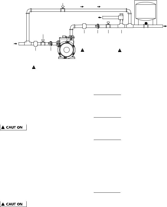
FIG 1 TYPICAL INSTALLATIONS
Ball Valve #3 (Closed)
|
|
By-Pass |
|
Optional |
|
|
|
|
Water |
|
|
Drain |
|
Tank |
|
Ball |
|
Home or Irrigation |
|
|
|
|
||
|
|
|
1" Dia. Discharge |
|
|
Valve |
|
|
|
|
|
|
OUT |
|
|
#1 |
|
|
|
|
|
|
|
|
City Water Main |
(Open) |
|
|
|
|
Adjustable Union |
Ball |
Pressure |
|
only |
|
|||
|
Pressure |
Valve |
Relief |
|
1" Dia. Suction |
|
|||
|
Regulator |
#2 |
Valve |
|
IN |
|
|||
|
(APR) |
(Open) |
(PRV) |
|
|
|
|||
|
Adjustable |
#2 |
|
#3 |
|
Union |
|
|
|
|
Pressure |
|
|
|
|
Regulator |
|
|
IL1213 |
|
(APR) |
|
|
|
|
|
|
|
|
|
#1 |
|
|
|
1/2 HP PERFORMANCE
See charts below for expected system pressure at various incoming line pressure / flow rates.
Inlet |
|
VP05 System Pressure (PSI) |
|
||||||
|
|
at Flow Rates (GPM) |
|
|
|||||
PSI |
|
|
|
|
|||||
3 |
6 |
|
9 |
12 |
15 |
|
18 |
21 |
|
|
|
|
|||||||
10 |
44 |
39 |
|
32 |
25 |
17 |
|
|
|
20 |
54 |
49 |
|
42 |
35 |
27 |
|
|
|
30* |
64 |
59 |
|
52 |
45 |
37 |
|
|
|
 Do not exceed 30 input PSI for P/N VP05
*Note: Increase tank PSI (see Fig 3) if inlet PSI will exceed preset tank setting 26 psi.
1 HP PERFORMANCE
Inlet |
|
VP10 System Pressure (PSI) |
|
||||||
|
|
at Flow Rates (GPM) |
|
|
|||||
PSI |
|
|
|
|
|||||
3 |
6 |
|
9 |
12 |
15 |
|
18 |
21 |
|
|
|
|
|||||||
10 |
66 |
61 |
|
54 |
46 |
37 |
|
29 |
18 |
20 |
76 |
71 |
|
64 |
56 |
47 |
|
39 |
28 |
30 |
86 |
81 |
|
74 |
66 |
57 |
|
49 |
38 |
40** |
96 |
91 |
|
84 |
76 |
67 |
|
59 |
48 |
50** |
106 |
101 |
|
94 |
86 |
77 |
|
69 |
58 |
 Do not exceed 50 input PSI for P/N VP10
**Note: Increase Tank PSI (see Fig 3) if inlet PSI will exceed preset tank setting 36 psi.
GENERAL PUMP INSTALLATION / SETUP (FIG 1)
City booster pump installation is shown per
FIG 1. During pump use, insure ball valves #1 and #2 are open, and ball valve #3 is closed.


 #1 An Adjustable Pressure Regulator (APR#1) is required on the suction side of the pump (see fig 1) if the incoming water pressure can exceed the maximum input pressure.
 #2 An Adjustable Pressure Regulator (APR#2) is required on the Discharge (See fig 1) to insure maximum water pressure does not exceed local plumbing codes.


 #3 A Pressure Relief Valve (PRV) connected to a drain is required (see fig 1) to safe guard plumbing from exceeding max pressures if the Pressure Regulators fail. Typically the PRV would be set 5 psi higher than the APR#2.
NOTE: Optional external water tank can be used to decrease the on/off cycle rate of the pump system, which can extend the life of the pump. (Typical tank 3 gallon draw down.) Set tank PSI equal to pump tank PSI.


 The entire system must be air and water tight to maintain prime. Use thread tape on all connections to insure no leaks. Hand tighten all threads and then add additional half turn with wrench.
3
95 North Oak Street • Kendallville, IN 46755 • © 2014 Flint & Walling, Inc. All rights reserved.
 Loading...