

Page 1
OWNER'S
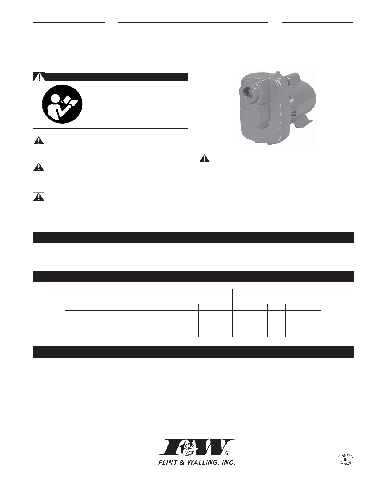
SPM SERIES
FW0501
MANUAL
Lawn and Turf Pumps
Electric Motor Driven
SAFETY WARNINGS
BEFORE OPERATING OR
INSTALLING THIS PUMP, READ
THIS MANUAL AND FOLLOW
ALL SAFETY RULES AND
OPERATING INSTRUCTIONS.
SAFETY
CAUTION
• Review instructions before operating.
WARNING - ELECTRICAL PRECAUTIONS
All wiring, electrical connections, and system grounding must
comply with the National Electrical Code (NEC) and with any local
codes and ordinances. Employ a licensed electrician.
CAREFULLY READ THESE SAFETY
MESSAGES IN THIS MANUAL AND ON PUMP.
WARNING - RISK OF ELECTRICAL SHOCK
• Have an electrician provide electrical power to the motor.
• Motor must be grounded and terminal cover in place to reduce
electrical shock hazard.
• Keep motor operating area as dry as possible.
• A ground fault interrupter (GFI) protected circuit is recommended for use with any electrical device operating near water.
• Always disconnect power before servicing.
• Not investigated for use in swimming pool areas.
APPLICATION
This pump is suitable for installations where the vertical distance
from the pump to the water level does not exceed 25 ft. In all
PERFORMANCE
Flow in GPM Flow in L/min.
PUMP at total head (ft.) at total head (Meters)
MODEL HP 25 50 75 100 125 150 1 0 2 0 3 0 4 0 5 0
SPM30 3 110 92 71 40 371 276 110
SPM50 5 141 121 98 66 560 466 348 148
INSTALLATION
PUMP LOCATION: The pump should be installed in a clean, dry
and ventilated location which provides adequate drainage and
room for servicing and protection from freezing temperatures. It
should be bolted down evenly on a good foundation, preferably
concrete, to prevent the development of unnecessary stress.
Locating the pump as close as possible to the source of water
supply reduces the friction losses in the suction pipe and provides
for maximum capacities.
SUCTION PIPE: It is recommended that only new clean pipe or
installations, friction losses in the suction pipe must be taken into
consideration.
hose be used and the size be the same as that of the pump
suction tapping. If the pump is installed any appreciable distance
away from the source of water supply, the suction pipe should be
increased by one size. The suction pipe must always slope
upwards from the water source to the pump to avoid air pockets
in the line. In cases where the pump has to be reprimed often and
it is not necessary that a lot of water be delivered, it is advisable
to use a 90° or 45° elbow on the suction line. This enables the
pump to prime sooner and also prevents kinking of the hose. In
cases where a maximum volume of water is required over a pro-
236222 0403
Page 2

longed period of time, the suction line should be led almost horizontally to the pump. Non-toxic thread compound should be used on all
pipe joints and connections should be thoroughly tightened. A
strainer should be connected to the bottom end of the suction pipe
and it should be well submerged at all times.
WARNING - RISK OF ELECTRICAL SHOCK
• WIRING: Make sure the voltage and frequency of the power
supply agrees with that stamped on the motor nameplate. If
in doubt, check with the power company.
WARNING - ELECTRICAL PRECAUTIONS
All wiring, electrical connections, and system grounding must
comply with the National Electrical Code (NEC) and with any local
codes and ordinances. Employ a licensed electrician.
SINGLE PHASE: Determine incoming voltage to motor. Where
possible, use 230V. Connect wiring to terminal board located inside
motor end cover. Be sure voltage connections agree with wiring
diagram on motor nameplate.
THREE PHASE: Three Phase motors require magnetic starters,
and can run in either direction, depending on how they are connected to the power supply.
OPERATION - PRIMING THE PUMP
To Check for Proper Rotation: Remove the motor end cover.
This exposes the motor shaft. If hookup is correct, the shaft will
rotate clockwise. If rotation is not clockwise, reverse any two leads
to the starter. The rotation will now be correct.
WARNING - RISK OF ELECTRICAL SHOCK
GROUNDING THE MOTOR: WIRING TO THIS PUMP MUST
BE INSTALLED AND MAINTAINED IN ACCORDANCE WITH
THE NATIONAL ELECTRICAL CODE OR YOUR LOCAL
ELECTRIC CODE. IF MORE INFORMATION IS NEEDED,
CALL YOUR LOCAL LICENSED ELECTRICIAN OR YOUR
POWER COMPANY.
It is recommended that a permanent ground connection be made to
the unit using a conductor of appropriate size from a metal underground water pipe or a grounded lead in the service panel. Do not
ground to a gas supply line. Do not connect to electric power supply
until unit is permanently grounded. Connect the ground wire to the
approved ground and then connect to the terminal provided.
WARNING:
PRIMING THE PUMP: A priming plug is provided in the top of the
casing to fill the pump with water. Once filled and the priming plug
replaced, the pump will prime. The priming time depends upon the
vertical and horizontal distance between the pump and the water
level. The pump should prime itself time after time as long as the
built-in check valve functions.
CAUTION:
PRIMING UNDER PRESSURE: (Refer to Figure 1) Should it be
necessary to prime under pressure, place a check valve on the
discharge line of the pump and a pet cock or a ball type air bleeder
in place of the priming plug, or an air bleed line with a gate valve
connected to the discharge line. It will then be possible for the liquid
to remain in the discharge pipe and allow the pump to bleed off the
remaining air, thereby facilitating priming.
IMPELLER ROTATION: The impeller must rotate in a counterclockwise direction as seen facing the pump from the front of the
casing. In the event of wrong rotation for electric motor models,
refer to the instructions furnished with the motor. The rotation of
three phase motors can be changed by interchanging any two lead
wires.
STARTING THE PUMP: Never operate the pump dry as this may
damage the seal. If an exceptionally long suction line is used, the
water in the pump casing may become overheated or vapour
locked. Should this occur, replace the water in the casing with cold
water and continue priming.
DRAINING: Should the pump be subject to freezing temperatures,
it will be necessary to drain the pump completely. To drain, remove
the drain plug located at the bottom of the front face of the pump
casing and the priming plug and make sure that the drain
DO NOT RUN THE PUMP BEFORE PRIMING IT, SINCE THE SEAL AND IMPELLER COULD BE PERMANENTLY
DAMAGED.
DO NOT run the pump before filling the pump
case with liquid, as it may damage the seal.
hole is not restricted. After all the water has been drained,
operating the pump for a few seconds will ensure that the impeller
is devoid of water (make sure that the suction line is also devoid
of water).
STORAGE OF PUMP: Drain liquid from pump to prevent freezing. It is recommended that a good rust inhibitor be put in the
liquid end to prevent excessive corrosion. Be sure motor is kept
dry and covered. When restoring the use of the pump, replace all
plugs and make sure all connections are tightly sealed. After a
complete check is made, make the initial prime according to
directions under the section, Priming the Pump.
Figure 1
Gate Valve
(Min. 3/4")
2
Check Valve
Gate Valve
Discharge
Pump
Air Bleed Line
Suction Line
Strainer
Page 3
MAINTENANCE
WARNING - ELECTRICAL PRECAUTIONS
All wiring, electrical connections, and system grounding must
comply with the National Electrical Code (NEC) and with any local
codes and ordinances. Employ a licensed electrician.
WARNING - RISK OF ELECTRICAL SHOCK
• Have an electrician provide electrical power to the motor.
• Motor must be grounded and terminal cover in place to reduce
electrical shock hazard.
• Keep motor operating area as dry as possible.
• A ground fault interrupter (GFI) protected circuit is recom-
mended for use with any electrical device operating near water.
• Always disconnect power before servicing.
• Not investigated for use in swimming pool areas.
LUBRICATION:
a) The pump requires no lubrication.
b) For electric motor models, refer to instructions provided
by the motor manufacturer.
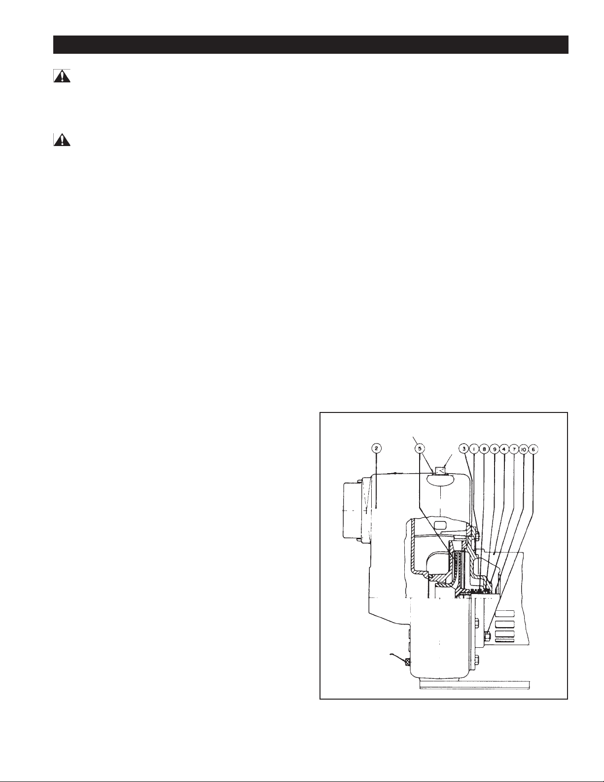
REPLACING MECHANICAL SEAL:
(Refer to Figure 2)
TO DISASSEMBLE:
TO REASSEMBLE:
a) Clean all parts thoroughly.
b) Wet the rubber part of the seal seat with soap solution
and press it into its housing in the seal plate or adapter,
smooth ceramic surface facing outwards.
c) Assemble the seal plate or adapter to the motor.
d) Oil the seal and slip it into the motor shaft. Make sure
the sealing face is towards the ceramic seat.
e) Replace the impeller.
f) Reassemble to the casing and diffuser ring. It is
recommended to use a new gasket (3).
g) Reconnect the suction and discharge piping and re-
connect the electrical wiring.
PRECAUTIONS
a) Whenever pump is dismantled and then reassembled,
always check to see that the impeller rotates freely within
the casing.
b) The SPM models have a flinger (10) on the shaft. This
flinger must not be removed.
a) Remove the bolts (1) and remove the casing (2).
b) Remove the impeller (unscrew impeller or remove retain-
ing bolt depending upon the model).
c) Slip the seal off the shaft.
d) Remove the four bolts and lift the adapter (7) off the motor.
Take care not to damage the seal seat.
e) If the seat (9) needs to be replaced, push it out of the
adapter from the motor side.
Figure 2
Drain Plug
Discharge
Priming
Plug
3
Page 4

TROUBLESHOOTING GUIDE
TROUBLES AND CAUSE REMEDY
Failure to Pump:
1. Pump not properly primed. 1. Make sure pump casing and suction line are full of water.
See priming instructions.
2. Speed too low. 2.
3. Total head more than for which pump was intended. 3. A pump designed for higher head needed.
4. Suction lift is too great. 4. Locate pump closer to source of water. Make sure suction
Reduced Capacity and/or Head:
1. Air pockets or leaks in suction line. 1. Check suction piping.
2. Clogged impeller. 2. Remove and clean.
3. Strainer too small or clogged. 3. Use larger strainer or clean.
4. Insufficient submergence of suction line. 4. Add lengths of suction pipe to keep submerged end well
5. Excessive suction lift. 5. If caused by suction pipe friction, enlarge piping.
6. Total head more than that for which the pump was 6. A pump designed for higher head is needed.
intended.
7. Excessively worn impeller. 7. Order replacement parts using Repair Parts List.
WARNING - ELECTRICAL PRECAUTIONS
All wiring, electrical connections and system grounding
must comply with the National Electrical Code (NEC) and
with any local codes and ordinances. Employ a licensed
electrician. Check voltage at motor terminals and at meter
when pump is operating. If low, refer to wiring instructions
or check with your power company. Check loose connections.
piping is large enough.
below the water surface.
Otherwise, move pump closer to water level.
Pump Loses Prime:
1. Air leaks in suction line. 1. Check suction piping.
2. Excessive lift and operating too near shut-off point. 2. Move pump nearer water level.
3. Water level drops while pumping, uncovering suction 3. Check water supply. Add length of pipe to suction to
piping. keep submerged end under water.
Mechanical Troubles and Noise:
1. Bent shaft and/or damaged bearings. 1. Take motor to authorized motor repair shop.
2. Suction and/or discharge piping not properly 2. See that all piping is supported to relieve strain on pump
supported and anchored. assembly.
WATER SYSTEMS ONE-YEAR LIMITED WARRANTY
This product is warranted for one year from the date of purchase
or two years from the date of manufacture, whichever occurs first.
Subject to the conditions hereinafter set forth, the manufacturer will
repair or replace to the original consumer, any portion of the
product which proves defective due to defective materials or
workmanship. To obtain warranty service, contact the dealer from
whom the product was purchased. The manufacturer retains the
sole right and option to determine whether to repair or replace
defective equipment, parts or components. Damage due to conditions beyond the control of the manufacturer is not covered by this
warranty.
THIS WARRANTY WILL NOT APPLY: (a) To defects or malfunctions
resulting from failure to properly install, operate or maintain the unit
in accordance with printed instructions provided; (b) to failures
resulting from abuse, accident or negligence; (c) to normal maintenance services and the parts used in connection with such service;
(d) to units which are not installed in accordance with normal
applicable local codes, ordinances and good trade practices; and
(e) the unit is used for purposes other than for what it was
designed and manufactured.
RETURN OF WARRANTED COMPONENTS: Any item to be repaired or
replaced under this warranty must be returned to the manufacturer
at Kendallville, Indiana or such other place as the manufacturer may
designate, freight prepaid.
THE WARRANTY PROVIDED HEREIN IS IN LIEU OF ALL OTHER
EXPRESS WARRANTIES, AND MAY NOT BE EXTENDED OR
MODIFIED BY ANYONE. ANY IMPLIED WARRANTIES SHALL BE
LIMITED TO THE PERIOD OF THE LIMITED WARRANTY AND
THEREAFTER ALL SUCH IMPLIED WARRANTIES ARE DISCLAIMED
AND EXCLUDED. THE MANUFACTURER SHALL NOT, UNDER ANY
CIRCUMSTANCES, BE LIABLE FOR INCIDENTAL, CONSEQUENTIAL
OR SPECIAL DAMAGES, SUCH AS, BUT NOT LIMITED TO DAMAGE
TO, OR LOSS OF, OTHER PROPERTY OR EQUIPMENT, LOSS OF
PROFITS, INCONVENIENCE , OR OTHER INCIDENTAL OR
CONSEQUENTIAL DAMAGES OF ANY TYPE OR NATURE. THE
LIABILITY OF THE MANUFACTURER SHALL NOT EXCEED THE PRICE
OF THE PRODUCT UPON WHICH SUCH LIABILITY IS BASED.
This warranty gives you specific legal rights, and you may have
other rights which vary from state to state. Some states do not
allow limitations on duration of implied warranties or exclusion of
incidental or consequential damages, so the above limitations may
not apply to you.
FOR YOUR WARRANTY PROTECTION, THE WARRANTY REGISTRATION MUST BE COMPLETED AND RETURNED TO THE WARRANTY INFORMATION CENTER WITHIN TEN DAYS OF INSTALLATION. WARRANTY VALID IN CANADA AND MEXICO.
95 North Oak Street • Kendallville, IN 46755 • 800-345-9422
Flint and Walling reserves the right to make design improvements and
pricing modifications as necessary and without notice.
Page 5

MANUEL DU
SÉRIE SPM
FW0501F
PROPRIÉTAIRE
Pompe pour Gazon et Pelouse
Actionnée par Moteur Électrique
CONSIGNES DE SÉCURITÉ
AVANT D'INSTALLER OU
D'UTILISER CETTE POMPE,
PRIÈRE DE LIRE LE PRÉSENT
GUIDE ET SUIVRE TOUTES
LES RÈGLES DE SÉCURITÉ ET
INSTRUCTIONS D'UTILISATION.
SÉCURITÉ
CAUTION
• Passez les instructions en revue avant d’utiliser la pompe.
MISE EN GARDE
- PRÉCAUTIONS ÉLECTRIQUES
Tous câblage, connexions électriques et mise à la terre des
systémes doivent se conformer au Code National d'Electricité
(NEC) et aux codes et ordonnances locaux. Employez un
électricien autorisé.
LIRE ATTENTIVEMENT LES AVIS DE
SÉCURITÉ SE TROUVANT DANS LE
PRÉSENT MANUEL ET SUR LA POMPE.
MISE EN GARDE
- RISQUE DE CHOC ÉLECTRIQUE
• Faire appel à un électricien pour l’alimentation électrique du
moteur.
• Le moteur doit être mis à la terre et le couvercle des bornes
correctement installé afin de réduire les risques
d’électrocution.
• Garder la zone de travail aussi sèche que possible.
• L’usage d’un circuit protégé par interrupteur de défaut à la terre
(GFI) est recommandé avec tout appareil électrique
fonctionnant dans l’eau ou à proximité de celle-ci.
• Toujours couper l’alimentation avant de procéder à l’entretien.
• Cette pompe n’est pas conçue pour être utilisée dans la région
d'une piscine.
UTILISATION
Cette pompe convient aux installations dont la distance verticale
entre la pompe et l’eau à pomper ne dépasse pas 25 pieds. Dans
RENDEMENT
Débit en GPM (US) Débit en L/min.
Modèle de Hauteur totale (pi) Hauteur totale (mètres)
pompe CV 25 50 75 100 125 150 10 20 30 40 50
SPM30 3 110 92 71 40 371 276 110
SPM50 5 141 121 98 66 560 466 348 148
INSTALLATION
EMPLACEMENT DE LA POMPE : Il est conseillé d’installer la
pompe dans un endroit propre, sec et aéré offrant un bon
drainage, de l’espace pour l’entretien et une protection contre le
gel. Il faudrait la boulonner bien à plat à une assise solide, de
préférence en béton, afin de prévenir les contraintes inutiles.
Pour réduire les pertes de charge dans la conduite d’aspiration
et obtenir le débit maximal, rapprocher le plus possible la pompe
de l’eau à pomper.
CONDUITE D’ASPIRATION : Il est recommandé d’utiliser un
tuyau ou un boyau neuf et propre dont le diamètre est égal au
tous les cas, il faut tenir compte des pertes de charge dans la
conduite d’aspiration.
taraudage de l’orifice d’aspiration. Si la pompe se trouve à une
distance assez importante de la source d’alimentation en eau, le
diamètre de la conduite d’aspiration devrait être plus grand. La
conduite d’aspiration doit toujours être placée en pente
ascendante à partir de la source d’eau vers la pompe, pour éviter
la formation de poches d’air dans la conduite. Dans les cas où la
pompe doit être réamorcée souvent et qu’un grand débit d’eau
n’est pas nécessaire, il est conseillé d’utiliser un coude de 90° ou
de 45° dans la conduite d’aspiration. L’amorçage peut ainsi se
faire plus rapidement et prévenir le tortillement du boyau. Si un
volume d’eau important est requis pendant une période
prolongée
236222f 0403
Page 6

prolongée, la conduite d’aspiration devrait être aussi à l’horizontale
que possible par rapport à la pompe. Il est également conseillé
d’enduire les joints et les raccords de tuyau, d’une graisse pour
filetage non toxique et de bien les serrer. L’extrémité inférieure de la
conduite d’aspiration devrait être munie d’une crépine immergée en
tout temps.
AVERTISSEMENT
- RISQUE DE CHOC ÉLECTRIQUE
• CÂBLAGE : S’assurer que le voltage et la fréquence de
l’alimentation en électricité sont conformes aux instructions se
trouvant sur la plaque du fabricant du moteur. Dans le doute,
vérifier auprès de votre compagnie d’électricité.
AVERTISSEMENT
- PRÉCAUTIONS RELATIVES À L’ÉLECTRICITÉ
Le câblage, les connexions électriques et les mises à la terre des
systèmes doivent être conformes au Code national de l’électricité
(NEC) et aux ordonnances et codes locaux. Faire appel à un
électricien autorisé.
MOTEUR MONOPHASÉ : Établir d’abord le voltage d’entrée au
moteur. Si la chose est possible, utiliser un courant de 230V.
Brancher le câblage au panneau de raccordement situé sous le
couvercle du moteur. S’assurer que les raccords de voltage sont
les mêmes que ceux du schéma de montage figurant sur la plaque
du fabricant du moteur.
Pour déterminer si le moteur tourne dans le bon sens, enlever
le couvercle du moteur. L’arbre moteur est maintenant exposé. Si
le branchement du moteur est bien effectué, l’arbre tournera dans
le sens des aiguilles d’une montre. Si la rotation de l’arbre est dans
le sens contraire des aiguilles d’une montre, inverser deux des
conducteurs de branchement du démarreur. Le moteur tournera
alors dans le bon sens.
AVERTISSEMENT
- RISQUE DE CHOC ÉLECTRIQUE
MISE À LA TERRE DU MOTEUR : LE CÂBLAGE DE CETTE
POMPE DOIT ÊTRE INSTALLÉ ET ENTRETENU
CONFORMÉMENT AU CODE NATIONAL DE L’ÉLECTRICITÉ
OU AUX ORDONNANCES ET CODES D’ÉLECTRICITÉ
LOCAUX. POUR DE PLUS AMPLES RENSEIGNEMENTS,
CONSULTEZ UN ÉLECTRICIEN AUTORISÉ OU VOTRE
PROPRE COMPAGNIE D’ÉLECTRICITÉ.
Il est recommandé de munir l’unité d’une prise à la terre
permanente, au moyen d’un conducteur de dimension appropriée,
fixé à une conduite d’eau souterraine ou une conduite avec mise à
la terre dans le panneau de service. Éviter de brancher l’unité à une
source d’alimentation en gaz avant qu’elle soit correctement mise
à la terre. Brancher le fil de masse à la mise à la terre approuvée,
puis raccorder le fil à la borne accompagnant la pompe.
MOTEUR TRIPHASÉ : Un moteur triphasé doit être muni d’un
démarreur magnétique. La rotation de ce genre de moteur peut se
faire dans les deux sens, selon le branchement de l’alimentation
électrique.
FONCTIONNNEMENT - AMORÇAGE DE LA POMPE
AVERTISSEMENT :
AMORÇAGE DE LA POMPE : Pour amorcer la pompe, il faut
enlever le bouchon d’amorçage se trouvant sur le dessus du boîtier,
remplir le boîtier d’eau et remettre le bouchon en place. La durée
d’amorçage est fonction de la distance horizontale et verticale entre
la pompe et le niveau de l’eau. La pompe devrait s’amorcer
automatiquement à chaque utilisation, tant que le clapet de retenue
intégré fonctionne.
AVERTISSEMENT : NE JAMAIS faire démarrer la pompe à
AMORÇAGE SOUS PRESSION : (Voir figure 1). S’il faut amorcer
la pompe sous pression, placer un clapet de retenue sur la conduite
de refoulement de la pompe et remplacer le bouchon d’amorçage
par un robinet de purge d’air ordinaire ou sphérique , ou installer une
conduite du purgeur d’air et un robinet-vanne sur la conduite de
refoulement. Le liquide pourra alors demeurer dans la conduite de
refoulement et l’action du robinet-vanne facilitera l’amorçage de la
pompe.
DE NE PAS FAIRE FONCTIONNER LA POMPE À SEC AVANT L’AMORÇAGE, SINON LE JOINT D’ÉTANCHÉITÉ
ET LA ROUE DE TURBINE SERAIENT ENDOMMAGÉS DE FAÇON PERMANENTE.
sec, car la garniture d’étanchéité
pourrait s’endommager.
Figure 1
Robinet-vanne
(Min. 3/4")
Clapet de retenue
Robinet-vanne
Refoulement
Pompe
Conduite de
purgeur d'air
Tuyauterie
d'aspiration
Crépine
ROTATION DE LA ROUE DE TURBINE : Vue de face, devant le
boîtier, la rotation devrait se faire dans le sens contraire des aiguilles
d’une montre. Si la rotation d’une pompe actionnée par un moteur
électrique ne s’effectue pas dans le bon sens, consulter le mode
d’emploi du moteur. Il est possible de modifier le sens de rotation
d’un moteur triphasé en inversant deux fils conducteurs.
2
Page 7

MISE EN MARCHE : Ne jamais faire fonctionner la pompe à sec,
car la garniture d’étanchéité pourrait s’endommager. Si la
conduite d’aspiration est très longue, l’eau contenue dans le
boîtier peut surchauffer ou produire une cavitation. Le cas
échéant, remplacer l’eau du boîtier par de l’eau froide et
continuer l’amorçage.
VIDANGE : Si la pompe est exposée au gel, il faudra la vidanger
complètement. Pour ce faire, enlever le bouchon de vidange
situé dans la partie inférieure du devant du boîtier ainsi que le
bouchon d’amorçage et s’assurer que l’orifice de vidange n’est
pas obstrué. Dès que toute l’eau est évacuée, faire fonctionner la
pompe pendant quelques secondes pour éliminer toute eau
ENTRETIEN
MISE EN GARDE
- PRÉCAUTIONS ÉLECTRIQUES
Tous câblage, connexions électriques et mise à la terre des
systémes doivent se conformer au Code National d'Electricité
(NEC) et aux codes et ordonnances locaux. Employez un
électricien autorisé.
MISE EN GARDE
- RISQUE DE CHOC ÉLECTRIQUE
• Faire appel à un électricien pour l’alimentation électrique du
moteur.
• Le moteur doit être mis à la terre et le couvercle des bornes
correctement installé afin de réduire les risques
d’électrocution.
• Garder la zone de travail aussi sèche que possible.
• L’usage d’un circuit protégé par interrupteur de défaut à la terre
(GFI) est recommandé avec tout appareil électrique
fonctionnant dans l’eau ou à proximité de celle-ci.
• Toujours couper l’alimentation avant de procéder à l’entretien.
• Cette pompe n’est pas conçue pour être utilisée dans la région
d'une piscine.
LUBRIFICATION :
a) Cette pompe n’exige aucune lubrification.
b) Pour la lubrification du moteur électrique, consulter le
mode d’emploi du fabricant.
subsistante dans la roue (veiller également à l’évacuation de
toute eau dans la conduite d’aspiration).
ENTREPOSAGE DE LA POMPE : Évacuer tout le liquide
contenu dans la pompe afin de prévenir les bris causés par le gel.
Il est recommandé d’appliquer un bon agent antirouille dans le
boîtier afin d’empêcher la formation excessive de corrosion.
S’assurer que le moteur est toujours au sec et couvert. Au
moment de remettre la pompe en marche, remplacer tous les
bouchons et vérifier l’étanchéité parfaite de tous les
raccordements. Après une vérification complète, amorcer la
pompe en suivant les directives de la rubrique Amorçage.
REMONTAGE :
a) Bien nettoyer toutes les pièces.
b) Mouiller la partie en caoutchouc de l’embase de la
garniture d’étanchéité mécanique avec une eau
savonneuse et remettre la pièce dans son logement,
dans la plaque d’étanchéité ou l’adaptateur, la surface
de céramique donnant vers l’extérieur.
c) Remonter la plaque d’étanchéité ou l’adaptateur sur le
moteur.
d) Huiler la garniture d’étanchéité mécanique et le faire
glisser sur l’arbre moteur. Bien s’assurer que la surface d’étanchéité donne vers l’embase de céramique.
e) Revisser la roue de turbine.
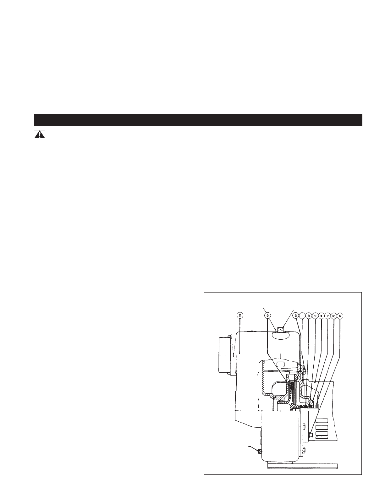
f) Remonter le tout dans le boîtier et remettre en place
l’anneau de retenue du diffuseur. Il est conseillé d’installer
un nouveau joint d’étanchéité (3).
g) Raccorder les canalisations d’aspiration et de
refoulement et brancher de nouveau les fils électriques.
PRÉCAUTIONS
a) Au moment de démonter et de remonter la pompe, il
faut toujours vérifier si la roue tourne librement dans le
boîtier.
b) L’arbre des pompes de la série SPM est muni d’une
bride (10) qu’il ne faut jamais enlever.
REMPLACEMENT DE LA GARNITURE
D’ÉTANCHÉITÉ MÉCANIQUE : Voir la figure 2
DÉMONTAGE :
a) Dévisser les boulons (1) et retirer le boîtier (2).
b) Enlever la roue (en la dévissant ou en enlevant le boulon
de retenue, selon le modèle).
c) Faire glisser la garniture d'étanchéité mécanique hors de
l'arbre.
d) Enlever les quatre boulons et soulever l'adaptateur (7)
pour le séparer du moteur. Prendre bien soin de ne pas
endommager l'embase de la garniture d'étanchéité.
e) S'il faut remplacer l'embase (9), l'extraire de l'adaptateur
du côté du moteur.
Figure 2
3
Bouchon de
vidange
Refoulement
Bouchon d'amorçage
Page 8

GUIDE DE DÉPANNAGE
PROBLÈMES ET CAUSES PROBABLES SOLUTIONS
Aucun pompage :
1. La pompe n’est bien amorcée. 1. S’assurer que le boîtier et la conduite d’aspiration sont remplis d’eau.
2. Le régime est trop faible. 2.
3. La hauteur totale requise ne correspond pas aux 3. Pompe conçue pour une hauteur totale plus élevée.
caractéristiques de la pompe.
4. La hauteur géométrique d’aspiration est trop élevée. 4. Rapprocher la pompe de la source d’alimentation en eau. S’assurer
Perte de débit et (ou) de charge :
1. Fuites ou poches d’air dans la conduite d’aspiration. 1. Inspecter les canalisations d’aspiration.
2. Obstruction de la roue de turbine. 2. Retirer et nettoyer la roue de turbine.
3. Crépine trop petite ou obstruée. 3. Installer une plus grande crépine ou nettoyer celle en place.
4. La conduite d’aspiration n’est pas bien immergée. 4. Rajouter des sections à la conduite d’aspiration afin d’en maintenir
5. La hauteur géométrique d’aspiration est trop élevée. 5. Si le problème est causé par un frottement à l’intérieur de la conduite
6. La hauteur totale ne correspond pas aux 6. Il faut installer une pompe dont la hauteur totale est plus élevée.
caractéristiques de la pompe.
7. La roue est trop usée. 7. Commander une nouvelle pièce. Consulter la liste des pièces de
Perte d’amorçage :
1. Fuites d’air dans la conduite d’aspiration. 1. Inspecter les canalisations d’aspiration.
2. Hauteur géométrique d’aspiration trop élevée et trop rapprochée 2. Rapprocher la pompe du niveau de l’eau.
de la pression à débit nul.
3. Le niveau d’eau baisse pendant le pompage et met la conduite 3. Vérifier la source d’eau. Rajouter une section à la conduite d’aspiration
d’aspiration à l’air libre. afin d’en maintenir l’extrémité dans l’eau.
Suivre les directives d’amorçage.
AVERTISSEMENT
-PRÉCAUTIONS RELATIVES À L’ÉLECTRICITÉ
Le câblage, les connexions électriques et les mises à la terre des
systèmes doivent être conformes au Code national de l’électricité (NEC)
et aux ordonnances et codes locaux. Consulter un électricien autorisé.
Vérifier le voltage aux bornes du moteur et le voltmètre pendant le
pompage. Si le voltage est trop faible, consulter les directives de
montage électrique ou communiquer avec votre compagnie
d’électricité. S’assurer que tous les raccords sont bien serrés.
que les conduites d’aspiration sont de dimension adéquate.
l’extrémité bien immergée.
d’aspiration, accroître le diamètre des canalisations. Sinon, rapprocher
la pompe de l’eau à pomper.
rechange.
Problèmes mécaniques et bruits :
1. Arbre voilé ou paliers endommagés ou les deux. 1. Faire vérifier le moteur dans un atelier de réparation reconnu.
2. Les canalisations d’aspiration ou de refoulement ne 2. S’assurer que toutes les canalisations sont bien assujetties et
sont pas bien soutenues ou assujetties. n’exercent aucune contrainte sur l’installation de la pompe.
WATER SYSTEMS - GARANTIE LIMITÉE D’UN AN
Ce produit porte un garantie d’un an à compter de la date d’achat ou
de deux ans à compter de la date de fabrication, selon la période qui
se termine la première. Sous réserve des conditions exposées ciaprès, le fabricant s’engage à réparer ou à remplacer sans frais
pour le client initial, toute partie du produit qui s’avère comporter des
défauts de matériaux ou de fabrication. Pour vous prévaloir de la
garantie, le cas échéant, communiquez avec votre revendeur de
pompe. Le fabricant se réserve exclusivement le droit de déterminer
s’il doit réparer ou remplacer l’appareil, les pièces ou les éléments.
Cette garantie ne couvre pas les dommages dont la cause est
indépendante de sa volonté.
LA GARANTIE NE S’APPLIQUE PAS DANS LES CAS SUIVANTS: (a)
Défauts ou anomalies de fonctionnement entraînées par la nonconformité de l’installation, de l’utilisation ou de l’entretien du produit
avec les instructions écrites fournies. (b) Défaillances causées par
l’usage abusif, par un accident ou par la négligence. (c) Entretien
normal et pièces nécessaires pour assurer cet entretien. (d)
Installation du matériel ne respectant pas les exigences des codes
et réglementation pertinents en vigueur ou non effectuée dans les
règles de l’art. (e) Utilisation du produit dans des applications pour
lesquelles il n’a pas été conçu ou fabriqué.
RETOUR DES ÉLÉMENTS GARANTIS: Tout article à réparer ou à
remplacer en vertu de la présente garantie doit être expédié au
fabricant, port payé, à Kendallville, Indiana, ou en un autre endroit
que le fabricant peut désigner.
LA GARANTIE FOURNIE EN VERTU DES PRÉSENTES REMPLACE
TOUTE AUTRE GARANTIE EXPRESSE, ET NUL NE PEUT L’ÉTENDRE
OU LA MODIFIER. TOUTE GARANTIE IMPLICITE SE LIMITE À LA
PÉRIODE DE LA GARANTIE LIMITÉE, APRÉS LAQUELLE TOUTES
TELLES GARANTIES IMPLICITES SONT NULLES ET NON AVENUES.
LE FABRICANT NE POURRA EN AUCUN CAS ÊTRE TENU
RESPONSABLE DE DOMMAGES-INTÉRÊTS DIRECTS, INDIRECTS OU
SPÉCIAUX TELS, SANS S’Y LIMITER, ENDOMMAGEMENT OU PERTE
D’AUTRES BIENS OU MATÉRIELS, PERTES DE PROFITS, PRÉJUDICES
OU AUTRES DOMMAGES-INTÉRÊTS DIRECTS OU INDIRECTS DE
TOUT ORDRE ET DE TOUTE NATURE. LA RESPONSABILITÉ. du
fabricant ne pourra dépasser le prix payé pour le produit qui est à
l’origine de cette responsabilité.
La présente garantie confère certains droits particuliers. Vous
pouvez avoir d’autres droits en vertu de la loi, que varie d’une
province et d’un état à l’autre. Il est possible que les lois en vigueur
dans votre région interdisent la limitation de la durée des garanties
implicites ou l’exclusion de dommages-intérêts directs ou indirects,
auquel cas les restrictions ci-dessus ne s’appliquent pas.
POUR VALIDER LA PROTECTION ASSURÉE PAR LA GARANTIE,
VOUS DEVEZ REMPLIR LA CARTE DE GARANTIE ET LA FAIRE
PARVENIR AU FABRICANT DANS DANS LES DIX JOURS SUIVANT
LA DATE D’INSTALATION
95 North Oak Street • Kendallville, IN 46755 • 800-345-9422
Flint and Walling se réserve le droit d'améliorer la conception
et de modifier les prix au besoin, sans avis préalable.
Page 9

MANUAL DEL
SERIE SPM
FW0501S
PROPIETARIO
Bombas Para Jardín y Césped
Con Motor Eléctrico
ADVERTENCIAS DE SEGURIDAD
LEA ESTE MANUAL Y SIGA
TODAS LAS REGLAS DE
SEGURIDAD ANTES DE
INSTALAR U OPERAR ESTA
BOMBA.
SEGURIDAD
CUIDADO
• Revise cuidadosamente las instrucciones antes de usarla.
ADVERTENCIA
- PRECAUCIONES ELÉCTRICAS
Todo cableado, conexiones eléctricas y sistemas de contacto a
tierra deben cumplir con el Código Eléctrico Nacional (NEC) y con
cualquier código y ordenanza local. Contrate los servicios de un
electricista con licencia.
LEA CUIDADOSAMENTE ESTOS
MENSAJES DE SEGURIDAD EN ESTE
MANUAL Y EN LA BOMBA.
ADVERTENCIA
- RIESGO DE DESCARGA ELÉCTRICA
• Haga que un electricista le conecte la electricidad al motor.
• El motor debe estar conectado a tierra y la tapa del terminal
debe estar puesta para reducir el peligro de descarga
eléctrica.
• Mantenga el área de operación del motor lo más seca posible.
• Se recomienda se use un circuito protegido por un interruptor
por contacto a tierra (GFI) con cualquier aparato eléctrico que
opere cerca del agua.
• Desconecte siempre el suministro eléctrico antes de darle
servicio.
• No se ha investigado su uso para el área de piscinas.
APLICACIÓN
Utilice estas bombas para aplicaciones donde la distancia
vertical desde la bomba hasta el nivel del agua no sea mayor de
RENDIMIENTO
Flujo en GPM en Flujo en Litros por Minuto
Modelo de presión total (pies) en presión total (Metros)
bomba CV 25 50 75 100 125 150 10 20 30 40 50
SPM30 3 110 92 71 40 371 276 110
SPM50 5 141 121 98 66 560 466 348 148
INSTALACIÓN
UBICACIÓN DE LA BOMBA: Instale la bomba en un lugar
limpio, seco y ventilado, con drenaje adecuado, suficiente
espacio para darle servicio y protegido contra temperaturas
congelantes. Se le debe empernar niveladamente a unos
buenos cimientos, de preferencia de concreto, para evitar
cualquier tensión innecesaria. El ubicar la bomba lo más cerca
posible de la fuente de agua reducirá las pérdidas por fricción en
la tubería de succión y proporcionará las capacidades máximas.
TUBERÍA DE SUCCIÓN: Se recomienda se utilice solamente
25 pies. En todas las instalaciones se debe tomar en
consideración la pérdida por fricción en las tuberías de succión.
tuberías o mangueras nuevas y limpias y del mismo tamaño que
la toma de succión de la bomba. Si la bomba está lejos de la
fuente de agua, la tubería de succión se debe aumentar un
tamaño. Incline la tubería de succión siempre hacia arriba para
evitar bolsas de aire en la misma. En casos en los que se tenga
que cargar la bomba frecuentemente y donde no se necesite
bombear grandes cantidades de agua, se recomienda se use un
codo de 90° o 45° en la línea de succión. Esto le permite a la
bomba cargarse más rápidamente y también evita que la
manguera se pliegue. En los casos en que se necesite un
dddddd
236222s 0403
Page 10

volumen máximo de agua por largos períodos de tiempo, la línea de
succión debe estar casi horizontal con la bomba. Utilice un sellador
no tóxico para rosca en todas las uniones de las tuberías, y las
conexiones deben estar bien ajustadas. Se debe conectar un filtro
o colador en el extremo inferior de la tubería de succión y éste debe
estar bien sumergido en todo momento.
ADVERTENCIA
- PELIGRO DE DESCARGA ELÉCTRICA
• CABLEADO: Asegúrese que el voltaje y la frecuencia del
suministro eléctrico concuerde con los indicados en la placa
de marca del motor. Si tiene dudas, comuníquese con la
compañía eléctrica.
ADVERTENCIA
- PRECAUCIONES ELÉCTRICAS
Todo el cableado, las conexiones eléctricas y los sistemas de
contacto a tierra deben cumplir con el Código Eléctrico Nacional
(NEC) y con todas las ordenanzas y códigos locales. Contrate a un
electricista calificado.
MONOFÁSICOS: Determine cuál es el voltaje de entrada al motor.
Utilice 230V cuando sea posible. Conecte el cableado al tablero del
terminal ubicado dentro de la tapa del motor. Asegúrese que las
conexiones de voltaje concuerden con el diagrama de cableado en
la placa de marca del motor.
Para verificar la rotación correcta: Quite la tapa del motor,
dejando expuesto el eje del motor. Si la conexión es correcta, el eje
girará en el mismo sentido que las manecillas del reloj. Si la
rotación es al contrario, intercambie cualquiera de dos cables que
van al arrancador. La rotación estará ahora corregida.
ADVERTENCIA
- PELIGRO DE DESCARGA ELÉCTRICA
CÓMO CONECTAR EL MOTOR A TIERRA: EL CABLEADO A
ESTA BOMBA DEBE SER INSTALADO Y MANTENIDO DE
ACUERDO AL CÓDIGO ELÉCTRICO NACIONAL O A SU CÓDIGO LOCAL. SI NECESITA MAYOR INFORMACIÓN, LLAME
A SU ELECTRICISTA AUTORIZADO LOCAL O A SU COMPAÑÍA ELÉCTRICA.
Se recomienda se haga una conexión a tierra permanente para la
unidad, utilizando un conductor del tamaño adecuado desde una
tubería metálica subterránea de agua o un conductor conectado a
tierra en el panel de servicio. No la conecte a tierra con una tubería
de suministro de gas. No la conecte al suministro eléctrico hasta
que la unidad esté conectada a tierra permanentemente. Conecte
el cable de contacto a tierra con un contacto a tierra aprobado y
luego conéctela al terminal provisto.
TRIFÁSICOS: Los motores trifásicos requieren arrancadores
magnéticos y pueden funcionar en cualquier dirección, dependiendo de cómo estén conectados al suministro eléctrico.
FUNCIONAMIENTO - CÓMO CARGAR LA BOMBA
AVISO
CÓMO CARGAR LA BOMBA: La bomba tiene un tapón de
cargado ubicado en la parte superior del cuerpo de la bomba para
llenarlo con agua. Una vez llenada y después que vuelva a colocar
el tapón de cargado, la bomba se cargará. El tiempo de cargado
depende de las distancias verticales y horizontales entre la bomba
y el nivel de agua. La bomba se debe cargar sola una y otra vez
mientras que la válvula de chequeo incorporada funcione.
CUIDADO: NO haga funcionar la bomba antes de llenar
CARGADO BAJO PRESIÓN: (Vea la Fig. 1). Si fuera necesario
cargar la bomba bajo presión, instale una válvula de chequeo en la
línea de descarga de la bomba y un grifo de descompresión o un
purgador de aire del tipo de bola en lugar del tapón de cargado, o una
línea de purgado de aire con una válvula de compuerta conectada
a la línea de descarga. Esto permitirá que el líquido se quede en la
tubería de descarga y que la bomba purgue el aire que quede,
facilitando así el cargado.
: NO OPERAR LA BOMBA ANTES DE CARGARLA, EL SELLO Y EL PROPULSOR PODRÍAN DAÑARSE PERMANENTEMENTE.
el cuerpo de la misma con agua, ya que puede
dañar el sello.
Figura 1
Válvula de Compuerta
(Min. 3/4")
Válvula de chequeo
Válvula de
Compuerta
Descarga
Bomba
Línea de purgado de aire
Línea de succión
Colador
ROTACIÓN DEL PROPULSOR: El propulsor debe girar en
sentido contrario a las manecillas del reloj cuando se ve la bomba
desde el frente del cuerpo de la misma. Si el propulsor rotara en
sentido contrario en los modelos con motores eléctricos, vea las
instrucciones proporcionadas con el motor. La rotación de los
motores trifásicos se puede invertir intercambiando cualquiera de
dos cables.
2
Page 11
CÓMO PRENDER LA BOMBA: Nunca haga funcionar la bomba
en seco, ya que podría dañar el sello. Si se usa una línea de
succión excepcionalmente larga, el agua en el cuerpo de la
bomba se puede recalentar y la línea de succión se puede
bloquear con el vapor. Si esto ocurre, reemplace el agua en el
cuerpo de la bomba con agua fría y continúe el cargado.
DRENAJE: Si la bomba va a estar expuesta a temperaturas
congelantes, será necesario drenar la bomba completamente.
Para hacer esto, quite el tapón de drenaje ubicado en la parte
inferior frontal del cuerpo de la bomba, y el de cargado, y
asegúrese que el agujero de drenaje no esté bloqueado. Una vez
que se haya drenado toda el agua, haga funcionar la bomba por
MANTENIMIENTO
unos segundos para sacar todo el líquido del propulsor
(asegúrese que la línea de succión también esté sin agua).
ALMACENAMIENTO DE LA BOMBA: Drene el líquido de la
bomba para evitar el congelamiento del mismo. Se recomienda
se use un buen antioxidante en el líquido para evitar la corrosión
excesiva. Asegúrese que el motor se mantenga seco y cubierto.
Cuando vuelva a usar la bomba, vuelva a colocar todos los
tapones y asegúrese que todas las conexiones estén bien
ajustadas y selladas. Luego de una revisión completa, haga el
cargado inicial de acuerdo a las instrucciones bajo la sección
Cómo Cargar la Bomba.
ADVERTENCIA
- PRECAUCIONES ELÉCTRICAS
Todo el cableado, las conexiones eléctricas y los sistemas de
contacto a tierra deben cumplir con el Código Eléctrico Nacional
(NEC) y con todas las ordenanzas y códigos locales. Contrate a un
electricista calificado.
ADVERTENCIA
- RIESGO DE DESCARGA ELÉCTRICA
• Haga que un electricista le conecte la electricidad al motor.
• El motor debe estar conectado a tierra y la tapa del terminal
debe estar puesta para reducir el peligro de descarga
eléctrica.
• Mantenga el área de operación del motor lo más seca posible.
• Se recomienda se use un circuito protegido por un interruptor
por contacto a tierra (GFI) con cualquier aparato eléctrico que
opere cerca del agua.
• Desconecte siempre el suministro eléctrico antes de darle
servicio.
• No se ha investigado su uso para el área de piscinas.
LUBRICACIÓN:
a) La bomba no necesita lubricación.
b) Para los modelos de motores eléctricos, vea las
instrucciones proporcionadas por el fabricante del motor.
CÓMO REEMPLAZAR EL SELLO MECÁNICO:
(Vea la Fig. 2)
CÓMO DESARMARLA:
CÓMO VOLVERLA A ENSAMBLAR:
a) Limpie completamente todas las piezas.
b) Moje la parte de goma del asiento sellador con una
solución jabonosa y presiónelo dentro de su caja en la
plancha selladora o en el adaptador, con el lado liso de
cerámica hacia el exterior.
c) Ensamble la plancha selladora o el adaptador al motor
eléctrico.
d) Aceite el sello y deslícelo sobre el eje. Asegúrese que
el lado sellador esté hacia el asiento de cerámica.
e) Vuelva a colocar el propulsor.
f) Vuelva a ensamblarlo al cuerpo de la bomba y al anillo
difusor. Se recomienda se use una nueva junta (3).
g) Vuelva a conectar las tuberías de succión y descarga
y vuelva a conectar el cableado eléctrico.
PRECAUCIONES
a) Cuando la desensamble y vuelva a ensamblar,
asegúrese siempre que el propulsor gire libremente
dentro del cuerpo de la bomba.
b) Los modelos SPM tienen un anillo de goma (10) en el
eje. Este anillo de goma no se debe quitar.
Figura 2
Descarga
Tapón de cargado
a) Quite los pernos (1) y el cuerpo de la bomba (2).
b) Quite el propulsor (destornille el propulsor o quite el perno
de retención, dependiendo del modelo).
c) Deslice el sello fuera del eje.
d) Quite los cuatro pernos y levante el adaptador (7) fuera del
motor. Tenga cuidado de no dañar el asiento sellador.
e) Si tiene que reemplazar el asiento (9), presiónelo fuera del
adaptador desde el lado del motor.
Tapón de
descarga
3
Page 12

GUÍA PARA SOLUCIONAR PROBLEMAS
PROBLEMAS Y SUS CAUSAS SOLUCIONES
No bombea:
1. La bomba no está cargada correctamente. 1. Asegúrese que el cuerpo de la bomba y la línea de succión estén
llenas de agua. Vea las instrucciones de cargado.
2. La velocidad es muy lenta. 2.
ADVERTENCIA - PRECAUCIONES ELÉCTRICAS
Todo el cableado, las conexiones eléctricas y los sistemas de contacto
a tierra deben cumplir con el Código Eléctrico Nacional (NEC) y con
todas las ordenanzas y códigos locales. Contrate a un electricista
calificado. Revise el voltaje en los terminales del motor y en el medidor
cuando la bomba esté funcionando. Si está bajo, vea las instrucciones
de cableado o consulte con su compañía eléctrica. Asegúrese que no
haya conexiones flojas.
3. La presión total es mayor para la que la bomba se diseñó. 3. Se necesita una bomba diseñada para mayor presión.
4. La altura de succión es demasiada. 4. Coloque la bomba más cerca de la fuente de agua. Asegúrese
que la tubería de succión es lo suficientemente grande.
Capacidad y/o presión reducidas:
1. Fugas o bolsas de aire en la línea de succión. 1. Revise la tubería de succión.
2. Propulsor atorado. 2. Sáquelo y límpielo.
3. El colador es muy pequeño o está atorado. 3. Utilice un colador más grande o limpio.
4. La línea de succión no está suficientemente sumergida. 4. Añada tramos a la tubería de succión para mantenerla sumergida y bien
por debajo del nivel del agua.
5. La altura de succión es demasiada. 5. Si es causada por la fricción de la tubería de succión, use una tubería
más grande. Caso contrario, coloque la bomba más cerca al nivel de
agua.
6. La presión total es mayor para la que la bomba se diseñó. 6. Se necesita una bomba diseñada para mayor presión.
7. El propulsor está excesivamente gastado. 7. Pida las piezas de repuesto usando la Lista de Piezas de Repuesto.
La bomba pierde la carga:
1. Fuga de aire en la línea de succión. 1. Revise la tubería de succión.
2. La altura de succión es excesiva y está funcionando muy 2. Coloque la bomba más cerca al nivel de agua.
cerca del punto de apague.
3. El nivel del agua baja cuando se bombea, dejando la 3. Revise el suministro de agua. Añada tramos a la tubería de succión
tubería de succión al descubierto. para mantenerla sumergida y bien por debajo del nivel del agua.
Problemas y ruidos mecánicos:
1. Eje doblado y/o rodamientos dañados. 1. Lleve el motor a una tienda autorizada de reparaciones.
2. Las tuberías de succión y/o descarga no están debidamente 2. Asegúrese que todas las tuberías estén bien apoyadas para aliviar la
apoyadas o sujetadas. tensión sobre el conjunto de la bomba.
SISTEMAS DE AGUA - GARANTIA LIMITADA POR UN AÑO
Este producto está garantizado por un año a partir de la fecha de
compra, o por dos años a partir de la fecha de fabricación,
cualquiera que ocurra primero, y está sujeta a las condiciones mas
adelante descritas. El fabricante reparará o remplazará al
comprador original cualquier parte del producto que demuestre
estar en condiciones defectuosas, debido a materiales o mano de
obra defectuosa. Para obtener servicios o reparaciones
amparados por la garantía, es necesario contactar al distribuidor en
donde el producto fue adquirido. El fabricante se reserva el
derecho exclusivo y es su opción determinar si el equipo, las
piezas, o los componentes defectuosos serán sustituidos o
reparados. Los daños debido a condiciones fuera del control del
fabricante no estan cubiertos bajo esta garantía.
ESTA GARANTIA NO SE APLICA A: (a) Defectos o averias como
resultado de fallos de instalación, operación, o mantenimiento de
acuerdo con las instrucciones impresas proporcionadas, (b) Daños
como resultado de abusos, accidentes, o descuidos, (c) servicios
normales de mantenimiento a las piezas utilizadas relacionadas con
tal servicio, o buenas prácticas del comercio, (d) unidades que no
fueron instaladas de acuerdo con reglamentos aplicables locales o
de acuerdo con el ejercicio de buenas prácticas del comercio, o (e)
uso de la unidad para finalidades mas que aquellas para la que fue
diseñada y fabricada.
DEVOLUCION DE COMPONENTES GARANTIZADOS: Cualquier
reparación o remplazo que sea necesario bajo esta garantía tendrá
que ser devuelta al fabricante en Kendalville, Indiana o a cualquier
otro lugar estipulado por el fabricante, con el importe pagado.
LA GARANTIA AQUI MENCIONADA SUSTITUYE OTRAS
GARANTIAS EXPRESAS, LA CUAL NO PODRA SER EXTENDIDA NI
MODIFICADA POR NADIE. CUALQUIER GARANTIA INVOLUCRADA
SERA LIMITADA AL PERIODO DE TIEMPO DE LA GARANTIA
ESTABLECIDA Y EN LO ADELANTE TODAS DICHAS GARANTIAS
SERAN RECHAZADAS Y EXCLUIDAS. EL FABRICANTE NO PODRA
SER BAJO NINGUNA CIRCUNSTANCIA, RESPONSABLE POR DAÑOS
IMPORTANTES, O ESPECIALES, TALES COMO, PERO SIN TENER
QUE LIMITARSE A, DAÑOS O PERDIDA DE OTRA PROPIEDAD O
EQUIPO, PERDIDA DE GANANCIAS, INCONVENIENTES, U OTROS
DAÑOS FORTUITOS Y COMO RESULTADO DE CUALQUIER TIPO O
NATURALEZA. LA RESPONSABILIDAD DEL FABRICANTE NO
EXCEDERA EL PRECIO DEL PRODUCTO SOBRE EL CUAL SE BASA
TAL RESPONSABILIDAD.
Esta garantía le da derechos legales específicos, y usted tal vez
tendrá otros de acuerdo, a las leyes locales.
PARA PROTEGER SU GARANTIA, HAY QUE LLENAR LA FICHA DE
GARANTIA ADJUNTA Y DEVOLVERLA AL FABRICANTE DENTRO
DE DIEZ DIAS DESPUES DE LA INSTALACION DEL EQUIPO
ADQUIRIDO.
95 North Oak Street • Kendallville, IN 46755 • 800-345-9422
Flint and Walling se reserva el derecho de hacer mejoras de diseño y
modificaciones de precios como sea necesario y sin previo aviso.
 Loading...