

Page 1
NOTICE TO INSTALLER: Instructions must remain with installation.
Product information presented
here re fl ects con di tions at time
of publication. Consult factory
re gard ing dis crep an cies or
in con sis ten cies.
&,).47!,,).').#
95 North Oak Street • Kendallville, IN 46755
(800) 345-9422
ON-SITE WASTEWATER PROD UCTS
OWNER’S MANUAL
Effl uent Turbine Submersible Pumps
FW1104
0807
Supesedes
NEW
visit our web site:
www.fl intandwalling.com
Congratulations on the purchase of the Flint & Walling
Effluent Turbine Submersible Pump. This Flint & Walling
pump will provide years of trou ble-free service when installed according to the manufacturer recommendations.
This manual in cor po rates the in stal la tion, operation, main te nance, and service instructions into one doc u ment to aid in the
own er ship of a Flint & Walling on-site wastewater product. Please
read and review this manual be fore in stall ing the product. Many
Table of Contents
Safety Instructions ..........................................................................1
Limited Warranty.............................................................................2
Preinstallation Information ..............................................................2
Pump Performance Data .............................................................3-4
Electrical Data ...............................................................................5
Major Components ........................................................................5
Pump Installation and Wiring Diagram ...........................................6
System Wiring Instructions .............................................................6
Splicing Underground Wires ...........................................................7
Start-up and Maintenance ..............................................................7
Troubleshooting & Service Checklist ..............................................7
Typical Installations .......................................................................8
items con tained within, when fol lowed correctly , will not only ensure
a long and problem-free life for the system, but also save time and
money during in stal la tion. Should further as sis tance be nec es sary
please call our Tech ni cal Service de part ment at 1-800-742-5044.
Safety Instructions
TO AVOID SERIOUS OR FATAL PERSONAL INJURY OR MA JOR
PROPERTY DAMAGE, READ AND FOLLOW ALL SAFETY INSTRUCTIONS IN MANUAL AND ON PUMP.
THIS MANUAL IS INTENDED TO ASSIST IN THE IN STAL LA TION
AND OPERATION OF THIS UNIT AND MUST BE KEPT WITH THE
PUMP.
This is a SAFETY ALERT SYMBOL.
When you see this symbol on the pump or in the
man u al, look for one of the following signal words
and be alert to the potential for personal injury or
property damage.
Owner’s Information
Model Number: ______________________ Date Code: _________________
Job Name: ______________________________________________________
Dealer: _________________________________________________________
Date of Purchase: _______________________________________________
Contractor: _____________________________________________________
Date of Installation: _______________________________________________
System Readings During Operation: Voltage __________ Amps _________
© Copyright 2007. All Rights reserved.
Warns of hazards that WILL cause serious personal
injury, death or major property damage.
Warns of hazards that CAN cause serious personal
injury, death or major property damage.
Warns of hazards that CAN cause personal injury
or prop er ty damage.
Indicates special instructions which are very
important and must be followed.
THOROUGHLY REVIEW ALL INSTRUCTIONS AND WARNINGS
PRIOR TO PERFORMING ANY WORK ON THIS PUMP.
MAINTAIN ALL SAFETY DECALS.
022569
1
Page 2
Limited Warranty
Manufacturer warrants, to the purchaser and subsequent owner during the warranty period, every new product to be free from defects
in material and workmanship under normal use and service, when
properly used and maintained, for a period of one year from date of
purchase by the end user, or 18 months from date of original manufacture of the product, whichever comes fi rst. Parts that fail within
the warranty period, one year from date of purchase by the end user,
or 18 months from the date of original manufacture of the product,
whichever comes fi rst, that inspections determine to be defective in
material or workmanship, will be repaired, replaced or remanufactured
at Manufacturer's option, provided however, that by so doing we will
not be obligated to replace an entire assembly, the entire mechanism
or the complete unit. No allowance will be made for shipping charges,
damages, labor or other charges that may occur due to product failure,
repair or replacement.
This warranty does not apply to and there shall be no warranty for
any material or product that has been disassembled without prior approval of Manufacturer, subjected to misuse, misapplication, neglect,
alteration, accident or act of God; that has not been installed, operated
or maintained in accordance with Manufacturer's installation instructions; that has been exposed to outside substances including but not
limited to the following: sand, gravel, cement, mud, tar, hydrocarbons, hydrocarbon derivatives (oil, gasoline, solvents, etc.), or other
abrasive or corrosive substances, wash towels or feminine sanitary
products, etc. in all applications other than in raw sewage pumping
applications. The warranty set out in the paragraph above is in lieu
of all other warranties expressed or implied; and we do not authorize
any representative or other person to assume for us any other liability
in connection with our products.
Contact Manufacturer at, 95 North Oak Street, Kendallville, IN 46755,
Attention: Cus tom er Ser vice De part ment to obtain any need ed repair
or re place ment of part(s) or additional in for ma tion pertaining to our
warranty.
MANUFACTURER EXPRESSLY DIS CLAIMS LI A BIL I TY FOR SPE CIAL, CON SE QUEN TIAL OR IN CI DEN TAL DAM AG ES OR BREACH
OF EX PRESSED OR IMPLIED WARRANTY; AND ANY IMPLIED
WAR RAN TY OF FIT NESS FOR A PAR TIC U LAR PUR POSE AND
OF MER CHANT ABIL I TY SHALL BE LIM IT ED TO THE DU RA TION
OF THE EX PRESSED WAR RAN TY.
Some states do not allow limitations on the duration of an implied
warranty, so the above limitation may not apply to you. Some states
do not allow the exclusion or limitation of incidental or con se quen tial
dam ag es, so the above lim i ta tion or exclusion may not apply to you.
This warranty gives you specifi c legal rights and you may also have
other rights which vary from state to state.
Preinstallation Information
1. Inspect your unit. Occasionally, products are damaged
during ship ment. If the unit is damaged, contact your dealer be fore
using.
2. Carefully read the literature provided to fa mil iar ize your self
with spe cif ic details re gard ing in stal la tion and use. These
ma te ri als should be retained for future ref er ence.
3. “Risk of electrical shock” Do not re move
power supply cord and strain relief or connect conduit directly
to the pump. In stal la tion and check ing of electrical circuits
and hardware should be performed by a qualifi ed and li censed
electrician.
4. Do not lift, carry, or hang pump by the
elec tri cal ca bles. Dam age to the electrical cables can cause
shock, burns or death.
5. For your protection, make cer tain the
pump ground wire is properly connected to the ground
wire with the incoming power line. Test for ground at the
junc tion box using an Un der writ ers Lab o ra to ry list ed cir cuit an a lyz er
which will indicate if the power, neutral and ground wires are cor rect ly
con nect ed. If in doubt, call a qual i fi ed li censed elec tri cian.
6. Make cer tain that the receptacle is with in
the reach of the pump’s power supply cord. DO NOT USE
AN EX TEN SION CORD. Extension cords that are too long
or too light do not de liv er suffi cient voltage to the pump motor . But,
more im por tant, they could present a safe ty haz ard if the in su la tion
were to become damaged or the connection end were to get wet.
7. Make sure the pump elec tri cal sup ply
cir cuit is equipped with fus es or cir cuit break ers of prop er
ca pac i ty. A sep a rate branch circuit is rec om mend ed, and
sized ac cord ing to the “Na tion al Elec tri cal Code” for the cur rent
shown on the pump nameplate.
8. DO NOT run the pump dry. DO NOT run the pump
with a completely closed discharge. DO NOT pump chem i cal or
cor ro sive liquids. Failure to follow above warnings could result in
damage to the pump, void ing the warranty and causing personal
injury.
9. Check to be sure your pow er source is
ca pa ble of handling the volt age re quire ments of the motor, as
in di cat ed on the pump name plate.
10. The installation of pumps using auxiliary variable level fl oat switch es
is the responsibility of the in stall ing party. Care should be taken
such that the tethered fl oat switch will not hang up and are secured
so that the pump will turn on and off properly.
11. Water ham mer creates momentary high pres sure
surges. These surges can cause severe dam age to check valves
and the piping system. Consideration for water ham mer must be
included in the piping sys tem design. Reference ASPE Data Book,
Chapter 2.33. Some systems may re quire ex ter nal spring or lever
weight ed check valves or other en gi neered solutions.
12. In cold climates the discharge pipe may be subject
to freez ing. If the riser on the septic tank is above the frost line, it will
be necessary to protect the system from freeze up. The discharge
pipe can be insulated or the check valve can be removed. If the
check valve is removed, the “on-off” cycle must be adjusted for
any back-fl ow from the dis charge line.
13. According to the state of California (Prop 65), this
product contains chemicals known to the state of California to
cause cancer and birth defects or other reproductive harm.
© Copyright 2007. All Rights reserved.
2
Page 3
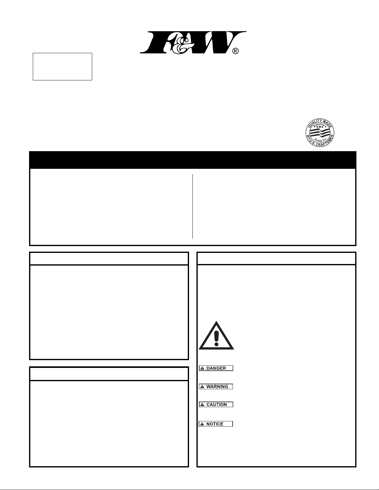
PUMP PERFORMANCE DATA
10 GPM Models
PUMP PERFORMANCE CURVE
FEET
METERS
400
120
112
104
96
88
80
72
64
56
48
40
TOTAL DYNAMIC HEAD
32
24
16
8
0
GALLONS
LITERS
3/4 HP- 12 STAGE
360
320
280
1/2 HP- 8 STAGE
240
200
1/2 HP- 6 STAGE
160
120
80
40
2 4 6 8 10 12 14 16 18
0 8 16 24 32 40 48 56 64
Part Number HP Voltage Phase Amps Stages Height
F5030-0005‡ 1/2 115 1 12.0 6 22-3/8”
F5030-0006‡ 1/2 230 1 6.0 6 22-3/8”
F5030-0007‡ 1/2 115 1 12.0 8 25-1/4”
F5030-0008‡ 1/2 230 1 6.0 8 25-1/4”
F5030-0009‡ 3/4 230 1 8.0 12 29-15/16”
‡Includes 10 feet of #14-2G SJ0W-A power cord
10 GPM
1 1/4" NPT DISCHARGE
FLOW PER MINUTE
IL0501
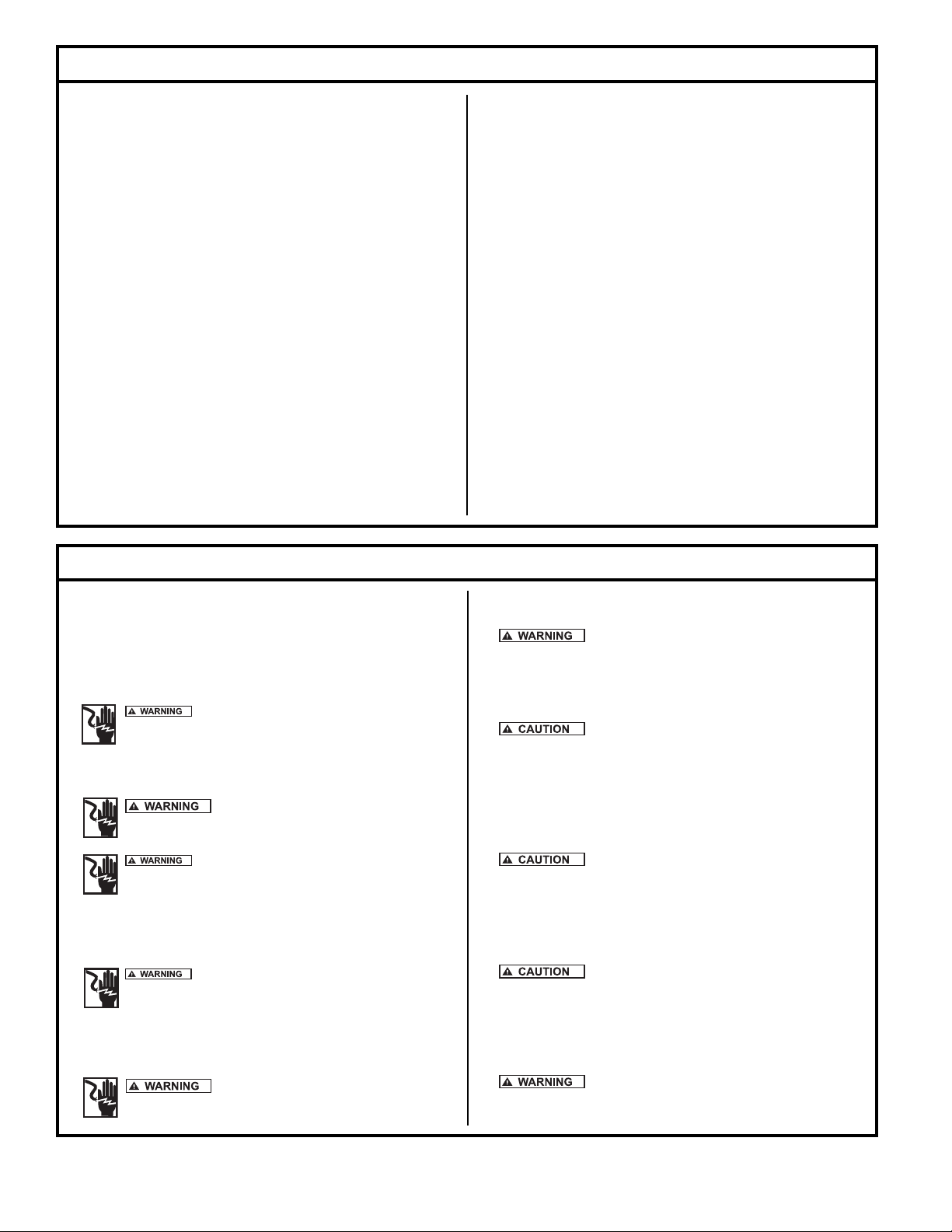
19 GPM Models
PUMP PERFORMANCE CURVE
FEET
METERS
280
80
72
64
56
48
40
32
24
TOTAL DYNAMIC HEAD
16
GALLONS
3/4 HP
240
7 STAGE
200
160
1/2 HP
120
5 STAGE
80
40
8
0
LITERS
0 20 40 60 80 100
Part Number HP Voltage Phase Amps Stages Height
F5031-0005‡ 1/2 115 1 12.0 5 21-15/16”
F5031-0006‡ 1/2 230 1 6.0 5 21-15/16”
F5031-0007‡ 3/4 230 1 8.0 7 25-1/16”
F5031-0008‡ 1 230 1 9.8 9 28-1/8”
‡Includes 10 feet of #14-2G SJ0W-A power cord
19 GPM
1¼" NPT DISCHARGE
1 HP - 9 STAGE
5 10 15 20 25 30
FLOW PER MINUTE
IL0502
015414
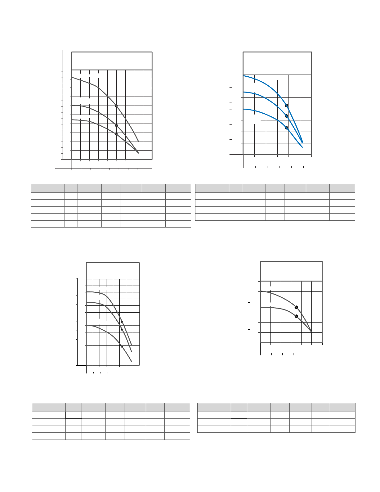
27 GPM Models
PUMP PERFORMANCE
CURVE 27 GPM
FEET
METERS
1-1/4” NPT DISCHARGE
80
260
240
72
1 HP- 7 STAGE
220
64
3/4 HP
200
6 STAGE
56
180
160
48
140
40
1/2 HP- 4 STAGE
120
TOTAL DYNAMIC HEAD
32
100
80
24
60
16
40
8
20
0
GALLONS
LITERS
Part Number HP Voltage Phase Amps Stages Height
F5032-0005‡ 1/2 115 1 12.0 4 21-3/16”
F5032-0006‡ 1/2 230 1 6.0 4 21-3/16”
F5032-0007‡ 3/4 230 1 8.0 6 24-3/16”
F5032-0008‡ 1 230 1 9.8 7 26-7/16”
‡Includes 10 feet of #14-2G SJ0W-A power cord
5 10 15 20 25 30 35 40
0 20 40 60 80 100 120 140
FLOW PER MINUTE
IL0503
35 GPM Models
PUMP PERFORMANCE
FEET
METERS
120
32
100
80
24
TOTAL DYNAMIC HEAD
60
16
40
8
20
0
GALLONS
LITERS
Part Number HP Voltage Phase Amps Stages Height
F5033-0005‡ 1/2 115 1 12.0 2 18-7/8”
F5033-0006‡ 1/2 230 1 6.0 2 18-7/8”
F5033-0007‡ 3/4 230 1 8.0 3 20-1/4’
‡Includes 10 feet of #14-2G SJ0W-A power cord
CURVE - 35 GPM
2” NPT DISCHARGE
3/4 HP - 3 STAGE
1/2 HP - 2 STAGE
10 20 30 40 50 60
0 40 80 120 160 200
FLOW PER MINUTE
IL0504
© Copyright 2007. All Rights reserved.
3
Page 4

PUMP PERFORMANCE DATA
55 GPM Models
PUMP PERFORMANCE CURVE
55 GPM
FEET
METERS
75
20
50
15
10
TOTAL DYNAMIC HEAD
1/2 HP-1 STAGE
25
5
0
GALLONS
LITERS
0 40 80 120 160 200 240 280 320 360
10 20 30 40 50 60 70 80 90 100
2" NPT DISCHARGE
FLOW PER HOUR/MINUTE
IL0505
Part Number HP Voltage Phase Amps Stages Height
F5034-0005‡ 1/2‡ 115 1 12.0 1 17-3/4”
F5034-0006‡ 1/2‡ 230 1 6.0 1 17-3/4”
‡Includes 10 feet of #14-2G SJ0W-A power cord
Model HP Motor
115V 230V 20’ 40’ 60’ 80’ 100’ 120’ 140’ 160’ 180’ 200’ 225’ 250’ 275’ 300’ 325’ 350’ Ft.. PSI
F5030-0005 F5030-0006 1/2 2-wire 14.3 13.2 12.0 10.8 9.4 7.6 6.5 177 77
F5030-0007 F5030-0008 1/2 2-wire 14.7 14.2 13.4 12.6 11.7 10.8 9.7 8.3 6.3 2.1 242 105
F5030-0009 3/4 2-wire 15.0 14.6 14.1 13.6 13.1 12.5 12.0 11.3 10.4 9.7 8.5 7.4 5.7 367 159
F5031-0005 F5031-0006 1/2 2-wire 24.6 22.7 20.5 17.9 15.0 10.4 159 69
F5031-0007 3/4 2-wire 24.6 23.3 21.7 20.0 18.2 16.0 13.3 9.6 219 95
F5031-0008 1 2-wire 25.5 24.4 23.2 22.1 20.7 19.4 17.8 16.2 13.7 10.7 5.0 277 120
F5032-0005 F5032-0006 1/2 2-wire 31.0 27.0 22.0 24.0 14.0 122 53
F5032-0007 3/4 2-wire 32.0 30.0 27.0 24.0 21.0 16.0 5.0 191 83
F5032-0008 1 2-wire 34.0 32.0 30.0 27.0 24.0 22.0 18.0 13.0 222 96
F5033-0005 F5033-0006 1/2 2-wire 48.0 39.0 26.0 67 29
F5033-0007 3/4 2-wire 43.0 40.0 31.0 20.0 100 43
F5034-0005 F5034-0006 1/2 2-wire 71.0 31 13
F5034-0007 3/4 2-wire 77.0 64.0 39.0 67 29
Type
Depth to Water Level in Feet - Capacities in Gallons per Minute Maximum
© Copyright 2007. All Rights reserved.
4
Page 5

Electrical Data for Flint & Walling Effl uent Turbine Pumps
Maximum Locked
Fuse/Circuit
HP Volts Phase Hz S.F.
Rotor
KVA
Breaker Amps
Code
Amps Watts Std. Delay
1/2 115 1 60 1.6 12 970 64.4 R 30 15 1.0 - 1.3
1/2 230 1 60 1.6 6 970 32.2 R 15 8 4.2 - 5.2
3/4 230 1 60 1.5 8 1325 40.7 N 20 10 3.0 - 3.6
1 230 1 60 1.4 9.8 1600 48.7 N 25 11 2.2 - 2.7
Amps
Major Components
1. Submersible Effl uent Turbine Pump - A submersible ef fl u ent
tur bine pump is a multistage centrifugal design pump. Each stage
con sists of an impeller and diffuser. Water pres sure in creas es in
equal amounts as it passes from stage to stage. The more stag es,
the higher the pressure the pump will de vel op.
switch es can result in failure of the pump and void the warranty.
A minimum of two fl oat switches should be used in each ap pli -
ca tion:
• A pump control fl oat switch
• A high water alarm fl oat switch
Winding
Resistant
Line to
Line
To correctly select a pump for a specifi c application, the fol low ing
information must be known:
• The amount of discharge required in GPM or LPM
• The total dynamic head required in feet or meters
Use this information along with the performance data found on the
previous page to make your selection.
2. Control Panel - Submersible effl uent turbine pumps re quire the
use of an above ground control panel or junction box with a pump
control switch for proper op er a tion. Op er a tion of these pumps
without a control pan el or junction box with a pump control switch
can result in failure of the pump and void the war ran ty.
3. Float Switches - All submersible effl uent turbine pumps are non-
au to mat ic. The use of fl oat switches are required for the proper
operation of the pump. Operation of these pumps without fl oat
4. Piping - The submersible effl uent turbine pump can be in stalled
with schedule 40 PVC pipe. The pipe size should be 1¼” diameter
for the 10 GPM to 27 GPM pump series and 2” diameter for the 35
GPM pump series.
General piping from the pump to a splitter, distribution box, drain
fi eld etc., should be the same diameter as stat ed above. For long
pipe runs consult friction loss tables for correct pipe sizing.
5. Check Valve - A check valve is required in all duplex sys tems. It is
also required when a large amount of effl uent can backfl ush into the
system causing rapid cycling of the pump.
A 1/8” weep hole must be drilled in the side of the discharge
head when using a check valve (see drawing below for drill
location).
© Copyright 2007. All Rights reserved.
5
SK2222
Page 6

Pump Installation and Wiring Diagram
T
1. Submersible ef flu ent turbine pumps may be installed in any
ap pli ca tion where relatively clear effl uent, such as from a dos ing
tank or high head STEP system etc., is being pumped.
2. Pumps should always be installed vertically. Pumps should
never be installed horizontally.
3. Because of their low temperature rise, pumps under 2 HP do
not require a fl ow inducer sleeve.
4. Mount the junction box in its permanent position.
5. Run prewired conduit, or equivalent submersible cable from
the junc tion box to a fused disconnect or, if applicable, the control
panel.
6. Feed the pump power cord and float switch cords into the
junc tion box.
7. Make the connections in the junction box using the wiring
di a grams below. If you are using a con trol panel or a fi ltered STEP
system, follow the wiring di a grams and in struc tions included with
them.
8. An alarm should be used with any system using a pump.
Follow the wiring diagram with the alarm for installation and check
your local codes.
9. Run the appropriate power to the control panel from a fused
(cir cuit breaker) disconnect. The appropriate power supply in for ma tion may be found on the pump nameplate.
10. To provide a suitable ground, a separate ground wire (green or
bare) at least as large as the line conductors is required. It is connected from the electrical disconnect box to the con trol panel, to
the junction box and to the green ground wire of the submersible
motor lead.
11. Always disconnect all power when installing or ser vic ing the
pump.
115 VOLT
FUSED DISCONNECT
(CIRCUIT BREAKER)
115 VOLT LINE
WHITE
BLACK
BLACK
WHITE
GROUND
WHITE
GREEN
WHITE
BLACK
GREEN
JUNCTION
BOX
BLACK
WHITE
BLACK
115V
FLOAT SWITC
230 VOLT
FUSED DISCONNECT
(CIRCUIT BREAKER)
230 VOLT LINE
WHITE
BLACK
BLACK
WHITE
GROUND
WHITE
GREEN
WHITE
BLACK
GREEN
JUNCTION
BOX
BLACK
WHITE
BLACK
230V
FLOAT SWI
115 VOLT
EFFLUENT TURBINE PUMP
1/2HP
SK2221A
230 VOLT
EFFLUENT TURBINE PUMP
1/2HP - 1 1/2HP
SK2221B
© Copyright 2007. All Rights reserved.
6
Page 7

Splicing Underground Wires
Splicing of wires to be buried must be done according to the National Electrical Code. Wire connectors or splicing means installed on conductors
for direct burial shall be listed for such use.
Start-up and Maintenance
Before placing the equipment into operation the following must be
checked:
• Septic tank and/or pump chamber should be pumped and cleaned
prior to in stal la tion in existing system.
• Septic tank and/or pump chamber must be watertight.
• Installation needs to be according to instructions.
• Installation should include an easy access riser and tamper resistant
lid.
• Filter assembly needs to be in place and secure.
• Float tree needs to be in place, secure and adjusted for proper
cycling.
• Make sure fl oat switches are free to move within the basin.
• Be sure electrical connections are watertight and conform
to the Uniform Building Code and the National Electrical
Code (NEC).
• Fill the septic tank and/or pump chamber with water and check the
system for operation.
After installing the pump into the containment area with ad e quate sub mer gence, open the discharge valve fully. Start the unit using manual
controls. If fl ow is appreciably less than rated per for mance, pump may
Troubleshooting and Service Checklist
be air locked. To expel trapped air, jog the unit several times, using
the manual con trols.
Have a qualifi ed electrician take voltage and current mea sure ments
on the black wire of single phase. Record these read ings in the
space provided in the “Owner’s Information” section on the front this
manual for future ref er ence.
Be sure to complete all items such as installing the lid on the riser,
securely closing the control panel, and checking the sys tem op er a tion
have been com plet ed before placing the system into ser vice.
Routine maintenance should include:
• Service fi lter in STEP system and/or septic tank.
• Clean pump screen.
• Make sure the check valve is functioning properly.
• Check wire connections.
• Make sure the weep hole is clear.
• Make sure the fl oat switches are free to move within the basin.
• Make sure there are no leaks in the plumbing.
• Make sure there is no excessive noise while the pump is
running.
ELECTRICAL PRECAUTIONS- Before servicing a pump, always shut off the main power breaker and then unplug
the pump - making sure you are not standing in water and wearing insulated protective sole shoes. Under fl ooded conditions, contact
your local electric company or a qualifi ed licensed electrician for disconnecting electrical service prior to pump removal.
CONDITION
A. Pump will not start or run.
B. Motor overheats and trips over load or
blows fuse.
C. Pump starts and stops too often.
D. Pump will not shut off.
E. Pump operates but delivers little or no
water.
F. Drop in head and/or capacity after a
period of use.
COMMON CAUSES
Check fuse, low voltage, over load open, open or incorrect wiring, open switch, impeller or
seal bound mechanically, defective capacitor or relay when used, motor or wiring shorted.
Float assembly held down. Switch defective, dam aged, or out of adjustment.
Incorrect voltage, negative head (discharge open lower than normal), impeller or seal
bound mechanically, or relay, motor shorted.
Check valve stuck or none installed in long distance line, over load open, level switch(es)
defective, sump pit too small, leak in the system.
Debris under fl oat assembly bound by pit sides or other, switch de fec tive, damaged
or out of adjustment, leak in the system.
Check strainer housing, dis charge pipe, or if check valve is used vent hole must be
clear. Discharge head exceeds pump ca pac ity. Low or incorrect voltage. Incorrect
motor ro ta tion. Capacitor de fec tive. In com ing water con tain ing air or causing air to
enter pump ing chamber.
Increased pipe friction, clogged line or check valve. Abrasive material and ad verse
chem i cals could possibly deteriorate impeller and pump housing. Check line. Remove
unit and inspect.
If the above checklist does not uncover the problem, consult the factory - Do not attempt to service or otherwise disassemble pump.
Service must be by Flint & Walling Authorized Service Stations.
© Copyright 2007. All Rights reserved.
7
Page 8

ALL INSTALLATIONS REQUIRE A FILTER BEFORE THE PUMP.
WARNING!
P/N
ZOELLER
Z
NOTE: Flow must
be directed around
the motor for cooling
on 2 HP and higher
units.
Typical Installations
EFFLUENT
TURBINE PUMP
SEPTIC TANK
WARNING
!
ELECTRICAL SHOCK
HAZARD
P/N 10-1193 REV. A
C
O
Z
0ELLER
Z
PUMP CO.
LOUISVILLE, KY
SK2220
EFFLUENT
TURBINE PUMP
&,).47!,,).').#
95 North Oak Street
Kendallville, IN 46755
(800) 345-9422
FAX (260) 347-0909
www.fi ntandwalling.com
SEPTIC TANK
Quality Products
Since 1866!
SK2219
 Loading...