

Page 1
Operating Instructions & Parts Manual
Please read and save these instructions. Read carefully before attempting to assemble, install, operate or maintain the product described.
Protect yourself and others by observing all safety information. Failure to comply with instructions could result in personal injury and/or
property damage! Retain instructions for future reference.
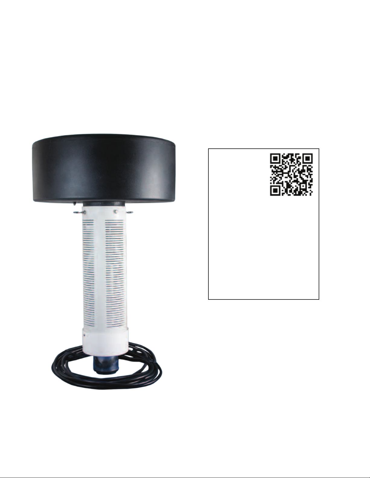
Floating Pond Pump System 1/2, 3/4 & 1 HP
230V Models FPS05021, FPS07021, FPS10021
For installation
videos and other
information, scan
with your smart
phone.
FW1192
0512
Supersedes
0611
1. Introduction
2. Safety
3. Tools required
4. 115V installation
a. Pre-installation
b. Installation
5. 230V installation
a. Pre-installation
b. Installation - pump
c. Installation - control center
d. Setting timers
e. Setting the clock
6. Scheduled maintenance
7. Seasonal removal and storage
023026
Page 2
Operating Instructions & Parts Manual
!
!
!
Floating Pond Pump System 1/2, 3/4 & 1 HP
230V Models FPS05021, FPS07021, FPS10021
Description
This pump system is designed for decorative use and can improve water aeration.
Operates in 5 feet of water or deeper. Do not pump water above 120˚ F. Make
your floating fountain system even more dramatic at night by adding NightBright
lighting system 023069. See specifications for water displacement and fountain
height.
General Safety Information
Carefully read and follow all
safety instructions in this manual
and on pump. Keep safety labels in
good condition. Replace missing or
damaged safety labels.
This is a SAFETY ALERT SYMBOL.
When you see this symbol on
the pump or in the manual, look for
one of the following signal words and
be alert to the potential for personal
injury or property damage.
Warns of hazards
that WILL cause
serious personal injury, death or major
property damage if ignored.
Warns of hazards
that CAN cause
serious personal injury or death, if
ignored.
Warns of hazards
that MAY cause
minor personal injury, product or
property damage if ignored.
IMPORTANT: Indicates factors
concerned with operation, installation,
assembly or maintenance which could
result in damage to the machine or
equipment if ignored.
NOTE: Indicates special instructions
which are important but are not
related to hazards.
Read these
warnings and
instructions carefully. Failure to follow
could result in serious bodily injury
and/or property damage.
This unit
tested for use in swimming
pool areas.
Electrical installations shall be
in accordance with National
Electric Code (NEC) and all applicable
not
local codes and ordinances. A licensed
electrician should perform installation.
Be sure
system is
connected to a
circuit equipped
with a fuse or
circuit breaker of
proper size.
Hazardous voltage.
Can shock, burn
or cause death.
Ground system before
connecting to power
supply.
surfaces or chemicals. DO NOT kink
the power cable. If damaged replace
immediately.
Install all electrical equipment
in protected area to prevent
mechanical damage which could produce
serious electrical shock and/or equipment
failure.
NEVER leave the control box,
fused disconnect switch,
or covers open (either partially or
completely) when not being worked
on by a competent electrician or
repairman.
Always disconnect power source
before performing any work
on or near the motor or its connected
load. If the power disconnect point
is out-of-sight, lock it in the open
position and/or tag it to prevent
unexpected application of power.
Failure to do so could result in fatal
electrical shock or bodily injury.
DO NOT use this system to
as gasoline, fuel oil, kerosene, etc.
Failure to follow the above warning
pump flammable liquids such
Protect the
power cable
from coming
in contact with
sharp objects,
oil, grease, hot
Specifications
230V, 1/2, 3/4 or 1 HP
Requires 5' or greater water depth
100' power cord
Water Lily attachment nozzle displaces:
1/2 HP 4,900 GPH at 15 Ft.
3/4 HP 5,825 GPH at 22 Ft.
1 HP 6,150 GPH at 24 Ft.
Sky Canon attachment nozzle displaces:
1/2 HP 3,300 GPH at 15 Ft.
3/4 HP 4,100 GPH at 35 Ft.
1 HP 4,200 GPH at 41 Ft.
Water Trumpet attachment nozzle
displaces:
1/2 HP 2,700 GPH at 13 Ft.
3/4 HP 3,400 GPH at 20 Ft.
1 HP 3,600 GPH at 22 Ft.
could result in property damage and/or
personal injury.
Unpacking
Unpack and inspect system for damage.
Verify you have received the following
components:
1. Instructions
2. Warranty
3. Pump/float unit.
a. Float with nozzle (Water Lilly 2A)
attached by 4 screws.
b. Screen attached to float by 2
hex bolts with lock washers and
2 eyebolts with hex nuts 180°
apart.
c. 100ft cord secured to bottom cap
with strain relief.
4. Control center.
a. Pump timer
b. Light timer
c. 4 mounting brackets with bolt kit
5. Shrink tube splice kit
6. 2 additional nozzles
a. Sky Cannon (Fig 2)
b. Water Trumpet (Fig 3)
2
95 North Oak St. • Kendallville, IN 46755 • 800-742-5044 • © 2012 All rights reserved.
Page 3

Operating Instructions and Parts Manual
Floating Pond Pump System
INSTALLATION INSTRUCTIONS
Fountain Installation
1. Required Tools and Supplies:
a. 3/8" or larger nylon rope to
anchor/moor fountain unit
b. Stakes or weights to anchor/moor
unit
d. Flat screwdriver
e. 5/16" Nut driver
f. Crimping tool (for cable splicing
only)
g. Torch or heat gun for shrink tube
splice kit(for cable splicing only)
h. Multimeter to check voltage,
current and insulation resistance to
ground
i. Post(s) to mount control center
j. Bolts to attach control center to
post(s)
2. Prepare unit for installation in pond
a. The unit ships with the Water
Lilly nozzle installed. Refer to
Figures 1, 2 and 3 for spray pattern
appearance. To change to one of
the other 2 nozzles, remove the
4 screws with a 5/16” nut driver
or flat screwdriver and replace
with desired nozzle. Nozzles are
marked “This side up”. Make sure
o-ring is seated in groove before
installing nozzle. Tighten screws
until seated, approximately 10 to
12 in-lbs.
b. If installing the optional “Night
Bright” lighting system, follow
instructions included with light
system for proper installation.
c. Determine length and proper
size of cable per Wire Size Table
1. Splice additional cable up to
250 feet total cable length using
included heat shrink splice kit.
DO NOT EXCEED maximum cable
length or use smaller cable than
specified as system damage may
occur.
Never enter the water either
wading, swimming or in a
boat with the pump power on, as this
may result in severe electrical shock.
1. Only install this system in ponds
where no swimming, wading,
boating or fishing is allowed while
system is operating. Disconnect
power to pump before fishing or
entering the water.
2. Post appropriate warning signs per
local and state codes.
3. Install fountain in pond. (See Fig 4
for typical installation).
a. Prior to installation, measure
water depth. All fountains require
5 ft minimum water depth for
proper operation.
b. Position anchor weights or
mooring stakes 180° apart and
equidistant from desired fountain
location. Attach nylon anchor/
mooring ropes to weights or stakes
then attach to 2 eyebolts located
at top of fountain screen. Make
sure to leave only enough slack in
rope to accommodate anticipated
water level fluctuations.
Wiring Sizes Table 1
Wire size for Service Entrance to Fountain control center with 100 ft of 14 AWG pump cable from control center
to fountain
Fountain
HP Rating
1/2 32.2 14 14 14 14 14 12 12 12 10
3/4 40.7 14 14 14 12 12 10 10 10 10
1 48.7 14 14 12 10 10 10 8 8 8
Starting
Current Amps
100 150 200 250 300 350 400 450 500
Length of wire from service entrance to control center
Wire size for Service Entrance to Fountain control center with 250 ft of 14 AWG pump cable from control center
to fountain
Fountain Starting Length of wire from service entrance to control center
HP Rating Current Amps 100 150 200 250 300 350 400 450 500
1/2 32.2 14 14 12 10 10 10 8 8 8
3/4 40.7 10 8 8 6 6 4 4 4 2
1 48.7 10 8 8 6 6 4 4 4 2
Note: 250 ft maximum cable length from control center to fountain pump motor for proper GFI operation.
Wire from service entrance(main fuse/circuit box) to control center must be sized to provide starting current amps at control
center.
Call customer service help line at 1-800-742-5044 for other wire combinations.
3
95 North Oak St. • Kendallville, IN 46755 • 800-742-5044 • © 2012 All rights reserved.
Page 4

Operating Instructions and Parts Manual
!
1/2, 3/4 & 1 HP Models
c. Place power cord so that it rests
on bottom of pond away from
sharp rocks or vegetation so it
can be easily removed without
being damaged or becoming
entangled. Leave enough slack to
accommodate anticipated water
level fluctuations.
NOTE: It is suggested that the
underwater power cables be installed
in conduit from the panel to 4 -5 ft into
the water to prevent possible cable
damage.
4. Before connecting the unit to the
control center, check to insure there
is no leakage to ground. This can be
done by using an ohm meter and
setting the scale to its highest setting
(i.e. Rx100K). Connect one ohmmeter
lead to the unit power cord ground
and to one of the power conductors.
It should read infinite or at least 2
mega ohms. Repeat with the other
conductor. If reading is below 2
mega ohms on either conductor
contact Customer Service Help Line
at 1-800-742-5044.
"NO SWIMMING” AND OR
POSTED PER STATE AND LOCAL CODES.
velocity and can cause bodily injury if
contact is made.
in damp areas. If possible, avoid all
contact with electrical equipment
during thunderstorms or extreme
damp conditions.
WARNING SIGNS SHOULD BE
Water leaving
nozzle is at high
Always use caution when
operating electrical controls
System Control Center
installation and electrical
connection
1. All work must be done in compliance
with local and national electrical
codes by licensed, qualified
electrician. Refer to Fig. 6 in these
instructions or on inside of panel
door for proper wiring.
2. Control Center mounting location.
(See fig. 4 for typical installation)
a. Mount control center a minimum
of 3 feet above ground and a
minimum of 3 feet above the high
water level in a flood zone.
b. Mount control center a minimum
of 5 feet horizontally from
shoreline during maximum flood
condition. (Control center must not
be accessible from water)
c. Always keep control center door
closed, bolted and locked when not
servicing.
3. Have a licensed, qualified electrician
make final connections of fountain
and optional lights to system control
center.
4. Have a licensed, qualified electrician
install disconnecting means in
compliance with local and national
electrical codes.
5. Have a licensed, qualified electrician
make connection to power source.
6. Apply power to unit and set timers
as described in the Setting Timers
section.
7. Test the ground fault interrupter
for proper operation by depressing
the “test” button. (See Fig. 6) The
fountain should shut off. Press the
“reset” button to restart the system.
If pressing the “test” button does not
stop the unit, immediately shut off
power to unit and contact Customer
Service Help Line at
1-800-742-5044.
FAILURE TO CONNECT THIS UNIT
TO A PROPERLY GROUNDED POWER
SUPPLY MAY RESULT IN SEVERE
ELECTRICAL SHOCK.
Setting timers
NOTE: Set the pump timer for all
installations. Set the light timer when
installing the optional NightBright
lighting system.
IMPORTANT: Rotate dial in clockwise
direction only! Rotating dial counter
clockwise will damage timer!
1. Set the on-off time zones.
a) 6 trippers (3 red-on and 3 white-
off) stored below the dial, are
included with each timer for
setting up to 3 on-off time zones.
b) Install the red tripper at the desired
on time and the white tripper at
the desired off time.
c) Rotate the dial clockwise to verify
operation of the trippers.
d) The timer may be overridden by
turning the small on/off dial in the
upper right hand corner of the
timer. Timer will automatically reset
when next time zone occurs unless
manual override was set within 1
hour of on or off cycle.
2. Setting the clock. (24 hr clock)
a) Turn the dial clockwise until the
arrowhead is aligned with the
proper time.
b) The timers include built in battery
backup for maintaining time
during power outages.
4
95 North Oak St. • Kendallville, IN 46755 • 800-742-5044 • © 2012 All rights reserved.
Page 5

T
h
i
s
s
i
d
e
u
p
T
h
i
s
s
i
d
e
u
p
T
h
i
s
s
i
d
e
u
p
Operating Instructions and Parts Manual
Floating Pond Pump System
Disconnect - Install in compliance with
local and national electric codes.
Control center
5 ft. minimum from
shoreline during
maximum flood condition
Pond pump float
Nylon rope secured to weights can
be attached to stakes on shore. Two
required.
To
service
panel
3 Ft. Minimum above
ground and 3 ft.
minimum above high
water level in flood
zone.
14.5"(1/2 HP)
20.0" (3/4 & 1 HP)
8.0"
1/2 HP
20"
Power cord may
require burial.
Refer to local
codes
32"
1/2 HP
15 - 20 ft.
Figure 4 - Typical Installation
NOZZLE PATTERNS
Figure 1 - Water Lily: (Factory Installed)
An eye-catching combination spray.
Item #2A
p
u
e
d
i
s
s
i
h
T
5 ft.
minimum
depth
IL0806
p
u
e
d
i
s
s
i
h
T
Figure 3 - Water Trumpet: A symmetrical
inverted bell shape. Item #2C
3/4 HP
1 HP
24"
28"
100 Ft. Power Cord
Figure 5 - Dimensions
36"
40"
IL0807
3/4 HP
1 HP
p
u
e
d
i
s
s
i
h
T
Figure 2 - Sky Cannon: A dramatic single
plume of water. Item #2
5
95 North Oak St. • Kendallville, IN 46755 • 800-742-5044 • © 2012 All rights reserved.
Page 6

!
Operating Instructions and Parts Manual
1/2, 3/4 & 1 HP Models
INSTALLATION CHECK LIST
Read installation instructions and
warnings.
Post appropriate warning signs.
Install desired spray nozzle.
Install and anchor unit in pond.
Connect control center to properly
grounded supply.
Check insulation resistance to
ground.
Power up unit.
Test operation of GFI by pressing the
“Test” Button. (See Fig 6).
Set Timer.
File instructions for future reference.
DO NOT handle pump with
wet hands or when standing
in water as fatal electrical shock could
occur. Disconnect main power supply
before handling system for any
reason.
MAINTENANCE
1. Test the GFI monthly by depressing
the test button.
2. The screen and nozzle should be
cleaned as required to maintain
proper water flow.
3. At least once a year, thoroughly
inspect the fountain, underwater
cable and anchor/mooring lines
for physical damage. Replace any
damaged components.
WINTER STORAGE
1. Remove fountain from pond.
2. Check for damage.
3. Clean unit prior to storage.
4. In freezing climates, store in heated
space to prevent damage to water
lubricated motor.
The pump motor is
water lubricated
and is factory filled with an antifreeze
solution. During operation the
antifreeze may exchange, thru the
filtered check valve, with the pond
water. In climates where freezing
may occur, the unit must be stored
in a heated storage space to prevent
damage to the motor.
Troubleshooting Chart
Symptom Possible Cause(s) Corrective Action
Unit won’t
run
No or low
spray
GFI Trips 1. Electrical storm can trip GFI 1. Reset GFI.
Unit spins Anchor rope(s) loose Check anchor rope(s) and re-attach if necessary.
1. Circuit breaker tripped
2. Low Voltage
3. GFI Tripped
4. Excessive Cable Length
5. Timer/clock not set
Blocked screen or nozzle,
missing or damaged o-ring, or
incorrectly installed nozzle
2. Short in system
3. Defective power cable
1. Reset circuit breaker.
2. Verify voltage.
3. Reset GFI.
4. Verify acceptable maximum cable length.
5. Set clock to local time and timers for desired cycle. See Section on Setting Timers.
Disconnect power. Clean screen and/or nozzle. Check that o-ring is undamaged and seated
in groove. Check that nozzle is installed properly (nozzles are marked “This side up”).
Check depth of pond. If less than 5 feet deep, move to deeper section. Restart unit.
2. Disconnect power and check cord for damage. If cord is damaged contact customer
service help line at 1-800-742-5044.
3. Disconnect power and check cord for damage. If cord is damaged contact customer
service help line at 1-800-742-5044.
6
95 North Oak St. • Kendallville, IN 46755 • 800-742-5044 • © 2012 All rights reserved.
Page 7

!
Operating Instructions and Parts Manual
Floating Pond Pump System
Never
water either wading,
swimming or in a boat with
the pump power on, as this may result
in severe electrical shock.
Light Timer
Power Load
B
enter the
ON
Power
OFF
Pump Timer
Power
Power Load
B
B/W R/B
W
R
Pump
Motor
Contactor
OFF
ON
B R
known to the State of California to
cause cancer and birth defects or other
reproductive harm.
Ground Fault
Interrupter (GFI)
Power
Reset
Fault
B/W
R/B
Test
This product
contains chemicals
Hazardous voltage.
Can shock, burn
or cause death.
Ground system before
connecting to power
supply.
W
shall be in accordance with National
Electric Code (NEC)
and all applicable
local codes and
ordinances. A
licensed electrician
should perform
installation.
B
H1 H2
To Lights
Electrical
installations
W/B
GRD GRD
P1 P2 L1 N L2
To Pump To Line
Be sure system is connected to a
circuit equipped with a fuse or
circuit breaker of proper size.
NEVER leave the control box,
fused disconnect switch,
or covers open (either partially or
completely) when not being worked
on by a competent electrician or
repairman.
Figure 6 - Control Center Schematic
WB R
IL0809
Always disconnect power source
before performing any work
on or near the motor or its connected
load. If the power disconnect point is
out-of-sight, lock it in the open position
and/or tag it to prevent unexpected
application of power. Failure to do so
could result in fatal electrical shock or
bodily injury.
7
95 North Oak St. • Kendallville, IN 46755 • 800-742-5044 • © 2012 All rights reserved.
Page 8

T
h
i
s
s
i
d
e
u
p
T
h
i
s
s
i
d
e
u
p
T
h
i
s
s
i
d
e
u
p
Operating Instructions and Parts Manual
Ref
No. Description
Screw - #10 x 3/4 Slotted Hex
*
Head or Pan Head Sheet Metal
Screw (18-8 Stainless Steel)
2A Nozzle - Water Lily
2B Nozzle - Sky Cannon
2C Nozzle - Water Trumpet
O-Ring - AS568A - 041 (3” ID x
3
3/18” OD)
4 Bolt - SS 1/4-20 x 3/4
5 Lockwasher SS - 1/4”
6 Mounting Flange
7 Float
8 Pump End
9 Motor 230V
10 Locknut - SS 5/16-24
11 100 ft. power cord
12 Eye Bolt - SS 1/4-20 x 2-1/2
12A Bolt - SS - 1/4 - 20
13 Locknut - SS 1/4--20
14 Screen
15 Screen Cap
16 Strain Relief
Warning Decal
Splice Kit
Timer (pump or light)
GFI
Contactor
(*) Standard hardware item, available locally
() Not Shown
1/2 HP 3/4 HP 1 HP Qty
* * *
021617 021617 021617
021618 021618 021618
021619 021619 021619
021622 021622 021622
* * *
* * *
021707 021707 021707
022912 022523 022523
021713 022999 023000
022985 022517 022986
127021 127021 127021
022516 022516 022516
* * *
* * *
* * *
022913 022913 022694
021611 021611 021611
021613 021613 021613
021625 021625 021625
022919 022919 022919
022697 022697 022697
022698 022698 022698
022902 022902 022902
() In control center
Part No.
1
2(A/B/C)
3
5
6
1
1
4
1
1
4
6
7
6
1
1
12
1
1
4
13
12A
5
1
2
2
8
2
1
1
11
1
2
1
1
1
10
1
9
14
1
15
11
Flow (GPH)
1/2 HP 4900
3/4 HP 5825
1 HP - 6150
1/2 HP 3300
3/4 HP 4100
1 HP 4200
1/2 HP 2700
3/4 HP 3400
1 HP 3600
Spray
Height (Ft.)
15
22
24
15
35
41
13
20
22
Pattern
Image
p
u
e
d
i
s
s
i
h
T
p
u
e
d
i
s
s
i
h
T
p
u
e
d
i
s
s
i
h
T
Pattern Name
Water Lily - 2A
(Factory Installed)
Sky Cannon - 2B
Water Trumpet
- 2C
15
16
11
Figure 7 - Parts Illustration for Floating Pond
System
IL0808
IL0538
 Loading...