

Page 1
Operating Instructions & Parts Manual
!
Please read and save these instructions. Read carefully before attempting to assemble, install, operate or maintain the product
described. Protect yourself and others by observing all safety information. Failure to comply with instructions could result in
personal injury and/or property damage! Retain instructions for future reference.
Floating Pond Pump System
Models FPS0501 and SPS0501
FW0779
1013
Supersedes
0512
Description
This pump system is designed for decorative use and can
improve water aeration. It produces water fountains up to 15’
in height, and up to 4,900 gallons of water per hour. Make
your floating fountain system even more dramatic at night by
adding the NightBright lighting system 023069.
Operates in 5 feet of water or deeper.
Unpacking
When unpacking the unit, inspect carefully for any damage
that may have occurred during transit.
For installation
videos and other
information, scan
with your smart
phone.
1. Introduction
2. Safety
3. Tools required
4. 115V installation
a. Pre-installation
b. Installation
5. 230V installation
a. Pre-installation
b. Installation - pump
c. Installation - control center
d. Setting timers
e. Setting the clock
6. Scheduled maintenance
7. Seasonal removal and storage
General Safety Information
Carefully read and follow all safety instructions in this
manual and on pump. Keep safety labels in good condi-
tion. Replace missing or damaged safety labels.
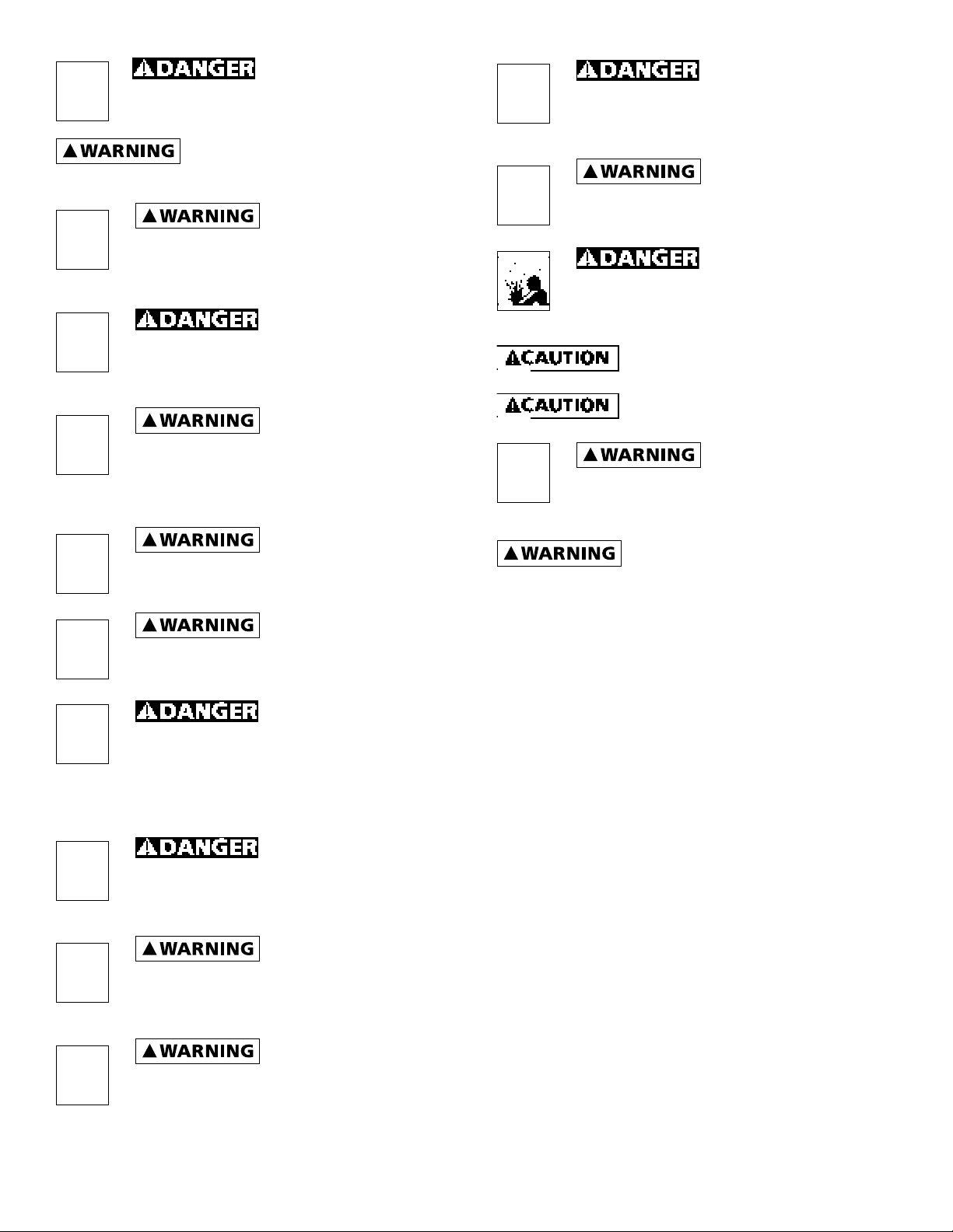
This is a SAFETY ALERT SYMBOL. When you see
this symbol on the pump or in the manual, look for one of
the following signal words and be alert to the potential for
personal injury or property damage.
Warns of hazards that WILL cause serious
personal injury, death or major property damage if ignored.
95 North Oak St. • Kendallville, IN 46755 • 800-742-5044 • © 2013 All rights reserved.
Warns of hazards that CAN cause serious
personal injury or death, if ignored.
Warns of hazards that MAY cause minor
personal injury, product or property damage if ignored.
IMPORTANT: Indicates factors concerned with operation,
installation, assembly or maintenance which could result in
damage to the machine or equipment if ignored.
NOTE: Indicates special instructions which are important but
are not related to hazards.
1
021626
Page 2
Never enter the water
!
!
!
!
!
!
!
!
!
!
either wading, swimming or in a boat with the
pump power on, as this may result in severe
electrical shock.
Read these warnings and instructions
carefully. Failure to follow could result in serious bodily
injury and/or property damage.
Electrical installations
shall be in accordance with National Electric
Code (NEC) and all applicable local codes
and ordinances. A licensed electrician should
perform installation.
“NO SWIMMING” AND
OR WARNING SIGNS SHOULD BE POSTED PER
STATE AND LOCAL CODES.
Please affix included warning label to power
receptacle or junction box.
System furnished with a
100ft power cord with three prong GFI plug. –
Must connect to properly grounded receptacle
of grounding type. Do not remove ground
pin on plug. Do not extend the cord length by splicing or
with an extension cord.
Always use caution when
operating electrical controls in damp areas.
If possible, avoid all contact with electrical
equipment during thunderstorms or extreme
damp conditions.
Install all electrical
equipment in protected area to prevent
mechanical damage which could produce serious
electrical shock and/or equipment failure.
DO NOT use this system to
pump flammable liquids such as gasoline, fuel
oil, kerosene, etc. Failure to follow the above
warning could result in property damage and/
or personal injury.
Do not pump water above 120 degrees
Fahrenheit.
Water leaving nozzle is at high velocity
and can cause bodily injury if contact is made.
This unit not tested for use
in swimming pool areas.
FAILURE TO CONNECT
THIS UNIT, WITH THE GFI, TO A PROPERLY
GROUNDED RECEPTACLE MAY RESULT IN
SEVERE ELECTRICAL SHOCK.
Be sure system is connected
to a circuit equipped with a fuse or circuit
breaker of ample capacity.
Always disconnect power
source before performing any work on or
near the motor or its connected load. If the
power disconnect point is out-of-sight, lock it
in the open position and/or tag it to prevent unexpected
application of power. Failure to do so could result in fatal
electrical shock or bodily injury.
DO NOT handle pump with
wet hands or when standing in water as
fatal electrical shock could occur. Disconnect
main power supply before handling system
for any reason.
Protect the power cable
from coming in contact with sharp objects,
oil, grease, hot surfaces or chemicals. DO
NOT kink the power cable. If damaged
replace immediately.
GFI plug must be oriented with cord
coming out the bottom and protected from direct rainfall.
INSTALLATION INSTRUCTIONS
1. Only install this system in ponds where no swimming,
wading, boating or fishing is allowed while fountain is
operating. Disconnect power to pump before fishing or
entering the water.
2. Post appropriate warning signs per local and state codes.
3. Inspect pump system for damage before installing in
pond. Check that all bolts and screws are tight. Check for
any bent prongs or a cracked case on the GFI.
4. The unit ships with one spray nozzle attached. To change
to one of the other 2 nozzles, remove the 4 screws from
the nozzle then replace with desired nozzle. Refer to
Figures 1, 2 & 3 for spray pattern appearance. Nozzles
are marked “This side up.” Make sure the o-ring is
seated in groove before installing nozzle. Tighten screws
until seated, approximately 10 to 12 in-lbs.
5. Attach nylon anchor ropes to 2 eyebolts located at top
of screen. Secure (make sure rope is tight) to weights
placed on pond floor or stakes on pond shore. When
using weights to anchor the pump, place weights
approximately 10 feet from unit, 180 degrees apart.
box, fused disconnect switch, or covers open
(either partially or completely) when not
being worked on by a competent electrician
or repairman.
NEVER leave the control
2
95 North Oak St. • Kendallville, IN 46755 • 800-742-5044 • © 2013 All rights reserved.
Page 3

6. Before connecting the unit to the power receptacle,
5 Feet Minimum Depth
Approved outdoor grounded
check to insure there is no leakage to ground. This can
be done by using an ohm meter and setting the scale to
its highest setting (i.e. Rx100K). Connect one ohmmeter
lead to the unit power cord ground (round prong) and
to one of the flat prongs. It should read infinite or at
least 2 mega ohms. Repeat with the other prong. If
reading is below 2 mega ohms on either prong contact
Customer Service Help Line listed at bottom of page.
7. Do Not Operate System on an Extension Cord. If no
power is accessible at the pond, contract a licensed
electrician to install the proper power supply in
accordance with National Electric Code and all
applicable local codes and ordinances.
8. After installing the unit, checking ground and
connecting power to the unit, the unit can be powered
up. Check operation of the GFI by pushing the “Test”
button, the unit should stop. Pushing the “Reset” button
should restart the unit. If pressing the “test” button
does not stop the unit, immediately shut off power to
unit and contact Customer Service Help Line listed at
bottom of page.
NOZZLE PATTERNS
p
u
e
d
i
s
s
i
h
T
Figure 3: Water Trumpet - A symmetrical inverted bell shape.
Item #2C
receptacle with GFI protected plug
Power cord may require
burial. Refer to local codes
Figure 4: Typical Installation
15 - 20
Feet
Pond Pump Float
Nylon rope secured to weights
can be attached to stakes on
shore. 2 Required.
L0535
p
u
e
d
i
s
s
i
h
T
Figure 1: Water Lily - An eye-catching combination spray.
Item #2A
p
u
e
d
i
s
s
i
Figure 2: Sky Cannon - A dramatic single plume of water.
Item #2B
h
T
INSTALLATION CHECK LIST
Read installation instructions and warnings
Post appropriate warning signs
Install desired spray nozzle
Install and anchor unit in pond
Check insulation resistance to ground
Power up unit
Test operation of GFI by pressing the “Test” Button.
File instructions for future reference
REQUIRED TOOLS & SUPPLIES
• #2 Phillips screwdriver
• Nylon rope to anchor unit
• Stakes or weights for anchoring unit
• Ohm meter to check insulation resistance to ground
WINTER STORAGE
• Rinse unit with clean water to remove any build-up on
unit.
• Check unit for any damage.
• Store unit in heated space in freezing climates.
The pump motor is water lubricated and is factory filled
with an antifreeze solution. During operation the antifreeze
may exchange, thru the filtered check valve, with the pond
water. In climates where freezing may occur, the unit must
be stored in a heated storage space to prevent damage to
the motor.
3
95 North Oak St. • Kendallville, IN 46755 • 800-742-5044 • © 2013 All rights reserved.
Page 4

TROUBLESHOOTING GUIDE
PROBLEM POSSIBLE
CAUSES
Unit won’t
run
No or low
spray
GFI Trips Electrical
Unit spins Anchor rope
Circuit breaker tripped
GFI Tripped Reset GFI
Blocked
screen or
nozzle, missing or damaged o-ring,
or incorrectly
installed
nozzle
storm can trip
GFI
Short in system
loose
CORRECTIVE ACTION
Reset circuit breaker
Disconnect power. Clean screen
and/or nozzle. Check that o-ring is
undamaged and seated in groove.
Check that nozzle is installed properly (nozzles are marked “This side
up”). Check depth of pond. If less
than 5 feet deep, move to deeper
section. Restart unit.
Reset GFI
Disconnect power and check cord
for damage. If cord is damaged
contact Customer Service Help
Line listed at bottom of page for
replacement.
Check anchor rope and re-attach if
necessary
1
2(A/B/C)
3
4
5
6
17
7
8
10
9
11
13
12
14
1
Item # Qty Part No. Description
Screw - #10 x 3/4 Slotted Head or Pan
* 6 *
Head Sheet Metal Screw (18-8 Stainless
Steel)
2A 1 021617 Nozzle - Water Lily
2B 1 021618 Nozzle - Sky Cannon
2C 1 021619 Nozzle - Water Trumpet
3 1 021622 O-Ring - AS568A - 041 (3” ID x 3/18” OD)
4 6 021628 Bolt - SS 1/4-20 x 3/4
5 6 021629 Lockwasher - 1/4”
6 1 021707 Mounting Flange
7 1 022912 Float
8 1 021713 Pump End
9 1 021740 Motor 1/2 HP 115V
10 4 127021 Locknut - SS 5/16-24
11 1 021715 100 ft. power cord with GFI
11A 1 021614 GFI
12 2 021609 Eye Bolt - SS 1/4-20 x 2-1/2
13 2 021623 Locknut - SS 1/4--20
14 1 022913 Screen
15 1 021611 Screen Cap
16 1 021613 Strain Relief
17 2 021625 Warning Decal
*Standard hardware item, available locally
15
11A
11
Flow (GPH)
4900 15
3300 15
2700 13
15
16
11
Spray Height
(Ft.)
Pattern
Image
p
u
e
d
i
s
s
i
h
T
p
u
e
d
s
s
i
h
T
p
u
e
d
i
s
s
i
h
T
IL0538
Pattern
Name
Water Lily
- 2A
Sky Cannon
- 2B
Water
Trumpet - 2C
4
95 North Oak St. • Kendallville, IN 46755 • 800-742-5044 • © 2013 All rights reserved.
 Loading...