

Page 1

INSTALLATION, OPERATION, AND
MAINTENANCE MANUAL
CVSM30, CSM30, CVSM45, CSM45, CST45,
CSIM34, CSM60, CSIM68
PP0132
0611
Supersedes
0410
AUTOMATIC WATER
CONDITIONERS
FILL IN FOR FUTURE REFERENCE
MODEL NO:___________________________________________
DATE INSTALLED:______________________________________
DEALER:______________________________________________
023366
Page 2

remier
remier
P
P
roducts
roducts
®
P
P
WATER TREATMENT
Model Number Units
Automatic Water Conditioners
SPECIFICATION TABLE
CVSM30
CSM30
CSM60
CVSM45
CSM45
CST45 CSIM34 CSIM68
Exchange Capacity
Kilograins
Salt Per
Regeneration
Lbs. / Regen.
Max. Service Flow
Operating Pressure
Mineral Tank Size
Brine Tank Size
Softener Resin
Shipping Weight Lbs.
Overall Height Inches 52 62 52 52 52 60
Regeneration
(1)
Pressure drop not to exceed 15 PSI
(2)
Product materials and workmanship are protected with a written warranty
(3)
Untreated water provided during all steps of regeneration
*Requires 1.0 cu. ft. fine mesh resin plus 30 lbs. garnet underbed
**Requires 2.0 cu. ft. fine mesh resin plus 60 lbs. garnet underbed
(1)
Pipe Size
Range
Maximum
Operating
Temperature
(Dia. x Ht.)
(Dia. x Ht.)
Salt Storage Lbs. 225 225 225 225 225 225
Volume
Tannin Resin Cu. Ft. N/A N/A N/A .5 N/A N/A
Electrical
Max. Drain
Flow During
(2)
(3)
(3)
Max 30,000 60,000 45,000 30,000 34,000 68,000
Min 18,000 32,000 27,000 18,000 18,000 34,000
Max 15 30 22 15 15 30
Min 6 12 9 9 9 12
GPM 8 12 9 5 10 12
In / Out -
Inches
PSI 30 - 125 30 - 125 30 - 125 30 - 125 30 - 125 30 - 125
Degrees F 110 110 110 110 110 110
Inches 8 x 44 10 x 54 10 x 44 10 x 44 10 x 44 12 x 52
Inches 14 x 14 x 34 14 x 14 x 34 14 x 14 x 34 14 x 14 x 34 14 x 14 x 34 14 x 14 x 34
Cu. Ft. 1.0 2.0 1.5 1.0 1.0* 2.0**
Volt
Freq.
GPM 1.3 2.7 2.2 2.2 2.7 2.7
1 1 1 1 1 1
120 Volts
60 Hz
90
92
120 Volts
60 Hz
147
120 Volts
60 Hz
120
122
120 Volts
60 Hz
116.5 120.5 175.5
120 Volts
60 Hz
120 Volts
60 Hz
Premier Products Water Treatment | 95 North Oak St. | Kendallville, IN 46755 | 800-545-2206 | flintandwalling.com
Copyright © 2011 Flint & Walling All Rights Reserved.
2
Page 3
remier
remier
P
P
roducts
roducts
®
P
P
WATER TREATMENT
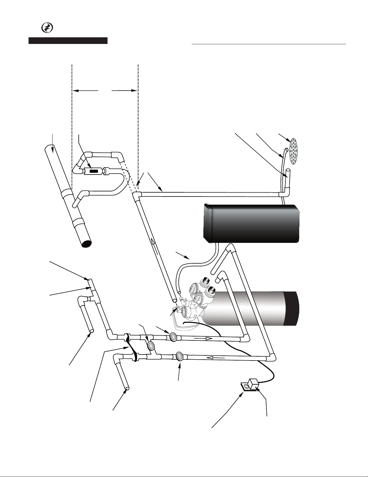
Connection to sanitary sewer line
(optional)
Sanitary sewer line
Air gap device
Maximum drain pipe
elevation above drain
port is 5 ft.
Drain
Automatic Water Conditioners
IL1054
Do not make a direct connection
to the drain. An air gap must
Brine Tank Overflow drain 1/2” ID
diameter minimum size
(gravity flow)
Drain line 1/2” diameter ID
minimum size
Sanitary Drain, Floor Drain or
be present.
Laundry Tubs are acceptable.
Drain Trap
Cold hard water inlet
30 p.s.i. minimum pressure
3/4” minimum pipe size
High Pressure Warning:
If feedwater pressure is known to be above
125 PSI, it is strongly recommended that a
pressure reducing valve be installed at this point.
Manual Bypass Valve
(Normally Closed)
(optional)
Manual Inlet Valve
Drain Port
(optional)
Brine Line Tubing
Assembly
Brine Tank
Assembly
Mineral Tank
Typical Water Softener Installation
Hard water to Sprinklers and any
dersired unsoftened fixtures
Ground Strap
Softened Water Outlet
Premier Products Water Treatment | 95 North Oak St. | Kendallville, IN 46755 | 800-545-2206 | flintandwalling.com
Copyright © 2011 Flint & Walling All Rights Reserved.
Manual Outlet Valve
(optional)
110-125 Volt
Continuous Power Supply
Transformer
3
Page 4

remier
remier
P
P
roducts
roducts
®
P
P
WATER TREATMENT
Automatic Water Conditioners
INSTALLATION FITTING ASSEMBLIES
Installation fittings connect to the control valve or
the bypass valve using nuts that only require hand
tightening. Hand tight nut connections between
control valve and installation fittings, control valve and
bypass valve, and bypass valve and installation fittings
allow for ease serviceability. Do not use a pipe wrench
to tighten nuts on installation fittings. Hand tighten
only.
Split ring retainer design holds the nut on and allows
load to be spread over the entire nut surface area,
reducing the chance for leakage. The split ring design
incorporated into the installation fittings allows
approximately 2 degrees off axis alignment to the
plumbing system. The installation fittings are designed
to accommodate minor plumbing misalignments but
are not designed to support the weight of a system or
the plumbing.
When assembling the installation fitting package,
connect the fitting to the plumbing system first and
then attach the nut, split ring and o-ring. Heat from
soldering or solvent cements may damage the nut,
split ring or o-ring. Solder joints should be cool and
solvent cements should be set before installing the nut,
split ring and o-ring. Avoid getting primer and solvent
cements on any part of the o-rings or split rings, bypass
valve or control valve. Solvent cements and primers
should be used in accordance with the manufacturer’s
instructions.
Slip the nut onto the fitting first, then the split ring
second and the o-ring last. Hand tighten the nut. If the
fitting is leaking, tightening the nut will not stop the
leak. Remove the nut, remove the fitting, and check
for damage or misalignment of the o-ring.
Do not use pipe dope or other sealant on threads.
Teflon tape must be used on the threads of the 1”
NPT connection and on the threads for the drain line
connection. Teflon tape is not necessary on the nut
connection or caps because of o-ring seals.
Do not use Vaseline, oils or other unacceptable
lubricants on o-rings. A silicon lubricant may be used
on black o-rings.
BYPASS VALVE - CSM MODELS ONLY
The bypass valve easily connects to the control valve
body using nuts that only require hand tightening.
Hand tighten nut connections between control valve
and fittings, control valve and bypass valve, and
bypass valve and installation fittings allow for easy
serviceability. The split ring retainer design holds the
nut on and allows load to be spread over the entire
nut surface area, reducing the chance for leakage.
The split ring design, incorporated into the bypass,
allows approximately 2 degrees off axis alignment
to the plumbing system. The bypass is designed to
accommodate minor plumbing misalignments but is
not designed to support the weight of a system or the
plumbing.
Avoid getting primer and solvent cements on any
part of the o-rings or split rings, bypass valve or
control valve. Do not use pipe dope or other sealant
on threads. Teflon tape is not necessary on the caps
because of o-ring seals.
Do not use Vaseline, oil or other unacceptable
lubricants on o-rings. A silicon lubricant may be used
on black o-rings.
A. GENERAL
1. Shut off all water at main supply valve.
2. Shut off the fuel supply to water heater.
3. Open faucets (hot and cold) nearest pump or water
meter to relieve pressure and drain system.
4. Move softener into the installation position.
Loosely attach all fittings to measure for bypass
valve assembly (if used), or manual bypass valve.
5. Level the unit. Place shims under cabinet or brine
tank as needed. (Do Not use metal shims.)
6. Cut the cold water supply line as required.
7. Install the bypass valve assembly if used.
B. PLANNING INSTALLATION
1. All installation procedures must conform to local
plumbing, electrical and sanitation codes and
ordinances.
2. It is recommended that outside faucets for lawn
service be on the hard water line, ahead of the
softener, to conserve softened water, save salt and
prevent lawn damage.
3. If this isn’t practical, use the convenient integral
bypass valve assembly.
CAUTION: The inlet water temperature MUST NOT
exceed 110° F.
4. Do not locate softener where ambient temperature
drops below 40° F.
5. Allow space around the softener for ease of
servicing.
6. The softener drain lines must never be solidly
connected to the sewer line. (Always provide an
air gap at the END of the drain line). Valve drain
Premier Products Water Treatment | 95 North Oak St. | Kendallville, IN 46755 | 800-545-2206 | flintandwalling.com
Copyright © 2011 Flint & Walling All Rights Reserved.
4
Page 5

remier
remier
P
P
roducts
roducts
®
P
P
WATER TREATMENT
Automatic Water Conditioners
line must not be elevated over 5’ from the top of
the softener on well systems, and not over 8’ on
municipal water systems.
7. The salt storage cabinet or brine tank is a gravity
drain, and this drain line must be lower than the
drain fitting on the side wall of the cabinet.
8. Move the softener into position and connect to
bypass assembly (if used). The integral manual
bypass option is a connection which eliminates the
need for a 3-valve manifold. This makes installation
easier and provides a more convenient method of
bypassing.
9. IMPORTANT: Be sure that the water inlet line is
connected to the “inlet” side of the bypass valve
or to the inlet fitting. (Bypass valve inlet/outlet
fittings are marked.) If water lines are reversed,
(inlet/outlet) resin may be forced from the water
softener into the household plumbing system. If
this occurs, household plumbing system must be
flushed clean.
C. CONNECT ALL FITTINGS (refer to previous
page)
CAUTION: Care must be used when working with
copper tubing. Do not allow the flame from torch
to contact any portion of the Valve assembly.
1. Attach 1/2” ID drain line to drain elbow with insert
and nut.
2. Do not elevate the drain line over 5’ above the top
of the valve (8’ on municipal systems) or exceed 25’
in length at either height.
CAUTION: An air gap must be provided upon
sewer entry. (Conform to local plumbing and
sanitation codes and ordinances).
3. The salt storage cabinet or brine tank provides an
overflow. Attach 1/2” ID flexible plastic tubing to
the overflow fitting and direct it to the drain. DO
NOT connect to the main drain line. Use a separate
gravity flow line.
D. PRESSURE TEST THE INSTALLATION
The plumbing system can now be checked for any
possible leaks.
1. Put the unit into backwash. To do this, push and
hold the
valve stops cycling, unplug the unit. With water
supply off, put the bypass into the service position.
2. Open water supply line valve very slowly. Water
should escape slowly from the drain line. If water
enters too quickly, resin may be lost to the drain.
REGEN
button for 3-5 seconds. When the
3. When all of the air has been purged from the
mineral tank (water flows steadily from the drain),
open the main supply valve fully.
4. Allow water to run to drain until clear. CHECK FOR
LEAKS!
5. Plug the unit back in.
6. Manually step the unit through the remaining
steps, stopping at the fill cycle. (To do this, push
REGEN
the
screen). Once the piston has stopped moving,
push the
Continue until FILL appears on the screen. The
unit will now fill the brine tank to the appropriate
level. (This sequence is for softeners with post fill
brine).
7. Allow control to return to the home position.
8. CHECK FOR LEAKS!
9. Make sure the power cord is plugged into a
properly grounded wall receptacle.
button. The unit will say Brine on the
REGEN
button again to the next cycle.
E. PROGRAMMING THE CONTROL VALVE
When in operation, normal user displays such as time
of day, gallons remaining or days remaining before
regeneration are shown. When stepping through
a procedure, if no buttons are pressed within five
minutes, the display returns to a normal user display.
Any changes made prior to the five minute time out
are incorporated. The one exception is current flow
rate display under the diagnostic procedure. The
current flow rate display has a 30 minute time out
feature.
CONTROL VALVE CYCLES OF OPERATION
REGENERATION CYCLES
1st Cycle Backwash Normal
2nd Cycle Brine / Slow Rinse
3rd Cycle Backwash Normal
4th Cycle Rapid Rinse
5th Cycle Brine Tank Refill
General Operation
When the system is operating, one of two displays
will be shown. Pressing
the displays. One of the displays is always the current
time of day. The second display is gallons remaining.
Capacity remaining is the number of gallons that
will be treated before the system goes through a
regeneration cycle. The user can scroll between the
displays as desired.
will alternate between
NEXT
Premier Products Water Treatment | 95 North Oak St. | Kendallville, IN 46755 | 800-545-2206 | flintandwalling.com
Copyright © 2011 Flint & Walling All Rights Reserved.
5
Page 6

remier
remier
P
P
roducts
roducts
®
P
P
WATER TREATMENT
If the system has called for a regeneration
that will occur at the present time of
regeneration, the words “REGEN TODAY” will
appear on the display.
When water is being treated (i.e. water
is flowing through the system), the word
“SOFTENING” flashes on the display.
Automatic Water Conditioners
REGEN TODAY will be
displayed if a regeneration
is expected “Tonight.”
IL1067
STEP 1U
STEP 2U
STEP 3U
AM
PM
IL1068
Set Time of Day
The user must set the time of day. Time of day should only need to be
set initially, and after power outages lasting more than 8 hours, if the
battery has been depleted and a power outage occurs, or when daylight
saving time begins or ends. If a power outage lasting more than 8 hours
occurs, the time of day will flash on and off, which indicates the time of
day should be reset. If a power outage lasts less than 8 hours and the time
of day flashes on and off, the time of day should be reset and the battery
replaced.
STEP 1U - Press
STEP 2U - Current Time (hour): Set the hour of the day using or
buttons. AM/PM toggles after 12. Press
STEP 3U - Current Time (minutes): Set the minutes of the day using
or buttons. Press
previous step.
Power Loss
If the power goes out, the system will keep time for up to 8 hours or until
the battery is depleted. If a power outage of more than 8 hours occurs,
the time of day will flash on and off, which indicates the time of day
should be reset. The system will remember the rest. If a power outage
lasts less than 8 hours and the time of day flashes on and off, the nonrechargeable battery should be replaced.
Error Message
If the word “ERROR” and a number are alternately flashing on the
display, contact the installer for help. This indicates that the valve was not
able to function properly.
SET CLOCK
NEXT
to go to step 3U.
NEXT
to exit Set Clock. Press
REGEN
to return to
IL1069
Premier Products Water Treatment | 95 North Oak St. | Kendallville, IN 46755 | 800-545-2206 | flintandwalling.com
Copyright © 2011 Flint & Walling All Rights Reserved.
6
Page 7

remier
remier
P
P
roducts
roducts
®
P
P
WATER TREATMENT
Automatic Water Conditioners
STEP 1I
STEP 2I
STEP 3I
STEP 4I
STEP 5I
RETURN TO
NORMAL MODE
Manual Regeneration
Sometimes there is a need to regenerate the system
sooner than when the system calls for it, usually
referred to as manual regeneration. There may be a
period of heavy water usage because of guests or a
heavy laundry day.
REGEN TODAY will
Flash if a regeneration
is expected “Tonight.”
To initiate a manual regeneration at the present
delayed regeneration time, press and release
The words “REGEN TODAY” will flash on the display to
indicate that the system will regenerate at the present
delayed regeneration time. If you pressed the
button in error, pressing the button again will cancel
the request.
To initiate a manual regeneration immediately, press
and hold the
Premier Products Water Treatment | 95 North Oak St. | Kendallville, IN 46755 | 800-545-2206 | flintandwalling.com
Copyright © 2011 Flint & Walling All Rights Reserved.
REGEN
IL1070
button for three seconds. The
Setting Hardness, Day Override and Regeneration Time
STEP 1I: Press
STEP 2I - Hardness: Set the amount of hardness in grains of hardness as calcium
carbonate per gallon using the or buttons. The default is 20 with value
ranges from 1 to 150 in 1 grain increments. Note: The grains per gallon can be
increased if soluble iron needs to be reduced. Press
STEP 3I - Day Override: Set Day Override using or buttons. Factory set to
“off” for all units except CST45. Factory set to “3” for CST45. Press
to Step 4I.
STEP 4I - Next Regeneration Time (hour): Set the hour of day for regeneration
using or buttons. AM/PM toggles after 12. The default time is 2:00 a.m.
Press
STEP 5I - Next Regeneration Time (minutes): Set the minutes of day for
regeneration using or buttons. Press
Settings. Press
Regeneration Mode
Typically, a system is set to regenerate at a time of lower water usage. An
example of a time with lower water usage is when a household is asleep. If
there is a demand for water when the system is regenerating, untreated water
will be used.
When the system begins to regenerate, the display
will change to include information about the
step of the regeneration process and the time
remaining for that step to be completed. The
system runs through the steps automatically and
will reset itself to provide treated water when the regeneration has been
completed.
to go to step 5I. Press
NEXT
IL1071
REGEN
REGEN
and simultaneously for 3 seconds.
NEXT
to return to previous step.
NEXT
SET CLOCK
SET CLOCK
REGEN
.
REGEN
to return to previous step.
system will begin to regenerate immediately. The
request cannot be cancelled.
You can manually step through the cycles by pressing
the
REGEN
NOTE: Program Timer “Lockout” Feature
The Program Timer is initially set to allow access to all
Programming, Diagnostic and History screens.
The Installer can limit access to (lockout) most screens
by activating the Lockout Feature.
Activating “Lockout” allows the user to view and
change only Water Hardness, Days Override, Time of
Regeneration and Time of Day.
Activate “Lockout” Feature: Press then
then then
appear in the display.
De-activate “Lockout” Feature: Press then
then then
in the display.
button.
NEXT
to exit Installer Display
in sequence. LOC will briefly
. UNLOC will briefly appear
to go to step 3I.
to go
NEXT
NEXT
NEXT
IL1073
7
Page 8

remier
remier
P
P
roducts
roducts
®
P
P
WATER TREATMENT
Automatic Water Conditioners
Bypass Valve - CSM Series Only
The bypass valve is typically used to isolate the
control valve from the plumbing system’s water
pressure in order to perform control valve repairs or
maintenance. The bypass valve is particularly unique
in the water treatment industry due to its versatility
and state of the art design features. The full flow
bypass valve incorporates four positions, including
a diagnostic position that allows service personal to
work on a pressurized system while still providing
untreated bypass water to the facility or residence.
The completely non-metallic, all plastic design allows
Figure 1
NORMAL OPERATION
“Treated”
Water Exits
Supply
Water Enters
for easy access and serviceability without the need for
tools.
The bypass body and rotors are glass filled Noryl
1
and
the nuts and caps are glass filled polypropylene. All
seals are self-lubricating EPDM to help prevent valve
seizing after long periods of non-use. Internal o-rings
can easily be replaced if service is required.
The bypass consists of two interchangeable plug valves
that are operated independently by red arrow shaped
handles. The handles identify the flow direction of
the water. The plug valves enable the bypass valve to
operate in four positions.
Figure 2
BYPASS OPERATION
“Untreated”
Water Exits
Supply
Water Enters
IL1043
Normal Operation:
The inlet and outlet handles point in the direction of flow indicated
by the engraved arrows on the control valve. Water flows through
the control valve during normal operation and this position also allows the control valve to isolate the media bed during the regeneration cycle.
Figure 3
DIAGNOSTIC MODE
Supply
Water Exits
Diagnostic:
The inlet handle points in the direction of flow and the outlet handle
points to the center of bypass valve, system water pressure is allowed
to the control valve and the plumbing system while not allowing
water to exit from the control valve to the plumbing.
Noryl1 is a trademark of General Electric
Supply
Water Enters
IL1045
IL1044
Bypass:
The inlet and outlet handles point to the center of the bypass, the
control valve is isolated from the water pressure contained in the
plumbing system. Untreated water is supplied to the plumbing
system.
Figure 4
SHUT OFF MODE
No
Water Exits
Shut Off:
The inlet handle points to the center of the bypass valve and the
outlet handle points in the direction of flow, the water is shut off to
the plumbing system. If water is available on the outlet side of the
softener it is an indication of water bypass around the system (i.e. a
plumbing connection somewhere in the building bypasses the system).
Supply Water is shut off
from the house and the
valve
IL1046
Premier Products Water Treatment | 95 North Oak St. | Kendallville, IN 46755 | 800-545-2206 | flintandwalling.com
Copyright © 2011 Flint & Walling All Rights Reserved.
8
Page 9

remier
remier
P
P
roducts
roducts
®
P
P
WATER TREATMENT
Automatic Water Conditioners
Description Qty
No.
Part
1 023406 Motor 1
2 023407 PC Board 1
3 023408 Piston Assy. 1
4 023409 Seal Assy. 1
5 023410 O-Ring Kit 1
6 127001 Mineral Fill Funnel 1
7 023362 Service Tool 1
No.
Item
Premier Products Water Treatment | 95 North Oak St. | Kendallville, IN 46755 | 800-545-2206 | flintandwalling.com
Copyright © 2011 Flint & Walling All Rights Reserved.
8 023411 Transformer 110V - 12V 1
9
Page 10

remier
Proper fl ow washer orientation
directs water fl ow towards the
washer face with rounded edge.
Flow washer indentifi cation
numbers must be visible after
installation.
remier
P
P
roducts
roducts
®
P
P
WATER TREATMENT
Injector Cap, Injector Screen, Injector, Plug,
O-Ring, Refill and Refill Port Plug, & Drain
Line - 3/4”
Automatic Water Conditioners
16
�
17
18
28
23
24
21
27
20
31
25a, 25b
19
30
26
�
32
�
33
34
35
Premier Products Water Treatment | 95 North Oak St. | Kendallville, IN 46755 | 800-545-2206 | flintandwalling.com
Copyright © 2011 Flint & Walling All Rights Reserved.
22
29
IL1062
10
Page 11

remier
remier
P
P
roducts
roducts
®
P
P
WATER TREATMENT
Automatic Water Conditioners
4
1
2
3
Item Description CSM30 CSM60 CSM45 CVSM30 CVSM45 CST45 CSIM34 CSIM68
1
2 Mineral 023356 (2) 023356 (2) 023355 023356 (2) 023355
3 Distributor 023361 023487 023361 023360 023360 023360 023360 023488
4
5 Salt Grid 023322 023322 023322 N/A N/A 023322 023322 023322
6 Brine Valve 023324 023324 023324 023324 023324 023324 023324 023324
Mineral
Tank
Brine Tank
Assy.
134800 134803 023319 134800 023319 023319 023319 023483
023413 023413 023413 023413 023413 023413 023413 023413
5
023356
136203
6
IL1063
023356
023359
(2) 023356
(2) 023359
Premier Products Water Treatment | 95 North Oak St. | Kendallville, IN 46755 | 800-545-2206 | flintandwalling.com
Copyright © 2011 Flint & Walling All Rights Reserved.
11
Page 12

remier
remier
P
P
roducts
roducts
®
P
P
WATER TREATMENT
39
Automatic Water Conditioners
38
37
36
IL1064
Premier Products Water Treatment | 95 North Oak St. | Kendallville, IN 46755 | 800-545-2206 | flintandwalling.com
Copyright © 2011 Flint & Walling All Rights Reserved.
12
Page 13

remier
remier
P
P
roducts
roducts
®
P
P
WATER TREATMENT
Automatic Water Conditioners
46
45
46
Connectors
5
49
023329
Set of 2
Bypass Valve
Less Fittings
023328
48
44
50
47
41
42
43
41
42
43
49
48
IL1051
IL1052
44
50
47
Premier Products Water Treatment | 95 North Oak St. | Kendallville, IN 46755 | 800-545-2206 | flintandwalling.com
Copyright © 2011 Flint & Walling All Rights Reserved.
13
Page 14

remier
remier
P
P
roducts
roducts
®
P
P
WATER TREATMENT
Table 15 - Troubleshooting Procedures
Problem Possible Cause Solution
1. Timer does not display time of
day
2. Timer does not display correct
time of day
3. No softening/filtering display
when water is flowing
4. Control valve regenerates at
wrong time of day
5. ERROR followed by code
number
1001 Error Code - Unable to
recognize start of regeneration
1002 Error Code -
Unexpected stall
1003 Error Code -
Motor ran too long, timed out
trying to reach next cycle position
1004 Error Code -
Motor ran too long, timed out
trying to reach home position
If other Error Codes display, contact
the factory
ERROR Reset Procedure:
1. Correct error condition
2. Press
simultaneously for three seconds
NEXT
and
REGEN
Automatic Water Conditioners
a. Transformer unplugged a. Connect power
b. No electric power at outlet b. Repair outlet or use working outlet
c. Defective transformer c. Replace transformer
d. Defective PC board d. Replace PC board
a. Switched outlet a. Use uninterrupted outlet
b. Power outage b. Reset time of day
c. Defective PC board c. Replace PC board
a. Bypass valve in bypass position a. Put bypass valve in service position
b. Meter connection disconnected b. Connect meter to PC board
c. Restricted/stalled meter turbine c. Remove meter and check for rotation or
foreign material
d. Defective meter d. Replace meter
e. Defective PC board e. Replace PC board
a. Power outages a. Reset control valve to correct time of day
b. Time of day not set correctly b. Reset to correct time of day (A.M./P.M.)
c. Time of regeneration incorrect c. Reset regeneration time (A.M./P.M.)
d. Control valve set at “on 0”
(immediate regeneration)
e. Control Valve set at NORMAL +
“on 0”
a. Control valve has just been
serviced
b. Foreign matter is lodged in control
valve
c. High drive forces on piston c. Replace piston(s) and spacer stack
d. Control valve piston not in home
position
e. Motor not inserted fully to engage
pinion, motor wires broken or
disconnected, motor failure
f. Drive gear label dirty or damaged,
missing or broken gear
g. Drive bracket incorrectly aligned to
back plate
h. PC board is damaged or defective h. Replace PC board
i. PC board incorrectly aligned to
drive bracket
d. Check control valve set-up procedure
regeneration time option
e. Check control valve set-up procedure
regeneration time option
1.
Press
or unplug power source jack (black wire)
and plug back in to reset control valve
b. Check piston and spacer stack assembly
for foreign matter
assembly
d.
Press
seconds or unplug power source jack
(black wire) and plug back in to reset
control valve
e. Check motor and wiring. Replace motor if
necessary
f. Clean drive gear(s)
g. Re-seat drive bracket properly
i. Ensure PC board is correctly snapped on to
drive bracket
NEXT
NEXT
and
and
REGEN
REGEN
for 3 seconds,
for three
Premier Products Water Treatment | 95 North Oak St. | Kendallville, IN 46755 | 800-545-2206 | flintandwalling.com
Copyright © 2011 Flint & Walling All Rights Reserved.
14
Page 15

remier
remier
P
P
roducts
roducts
®
P
P
WATER TREATMENT
Automatic Water Conditioners
Problem Possible Cause Solution
6. Control valve stalled in
regeneration
7. Control valve does not
regenerate automatically when
REGEN
held
8. Control valve does not
regenerate automatically but
does when
depressed
9. Time of day flashes on and off a. Power has been out more than
button is depressed and
REGEN
button is
a. Motor not operating a. Replace motor
b. No electric power at outlet b. Repair outlet or use working outlet
c. Defective transformer c. Replace transformer
d. Defective PC board d. Replace PC board
e. Broken drive gear or drive cap
assembly
f. Broken piston retainer e. Replace piston kit assembly
g. Broken main or regenerant piston g. Replace piston kit assembly
a. Transformer unplugged a. Connect transformer
b. No electric power at outlet b. Repair outlet or use working outlet
c. Broken drive gear or drive cap
assembly
d. Defective PC board d. Replace PC board
a. Bypass valve in bypass position a. Put control valve in service position
b. Meter connection disconnected b. Connect meter to PC board
c. Restricted/stalled meter turbine c. Remove meter and check for rotation or
d. Defective motor d. Replace meter
e. Defective PC board e. Replace PC board
f. Set-up error f. Check control valve set-up procedure
two hours
b. The transformer was unplugged
and then plugged back into the
wall outlet
c. The transformer plug was
unplugged and then plugged back
into the board
d.
The
were pressed to reset the valve
NEXT
and
REGEN
buttons
e. Replace piston kit assembly
c. Replace piston kit assembly
foreign material
a. Reset the time of day
b. Reset the time of day
c. Reset the time of day
d. Reset the time of day
Premier Products Water Treatment | 95 North Oak St. | Kendallville, IN 46755 | 800-545-2206 | flintandwalling.com
Copyright © 2011 Flint & Walling All Rights Reserved.
15
 Loading...