

Page 1
Operating Instructions & Parts Manual
!
!
!
Please read and save these instructions. Read carefully before attempting to assemble, install, operate or maintain the product
described. Protect yourself and others by observing all safety information. Failure to comply with instructions could result in personal
injury and/or property damage! Retain instructions for future reference.
FW1442
0313
Supersedes
0411
Pump Station
Add-on Kit
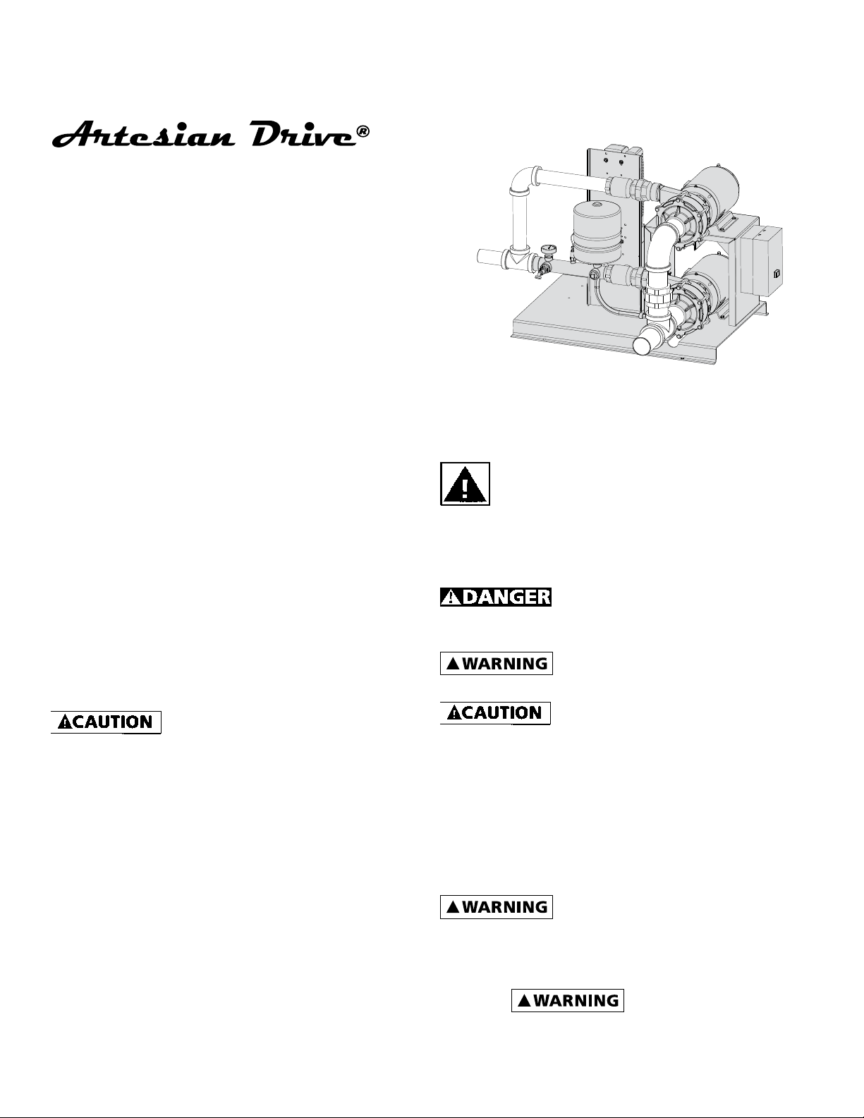
KEY FEATURES OF THE ARTESIAN DRIVE PUMP
STATION ADD-ON KIT:
The duplex kit is designed as an add on to the Single
pump Artesian Drive pump station to increase the
capacity of the pumping station without adding an
additional drive. The duplex kit, must match the HP of
the pump station that it is to be added to for proper
operation. When added to the pump station, the single
phase pump will turn on when the drive is running the
three phase pump at full speed and still cannot reach
the system pressure set point. When the single phase
pump is running, depending upon demand, the drive
may shut off the 3-phase pump. After the single phase
pump has started and demand decreases, when the
pressure increase to 5 PSI above the set point the drive
will start up the three phase pump again and then shut
down the single phase pump. To reduce the chance of
damage to the single phase pump and motor that can
occur with short cycling, the single phase motor will
remain running for a minimum of 1 minute even if
the system pressure rises above the set point. Once the
single phase motor turns off, it will also remain off for
one minute before it will turn back on even if the pressure drops below the system set point.
If plumbing cannot withstand
maximum pump pressure plus incoming pressure,
a pressure control valve shuld be installed after
the check valve on the single phase pump and set
10 psi above the system pressure set point on the
drive. This will prevent any damage to the system
plumbing in the event a sudden drop in water
demand creates maximum deadhead pressure.
Only shaded areas
included in package
Figure 1
General Safety Information
Carefully read and follow all safety instructions
in this manual and on pump. Keep safety labels in
good condition. Replace missing or damaged safety
labels.
This is a SAFETY ALERT SYMBOL. When you
see this symbol on the pump or in the manual,
look for one of the following signal words and
be alert to the potential for personal injury or
property damage.
Warns of hazards that WILL cause
serious personal injury, death or major property
damage if ignored.
Warns of hazards that CAN cause
serious personal injury or death, if ignored.
Warns of hazards that MAY
cause minor personal injury, product or property
damage if ignored.
IMPORTANT: Indicates factors concerned with
operation, installation, assembly or maintenance
which could result in damage to the machine or
equipment if ignored.
NOTE: Indicates special instructions which are
important but are not related to hazards.
Read these warnings and
instructions carefully. Failure to follow could
result in serious bodily injury and/or property
damage.
Electrical installations
shall be in accordance with National Electric
Code (NEC) and all applicable local codes
and ordinances. A licensed electrician should
1 (FW1442)
95 North Oak St. • Kendallville, IN 46755 • 1-800-742-5044
023507 B
Page 2
perform installation.
!
!
!
!
!
!
!
!
Be sure system is connected to
a circuit equipped with a fuse or circuit breaker of
the correct rating.
Always disconnect power
source before performing any work on or near
the controller, motor or its connected load. If the
power disconnect point is out-of-sight, lock it
in the open position and/or tag it to prevent unexpected
application of power. Failure to do so could result in fatal
electrical shock or bodily injury.
DO NOT handle pump with wet
hands or when standing in water as fatal electrical
shock could occur. Disconnect main power supply
before handling system for any reason.
Protect the power cable from
coming in contact with sharp objects, oil, grease,
hot surfaces or chemicals. DO NOT kink the power
cable. If damaged replace immediately.
NEVER leave the control box,
fused disconnect switch, or covers open (either
partially or completely) when not being worked on
by a competent electrician or repairman.
Always use caution when operating
electrical controls in damp areas. If possible, avoid all
contact with electrical equipment during thunderstorms
or extreme damp conditions.
Install all electrical equipment
in protected area to prevent mechanical damage
which could produce serious electrical shock and/or
equipment failure.
Single Phase Motor Data: Chart A
MODEL HP
C22231H 3
C22251H 5 230V 230V - 27.4 H
C22271H 7-½ 230V 230V - 34.5 H
Minimum Wire Size Charge (Gauge): Chart B
HP Volts Phase
3 115/230 1 8/12 8/12 4/10 4/10 2/8 40/20
5 230 1 8 8 8 8 6 40
7.5 230 1 6 6 6 6 4 50
IMPORTANT: Wire charts are for reference only. Consult local and state codes for approved wire sizes.
MOTOR
VOLTAGE
115/208-
230V
Distance in Feet From Motor To Service Panel
0-50ft 50-100ft 100-150ft 150-200ft 200-300ft
Connected Motor
DO NOT use this system to pump
flammable liquids such as gasoline, fuel oil, kerosene,
etc. Failure to follow the above warning could result in
property damage and/or personal injury.
This product contains chemicals known
to the State of California to cause
cancer and birth defects or other reproductive harm.
Do not pump water above 140 degrees
Fahrenheit.
This unit not tested for use in
swimming pool areas.
Before Getting Started
may result from failure to connect the ground
terminal to the motor, Artesian Drive controller,
metal plumbing, or other metal near the motor
or cable, using wire no smaller than motor
cable wires. To minimize risk of electrical shock,
disconnect power before working on or around
the Artesian Drive system. CAPACITORS INSIDE
THE ARTESIAN DRIVE CONTROLLER CAN STILL
HOLD LETHAL VOLTAGE EVEN AFTER POWER HAS
BEEN DISCONNECTED. ALLOW 10 MINUTES FOR
DANGEROUS INTERNAL VOLTAGE TO DISCHARGE
BEFORE REMOVING ARTESIAN DRIVE COVER.
swimming areas.
Factory
Voltage
230V 32.2 16.1 G
Wire Size
Serious or fatal electrical shock
Do not use motor or system in
Service Factor
Motor Amps
115V 230V
Code
Letter
Breaker Size
(Amps)
Instructions:
ACTIVATE DUPLEX OPTION IN DRIVE:
When the Artesian drive pump station leaves the factory, the default setting it to have the Duplex Mode
turned off. To change settings:
1. Press & release M button to display flashing number on left hand side of display (i.e. 01). Using v &
^ buttons scroll until you reach 10 flashing on left
hand side.
2. Press & release M button and then Press & release &
^ buttons to scroll display to show L3 on right hand
side.
3. Press & release M button and use v & ^ buttons to
scroll until you reach 70 flashing on left hand side.
4. Press & release M button and CodE flashes on the
right hand side. Press & release ^ until Co 3 is displayed.
5. Press & release M button. Using v & ^ scroll the
value between OFF to ON.
6. Press & release M button to return to having 61 on
left of screen flashing. Using v & ^ buttons scroll to
10 flashing on left hand side.
7. Press & release M button then press & release ^ button until LoC is displayed. Press & release M button
twice to return to standard screen.
8. Turn off power to drive & skid system in preparation for mechanical & electrical installation of the
duplex kit.
MECHANICAL INSTALLATION:
• Mount pump support to pump station skid straddling existing pump as shown in Figure 1 using ¼”
bolts, washers & lock washers.
• Mount starter box to side of the pump support with
¼” bolts, nuts, washers & lock washers.
• With help set single phase pump on top of pump
support and secure with 3/8” bolts, nuts, washers &
lock washers.
• Using Teflon tape or pipe dope on the threads,
install a 2” union on discharge of pump and screw
check valve into the union tightening with a
wrench 1-2 turns past hand tight to prevent leaks.
• Note: For suction lift applications, a service T with
a threaded in priming plug should be installed on
the intake pipe of the pump for priming purposes.
If possible for suction lift applications, it is recommended to use a separate drop pipe (not shown
in illustrations) into the water source to allow for
easier priming.
• Plumb with desired 2” piping (not supplied) as show
in Figure 1 from check vale and “T” into discharge
manifold.
Because of the 1 minute minimum
run time of the single phase pump, the system
plumbing & fixtures must be able to withstand
full deadhead system pressure (maximum pump
pressure + incoming PSI). If the plumbing system
cannot handle deadhead pressure, a pressure
control valve needs to be installed after the check
valve installed on the single phase pump and set
6-10 PSI above system pressure set on the drive of
the pump station.
• Note: For serviceability, unions & isolation vales
should be installed to allow replacement of either
pump without disturbing the other.
ELECTRICAL INSTALLATION:
• Install, ground, wire and maintain this installation
in accordance with your local electrical code and all
other codes and ordinances that apply. Consult your
local building inspector for local code information.
All electrical work should be performed by qualified
personnel.
• Ground the starter permanently using a wire of size
and type specified by local or United States National
Electrical Code. Do not ground to a gas supply line.
• Connect ground wire first. Connect to ground first
and then connect ground wire to motor starter
box. Connect starter ground to green grounding
terminal located inside of the motor terminal box.
Ground connection MUST be made to this terminal.
Do not connect motor to electrical power supply
until unit is permanently grounded; otherwise serious or fatal electrical shock hazard may be caused.
• IMPORTANT: Check local and/or United States
National Electric Codes for proper grounding information.
• Power should supplied with a correctly fused disconnect switch to provide protection. Consult Local
or National Electrical Codes for proper fuse protection based on motor nameplate.
• Whenever possible, the pump should be powered
from a separate branch circuit of adequate capacity
to keep voltage drop to a minimum during starting and running. For longer runs, increase wire size
in accordance with the Wire Selection guide. (See
Chart B). IMPORTANT: Wire charts are for reference
only. Consult local and state codes for approved
wire sizes.
• See Figure 4 for wiring from power circuit to starter
and to motor.
• For proper electrical connections to the motor, refer
to the connection diagram located on the nameplate or inside the terminal box of the motor. Make
sure connections are correct for the voltage being
supplied to the motor.
2 (FW1442)
95 North Oak St. • Kendallville, IN 46755 • 1-800-742-5044
95 North Oak St. • Kendallville, IN 46755 • 1-800-742-5044
3 (FW1442)
Page 3

• Install provided heaters onto starter. Note: the heat-
To Properly Protected
ers provide over current protection for the motor.
This starter with heaters installed does not provide
protection from short circuits.
• Connect Starter L1 and Overload relay terminal X2
with wire rated for system power and route enough
wire to connect them to Drive terminals T5 & T6
respectively.
• IMPORTANT: For priming purposes only, temporarily
wire nut the wires together instead of connecting
to T5 and T6. After full prime, connect to T5 and T6.
• Connect Starter L2 to Coil terminal W with wire
rated for system power.
• Install temperature sensor wire provided onto ¼”
quick connect terminals of the temperature sensor
located near the pump discharge (Figure 2) to drive
terminals B2 & B7 (Figure 3) (Note: The new temperature sensor wires will share B2 & B7 drive terminals with factory installed wires.)
Figure 2 Temperature Sensor Location
Operation
Unit must be full of fluid before
operating. Do not run dry, or against a closed
discharge. Do not pump dirty water or abrasive
liquids. To do so will cause pump failure and will
void the warranty.
VALVES
The suction inlet valve should be in the full open position and hose bib valve should be partially open, allowing some back pressure to be exerted against the pump
when starting up. Close hose bib valve after priming up
is completed.
PRIMING
IMPORTANT: Before starting the pump it is absolutely
necessary that both pumps and the suction pipe be
completely filled with water. Before the entire duplex
pump system is fully operational, the single phase
pump, needs to be completely primed and run before
returning power to the variable frequency drive.
IMPORTANT: Before priming, verify control wires are
temporarily connected with a wire nut instead of being
connected to drive terminals T5 & T6.
PRIMING OF PRESSURE BOOST INSTALLATIONS
Priming is simple when pump is connected to a pressure
source such as a city main or above ground tank filled
to a level of 4 ft. above pump inlet.
1. Open inlet valves fully on suction and open hose
bib on skid system manifold.
2. To relieve trapped air, allow water supply to run a
minimum of 2 minutes before starting the pump.
3. Turn on power to the single phase pump and run
no longer than two (2) minutes. Unit should build
pressure & pump water. If not, repeat the sequence
above.
4. Once all air has been evacuated and the pump has
been primed, close hose bib and turn off power.
5. IMPORTANT: Once priming has been completed &
power has been turned off, remove the wire nut
connecting control wires and connected them to
drive terminals T5 & T6 (Figure 3).
T6T5T4T3T2T1
Transducer Wire - Black
B1
B4
B3B2
B7B6B5
Transducer Wire - Red
Jumper Wire
Temperature Sensor Wire - Red
Temperature Sensor Wire - Black
1
Transducer Cable
Temperature Sensor Cable
2
Figure 3 Drive Control Circuit Terminals
Starter Control Wires
IL1140
Disconnect Circuit
L1 L2
Motor Starter
Coil Terminals
Line Terminals
L1 L2 L3
Overload Relay
Terminals
Drive
Terminals
Figure 4 Starter Wiring
T5
T6
NC
T1 T2 T3
X2
Starter Control Wires
Install Heaters
Load Terminals
Pump
Motor
IL1139
PRIMING FOR SUCTION LIFT INSTALLATIONS
On suction lift applications prime the unit as follows:
1. Remove priming plug from service tee and fill pump
and suction pipe with water.
2. Jog the pump motor by applying power on and off
several times to free air trapped inside the pump.
3. After jogging the pump, refill with water and
repeat the priming sequence several times to be
sure all air is out of the pump and suction pipe.
4. Open hose bib on skid system manifold, start the
pump and run no longer than two (2) minutes. Unit
should build pressure & pump water. If not, repeat
the sequence above.
NOTE: On first use of pump, it may be necessary to reprime the unit three (3) or four (4) times before all air is
out of the suction pipe.
5. Once all air has been evacuated and the pump has
been primed, close hose bib and turn off power.
6. IMPORTANT: Once priming has been completed &
power has been turned off, remove the wire nut
connecting control wires and connected them to
drive terminals T5 & T6 (Figure 3).
START-UP PROCEDURE
Once the preceding instructions have been completed,
the entire system can be started:
1. Verify that all values installed on the intake side of
the pumps are open & the isolation value is closed
if installed on the discharge side of the system.
2. Verify that the 3-phase pump is primed. For gravity
fed systems, this can be accomplished by opening
hose bib valve installed on the system manifold to
allow the water pressure to push out the air from
the pump. For suction lift systems, fill the pump
and intake piping with external water source until
water begins coming out the open hose bib valve.
3. Close hose bib valve.
4. Supply electrical power to Pump Station by turning
on the user installed disconnect to the ON position
and allow system to pressurize and check for leaks
on plumbing installed.
5. Once pressure has been established, partially crack
open the station isolation valve (while maintaining
pressure) and open valves farthest away from pump
station to bleed air out of the system & piping
6. When the whole Main Line has been bled of air,
fully open the discharge isolation valve.
7. Supply electrical power to single phase pump by
truing on the user installed disconnect to the ON
position. When demand exceeds the capacity of the
three phase pump, the single phase motor will start
up for a minimum of one minute.
8. During the first few hours of operation, inspect the
pump, piping and any auxiliary equipment used in
connection with the unit.
9. Check for leaks, excessive vibration or unusual
noises.
MAINTENANCE:
For proper maintenance of the pump, please follow
instructions in enclosed End suction centrifugal pumps
instructions FW0300/134984.
4 (FW1442)
95 North Oak St. • Kendallville, IN 46755 • 1-800-742-5044
5 (FW1442)
95 North Oak St. • Kendallville, IN 46755 • 1-800-742-5044
Page 4

Troubleshooting Chart
Symptom Possible Cause(s) Corrective Action
Low or no discharge 1. Incorrect rotation 1. Refer to wiring diagram
2. Insufficient inlet pressure or
suction head (NPSH Required)
3. Total head too high 3. Lower discharge head
4. Leak in suction line 4. Repair or replace
5. Impeller clogged or damaged 5. Clean or replace
6. Wrong size piping 6. Make needed adjustments
7. Casing gasket leaking 7. Replace gasket
8. Suction or discharge line valves
closed
9. Mechanical seal leaking 9. Replace
Loss of suction 1. Insufficient inlet ressure or suction
head (NPSH Required)
2. Clogged strainer 2. Clean or replace
Pump vibrates and/
or makes excessive
noise
Pump leaks at shaft 1. Damaged or worn mechanical seal 1. Replace
Pump will not start
or run
Motor problems 1. Various 1. Consult qualified electrician
Pinholes in the
casting. Liquid
dripsp around seal
area but is not seal
1. Mounting plate or foundation not
rigid enough
2. Foreign material in pump 2. Clean
3. Damaged impeller 3. Replace
4. Cavitation present 4. Check suction line for proper size and be sure
2. Corrosion due to character of
liquid pumped
1. Improperly wired 1. Refer to wiring diagram
2. Blown fuse or open circuit breaker 2. Replace fuse or close circuit breaker
3. Loose or broken wiring 3. Tighten connections and replace broken wiring
4. Impeller clogged 4. Clean
5. Motor shorted out 5. Replace
2. Overloading motor. Too much
water delivery
3. Liquid heavier and more viscous
than water
4. Seal binding 4. Replace
5. Rotor binding 5. Repair or replace
6. Voltage and frequency lower than
rating
7. Defects in motor 7. Repair or replace
1. Cavitation caused by insufficient
inlet pressure or suction head
(NPSH Required)
2. Increase inlet pressure by adding more fluid to
fluid source. (See Spec’s for minimum NPSH
Required)
8. Open
1. Increase inlet pressure by adding more fluid to
fluid source. (See Spec’s for minimum NPSH
Required)
1. Reinforce
valve is open. Remove excessive loops in suction
line. (See Spec’s for minimum NPSH Required)
2. Discontinue pumping liquid and consult factory
2. Restrict outlet by closing down valve in discharge
line
3. Consult factory
6. Reconnect to rated voltage and frequency
1. Increase inlet pressure by adding a higher level of
fluid to source or increasing inlet pressure. (See
Spec’s for minimum NPSH Required)
CONTINGENCY OPTIONS
For some applications, a contingency plan is needed
if the system is unable to deliver the required water
in the event of a component failure which causes one
pump to fail. The contingency plans below will allow
the working pump to deliver water until the failed
component is repaired/replaced, even if the single
pump cannot meet the pressure demands required by
the application.
1. Problem: Single phase pump or starter failure.
Effect: Single phase pump does not run when
demand is reached. Drive continues to run 3-phase
pump, but system drops below set pressure when
demand is high. User Contingency action: None.
Long term user action: Repair/replace failed single
phase component.
2. Problem: Three Phase pump failure (drive not
tripped on fault). Effect: Three phase pump does
not run. Single phase motor is controlled by the
drive and runs 1 minute on, 1 minute off on low
water demand or continuously with higher demand.
User Contingency action: None. Long term user
action: Repair/replace failed 3-phase pump.
3. Problem: Drive fails. Effect: Neither pump runs.
User Contingency action: With power turned off to
both drive and single phase motor, remove control
wires from drive terminals T5 & T6 and wire nut
together. Hook up a hose to hose bib and route
back to supply tank or drain and open hose bib
valve. (This is done to guarantee a minimum flow of
water thought the pump when there is no demand
for water and prevent damage to the pump that
can occur when the pump is run deadhead.) Turn
power on to single phase pump – Note: Pump will
run continuously. Long term user action: Replace
drive.
4. Problem: Transducer Fails (Drive Trips tr cL1). Effect:
Neither pump runs. User Contingency action: With
power turned off to both drive and single phase
motor, remove control wires from drive terminals T5
& T6 and wire nut together. Hook up a hose to hose
bib and rout back to supply tank or drain and open
hose bib valve. (This is done to guarantee a minimum flow of water thought the pump when there
is no demand for water and prevent damage to the
pump that can occur when the pump is run deadhead.) Turn power on to single phase pump – Note:
Pump will run continuously. Long term user action:
Replace transducer.
6 (FW1442)
95 North Oak St. • Kendallville, IN 46755 • 1-800-742-5044
7 (FW1442)
95 North Oak St. • Kendallville, IN 46755 • 1-800-742-5044
Page 5

8 (FW1442)
95 North Oak St. • Kendallville, IN 46755 • 1-800-742-5044
 Loading...