

Page 1
COMMANDER PRO 75
COMMANDER PRO 100
COMMANDER PRO 150
Constant Pressure Water Systems
Owners Guide to Installation and Operation
WARNING
IMPORTANT SAFETY INSTRUCTIONS
RULES FOR SAFE INSTALLATION AND OPERATION
1. Read these warnings and instructions carefully.
Failure to follow them could cause serious bodily
injury and/or property damage.
2. Follow all local electrical and safety codes as well
as the National Electrical Code (NEC) and the
Occupational Safety and Health Act (OSHA).
3. The power supply should be a separate circuit,
independent of all other circuits. Be sure it is
equipped with a fuse and disconnect box of ample
capacity.
4. For fire protection, the power supply should be free
of any building, preferably on a direct line from the
transformer. In the event of fire, the wires will not be
destroyed and the water supply not cut-off.
5. Always disconnect power source before performing
any work on or near the motor or its connected load.
If the power disconnect point is out-of-sight, lock it in
the open position and tag it to prevent unexpected
application of power. Failure to do so could result in
fatal electrical shock.
6. DO NOT handle pump with wet hands or when
standing in water as fatal electrical shock could occur.
Disconnect main power supply before handling pump
for any reason.
7. Shut off power source when voltage drops 10% below
the rated voltage of the motor.
8. Protect the power cable from coming in contact with
sharp objects, oil, grease, hot surfaces or chemicals.
DO NOT kink the power cable. If damaged replace
immediately.
9. NEVER leave the control box, fused disconnect
switch, or covers open (either partially or completely)
when not being worked on by a competent electrician
or repairman.
10. Always use caution when operating electrical controls
in damp areas. If possible, avoid all contact with
electrical equipment during thunderstorms or extreme
damp conditions.
11. Install all electrical equipment in protected area to
prevent mechanical damage which could produce
serious electrical shock and/or equipment failure.
12. Pump is designed to pump cold ground water that is
free of air or gases. Decreased pump performance
and life expectancy can occur if the ground water is
not cold (86°F/30°C) or contains air or gases.
13. Pump and controls must be securely and adequately
grounded as specified in section 250-43 item (A) of
the U.S.A. National Electric Code (NEC) and Section
26-954 Canadian Electrical Code. Failure to do so
could result in a fatal injury.
14. DO NOT use this pump to pump flammable liquids
such as gasoline, fuel oil, kerosene, etc. Failure to
follow the above warning could result in property
damage and/or personal injury.
The pump is intended for use in a well.
Motor frame must be connected to power supply ground or
fatal electrical shock may result. Do not use this pump in
swimming pools.
15. Capacitors inside CP WATER
Subdrive controllers can still hold a lethal voltage
even after power has been removed. Allow 10 minutes
for dangerous internal voltage to discharge before
operating the unit.
16. Use of this unit with motors from
other manufacturers may result in damage to both
motor and electronics.
17. Do not use power factor correction
capacitor with the CP WATER Subdrive. Damage
will result to both motor and electronics.
NOTE: Pumps with the “CSA” mark are tested to UL
standard UL778 and certified to CSA standard C22.2 No.
108.
95 North Oak Street • Kendallville, IN 46755
1
Copyright 2012. All Rights Reserved.
023802 A
Page 2
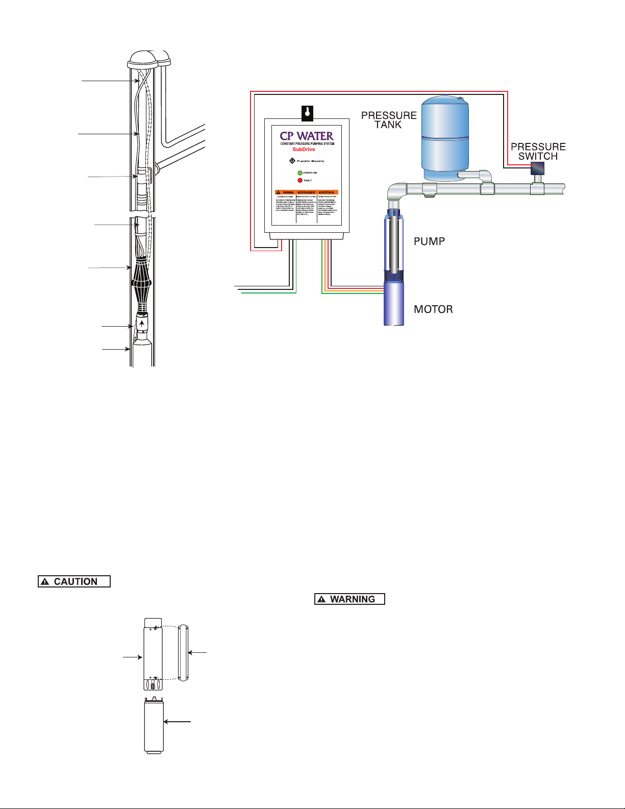
Typical Installation
Submersible
Cable
Riser
Pipe
Pitless
Adapter
Plastic or
Steel Pipe
Torque
Arrestor
Check Valve
Submersible
Pump
Figure 1 — Typical Installation with Pre-Charged Tank
Conduit
IL00074
READ THESE INSTRUCTIONS COMPLETELY BEFORE INSTALLATION
1. Check that the pump and motor mounting faces are
free from dirt.
2. Assemble the pump liquid end and motor together
so that mounting faces are in contact. Then tighten
assembly bolts evenly in a crossing pattern.
NOTE: Apply non-toxic FDA approved waterproof grease
such as Mobile 102, Texaco CYGNUS2661 or equivalent
to the coupling before assembly of pump coupling to
motor shaft. This will prolong spline life and prevent
abrasives from entering the spline area.
3. Check for free rotation of the pump and motor. A
slight drag is permissible.
4. Assemble the pump lead guard over the motor leads.
Do not cut or pinch lead wire during
assembly.
5. Assemble suction screen to pump mounting ring.
Liquid
End
IL0094B
FIGURE 2
Lead Wire
Guard
Motor
95 North Oak Street • Kendallville, IN 46755
Copyright 2012. All Rights Reserved.
NEMA 1 SYSTEM
ONLY
Not supplied
with “LT” Models
PRESSURE RELIEF
VALVE
PRE-INSTALLATION
To save possible added expense and extra trips, observe
and complete as many as possible of the following
precautions and pre-installation procedures before going
to the job site or beginning the installation.
IMPORTANT PRECAUTIONS
1. Prior to installation, inspect the pump for damage.
Check for free pump and motor rotation. A slight drag
is permissible.
2. Check to make certain that the voltage of the motor
end and controls agree with the available phase
and voltage. Check power source. Check electrical
supply for correct fusing, correct wire size, and
adequate grounding and transformer size.
Since most submersible pump problems
are electrical, it is very important that all electrical work
be done properly. Therefore, all electrical hook-up work
or electrical service work should be done by a qualified
electrician or service man only!
3. Throughout installation, take care not to damage
the insulation of the electrical cable or motor leads.
Never support the weight of the unit by electrical cable
or motor leads.
4. Before the pump is installed, the well should be
pumped free of sand and other foreign matter with
a test pump. The warranty is void if it is used to
clean the well.
2
Page 3
MAJOR WELL COMPONENTS
1. Submersible Pump — A submersible pump is a multistage centrifugal. Each stage consists of an impeller
and diffuser. Water pressure increases in equal
amounts as it passes from stage to stage. The more
stages, the higher the pressure the pump will develop.
2. Submersible Motor — The submersible motor is
powered by three phase electricity. Make sure the
motor is designed for three phase operation.
3. Subdrive Controller — Subdrive is designed for use
in residential and light commercial applications with a
3-phase submersible motor using single-phase input.
Motor Design Designation
Subdrive 75 Controller 1-1/2 HP
Subdrive 100 Controller 2 HP
Subdrive 150 Controller 3 HP
This variable speed controller can be used to provide
constant pressure delivery over a wide range of
settings (25 to 80 PSI). Factory preset is 50 PSI.
4. The Well — The well should be sand free and have a
sufficient flow of water to supply the pump. Clear well
of sand and any other foreign matter with a test pump
before installing the new submersible pump.
Using the submersible pump to clean the
well will void the warranty.
a. When drilling a new well in an area where sand is
a problem, a sand screen should be installed to
protect the pump and motor.
b. The well should be straight so damage during
installation does not occur to the pump or motor by
becoming lodged in a crooked well casing.
c. The complete pump and motor should be
submerged at least ten feet below the draw
down level of the well, and the motor should be a
minimum of ten feet off the bottom of the well.
5. The Piping — Install the pump with pipe of the same
diameter as the discharge port of the pump or larger.
NOTE: Use of pipe smaller than the discharge port of the
pump will restrict the capacity of the pump and lower its
operating performance.
6. Check Valve — A check valve is required on all
submersible installations. This valve maintains water
within the pipe when the pump is not running. A line
check should be installed within 25 feet of the pump
and below the draw down level of the water supply.
a. For well depths exceeding 200 feet, it is suggested
that an additional check valve be installed every
125 feet.
b. An additional check valve should be installed in the
horizontal line between the well top and the pressure
tank.
Make certain that the check valve is
pointing in the right direction, arrow pointing towards the
tank.
7. Torque Arrester — To center the pump as it is
being lowered into the well, a torque arrester is
recommended.
8. Pressure Tank — Any change to operating system
pressure will require that the precharge in the tank be
modified to 70% of that pressure.
Pressure Setting Guide
System Pressure
(at Pressure Sensor)
Pressure Tank Setting
(PSI) (+/- 2 psi)
25 18
30 21
35 25
40 28
45 32
50 (factory set) 35
55 39
60 42
65 46
70 49
75 53
80 56
Required Tank Size
10 gpm and smaller 19 gpm and larger
CP75 2 gallons 4 gallons
CP100 4 gallons 8 gallons
CP150 4 gallons 8 gallons
9. Pressure Relief Valve — The pressure relief valve and
the discharge outlet need a flow rating which exceeds
the flow capacity of the installation at the relief
pressure. When located in an area where a water leak
or relief valve blow-off may damage property, connect
an adequate drain line to the pressure relief valve.
Run the line to a suitable drain or to an area where
the water will not damage property.
Not providing an adequate relief valve
can cause extreme overpressure which could result in
personal and/or property damage. It is recommended that
you manually activate the valve monthly to keep it in good
working condition.
10. Pitless Adapter — A pitless adapter provides below
grade discharge while maintaining above grade
access to the well. Placed below the frost line they
are frost proof and also prevent well contamination by
providing a water tight seal between the vertical drop
pipe and the horizontal service pipe connection.
11. Well Seal — On well seal installations the piping in
the well projects above the well and is connected
above ground to the system piping by means of a tee
or elbow. Since the plumbing is above ground, it must
be protected from freezing.
12. Submersible Cable — Submersible power cable must
be UL listed for submersible pump application. Selecting
the proper cable size is important. Undersized cable
results in a too low voltage supply to the pump motor
95 North Oak Street • Kendallville, IN 46755
Copyright 2012. All Rights Reserved.
3
Page 4

and ultimate motor failure. Oversized cable is costly and
not necessary. Refer to cable selection chart for proper
cable selection. Cable is selected for the maximum
pump setting plus the offset distance to the service
entrance.
13. Ground Wire — The National Electric Code (NEC 250-
43) requires a separate ground wire be run down the
well to the submersible pump and to be connected to
all exposed metal parts of the pump and motor. Refer
to the most recent National Electric Code (NEC) for
additional grounding information. All wiring should be
done by a competent electrician.
INSTALLATION
SUBMERSIBLE CABLE INSTALLATION
1. Check power source. Check electrical supply for
correct fusing, correct wire size, and adequate
grounding and transformer size.
Since most submersible pump problems
are electrical, it is very important that all electrical work
be done properly. Therefore, all electrical hook-up work
or electrical service work should be done by a qualified
electrician or serviceman only!
2. Follow wiring directions in installation and operations
manual.
3. Check cable size against the Submersible Wire Size
Chart. Use extreme care; this is a very important
step. If required length falls between two wire sizes,
use the larger of the two wire sizes (smaller number).
IMPORTANT: Use of wire sizes smaller than those
specified in the charts will cause low starting voltage,
may cause early pump failure and will void the warranty.
Larger wire sizes may always be used for better operating
economy.
Maximum wire lengths connecting the motor to the controller
Subdrive
Subdrive 75 Maximum Length (Ft.) 420 670 1060 1670 -
Subdrive 100 Maximum Length (Ft.) 320 510 810 1280 2010
Subdrive 150 Maximum Length (Ft.) 240 390 620 990 1540
4. Splice motor leads to submersible cable with
commercially available potting, heat shrink splicing
kits or by careful tape splicing. Tape splicing should
use the following procedure.
Copper Wire size
(AWG)
Staked Connector
2” 2”
2” 2”
14 12 10 8 6
Rubber Tape
a) Strip individual conductor of insulation only as far
as necessary to provide room for a stake type
connector. Tubular connectors of the staked type are
preferred. If connector OD is not as large as cable
insulation, build-up with rubber electrical tape.
b) Tape individual joints with rubber electrical tape,
using two layers; the first extending two inches
beyond each end of the conductor insulation end,
the second layer two inches beyond the ends of the
first layer. Wrap tightly, eliminating air spaces as
much as possible.
c) Tape over the rubber electrical tape with #33
Scotch electrical tape, (Minnesota Mining Co.)
or equivalent, using two layers as in step “b” and
making each layer overlap the end of the preceding
layer at least two inches.
5. In the case of a cable with three conductors encased
in a single outer sheath, tape individual conductors as
described, staggering joints. Total thickness of tape
should be less than the thickness of the conductor
insulation.
GROUND WIRE INSTALLATION
Motor frame must be connected to power
supply ground or fatal electrical shock may result.
NOTE: All electrical wiring should be done by a
competent electrician.
1. Grounding the submersible pump is accomplished by
running a copper grounding wire from the pump motor
to the main electrical system ground.
2. The ground wire to be used must be of the same size
as the submersible power cable. It may be insulated
or bare. If insulated, it must be green, with or without
yellow stripe(s). The ground wire may be part of, or
separate from, the supply cable. It may be continuous
or spliced above the pump along with the supply
cable.
3. The motor lead wire assembly includes a green
insulated ground lead. Splice the ground wire to the
green insulated lead.
4. The other end of the ground wire will be connected to
the power supply grounding terminal or to the control
panel ground bar if it is connected to the power supply
ground.
NOTE: See section entitled Grounding for detailed
grounding instructions.
INSULATION AND CONTINUITY TEST
1. It is recommended that this test be done when the
splicing is complete and pump is being test run in
a tank of water. This test can be repeated after
installation in well but before the final electrical hookup is made to the control box or pressure switch.
IL0097
Figure 3
PVC Electrical Tape
4
95 North Oak Street • Kendallville, IN 46755
Copyright 2012. All Rights Reserved.
Page 5

IL0098
IL0099
Figure 4
2. Zero the ohmmeter by clipping the leads together and
adjusting the zero ohm knob until the needle indicates
zero. Zero the ohmmeter before each use or every
time selector switch is changed.
3. Clip one ohmmeter lead to bare cable end.
4. Clip the other lead to edge of steel tank in which
pump and cable are submerged. If pump is already in
the well, clip lead to discharge pipe metal well casing
or bare ground wire.
5. A reading of less that 1,000,000 ohms indicates that
cable or splice is grounded. Slowly raise cable from
the water at the ohmmeter end. When trouble spot
moves clear of the water, needle will move toward
infinity reading. In an old installation with the pump in
the well, a reading of 20,000 ohms or less indicates
a breakdown in the insulation; in this case pull the
pump.
PUMP INSTALLATION
1. The following pump installation instructions use
Schedule 80 PVC pipe or galvanized pipe. If either
of these two types are used, a foot clamp or vise will
be required to hold the PVC or galvanized pipe when
connecting the next pipe length.
2. Install the pump in a well which is sand-free, straight,
and has sufficient flow of water to supply the pump.
Clear well of sand and any other foreign matter with a
test pump before installing the submersible pump.
95 North Oak Street • Kendallville, IN 46755
Copyright 2012. All Rights Reserved.
NOTE: Using the submersible pump to clean the well will
void the warranty. When drilling a new well in an area
where sand is a problem, a sand screen must be installed
to protect the pump and motor.
3. Chlorinate the well first. Drop 24 to 48 HTH (chlorine)
tablets into the well before lowering the pump into the
well. This will prevent contamination and the growth
of iron bacteria which could later plug the well and the
pump. The chlorinated water will be pumped out of
the system when testing the pump flow.
4. BE SURE the top edge of the well casing is perfectly
smooth; sharp or jagged edges can cut or scrape the
cable and cause a short.
5. Install a line check valve within 25 feet of the pump
and below the draw down level of the water supply.
The check valve should be the same size as the
discharge outlet of the pump or larger.
NOTE: Use of pipe smaller than the discharge tapping of
the pump will restrict the capacity of the pump and lower
its operating performance.
6. When connecting the first length of pipe and
placing the pump in the well casing, care should be
maintained to center the pump in the well. It is easier
to handle the pump if a short piece of pipe is installed
first, rather than a long piece. Install the check valve
at the end of the first piece of pipe prior to lowering
the pump into the well. Maintain alignment as the
pump is placed and lowered into the well, a torque
arrester is recommended to keep the pump centered
in well. Wrap the pipe with enough tape at top and
bottom of torque arrestor to keep it from sliding up the
pipe while the pump is being lowered into the well.
7. If not already done, splice the electrical cable to the
motor leads. The cable and ground wire should be
taped to the discharge pipe. Tape the cable about 5
feet above the discharge and every 20 feet thereafter.
Install cable guards if required to eliminate rubbing
against the well casing. Do not let the cable drag over
the edge of the well casing. Never allow the weight of
the pump to hang on the cable alone.
8. Lower the pump into the well slowly without forcing.
Use a vise or foot clamp to hold the pipe while
connecting the next length. A boom, tripod or
pump setting rig is recommended. Lower pump to
approximately 10 feet below maximum draw down of
the water if possible and keep approximately 10 feet
from the bottom. DO NOT set pump on bottom of
well. Before each new length of pipe is added, attach
the coupling to the top of the pipe length. This will
provide a stop for the foot clamp to hold while the next
section of pipe is being installed.
WELL SEAL/PITLESS ADAPTER INSTALLATION
1. All installations should have a well seal. Make sure
the seal is seated and tighten the bolts evenly.
NOTE: Be sure to assemble the tee to the pipe above
the well seal to prevent dropping the pipe and pump down
the well as you lower it.
5
Page 6

IMPORTANT: Well seal and piping must be protected
SEPARATED WIRE
from freezing.
2. On a pitless adapter installation, the connection to the
system supply line is made below ground. Install the
pitless adapter following the instructions included with
particular brand or design being used in the installation.
NOTE: Follow ALL applicable state and local plumbing
codes.
PRELIMINARY TEST RUN
1. When pump is at desired depth, install throttle valve
for preliminary test run. Test cable for continuity with
an ohmmeter.
2. With pump discharge throttled, run pump until water is
clear of sand or any other impurities. Gradually open
discharge.
Be sure you do not stop pump before
water runs clear. This may take several hours. If pump
stops with sand in it, it will lock.
3. If pump lowers water in the well far enough to lose
prime lower pump in the well.
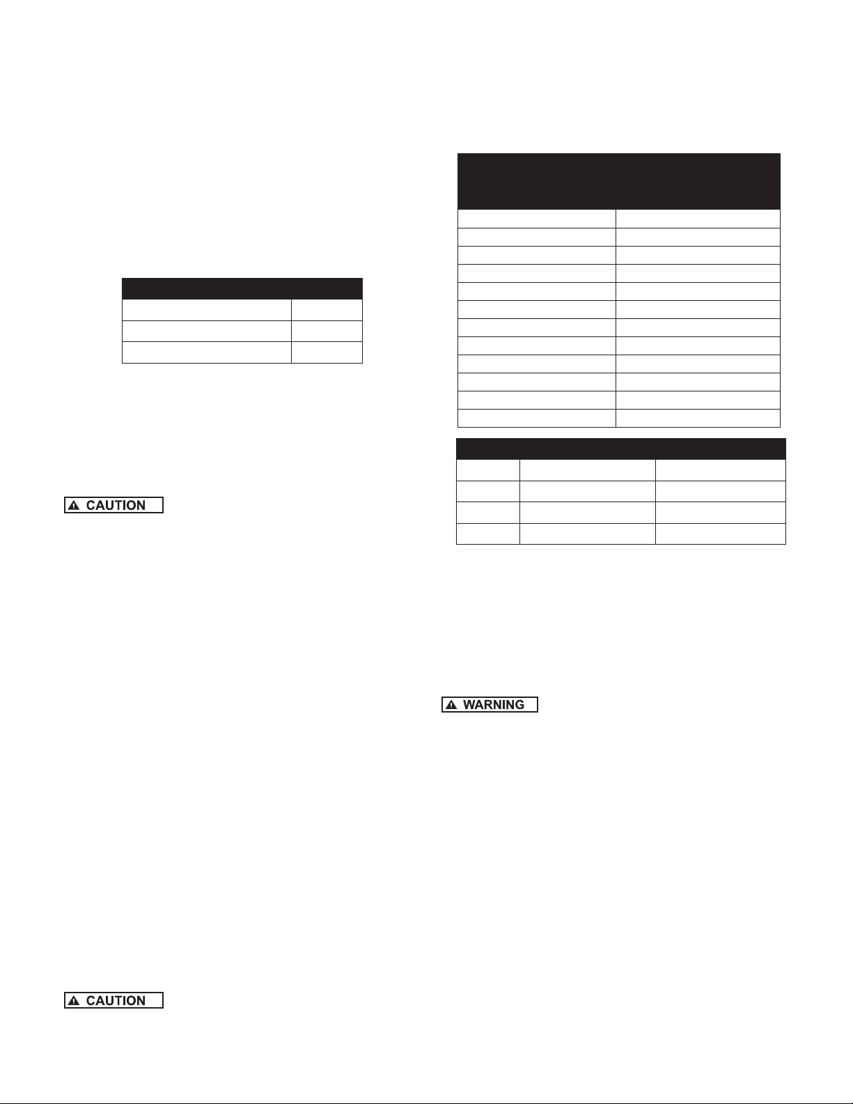
CONTROLLER LOCATION SELECTION
The CP WATER Subdrive standard NEMA 1 controller
is intended for indoor use and for operation in ambient
temperatures up to 125° F (50° C) at rated input voltage.
For outdoor installations, a system with a NEMA 4
rated controller must be used. (Models with 8th and
9th characters of “N4”). To ensure maximum weather
protection, the unit must be mounted vertically with the
cover properly aligned and secured with all lid screws.
The following recommendations will help in selection of
the proper location of the CP WATER Subdrive 100 unit:
1. A tank tee is recommended for mounting the tank,
pressure sensor, pressure gauge, and pressure relief
valve at one junction. If a tank tee is not used, the
pressure sensor should be located within 6 ft. (1.8
meters) of the pressure tank to minimize pressure
fluctuations. There should be no elbows between the
tank and pressure sensor.
2. The unit should be mounted on a sturdy structure such
as a wall or supporting post.
Unit Weight
Model NEMA 1 NEMA 4
Subdrive 75 15.0 lbs. 24.14 lbs.
Subdrive 100 17.5 lbs. 28.32 lbs.
Subdrive 150 17.5 lbs. 28.32 lbs.
CORRECT INCORRECT
Power Supply
From Circuit Breaker
Wiring
Pressure
Sensor Wiring
Power Supply
From Circuit Breaker
Wiring
To Motor
To Motor
Pressure
Sensor Wiring
IL0877
Figure 5
5. The mounting location should have access to 230V,
electrical supply and to the submersible motor wiring.
WIRING
Maximum wire lengths connecting the CP controller
Subdrive
Subdrive 75Max.
Subdrive
100
Subdrive
150
*Wire with 90°C insulation only.
Copper
Wire size
Length (Ft.)
Length (Ft.)
Length (Ft.)
characteristics of variable frequency drives (VFD), there
is additional stress placed on the insulation of the wire
between the controller and the motor compared to a
standard pump system. Extra care must be taken when
using Unjacketed Flat Parallel Pump Cable to ensure that
the insulation on each of the separated wires is the same
thickness. Care must also be taken to ensure a proper
seal with shrink tubing on any splices. Failure to take
these precautions can lead to “wire burn through” that
will shut down the system. Under these circumstances,
no permanent damage usually occurs to the controller or
motor. For further details call Technical Support at
1-800-742-5044.
to the main circuit box
(AWG)
Max.
Max.
14 12 10 8 6 4 3 2
85 135 225 345 550 865
85* 140* 220 345 550 680 895
115* 180 285 455 560 740
Due to the inherent voltage changing
3. The electronics inside the CP WATER Subdrive are
air-cooled. Allow room for air flow when installing.
There should be at least six inches of
clearance on each side and below the unit to allow room for
airflow.
4. The CP WATER Subdrive should only be mounted
with the wiring end oriented downward. The
controller should not be placed in direct sunlight or
other locations subject to extreme temperatures or
condensation).
95 North Oak Street • Kendallville, IN 46755
Copyright 2012. All Rights Reserved.
Figure 6
NOTE: DO NOT USE ALUMINUM WIRE.
6
Page 7

INSTALLATION PROCEDURE
1. Disconnect electrical power at the main breaker
2. Drain the system (if applicable)
3. Install pressure sensor. The pressure sensor has a
1/4-18 National Pipe Thread (NPT) connection.
4. Use Figure 7 as a guide to locating drill holes into
the wall. Remove the CP WATER Subdrive cover by
removing the three lid screws. Install the unit to the
wall using the three mounting screws (not included).
WIRING CONNECTION
Serious or fatal electrical shock may
result from failure to connect the ground terminal to the
motor, CP WATER Subdrive controller, metal plumbing or
other metal near the motor or cable, using wire no smaller
than motor cable wires. To minimize the risk of electric
shock, disconnect power before working on or around the
CP WATER Subdrive system.
CAPACITORS INSIDE THE CP
WATER SubDrive CONTROLLER CAN STILL HOLD A
LETHAL VOLTAGE EVEN AFTER POWER HAS BEEN
DISCONNECTED.
ALLOW 10 MINUTES FOR DANGEROUS
INTERNAL VOLTAGE TO DISCHARGE BEFORE REMOVING
CP WATER COVER.
DO NOT USE MOTOR IN SWIMMING AREA.
1. Verify that the power has been shut off at the main
breaker.
2. A circuit breaker must be availalbe for the Subdrive.
Wire from the supply panel to the Subdrive must be the
correct size.
Model
Circuit
Breaker
Wire Size
Subdrive 75 15-Amp 14 AWG or larger
Subdrive 100 20-Amp 12 AWG or larger
Subdrive 150 25-Amp 10 AWG or larger
3. Remove the CP WATER Subdrive lid.
4. Feed the motor leads through the opening on the
bottom right side of the unit and connect them to the
terminal block positions marked (green ground wire),
Red (Black) Yellow (Brown) and Black (Blue).
5. Feed the 230V power leads through the large opening
on the bottom left side of the CP WATER Subdrive
controller and connect them to the terminals marked
L1, GND, and L2.
6. Feed the pressure sensor leads through the smaller
opening on the bottom left side of the CP WATER
SubDrive unit and connect the red and black leads to
the terminals marked “1” and “2” (interchangeable) with
a small screwdriver (provided).
7. Use the appropriate strain relief or conduit connectors.
8. Replace the cover. Do not over-tighten the screws.
9. Connect the other end of the pressure sensor cable
with the two spade terminals to the pressure sensor.
The connections are interchangeable. (Figure 8)
From
Power
Source
L1 L2
(Input)
2
Red
Black
1
Mounting
Screw
Location
Power Supply
From Circuit Breaker
CP Water Controller
Mounting Screw Location
CONSTANT PRESSURE PUMPING SYSTEM
SubDrive
POWER ON
FAULh
2
1
Output
To Motor
Red Yel Blk
(Blk)(Brn) (Blu)
(Output)
Mounting
Screw
Location
Pump
Motor
Pressure
Drain
Valve
Sensor
Pressure Tank
Inflation Valve
Pressure Tank
Pressure
Gauge
*Pressure
Relief Valve
To Discharge
To
Residence
Figure 7
IL0878
7
95 North Oak Street • Kendallville, IN 46755
Copyright 2012. All Rights Reserved.
Page 8

10. Set the pressure tank pre-charge at 30% below the
desired water pressure setting (as per the table on
Page 3). To check the tank’s pre-charge, de-pressurize
the water system by opening a tap. Measure the tank
pre-charge with a pressure gauge at its inflation valve
and make the necessary adjustments.
Remove Rubber End Cap To Adjust Pressure
With 7/32" Allen Wrench
Pressure
Sensor
Boot
IL0326
Figure 8
A 10 foot section of cable is provided with the
CP WATER to connect to the pressure sensor.
Lengths of up to 100 feet can be used, provided the
appropriate shielded cabling is used. Consult the
factory for proper cable specification.
11. The pressure sensor communicates the system
pressure to the CP WATER SubDrive controller. The
sensor is preset at the factory to 50 PSI, but can be
adjusted by the installer using the following procedure:
A. Remove the rubber end-cap (Figure 8).
B. Using a 7/32” Allen wrench (provided), turn the
adjusting screw clockwise to increase pressure
and counter-clockwise to decrease pressure. The
adjustment range is between 25 and 80 PSI (1/4
turn = approximately 3 PSI).
C. Replace the rubber end cap.
D. Reset the pressure tank pre-charge to the
appropriate pressure.
When increasing the pressure, do not
exceed the mechanical stop on the pressure sensor or 80
PSI. The pressure sensor may be damaged.
12. Cover the pressure sensor terminals with the rubber
boot provided (Figure 8).
START-UP OPERATION
Apply power to the controller. A steady green light
indicates that the CP WATER SubDrive has power
but the pump is not running. The green light will flash
continuously when the pump is running.
NOTE: Conventional private water systems intermittently
fill a pressure tank as commanded by a standard pressure
switch (e.g. 30-50 PSI). The CP WATER SubDrive
maintains a constant pressure at the pressure sensor
up to the maximum capability of the motor and pump.
Although the pressure is constant at the pressure sensor,
pressure drops may be noticeable in other areas of the
home when additional taps are opened. This is due to
limitations in the plumbing and will be more pronounced
the further the taps are from the pressure sensor. This
would be true of any system, and if observed, should not
be interpreted as a failure in the performance of the CP
WATER SubDrive.
95 North Oak Street • Kendallville, IN 46755
Copyright 2012. All Rights Reserved.
8
Page 9

SYSTEM TROUBLESHOOTING
The built-in diagnostics will protect the system against an application or system problem. The red “FAULT” light on
the front of the CP WATER SubDrive controller will flash a given number of times to indicate the nature of the fault. In
some cases the system will shut itself off until corrective action has been taken. Fault codes and the recommended
corrective action for each are listed in the following table.
# of Flashes Fault Possible Cause Corrective Action
1 Motor under
load
2 Under voltage Low line voltage. Check the loose connection. Check the line voltage.
3 Locked pump Motor/pump is misaligned. Abra-
4 Not used
5 Open circuit Loose connection, defective mo-
6 Short circuit Defective cable, splice or motor. Check motor wiring. Cycle input power * to reset.
7 Overheated
controller
* Cycle input power means, turn the power off and until both lights fade off and apply power again.
Over pumped or dry well. Worn
pump. Broken motor shaft.
Blocked pump or screen.
sive/sand bound pump.
tor or cable.
High ambient temperature. Direct
sunlight. Obstruction of airow.
Wait for well to recover and automatically reset timer to
time out. If the problem does not correct, check motor
and pump. See description on “Smart Reset” at the end
of this document.
Report low voltage to power company. Unit will start
automatically when proper line voltage will restore.
See “Extended Input Voltage Range” at the end of this
document.
Unit will attempt to free a locked pump. If unsuccessful,
check the motor and pump.
Check motor wiring. Make certain all connections are
tight. Make certain proper motor is installed. Cycle input
power * to reset.
This fault automatically resets when the temperature
returns to safe level.
TROUBLESHOOTING GUIDE
Symptom Possible Cause Corrective Action
Water ow rate is not as
high as expected
Excessive pressure
uctuations
Motor runs continuously with no ow demand
from the house
Motor is running backwards Switch two of the three wires leading from the
controller to the motor (3-phase motor)
Temperature in the controller is too high. If
the controller’s heat exchanger becomes too
hot, the controller will reduce the speed of
the pump to lower the pump consumption.
Pump capacity cannot supply demand. Use pump with higher ow rating (if head re-
Lower input line voltage. Check the loose connection. Check the line volt-
Waterlogged tank Check tank for bladder damage-replace if neces-
Pressure tank is too small for ow rating of
the pump.
Leak in pitless adapter. Re-seat the pitless adapter.
Leak in the household plumbing or outdoor
plumbing.
Make sure there is at least six inches of room
around the controller for movement of air.
quirement is still satised).
age. Report low voltage to power company.
sary.
Reset the tank -pre charge. (Should be 70% of
pressure sensor setting.
Use larger tank (8 gal tank minimum).
Check for leaky faucets and pipe ttings and
repair.
95 North Oak Street • Kendallville, IN 46755
Copyright 2012. All Rights Reserved.
9
Page 10

SMART RESET
78
If a motor underload fault condition occurs, the most likely
cause is an over pumped or dry well. To allow the well to
recover, the CP WATER SubDrive will wait 30 seconds
to 5 minutes, determined by duration of the previous run
time, before restarting the motor. For example, the first
time the fault occurs, the CP WATER SubDrive will wait
30 seconds before attempting to restart the pump. If the
system would then run for 1 minute and an underload
fault reoccurs, the controller will wait 4 minutes before
attempting to restart the pump. This schedule allows for
the minimum off-time possible based on the recovery time
of the well.
6.0
5.0
4.0
3.0
2.0
Off Time (Min.)
1.0
0.0
0
123456
Run Time (Min.)
CP Water Pump Underload “Smart Reset”
IL0025
EXTENDED INPUT VOLTAGE RANGE:
The CP WATER SubDrive is designed to provide full
performance with an input supply voltage of 200 to 260V
AC. If the input supply voltage drops below 200V AC,
SubDrive will continue to run at reduced output while
flashing an undervolt warning signal flash code #2. Output
power will continue to decrease with supply voltage until
it reaches the trip level near 130V AC and show flash
code #2. The CP WATER SubDrive will automatically
restart (at reduced output) when the supply voltage rises
to approximately 145VAC. When supply voltage restores
200VAC the undervolt warning signal will stop flashing
and full output performance will resume.
Subdrive 75
Description Part #
Pressure Switch 020627
100 ft. Pressure Switch Cord 020628
4.5 Gal. Tank 020629
Controller - Standard 020143
Controller - NEMA 4 022956
Motor 137458
Pump end for CP7507 CP7507RP
Pump end for CP7510 CP7510RP
Pump end for CP7519 CP7519RP
Pump end for CP7527 CP7527RP
Pump end for CP7535 CP7535RP
Subdrive 100
Description Part #
Pressure Switch 020627
100' Pressure Switch Cord 020628
Controller - Standard 023045
Controller - N4 023046
Motor 2 HP 137462
Pump end for CP10007 CP10007RP
Pump end for CP10010 CP10010RP
Pump end for CP10019 CP10019RP
Pump end for CP10027 CP10027RP
Pump end for CP10035 CP10035RP
Pump end for CP10055 CP10055RP
95 North Oak Street • Kendallville, IN 46755
Copyright 2012. All Rights Reserved.
Subdrive 150
Description Part #
Pressure Switch 020627
100 ft. Pressure Switch Cord 020628
14 Gal. Tank 132661
Controller - Standard 020475
Controller - NEMA 4 022957
Motor 139424
Pump end for CP15007 CP15007RP
Pump end for CP15010 CP15010RP
Pump end for CP15019 CP15019RP
Pump end for CP15027 CP15027RP
Pump end for CP15035 CP15035RP
Pump end for CP15055 CP15055RP
Pump end for CP15085 CP15085RP
10
 Loading...