

Page 1

OWNERS GUIDE TO
INSTALLATION AND OPERATION OF
4” — 35-85 GPM and
6” — 50-250 GPM
8” — 325-400 GPM
SUBMERSIBLE PUMPS
WARNING
IMPORTANT SAFETY INSTRUCTIONS
RULES FOR SAFE INSTALLATION AND OPERATION
FW1184
0309
Supersedes
0408
1. Read these warnings and instructions carefully.
Failure to follow them could cause serious bodily
injury and/or property damage.
2. Follow all local electrical and safety codes as well
as the National Electrical Code (NEC) and the
Occupational Safety and Health Act (OSHA).
3. The power supply should be a separate circuit,
independent of all other circuits. Be sure it is
equipped with a fuse and disconnect box of
ample capacity.
4. For fire protection, the power supply should be
free of any building, preferably on a direct line
from the transformer. In the event of fire, the
wires will not be destroyed and the water supply
not cut-off.
5. Always disconnect power source before
performing any work on or near the motor or its
connected load. If the power disconnect point is
out-of-sight, lock it in the open position and tag
it to prevent unexpected application of power.
Failure to do so could result in fatal electrical
shock.
6. DO NOT handle pump with wet hands or when
standing in water as fatal electrical shock could
occur. Disconnect main power supply before
handling pump for any reason.
7. Shut off power source when voltage drops 10%
below the rated voltage of the motor.
8. Protect the power cable from coming in contact
with sharp objects, oil, grease, hot surfaces or
chemicals. DO NOT kink the power cable. If
damaged replace immediately.
9. NEVER leave the control box, fused disconnect
switch, or covers open (either partially or
completely) when not being worked on by a
competent electrician or repairman.
10. Always use caution when operating electrical
controls in damp areas. If possible, avoid
all contact with electrical equipment during
thunderstorms or extreme damp conditions.
11. Install all electrical equipment in protected area to
prevent mechanical damage which could produce
serious electrical shock and/or equipment failure.
12. Pump is designed to pump cold ground water
that is free of air or gases. Decreased pump
performance and life expectancy can occur if the
ground water is not cold (86F/30C) or contains air
or gases.
13. Pump and controls must be securely and
adequately grounded as specified in section 25043 item (A) of the U.S.A. National Electric Code
(NEC) and Section 26-954 Canadian Electrical
Code. Failure to do so could result in a fatal
injury.
14. DO NOT use this pump to pump flammable
liquids such as gasoline, fuel oil, kerosene, etc.
Failure to follow the above warning could result in
property damage and/or personal injury.
WARNING: The pump is intended for use in a well.
Motor frame must be connected to power supply
ground or fatal electrical shock may result. Do not use
this pump in swimming pools.
WARNING: This product contains chemicals known
to the State of California to cause cancer and birth
defects or other reproductive harm.
NOTE: Pumps with the “CSA” mark are tested to UL
standard UL778 and certified to CSA standard C22.2
No. 108.
130582
95 North Oak Street • Kendallville, IN 46755
1
Page 2
IL0092
IL0093
Submersible
Cable
Riser
Pipe
Pitless
Adapter
Plastic or
Steel Pipe
Conduit
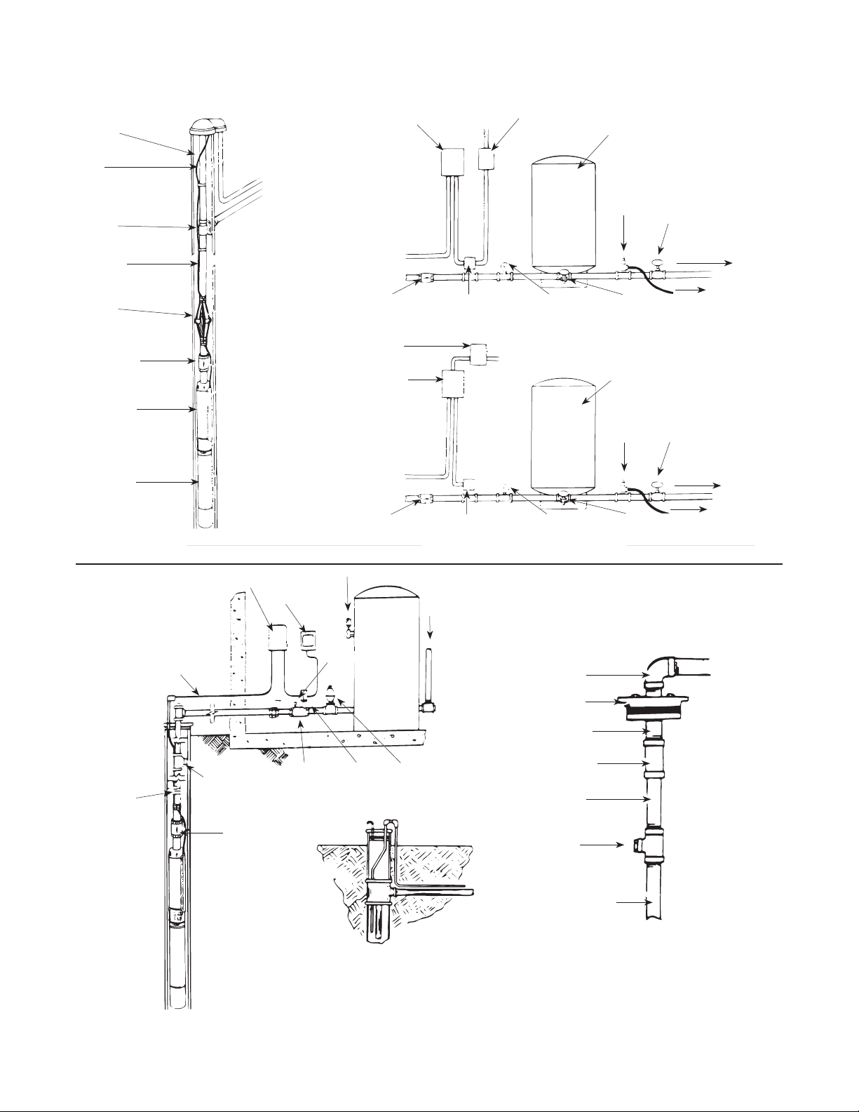
Typical Installation
Control Box
Fuse Disconnect
Box
Pre-Charged
Pressure Tank
Pressure
Relief Valve
Gate Valve
To Service
Torque
Arrestor
Fuse Disconnect
Check Valve
Submersible
Pump
Submersible
Motor
Box
Magnetic Starter
Figure 1 — Typical Installation with Pre-Charged Tank
Control Box
Submersible Power
Cable to Pump
Air Release and Pressure Gauge
Fused Switch
Box
Snifter
Check Valve
Check Valve
Tank
Pressure Switch
Pressure Switch Pressure Gauge Drain Valve
Three Phase Tank/Controls Installation
Outlet to
Service
Pressure Gauge
Single Phase Tank/Controls Installation
90º Elbow
Well Seal
Drain Valve
Pre-Charged
Pressure Tank
Pressure
Relief Valve
To Drain
Gate Valve
To Service
To Drain
Power Cable
Taped to
Pipe
Union
Bleeder Orifice
Check Valve
Check
Valve
Pressure
Switch
Relief
Valve
Figure 2 — Typical Installation with Standard Pneumatic Tank
95 North Oak Street • Kendallville, IN 46755
Pipe
Coupling
Pipe
Bleeder Valve
Rubber Orifice
Pipe
Pitless Unit
2
Page 3

CABLE SELECTION
Single Phase, 2-Wire or 3-Wire Cable, 60 Hz (Service Entrance to Motor)
Motor Rating Copper Wire Size
Volts HP 14
115
230
1 foot = .3048 meters
1/3 130 210 340 540 840 1300 1610 1960 2390 2910 3540 4210 5060
1/2 100 160 250 390 620 960 1190 1460 1780 2160 2630 3140 3770
1/3 550 880 1390 2190 3400 5250 6520 7960 9690 11770
1/2 400 650 1020 1610 2510 3880 4810 5880 7170 8720
3/4 300 480 760 1200 1870 2890 3580 4370 5330 6470 7870
1 250 400 630 990 1540 2380 2960 3610 4410 5360 6520
1-1/2 190 310 480 770 1200 1870 2320 2850 3500 4280 5240
2 150 250 390 620 970 1530 1910 2360 2930 3620 4480
3 120* 190 300 470 750 1190 1490 1850 2320 2890 3610
5 0 0 180* 280 450 710 890 1110 1390 1740 2170 2680
7-1/2 0 0 0 200* 310 490 610 750 930 1140 1410 1720
10 0 0 0 0 250 390 490 600 750 930 1160 1430 1760
15 0 0 0 0 170* 270* 340 430 530 660 820 1020 1260
Three Phase, 3-Wire, 60 Hz, 200 and 230 Volts (Service Entrance to Motor)
Motor Rating Copper Wire Size
Volts HP 14 12 10 8 6 4 3 2 1 0 00 000 0000 250 300 350 400 500
200V
60Hz 3
Phase
3 Wire
230V
60Hz 3
Phase
3 Wire
460V
Phase
3 Wire
CAUTION: Use of wire size smaller than listed will void warranty.
(*) Meet the U.S. National Electrical Code ampacity only for individual conductor 60ºC cable. Only the lengths without * meet the code for jacketed 60ºC cable. Local code
Maximum lengths shown maintain motor voltage at 95% of service entrance voltage, running at maximum nameplate amperes. If service entrance voltage will be at least motor nameplate
voltage under normal load conditions, 50% additional length is permissible for all sizes.
This table is based on copper wire. If aluminum wire is used it must be two (2) sizes larger. Example: When the table calls for #12 copper wire you would use #10 aluminum wire.
Single phase control boxes may be connected at any point of the total cable length.
Cables #14 to #0000 are AWG sizes.
1/2 710 1140 1800 2840 4420
3/4 510 810 1280 2030 3160
1 430 690 1080 1710 2670 4140 5140
1-1/2 310 500 790 1260 1960 3050 3780
2 240 390 610 970 1520 2360 2940 3610 4430 5420
3 180 290 470 740 1160 1810 2250 2760 3390 4130
5 110* 170 280 440 690 1080 1350 1660 2040 2490 3050 3670 4440 5030
7-1/2 0 0 200 310 490 770 960 1180 1450 1770 2170 2600 3150 3560
10 0 0 0 230* 370 570 720 880 1090 1330 1640 1970 2390 2720 3100 3480 3800 4420
15 0 0 0 160* 250* 390 490 600 740 910 1110 1340 1630 1850 2100 2350 2570 2980
20 0 0 0 0 190* 300* 380 460 570 700 860 1050 1270 1440 1650 1850 2020 2360
25 0 0 0 0 0 240* 300* 370* 460 570 700 840 1030 1170 1330 1500 1640 1900
30 0 0 0 0 0 0 250* 310* 380* 470 580 700 850 970 1110 1250 1360 1590
1/2 930 1490 2350 3700 5760 8910
3/4 670 1080 1700 2580 4190 6490 8060 9860
1 560 910 1430 2260 3520 5460 6780 8290
1-1/2 420 670 1060 1670 2610 4050 5030 6160 7530 9170
2 320 510 810 1280 2010 3130 3890 4770 5860 7170 8780
3 240 390 620 990 1540 2400 2980 3660 4480 5470 6690 8020 9680
5 140* 230 370 590 920 1430 1790 2190 2690 3290 4030 4850 5870 6650 7560 8460 9220
7-1/2 0 160* 260 420 650 1020 1270 1560 1920 2340 2870 3440 4160 4710 5340 5970 6500 7510
10 0 0 190* 310 490 760 950 1170 1440 1760 2160 2610 3160 3590 4100 4600 5020 5840
15 0 0 0 210* 330 520 650 800 980 1200 1470 1780 2150 2440 2780 3110 3400 3940
20 0 0 0 0 250* 400 500 610 760 930 1140 1380 1680 1910 2180 2450 2680 3120
25 0 0 0 0 0 320* 400 500 610 750 920 1120 1360 1540 1760 1980 2160 2520
30 0 0 0 0 0 260* 330* 410* 510 620 760 930 1130 1280 1470 1650 1800 2110
1/2 3770 6020 9460
3/4 2730 4350 6850
1 2300 3670 5770 9070
1-1/2 1700 2710 4270 6730
2 1300 2070 3270 5150 8050
3 1000 1600 2520 3970 6200
5 590 950 1500 2360 3700 5750
7-1/2 420 680 1070 1690 2640 4100 5100 6260 7680
60
Hz 3
10 310 500 790 1250 1960 3050 3800 4680 5750 7050
15 0 340* 540 850 1340 2090 2600 3200 3930 4810 5900 7110
20 0 0 410* 650 1030 1610 2000 2470 3040 3730 4580 5530
25 0 0 0 530* 830 1300 1620 1990 2450 3010 3700 4470 5430
30 0 0 0 430* 680 1070 1330 1640 2030 2490 3060 3700 4500 5130 5860
40 0 0 0 0 500* 790 980 1210 1490 1830 2250 2710 3290 3730 4250
50 0 0 0 0 0 640* 800 980 1210 1480 1810 2190 2650 3010 3420 3830 4180 4850
60 0 0 0 0 0 540* 670* 830* 1020 1250 1540 1850 2240 2540 2890 3240 3540 4100
75 0 0 0 0 0 0 0 680* 840* 1030 1260 1520 1850 2100 2400 2700 2950 3440
100 0 0 0 0 0 0 0 0 620* 760* 940* 1130 1380 1560 1790 2010 2190 2550
requirements may vary.
12 10 8 6 4 3 2 1 0 00 000 0000
95 North Oak Street • Kendallville, IN 46755
3
Page 4
IL0094
READ THESE INSTRUCTIONS COMPLETELY BEFORE INSTALLATION
ASSEMBLY
CAUTION: Be sure pump size corresponds with
horsepower size of motor. If pump size exceeds
recommended motor, overloading of motor and
damage to the motor could result.
1. If not yet assembled, check that the pump and
motor mounting faces are free from dirt.
2. Assemble the pump liquid end and motor
together so that mounting faces are in contact.
Then tighten assembly bolts evenly.
NOTE: Apply non-toxic FDA approved waterproof
grease such as Mobile 102, Texaco CYGNUS2661 or
equivalent to the coupling before assembly of pump
coupling to motor shaft. This will prolong spline life
and prevent abrasives from entering the spline area.
3. Check for free rotation of the pump and motor. A
slight drag is permissible.
4. Assemble the pump lead guard over the motor
leads.
CAUTION: Do not cut or pinch lead wire during
assembly.
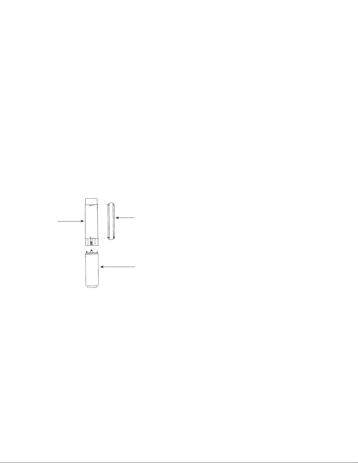
5. Assemble suction screen to pump mounting ring.
Lead Wire
Liquid End
Figure 3
Guard
Motor
PRE-INSTALLATION
To save possible added expense and extra trips,
observe and complete as many as possible of the
following precautions and pre-installation procedures
before going to the job site or beginning the
installation.
IMPORTANT PRECAUTIONS
1. Prior to installation, inspect the pump for damage.
Check for free pump and motor rotation. A slight
drag is permissible.
2. Check to make certain that the voltage of the
motor end and control agree with the available
phase and voltage. Check power source. Check
electrical supply for correct fusing, correct wire
size, and adequate grounding and transformer
size.
WARNING: Since most submersible pump problems
are electrical, it is very important that all electrical
work be done properly. Therefore, all electrical hook-
up work or electrical service work should be done by a
qualified electrician or service man only!
3. Throughout installation, take care not to damage
the insulation of the electrical cable or motor
leads. Never support the weight of the unit by
electrical cable or motor leads.
4. Before the pump is installed, the well should be
pumped free of sand and other foreign matter
with a test pump. The warranty is void if it is
used to clean the well.
5. Follow wiring directions in the control box and
make momentary tests to see that motor runs.
(It is normal to hear some noise from the pump
when you are momentarily testing it). Do not run
pump dry for more than three (3) seconds.
MAJOR WELL COMPONENTS (see Figures 1 & 2)
1. Submersible Pump — A submersible pump is a
multi-stage centrifugal. Each stage consists of an
impeller and diffuser. Water pressure increases in
equal amounts as it passes from stage to stage.
The more stages, the higher the pressure the
pump will develop.
2. Submersible Motor — Submersible pumps can
be powered by either single phase or three phase
motors. Make certain that the motor corresponds
with the horsepower required by the pump.
Failure to do so, could result in overloading of the
motor and motor damage.
3. Control Box — Single phase submersible motors
require the use of an above ground control box
for starting. Operation of these motors without
control boxes or with incorrect boxes can result in
failure of motors which will void the warranty.
4. Magnetic Starters and Overload Protection
— Three phase submersible motors require the
use of an above ground magnetic starter and
overload protection. Operation of these motors
without or incorrect starters and protectors will
result in the failure of motor which will void
the warranty. See Magnetic Starter Chart for
the correct selection of magnetic starters and
ambient compensated quick trip protectors.
5. The Well — The well should be sand free and
have a sufficient flow of water to supply the
pump. Clear well of sand and any other foreign
matter with a test pump before installing the new
submersible pump.
CAUTION: Using the submersible pump to clean the
well will void the warranty.
6. When drilling a new well in an area where sand is
a problem, a sand screen should be installed to
protect the pump and motor.
7. The well should be straight so damage during
installation does not occur to the pump or motor
by becoming lodged in a crooked well casing.
95 North Oak Street • Kendallville, IN 46755
4
Page 5
8. The complete pump and motor should be
IL0077
IL0096
submerged at least ten feet below the draw
down level of the well, and the motor should be
a minimum of ten feet off the bottom of the well
(Figure 4).
9. The Piping — Install the pump with pipe of the
same diameter as the discharge port of the pump
or larger.
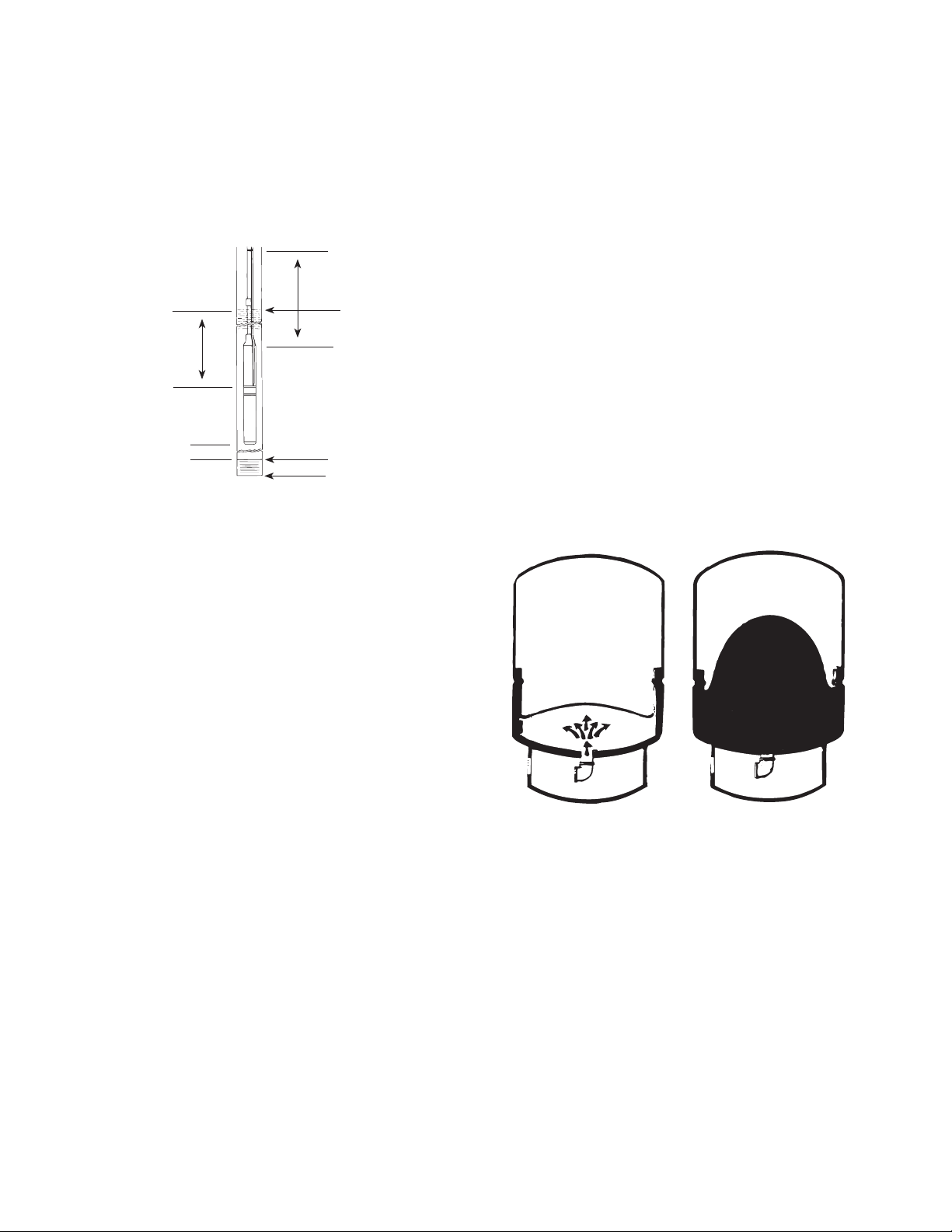
10 ft.
Drawn Down Water
Level
10 ft.
10 ft. Min.
Figure 4
Top of Well Screen
Bottom of Well
NOTE: Use of pipe smaller that the discharge port
of the pump will restrict the capacity of the pump and
lower its operating performance.
10. Check Valve — A check valve is required on all
submersible installations. This valve maintains
water within the pipe when the pump is running. A
line check should be installed within 25 feet of the
pump and below the draw down level of the water
supply.
a. For well depths exceeding 200 feet, it is
suggested that an additional check valve be
installed every 125 feet.
b. An additional check valve should be installed in
the horizontal line between the well top and the
pressure tank (See Figures 1 & 2).
CAUTION: Make certain that the check valve is
pointing in the right direction, arrow pointing towards
the tank.
11. Torque Arrester — To center the pump as it is
being lowered into the well, a torque arrester is
recommended. This will also minimize the pump
whipping due to the starting torque of the motor
(See Figure 2).
NOTE: On plastic pipe installations a torque
arrester must be installed. Cable guards should also
be installed.
12. Pressure Tank — The purpose of the pressure
tank is to allow an amount of water to be drawn
before the pressure drops enough to cause the
pump to start. Without a pressure tank, the pump
would start and stop continuously when water is
drawn. There are two types of pressure tanks,
the standard tank that requires an air volume
control and the pre-charged tank.
a. On a standard pneumatic tank system, air
is introduced to compensate for that which
is absorbed by the water. Each time the
pump cycles air is added to the tank through
a bleeder and snifter valve. The excess air
is released by a float assembly (air volume
control) in the upper side tapping of the tank
(See Figure 2).
b. In a pre-charged tank, a flexible diaphragm
or bladder separates the air and water areas
of the tank. The air chamber is pre-charged
by means of a tire valve with pressure 2 PSI
less than the cut-on pressure of the pump.
Because the air is not in contact with the
water, it cannot be absorbed by the water.
Therefore, the original charge of air is never
lost.
13. In pre-charged tank systems, none of the
fittings for air introduction or air level control are
required (Figure 1). The piping in the well is also
different for the two systems. The pre-charged
tank system does not require a bleeder orifice
assembly, which simplifies the installation.
Pump On. Water Enters
The Reservoir
Figure 5
System Filled.
Pump Off
14. The tank size should be selected to keep
the pump starts per day as low as practical
for maximum life. Excessive motor cycling
accelerates motor bearing and spline wear, pump
wear and contact erosion. Use as a guide, 100
starts per day (24 hours) on single phase motors
and 300 starts per day on three phase units.
15. Pressure Switch — The pressure switch provides
for automatic operation. The pump starts when
the pressure drops to the switch cut-in setting
and stops when the pressure reaches the switch
cut-out setting. The pressure switch must be
installed as close to the tank as possible (Figures
1 & 2).
16. Pressure Relief Valve — A properly sized
pressure relief valve must be installed on any
95 North Oak Street • Kendallville, IN 46755
5
Page 6
installation where the pump pressure can exceed
IL0097
the pressure tank’s maximum working pressure
or on systems where the discharge line can be
shut off or obstructed. The relief valve drain port
should be piped to a drain (Figures 1 & 2).
WARNING: Not providing a relief valve can cause
extreme over pressure, which could result in personal
and/or property damage.
17. Pitless Adapter — A pitless adapter provides
below grade discharge while maintaining above
grade access to the well. Placed below the frost
line they are frost proof and also prevent well
contamination by providing a water tight seal
between the vertical drop pipe and the horizontal
service pipe connection (Figure 1).
18. Well Seal — On well seal installations the
piping in the well projects above the well and is
connected above ground to the system piping by
means of a tee or elbow. Since the plumbing is
above ground, it must be protected from freezing
(Figure 2).
19. Submersible Cable — Submersible power cable
must be UL listed for submersible pump application.
Selecting the proper cable size is important.
Undersized cable results in a too low voltage supply
to the pump motor and ultimate motor failure.
Oversized cable is costly and not necessary. Refer
to cable selection chart for proper cable selection.
Cable is selected for the maximum pump setting
plus the offset distance to the service entrance.
20. Ground Wire — The National Electric Code (NEC
250-43) requires a separate ground wire be run
down the well to the submersible pump and to be
connected to all exposed metal parts of the pump
and motor. Refer to the most recent National
Electric Code (NEC) for additional grounding
information. All wiring should be done by a
competent electrician.
INSTALLATION
SUBMERSIBLE CABLE INSTALLATION
1. Check power source. Check electrical supply for
correct fusing, correct wire size, and adequate
grounding and transformer size.
WARNING: Since most submersible pump problems
are electrical, it is very important that all electrical
work be done properly. Therefore, all electrical hookup work or electrical service work should be done ny a
qualified electrician or serviceman only!
2. Follow wiring directions in the control box and
make momentary tests to see that the motor
runs. Do not run pump dry for more than
three (3) seconds. If test is satisfactory, proceed
to Step 3 (cable splice).
3. First check cable size against the Submersible
Wire Size Chart. Use extreme care; this is a very
important step. If required length falls between
two wire sizes, use the larger of the two wire
sizes (smaller number).
IMPORTANT: Use of wire sizes smaller than those
specified in the charts will cause low starting voltage,
may cause early pump failure and will void the
warranty. Larger wire sizes may always be used for
better operating economy.
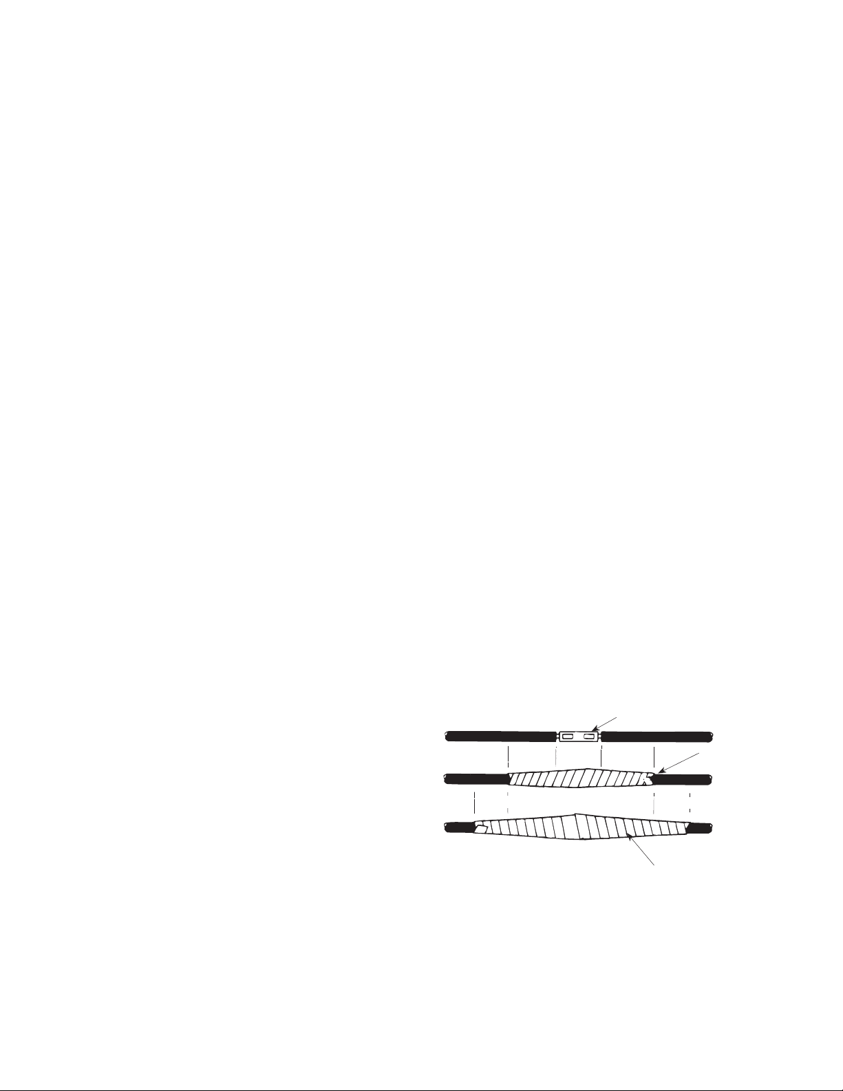
4. Splice motor leads to submersible cable with
commercially available potting, heat shrink
splicing kits or by careful tape splicing. Tape
splicing should use the following procedure.
a) Strip individual conductor of insulation only as
far as necessary to provide room for a stake
type connector. Tubular connectors of the
staked type are preferred. If connector O.D. is
not as large as cable insulation, build-up with
rubber electrical tape.
b) Tape individual joints with rubber electrical
tape, using two layers; the first extending two
inches beyond each end of the conductor
insulation end, the second layer two inches
beyond the ends of the first layer. Wrap
tightly, eliminating air spaces as much as
possible.
c) Tape over the rubber electrical tape with #33
Scotch electrical tape, (Minnesota Mining Co.)
or equivalent, using two layers as in step “B”
and making each layer overlap the end of the
preceding layer at least two inches.
5. In the case of a cable with three conductors
encased in a single outer sheath, tape individual
conductors as described, staggering joints.
Total thickness of tape should be less than the
thickness of the conductor insulation.
GROUND WIRE INSTALLATION
WARNING: Motor frame must be connected to power
supply ground or fatal electrical shock may result.
Staked Connector
Rubber Tape
2”
Figure 6
2”
2”
2”
PVC Electrical Tape
NOTE: All electrical wiring should be done by a
competent electrician.
1. Grounding the submersible pump is
accomplished by running a copper grounding
wire from the pump motor to the main electrical
system ground.
95 North Oak Street • Kendallville, IN 46755
6
Page 7

2. The ground wire to be used must be of the same
IL0098
IL0099
size as the submersible power cable. It may be
insulated or bare. If insulated, it must be green,
with or without yellow stripe(s). The ground wire
may be part of, or separate from, the supply
cable. It may be continuous or spliced above the
pump along with the supply cable.
3. The motor lead wire assembly includes a green
insulated ground lead. Splice the ground wire to
the green insulated lead as shown in Figure 6.
4. The other end of the ground wire will be
connected to the power supply grounding
terminal or to the control panel ground bar if it is
connected to the power supply ground.
NOTE: See section entitled Grounding for detailed
grounding instructions.
INSULATION AND CONTINUITY TEST
1. It is recommended that this test be done when
the splicing is complete and pump is being test
run in a tank of water. This test can be repeated
after installation in well but before the final
electrical hook-up is made to the control box or
pressure switch (see Figures 7 & 8).
2. Zero the ohmmeter by clipping the leads together
and adjusting the zero ohm knob until the needle
indicates zero. Zero the ohmmeter before each
use or every time selector switch is changed.
3. Clip one ohmmeter lead to bare cable end.
4. Clip the other lead to edge of steel tank in which
pump and cable are submerged. If pump is
already in the well, clip lead to discharge pipe
metal well casing or bare ground wire.
5. A reading of less that 1,000,000 ohms indicates
that cable or splice is grounded. Slowly raise
cable from the water at the ohmmeter end.
When trouble spot moves clear of the water,
needle will move toward infinity reading. In
an old installation with the pump in the well,
a reading of 20,000 ohms or less indicates a
breakdown in the insulation; in this case pull the
pump.
PUMP INSTALLATION
Figure 7
Figure 8
1. The following pump installation instructions use
Schedule 80 PVC pipe or galvanized pipe. If
either of these two types are used, a foot clamp
or vise will be required to hold the PVC or
galvanized pipe when connecting the next pipe
length.
2. Install the pump in a well which is sand-free,
straight, and has sufficient flow of water to supply
the pump. Clear well of sand and any other
foreign matter with a test pump before installing
the submersible pump.
NOTE: Using the submersible pump to clean the
well will void the warranty. When drilling a new well
in an area where sand is a problem, a sand screen
must be installed to protect the pump and motor.
3. Chlorinate the well first. Drop 24 to 48 HTH
(chlorine) tablets into the well before lowering
the pump into the well. This will prevent
contamination and the growth of iron bacteria
which could later plug the well and the pump.
The chlorinated water will be pumped out of the
system when testing the pump flow.
4. BE SURE the top edge of the well casing is
perfectly smooth; sharp or jagged edges can cut
or scrape the cable and cause a short.
5. Install a line check valve within 25 feet of the
pump and below the draw down level of the water
supply. The check valve should be the same size
as the discharge outlet of the pump or larger.
NOTE: Use of pipe smaller that the discharge
tapping of the pump will restrict the capacity of the
pump and lower its operating performance.
6. When connecting the first length of pipe and
placing the pump in the well casing, care should
be maintained to center the pump in the well. It
is easier to handle the pump if a short piece of
95 North Oak Street • Kendallville, IN 46755
7
Page 8

pipe is installed first, rather than a long piece.
Install the check valve at the end of the first
piece of pipe prior to lowering the pump into the
well. Maintain alignment as the pump is placed
and lowered into the well, a torque arrester is
recommended. Position the torque arrestor
to within 6” of the pump discharge and clamp
arrestor to pipe. Wrap the pipe with enough tape
at top and bottom of torque arrestor to keep it
from sliding up the pipe while the pump is being
lowered into the well.
7. If not already done, splice the electrical cable
to the motor leads. The cable and ground wire
should be taped to the discharge pipe. Tape the
cable about 5 feet above the discharge and every
20 feet thereafter. Install cable guards if required
to eliminate rubbing against the well casing. Do
not let the cable drag over the edge of the well
casing. Never allow the weight of the pump to
hang on the cable alone.
8. Lower the pump into the well slowly without
forcing. Use a vise or foot clamp to hold the pipe
while connecting the next length. A boom, tripod
or pump setting rig is recommended. Lower
pump to approximately 10 feet below maximum
draw down of the water if possible and keep
approximately 10 feet from the bottom. DO NOT
set pump on bottom of well. Before each new
length of pipe is added, attach the coupling to the
top of the pipe length. This will provide a stop for
the foot clamp to hold while the next section of
pipe is being installed.
9. On a standard tank with an air volume control
a bleeder orifice is required. Install the bleeder
orifice in the discharge pipe 5 feet or more below
the snifter valve. See Figure 2 and the table
below.
WELL SEAL/PITLESS ADAPTER INSTALLATION
Distance Table
Tank Size
Gallons
42
82
120
220
315
525
Depth From Horizontal Check
Valve To Bleeder Orifice
5
10
15
15
20
20-35
Installations that use a pre-charged pressure tank
do not require a bleeder orifice.
1. All installations should have a well seal. Make
sure the seal is seated and tighten the bolts
evenly.
NOTE: Be sure to assemble the tee to the pipe
above the well seal to prevent dropping the pipe and
pump down the well as you lower it.
IMPORTANT: Well seal and piping must be
protected from freezing.
2. On a pitless adapter installation, the connection to
the system supply line is made below ground. Install
the pitless adapter following the instructions included
with particular brand or design being used in the
installation.
NOTE: Follow ALL applicable state and local
plumbing codes.
PRELIMINARY TEST RUN
1. When pump is at desired depth, install throttle
valve for preliminary test run. Wire single
phase motors through the control box, following
instructions in box regarding color coding of
wires, etc. Wire 3-phase motors through a
magnetic starter. Test cable for continuity with an
ohmmeter.
2. With pump discharge throttled, run pump until
water is clear of sand or any other impurities.
Gradually open discharge.
CAUTION: Be sure you do not stop pump before water
runs clear. This may take several hours. If pump
stops with sand in it, it will lock.
3. If pump lowers water in the well far enough
to lose prime, either lower pump in the well (if
possible) or throttle discharge to capacity of the
well.
4. If well is low capacity, use a low water level
control.
5. On 3-phase units, establish correct motor rotation
by running in both directions. Change rotation by
exchanging any two of the three motor leads. The
rotation that gives the most water flow is always
the correct rotation.
PRESSURE TANK INSTALLATION
1. On a new installation, install the pressure tank
along with the pressure switch, pressure gauge,
pressure relief valve, check valve, gate valves
and unions as shown in Figures 1 & 2.
2. On replacement pump installations be sure that
the tank system is in good operating condition, as
a water logged tank may cause pump failure.
ELECTRICAL HOOK-UP
WARNING: Since most submersible pump problems
are electrical, it is very important that all electrical
work be done properly. Therefore, all electrical hookup work or electrical service work should be done by a
qualified electrician or serviceman only!
WARNING: Always disconnect power source before
working on or near motor, its connected load or
control box and wiring. If the power disconnect is out
of sight, lock it in the open position and tag to prevent
unexpected application of power.
95 North Oak Street • Kendallville, IN 46755
8
Page 9

1. Proceed with electrical hook-up matching cable
IL0100
IL0101
IL0102
colors and following the wiring diagrams (Figures
9, 10 &11) or inside the lid of the control box.
WARNING: Connect motor leads momentarily for
correct rotation before installing pump in well.
FUSE SIZES
Fused Disconnect
Switch
Control Box
L1
L2
Lightening
Arrestor
Figure 9 — Single Phase Control Box
Lightening
Arrestor
Figure 10 —
Single Phase Control Box with Contactor
Pressure
Switch
Ground
Control Box
L1
SW
3
2
T1
Y
R
Red
To Motor
L2
R
Ground
To Motor
L1
1
V M
T1
Yellow
Red
T2
Motor
B
Black
Ground
Fused Disconnect
Switch
B
Y
Black
L3
X2
T3
Ground
T3
Ground
Pressure Switch
Fused Disconnect
Switch
Lightening
Yellow
L2
W
T2
Pressure Switch
Ground
Ground
Arrestors
1. For proper sizing of fuses for fuse disconnect
box, see Motor Data Charts. Improperly sized
fuses will result in fuses blown or circuit breakers
tripped.
GROUNDING
Proper Grounding of Submersible Motors
1. The purpose of grounding any electrical
apparatus is to prevent an electrical shock hazard
if exposed metal becomes connected to an
electrical circuit. This can occur from a defect in
construction of the electrical equipment, physical
damage, or a breakdown in the insulation of the
equipment. Grounding prevents shock hazard by
keeping exposed metal from reaching a voltage
level which could endanger anyone coming in
contact with the electrical equipment. Fault
current is “drained” by the ground conductor, and
if the fault is severe enough, the circuit will be
opened by the fuse or circuit breaker.
2. The U.S. National Electrical Code (NEC) requires
that motor-operated water pumps, including
submersible type regardless of voltage, shall
be grounded. The Canadian Electrical Code
specifically discusses grounding requirements
for submersible pumps. Interpretation of these
and other codes may vary in different states and
localities, but all applicable national, state, and
local codes should always be followed.
3. Any submersible motor which is to be run tested
out of the well should be grounded to prevent
possible shock hazard during the test.
NOTE: Always disconnect all power when making
ohmmeter check and while pulling or installing a
pump.
4. The most logical way to “frame” ground a
submersible motor is normally as follows:
a. Run an extra wire with the motor power
conductors. This wire must be sized to meet
Table 250-95 in the U.S. National Electrical
Code. If code information is unavailable, using
the same size wire as the power conductors is
normally adequate.
b. The ground wire may be insulated or bare.
If insulated, it must be green with or without
yellow stripe(s). The ground wire may be
part of, or separate from the supply cable. It
may be continuous or spliced above the pump
along with the supply cable.
c. Connect the green or bare ground wire to the
green ground wire of the submersible motor
lead assembly. If the lead wire assembly does
not include a separate ground wire, attach a
lug to the ground wire and place the lug over
one of the motor studs above the pump intake
flange so the pump will not be cocked. The
Figure 11 — Three Phase Magnetic Starter
95 North Oak Street • Kendallville, IN 46755
9
Page 10

ground lug will then be secured with the nut
IL0103
which holds the pump on the motor.
d. Connect the other end of the ground wire to
the power supply grounding terminal or to the
control panel ground bar if it is connected to
the power supply ground.
e. All connections should be tight and corrosion
resistant, including screws, lugs or clamps.
Grounding Control Boxes
1. It is recommended the control box grounding
terminal always be connected to circuits which
include a grounding conductor. In fact, this is a
requirement of the National Electrical Code. If
the circuit has no grounding conductor and no
metal conduit from the box to supply panel, use
a wire at least as large as line conductors and
connect from supply panel to the control box and
to the motor lead ground wire.
WARNING: Failure to ground the box frame can
result in a fatal electrical shock hazard if a circuit fault
occurs.
WARNING: Serious or fatal electrical shock may result
from failure to connect all metal plumbing, and the
motor if outside a drilled well, to the power supply
grounding terminal with wire no smaller than motor
cable wires. Do not use motor in swimming area.
Grounding Lightning Arrestors In Control Boxes
1. When the box has a lightning arrestor, it must be
grounded, metal to metal, all the way to the water
strata for the lightning arrestor to be effective.
Grounding the arrestor to a driven ground rod
provides little or no protection for the motor.
SUBMERSIBLE MOTOR COOLING
1. When the pump is set below any screen
openings or below the bottom of the casing a top
feeding well condition can exist which reduces
the rate of cooling water flow past the motor.
2. If the flow rate is less than specified a flow
indicator sleeve or an alternate method of
increasing water velocity past the motor must be
used for proper cooling.
Minimum Velocity Past the Motor
4” dia. motor – .25 ft./sec. (7.62 cm/sec)
6” dia. motor – .5 ft./sec/ (15.24 cm/sec)
3. A flow inducer sleeve is a tube over the motor,
closed off above the pump intake and extended
to the bottom of the motor or lower. The sleeve
material is corrosion resistant metal or heavy
plastic (See Figure 12).
4. A flow inducer sleeve should always be used
when the pump is in an open body of water.
Make sure that such an installation is grounded.
MAINTENANCE
Pump Body
Stainless Steel
Worm Gear Clamps
Screen, Intake
Flow Inducer Sleeve
(Corrosion Resistant Material)
Submersible Motor
Centering Bolt
Corrosion Resistant
(3 Places)
All Water Flows Past
Motor
Figure 12
Required Cooling Flow
Minimum GPM required for motor cooling in water
up to 86ºF (30ºC).
Inches
Casing or
Sleeve I.D.
4
5
6
7
8
10
12
14
16
4” High
Thrust Motor
.25 ft/sec
GPM
1.2
7
13
20
30
50
80
110
150
6” Motor
.5 ft/sec
GPM
—
—
9
25
45
90
140
200
280
8” Motor
.5 ft/sec
GPM
—
—
—
—
10
55
110
170
245
SERVING SUBMERSIBLE MOTOR AND
CONTROLS
1. The following is included to assist in motor
installation and servicing. These procedures are
limited to the motor and control system: they do
not include pump requirements.
TIGHTENING LEAD CONNECTOR JAM NUT
1. It is recommended that ssible damage from
removal may prevent resealing. Torque the jam
nut from 15 to 20 lb. ft. on Franklin 4” motor and
60 to 70 lb. ft. on a 6” motor.
CABLE IDENTIFICATION WHEN COLOR CODE IS
LOST
(Single Phase Only)
If the colors on the individual drop cables cannot
be determined and the leads cannot be positively
identified, proceed as follows:
95 North Oak Street • Kendallville, IN 46755
10
Page 11

1. Disconnect all three drop cables from the control
IL0104
box. For temporary identification, tie a numbered
tag to each cable (1, 2, 3).
2. Using an ohmmeter, check the resistance
between cables as follows:
Unknown Value Known Value
Cable 1 to Cable 2
Cable 1 to Cable 3
Cable 2 to Cable 3
Lowest - Black to Yellow
Intermed. - Red to Yellow
Highest - Black to Red
NOTE: The “yellow” cable is that giving lowest and
intermediate readings and the “red” cables gives
highest and intermediate readings.
Example:
• 1 to 2 gives 7 ohms (highest reading)
• 1 to 3 gives 5 ohms (intermediate reading)
• 2 to 3 gives 2 ohms (lowest reading)
• Cable 3 gave both intermediate and lowest
reading
• Cable 3 is the yellow cable
• Cable 1 gave both highest and intermediate
readings
• Cable 1 is the red cable
• Cable 2 is the black cable
The actual ohm values are not important. The
method works regardless of the actual ohm readings;
what matters is which reading is highest, which
intermediate, and which lowest.
THREE PHASE POWER UNBALANCE
1. A full three phase supply is recommended for all
three phase motors, consisting of three individual
transformers or one three phase transformer.
So-called “open” delta or wye connections using
only two transformers can be used, but are more
likely to cause problems from current unbalance.
Transformer Capacity Required for
Submersible Motors
Smallest KVA Rating — Each
Open WYE or
2 Transformers
DE LTA
2
2
3
5
7.5
10
15
15
20
25
30
35
40
50
65
Transformer
Closed WYE or
DELTA
3 Transformers
1.5
7.5
10
10
15
20
20
25
30
40
1
2
3
5
5
Motor
HP
1-1/2
2
3
5
7-1/2
10
15
20
25
30
40
50
60
75
100
Total
Effective
KVA
Required
3
4
5
7.5
10
15
20
25
30
40
50
60
75
90
120
2. Transformer ratings should be no smaller than
listed in the table for supply power to the motor
alone. Open Wye or Delta systems often
suffer from line unbalance, which can cause
poor motor performance, nuisance overload
tripping, or premature motor failure. For the
best performance current unbalance should not
exceed 5 percent. If the unbalance cannot be
corrected by rolling leads, contact the power
company.
INSULATION RESISTANCE
Unbalance Formula
Percent
Current = Max difference from average x 100
Unbalance average
Example:
Currents are 80, 79, 84 amps (Lines 1-2 & 3)
Avg. Currents = 80 + 79 + 84 = 81
3
Percent
Current
Unbalance
Full Three Phase
Figure 13
84 - 81 x 100 = 3.7%
81
Open Delta
Insulation resistance tests indicate the value of the
motor, cable, and splice insulation system by
measuring resistance in ohms between motor leads
and ground. Low readings indicate a breakdown
somewhere in the insulation system.
1. Set ohmmeter to RX100K or highest scale. (For
best results use a megohmmeter).
2. Short meter leads together and adjust indicator to
zero.
3. Be sure power is turned off!
4. Connect one meter lead to a motor lead and the
other meter lead to ground.
a. If motor is out of water, measure from lead to
motor frame.
b. If motor is installed in water, ground reference
should be metal well casing (if submerged),
95 North Oak Street • Kendallville, IN 46755
11
Page 12

metal drop pipe, or an extra wire extending
into the ground water.
5. Readings and Conditions, motor installed in well:
a. 2,000,000 ohms or more - insulation
completely acceptable.
b. 500,000 to 2,000,000 ohms - insulation
in reasonably good condition. Acceptable.
Should be considered marginal for new motor.
c. 20,000 to 500,000 ohms - insulation seriously
damaged, but motor may still operate.
d. Less than 20,000 ohms - severe insulation
damage. Motor probably not operable.
WINDING RESISTANCE
Winding resistance tests indicate whether or
not windings are internally correct, shorted, or
open. Winding resistance should be considered
independently of insulation resistance readings.
1. Set ohmmeter to RX1. Short meter leads
together and adjust indicator to zero.
2. Be sure power is turned off.
3. Connect ohmmeter between two motor leads.
a. Three wire single phase: Yellow-Black
indicates main winding resistance; Yellow-Red
indicates start winding resistance.
b. Three phase: Resistance values should be
equal on all three phases: Yellow-Black;
Yellow-Red; Black-Red.
4. Correct readings should be equal to the Line-toLine resistance values from the specifications
section for a given motor, plus the resistance of the
drop cable from the table below.
5. Conditions:
Resistance (Ohms) Per 100 Feet of Copper Cable
(Round Trip)
AWG 14 12 10 8 6 4 2 0
Ohms .5 .3 .2 .12 .08 .05 .03 .02
a. If one ohm value is less than specified, that
winding is shorted.
b. If one ohm value is greater than specified, that
winding is open, or there is a poor connection
in that circuit.
c. On 3-wire single phase, if one ohm value is
greater than specified and one ohm value is
less than specified, the leads are mixed. See
the section entitled “Cable Identification When
Color Code Is Lost.”
TESTING LOAD CURRENT AMPS
To test load current amps a clamp-on ammeter is
required. Since the ammeter measures current flow,
the motor must be running.
1. Pull the motor lead wire, being measured, (red,
yellow or black) away from all other wires.
2. Set ammeter to the highest scale. (If starting
a motor leave on the scale until current settles
down).
3. Place tongs of meter around wire.
4. Change meter scale to one that gives the best
accuracy. This will be a reading between mid
scale and full scale.
5. Compare reading with current load amps on
motors data chart.
6. Test each motor lead.
ONE YEAR LIMITED WARRANTY
This product is warranted for one year from the date of
purchase or two years from the date of manufacture, whichever
occurs first. Subject to the conditions hereinafter set forth, the
manufacturer will repair or replace to the original consumer, any
portion of the product which proves defective due to defective
materials or workmanship. To obtain warranty service, contact the
dealer from whom the product was purchased. The manufacturer
retains the sole right and option to determine whether to repair
or replace defective equipment, parts or components. Damage
due to conditions beyond the control of the manufacturer is not
covered by this warranty.
THIS WARRANTY WILL NOT APPLY: (a) To defects or malfunctions
resulting from failure to properly install, operate or maintain
the unit in accordance with printed instructions provided; (b)
to failures resulting from abuse, accident or negligence; (c) to
normal maintenance services and the parts used in connection
with such service; (d) to units which are not installed in
accordance with normal applicable local codes, ordinances and
good trade practices; and (e) the unit is used for purposes other
than for what it was designed and manufactured.
RETURN OF WARRANTED COMPONENTS: Any item to be
repaired or replaced under this warranty must be returned to the
manufacturer at Kendallville, Indiana or such other place as the
manufacturer may designate, freight prepaid.
THE WARRANTY PROVIDED HEREIN IS IN LIEU OF ALL OTHER
EXPRESS WARRANTIES, AND MAY NOT BE EXTENDED OR
MODIFIED BY ANYONE. ANY IMPLIED WARRANTIES SHALL
BE LIMITED TO THE PERIOD OF THE LIMITED WARRANTY
AND THEREAFTER ALL SUCH IMPLIED WARRANTIES ARE
DISCLAIMED AND EXCLUDED. THE MANUFACTURER
SHALL NOT, UNDER ANY CIRCUMSTANCES, BE LIABLE FOR
INCIDENTAL, CONSEQUENTIAL OR SPECIAL DAMAGES,
SUCH AS, BUT NOT LIMITED TO DAMAGE TO, OR LOSS
OF, OTHER PROPERTY OR EQUIPMENT, LOSS OF PROFITS,
INCONVENIENCE , OR OTHER INCIDENTAL OR CONSEQUENTIAL
DAMAGES OF ANY TYPE OR NATURE. THE LIABILITY OF THE
MANUFACTURER SHALL NOT EXCEED THE PRICE OF THE
PRODUCT UPON WHICH SUCH LIABILITY IS BASED.
This warranty gives you specific legal rights, and you may have
other rights which vary from state to state. Some states do not
allow limitations on duration of implied warranties or exclusion
of incidental or consequential damages, so the above limitations
may not apply to you.
FOR YOUR WARRANTY PROTECTION, THE WARRANTY
REGISTRATION MUST BE COMPLETED AND RETURNED TO
THE WARRANTY INFORMATION CENTER WITHIN TEN DAYS OF
INSTALLATION. WARRANTY VALID IN CANADA AND MEXICO.
95 North Oak Street • Kendallville, IN 46755
12
Page 13

Single Phase Control Box Checking and Repairing Procedures
CAUTION: Turn power off and discharge capacitors before using ohmmeter.
TEST PROCEDURE
General Procedures 1. Disconnect line
2. Inspect for damaged or burned parts, loose connections, etc.
3. Check for misconnections against diagram in control box
4. If problem has not been found, check motor per Motor Data Chart and
control box as indicated below
Use of Ohmmeter 1. Ohmmeter such as Simpson Model #372 or #260, Triplett Model #630 or
#666 may be used
2. Whenever scales are changed, short ohmmeter leads and “zero balance”
meter
Ground (Insulation Resistance) Test 1. Ohmmeter Setting: Highest scale (usually R x 100K or 4 x 10,000)
2. Terminal Connections: One ohmmeter lead to “Ground” terminal on control
box and touch other lead to each of the other terminals on terminal board
3. Ohmmeter Reading: Pointer should remain at (∞) and not deflect
Overload Protector 1. Ohmmeter Setting: R x 1
2. Terminal Connections: Connect one ohmmeter lead to Terminal Black and
other lead to:
a. Terminal L
b. Terminal L
3. Ohmmeter Reading: Should be 0 to 0.5 ohms maximum
Capacitor Tests 1. Ohmmeter Setting: R x 1,000
2. Terminal Connections: One ohmmeter lead to relay terminal #1 and other to
black terminal on terminal board
3. Ohmmeter Reading: Pointer should swing toward “zero” and “float” back
to (∞). Capacitor is shorted if pointer does not move back to (∞), open if it
does not move from (∞)
4. If reading is not as above, disconnect capacitor from overload and test each
component
Relay Coil Test
(potential relays only)
1. Ohmmeter Setting: 4 x 1,000 (or R x 100)
2. Terminal Connections: #6 and #2 on Relay
3. Ohmmeter Reading:
Relay Contact Test
(potential relays only)
Most of the cases of inoperative relay contacts can be detected as follows:
1. Ohmmeter Setting: 4 x 1.
2. Terminal Connections: Terminal #1 and Terminal #2 on Relay.
3. Ohmmeter Reading: Should be “zero”.
NOTE: This test verifies “making” of contacts. If it is desired to test
“Opening” and closing of contacts:
a. Connect control box components in control box as indicated on diagram in
control box cover.
b. Connect three leads from motor of correct rating to control box terminal
board.
c. Connect power source voltage to L
d. Current in Red lead should momentarily be a high value - then drop
(within one second) to values on Motor Data Chart
1. Disconnect one coil lead.
Contactor Test 2. Ohmmeter setting R x 100.
3. Check coil resistance: 180 to 1400 ohms.
4. Remove contact cover and inspect contacts.
in four-terminal boxes
¹
in five-terminal boxes.
²
G.E. 4.5 - 7.0 (4500-7000 ohms)
Cardinal 2.8 - 4.2 (2800-4200 ohms
and L².
¹
For 230 Volt Boxes
95 North Oak Street • Kendallville, IN 46755
13
Page 14

Troubleshooting Chart
Symptom Possible Cause(s) Corrective Action
Fuses blow when motor starts 1. Incorrect voltage
2. Incorrect fuses
3. Defective pressure switch
4. Control box malfunction
5. Bound pump
6. Defective cable or motor winding
7. Shorted or open motor winding
Motor runs but fuses blow 1. Incorrect voltage
Motor does not start and fuses
do not blow
Pump runs, but delivers little or
no water
Pump keeps running 1. Pressure switch
Pump starts too often 1. Pressure switch
2. Overheated protectors
3. Improperly wired control box
4. Defective motor or cable
5. Defective pump
6. Defective installation
1. No power
2. Defective pressure switch
3. Defective wiring
1. Air locked pump
2. Low water level in well
3. Pump rotation wrong
4. Check valve stuck or installed improperly
5. Leak in drop pipe
6. Pump screen locked
7. Worn pump
8. Loose or broken motor shaft
2. Low level well
3. Leak in system
4. Worn pump
2. Leak in system
3. Check valve
4. Air supply (waterlogged tank - air under
pressure absorbed into the water)
1. Contact power company if voltage is incorrect after
first checking for correct wire size. See Wire Size
Chart
2. Replace with proper fuses
3. Replace pressure switch or clean contacts
4. Correct faulty wiring or tighten loose contacts
5. Sand bound pump can sometimes be corrected
by temporarily reversing black and red leads in
control box then returning to normal. If pump does
not rotate freely, it must be pulled and cleaned or
realigned and the well condition corrected
6. The pump must be pulled and the cable
disconnected and inspected. Damaged cable
should be correctly spliced or replaced. If cable is
good, the motor winding is grounded
7. The pump must be pulled and motor or drop cable
repaired or replaced
1. Contact power company in incorrect
2. Shade box, provide ventilation or move box away
from heat source
3. Rewire correctly
4. If ground, short or open circuit is indicated pump
must be pulled for repair
5. Pull pump, clean and repair
6. Pull pump, rechecking components and installation
1. Replace fuses or reset circuit breaker. Contact
power company if no power is reaching box
2. Clean contact points or replace switch
3. Correct faulty wiring or connections
1. Normal delivery may resume if pump is started and
stopped at one minute intervals
2. Throttle pump delivery through restricting valve.
Lower pump setting if depth of well is adequate
3. Check wiring connections
4. Replace or reinstall properly
5. Raise pipe, check for leak and replace damaged
section
6. Clean screen and reset at less depth. It may be
necessary to clean well
7. Pull pump and replace worn impellers, casing or
other close fitting parts
8. Check for damaged shafts if coupling is loose and
replace worn or defective units
1. Clean points or replace switch
2. Throttle pump output or reset pump to lower level.
Do not lower if sand may clog pump
3. Replace damaged section
4. Pull pump and replace
1. Reset limit or replace switch
2. Repair or replace tank or pipes
3. Remove and replace if defective
4. Clean or replace. Drain and recharge tank
95 North Oak Street • Kendallville, IN 46755
14
Page 15

FRANKLIN SINGLE PHASE MOTOR DATA — 60 HZ
Winding Resistance*
(Ohms)
Black -
HP Diameter Volts S.F.
1 4” 230 1.4 2.2 - 2.7 7.9 - 12.1 9.8 9.8 .0 41.8 L 25 11
1-1/2 4” 230 1.3 1.7 - 2.2 8.0 - 9.7 11.5 11.0 1.3 52.0 J 30 15
2 4” 230 1.25 1.8 - 2.3 5.8 - 7.2 13.2 11.9 2.6 51.0 G 30 15
3 4” 230 1.15 1.0 - 1.5 3.5 - 4.4 17.0 12.6 6.0 83.5 H 45 20
5 4” 230 1.15 0.68 - 1.0 1.8 - 2.2 27.5 19.1 10.8 121.0 F 70 30
5 6” 230 1.15 0.55 - 0.68 1.3 - 1.7 27.5 17.4 10.5 99.0 E 70 30
7-1/2 6” 230 1.15 0.36 - 0.50 .88 - 1.1 42.1 40.5 5.4 165.0 F 100 45
10 6” 230 1.15 0.27 - 0.33 .80 - .99 51.0 47.5 8.9 204.0 E 150 60
15 6” 230 1.15 0.17 - 0.22 .68 - .93 75.0 62.5 16.9 303.0 E 200 80
Yellow
Red -
Yellow Yellow Black Red STD
S.F. Load Current**
(Amps)
Locked
Rotor
Amps KVA
Fuse Size
(Amperage)Main Wdg Start Wdg Running Under Load
Dual
Element
FRANKLIN THREE PHASE MOTOR DATA — 60 HZ
Winding Resistance
(Ohms)
HP Diameter Volts S.F.
200 1.3 2.5 - 3.0 6.8 38.2 K 20 8
1-1/2 4”
2 4”
3 4”
5 4”
7-1/2 4”
5 6”
7-1/2 6”
10 6”
15 6”
20 6”
25 6”
30 6”
40 6” 460 1.15 .34 - .42 61.6 397 J 175 70
50 6” 460 1.15 .25 - .32 77.0 414 H 200 90
60 6” 460 1.15 .22 - .27 91.0 518 H 250 100
75 6” 460 1.15 .10 - .13 107 864 L 300 125
100 8” 460 1.15 .07 - .09 142 1211 L 400 175
230 1.3 3.2 - 4.0 5.9 33.2 K 15 8
460 1.3 13.0 - 16.0 3.1 16.6 K 8 4
200 1.25 1.8 - 2.4 9.3 53.6 L 25 11
230 1.25 2.3 - 3.0 8.1 46.6 L 25 10
460 1.25 9.2 - 12.0 4.1 23.3 L 11 5
200 1.15 1.3 - 1.7 12.5 71.2 K 35 15
230 1.15 1.8 - 2.2 10.9 61.9 K 30 12
460 1.15 7.2 - 8.8 5.5 31.0 K 15 6
200 1.15 .74 - .91 20.5 122.0 K 60 25
230 1.15 1.0 - 1.2 17.8 106.0 K 45 20
460 1.15 4.0 - 4.9 8.9 53.2 K 25 10
200 1.15 .46 - .57 30.5 188.0 K 80 35
230 1.15 .61 - .75 26.4 164.0 K 70 30
460 1.15 2.5 - 3.1 13.2 81.9 K 35 15
200 1.15 .77 - .93 20.0 99.0 H 50 25
230 1.15 1.0 - 1.2 17.6 86.0 H 45 20
460 1.15 3.9 - 4.8 8.8 43.0 H 25 10
200 1.15 .43 - .53 28.3 150.0 H 80 35
230 1.15 .64 - .78 24.6 130.0 H 70 30
460 1.15 2.4 - 2.9 12.3 65.0 H 35 15
200 1.15 .37 - .45 37.0 198.0 H 100 45
230 1.15 .47 - .57 32.2 172.0 H 90 40
460 1.15 1.9 - 2.4 16.1 86.0 H 45 20
200 1.15 .24 - .29 54.5 306 H 150 60
230 1.15 .28 - .35 47.4 266 H 125 60
460 1.15 1.1 - 1.4 23.7 133 H 60 30
200 1.15 .16 - .20 69.7 416 J 175 80
230 1.15 .22 - .26 60.6 362 J 175 70
460 1.15 .8 - 1.0 30.3 181 J 80 35
200 1.15 .12 - .15 86.3 552 J 225 100
230 1.15 .15 - .19 75.0 480 J 200 90
460 1.15 .63 - .77 37.5 240 J 100 45
200 1.15 .09 - .11 104.0 653 J 300 125
230 1.15 .14 - .17 90.4 568 J 250 100
460 1.15 .52 - .64 45.2 284 J 125 50
Any 2 Leads
S.F. Load Current
(Amps)
Running Under
Load Each Lead STD
Locked
Rotor Amps KVA
Fuse Size
(Amperage)
Dual
Element
95 North Oak Street • Kendallville, IN 46755
15
Page 16

MAGNETIC STARTERS FOR 3 WIRE FRANKLIN MOTORS
Overload Protection • 4”, 6” & 8” Submersible Motors – 60 Cycle – 3 Phase
SIEMENS/FURNAS CLASS 16
MOTOR
HP VOLTS F&W PART NO. Size Full Load AMPS F&W PART NO. SIZE F&W PART NO.
4” FRANKLIN SUBMERSIBLE MOTORS – 60 HZ – 3 PHASE
200 137457
1 1/2
2
3
5
7 1/2
5
7 1/2
10
15
20
25
30
40 460 021003 75 139335 K77 130287
50 460 021004 90 139336 K83 133021
60 460 023029 91 023032 K87 135549
75* 460 023030 107 023032 K89 023034
100* 460 023031 142 023033 K94 023035
*Denotes 8” motor
CAUTION: WARRANTY ON THREE PHASE SUBMERSIBLE MOTORS IS VOID UNLESS PROPER
QUICK TRIP PROTECTORS ARE USED ON ALL 3 LEAD WIRES.
The characteristics of submersible motors are different from standard motors and special overload protection is required. If the motor is
stalled, the overload protector must trip within approximately 10 seconds to protect the motor windings. In the three phase submersible
motors, the installer must provide the SPECIAL EXTRA QUICK TRIP PORTECTORS AS TABULATED. The heaters given are for ambient
compensated starter boxes; if they are not used, nuisance tripping (over protection) may be experienced at high temperatures and no
protection will exist at low temperatures.
Overload protectors (heaters) for motors of “200-230 volt” ratings should be selected for each installation based on the line voltage
measured at the control panel.
230 137458 K41 130272
460 137460 139325 K29 134872
200 137461
230 137462 K43 130274
460 137464 139325 K33 130275
200 137465
230 137466 K52 130276
460 137468 139325 K37 130277
200 137469
230 137470 K61 133016
460 137472 139325 K49 130280
200 137473
230 137474 K67 133020
460 137476 139325 K55 133013
6” & 8” FRANKLIN SUBMERSIBLE MOTORS – 60 HZ – 3 PHASE
200 133492
230 133493 K61
460 133494 25 139325 K49 130280
200 130646 30 139326 K68 130288
230 126552 25 139324 K67 133020
460 128876 25 139325 K55 133013
200 130647
230 126554 K70 133018
460 128875 25 139325 K58 130279
200 130648 60 139328 K76 130691
230 126555 50 139329 K75 130293
460 128884 25 139325 K64 130281
200 130649
230 128754 K77 130287
460 128888 40 139331 K69 135548
200 130650 120 139332 K86 131725
230 128755 90 139333 K83 133021
460 128890 40 139331 K72 131724
230 128964 120 139332 K87 135549
460 128965 50 139334 K74 130285
25
25
25
25
25
25 139324
40 139327
75 139330
STARTER HEATER
139324
139324
139324
139324
139324
K43 130274
K50 133010
K54 130282
K61 133016
K68 130288
K61
K72 131724
K78 130289
133016
95 North Oak Street • Kendallville, IN 46755
16
 Loading...