

Page 1

Commander® Pro 100
SUBMERSIBLE SYSTEM
Installation, Operation and Trouble-Shooting Manual
FW1206
0608
Supersedes
NEW
Owner Information
System Model Number ____________________________
Pump Model / Date Code __________________________
Pump Serial Number (Silver Label) ___________________
Motor Model / Date Code __________________________
Motor Serial Number (Silver Label) ___________________
Controller Model / Date Code _______________________
Dealer _________________________________________
Address ________________________________________
Install Date _____________________________________
Flint & Walling, Inc. • 95 North Oak Street • Kendallville, IN 46755 • www.flintandwalling.com
© Copyright 2008 Flint & Walling, Inc. All rights reserved.
Table of Contents
Safety Instructions . . . . . . . . . . . . . . . . . . . . . . . . . . . . . 2
System Components . . . . . . . . . . . . . . . . . . . . . . . . . . . 3
Piping & General Information. . . . . . . . . . . . . . . . . . . . . 3
Pump Installation . . . . . . . . . . . . . . . . . . . . . . . . . . . . . . 4
Controller Location Selection . . . . . . . . . . . . . . . . . . . . . 5
Controller Installation / Wiring . . . . . . . . . . . . . . . . . . . . 6
Start-up Operation . . . . . . . . . . . . . . . . . . . . . . . . . . . . . 6
System Troubleshooting. . . . . . . . . . . . . . . . . . . . . . . . . 7
Smart Reset Feature . . . . . . . . . . . . . . . . . . . . . . . . . . . 7
Toll Free Help Lines . . . . . . . . . . . . . . . . . . . . . . . . . . . . 7
023050
1
Page 2

IMPORTANT SAFETY INSTRUCTIONS
RULES FOR SAFE INSTALLATION AND OPERATION
1. Read these warnings and instructions carefully. Failure
to follow them could cause serious bodily injury and/or
property damage.
2. Follow all local electrical and safety codes as
well as the National Electrical Code (NEC) and the
Occupational Safety and Health Act (OSHA).
3. The power supply should be a separate circuit,
independent of all other circuits. Be sure it is equipped
with a fuse and disconnect box of ample capacity.
4.
For fire protection, the power supply should be
free of any building, preferably on a direct line from the
transformer. In the event of fire, the wires will not be
destroyed and the water supply not cut-off.
5.
Always disconnect power source before
performing any work on or near the motor or its
connected load. If the power disconnect point is out-ofsight, lock it in the open position and tag it to prevent
unexpected application of power. Failure to do so could
result in fatal electrical shock.
6. DO NOT handle pump with wet hands or when
standing in water as fatal electrical shock could occur.
Disconnect main power supply before handling pump
for any reason.
7. Shut off power source when voltage drops below 210
on 230 volt installations.
8. Protect the power cable from coming in contact with
sharp objects, oil, grease, hot surfaces or chemicals.
DO NOT kink the power cable. If damaged replace
immediately.
9. NEVER leave the control box, fused disconnect switch,
or covers open (either partially or completely) when
not being worked on by a competent electrician or
repairman.
11.Install all electrical equipment in protected area to
prevent mechanical damage which could produce
serious electrical shock and/or equipment failure.
12.Pump is designed to pump cold ground water that is
free of air or gases. Decreased pump performance and
life expectancy can occur if the ground water is not cold
(86ºF/30ºC) or contains air or gases.
13. Pump and controls must be securely and
adequately grounded as specified in section 250-43
item (A) of the U.S.A. National Electric Code (NEC) and
Section 26-954 Canadian Electrical Code. Failure to do
so could result in a fatal injury.
14.DO NOT use this pump to pump flammable liquids such
as gasoline, fuel oil, kerosene, etc. Failure to follow the
above warning could result in property damage and/or
personal injury.
15. The pump is intended for
use in a well. Motor frame must be connected to power
supply ground or fatal electrical shock may result. Do not
use this pump in swimming pools.
16. This product contains chemicals
known to the State of California to cause cancer and birth
defects or other reproductive harm.
NOTE: Pumps with the “CSA” mark are tested to UL
standard UL778 and certified to CSA standard C22.2 No.
108.
10. Always use caution when operating electrical
controls in damp areas. If possible, avoid all contact
with electrical equipment during thunderstorms or
extreme damp conditions.
Flint & Walling, Inc. • 95 North Oak Street • Kendallville, IN 46755 • www.flintandwalling.com
© Copyright 2008 Flint & Walling, Inc. All rights reserved.
2
Page 3
Section 1
System Components
Please be sure that you have all major system
components necessary to properly install the
Commander® Pro 100 Submersible pump system. Other
components may also be necessary depending on the
application requirements.
1. Submersible Pump End
2. Submersible Motor
3. CP Water Controller - SubDrive 100
4. Pressure Switch (packaged with controller)
5. Pressure Relief Valve (purchased separately)
6. Pressure Gauge (purchased separately)
Section 2
Piping
General Information
The Commander® Pro 100 system is capable of flows up
to 40 GPM. Discharge piping is recommended to be 1.25”
for installations in which flows will exceed 12 GPM. The
use of smaller pipe will increase friction losses and can
severely limit the maximum capacity of the system.
This pump may be capable of pressures exceeding 325
PSI under maximum conditions, select pipe accordingly.
Consult your pipe supplier to determine the best pipe
material for the installation
Pump Inspection
Prior to installation check the pump, motor, controller and
tank for shipment damage.
Pressure Tank
Use a minimum 4.5 gallon tank to ensure optimum
pressure regulation. An existing, or larger tank can be
used with this system, if desired.
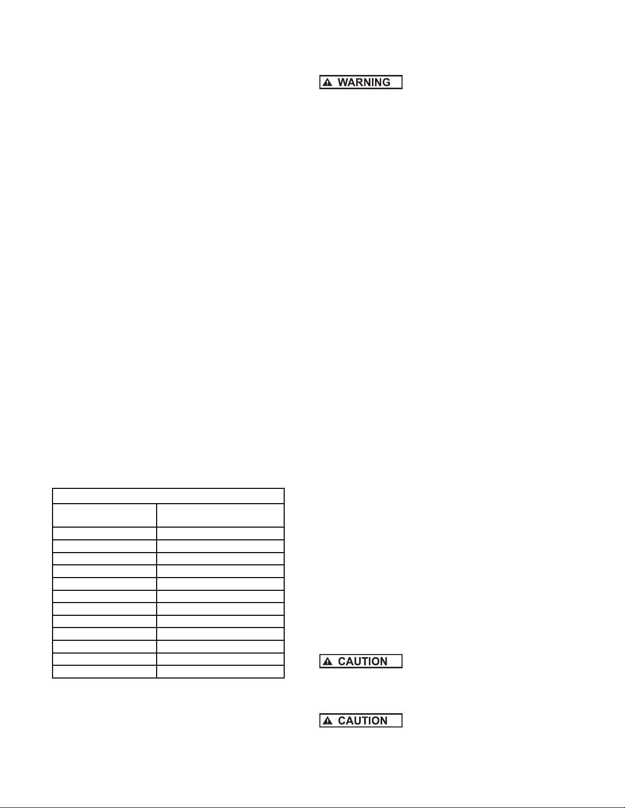
Pressure Setting Guide
System Pressure
(at Pressure Sensor)
25 18
30 21
35 25
40 28
45 32
50 (factory set) 35
55 39
60 42
65 46
70 49
75 53
80 56
Pressure Relief Valve
The pressure relief valve and the discharge outlet need
a flow rating which exceeds the flow capacity of the
installation at the relief pressure. When located in an area
where a water leak or relief valve blow-off may damage
Flint & Walling, Inc. • 95 North Oak Street • Kendallville, IN 46755 • www.flintandwalling.com
Pressure Tank Setting (PSI)
(+/- 2 psi)
© Copyright 2008 Flint & Walling, Inc. All rights reserved.
property connect an adequate drain line to the pressure
relief valve. Run the line to a suitable drain or to an area
where the water will not damage property.
Not providing an adequate relief
valve can cause extreme overpressure which could
result in personal and/or property damage. It is
recommended that you manually activate the valve
monthly to keep it in good working order.
Discharge Pipe
When discharge piping requires an adapter it is
recommended that a stainless steel adapter be used.
Galvanized fittings or pipe should not be connected
directly to the stainless steel discharge head of the
Commander Pro pump as galvanic corrosion may occur.
Barb type connectors should always be double clamped.
Torque arrestors are not required on this installation due
to the soft starting characteristics of the Commander® Pro
100 motor and controller
Check Valve
A check valve is factory installed in the discharge head
of the Commander® Pro 100 submersible pump. This
maintains water within the pipe when the pump is not
operating. For well depths exceeding 125 feet, an
additional check valve should be installed every 125 feet.
Safety Rope
A safety rope eyelet is provided at the discharge of the
pump. It is recommended to attach a nylon safety rope.
This will assist in the removal of the pump and also
prevent loss of the unit in the bottom of the well due to a
loose fitting or pipe deterioration.
Section 3
Pump Installation
1. The following installation instructions as shown
use 160 PSI plastic pipe. Schedule 80 PVC pipe or
galvanized pipe may also be used. If either of these
two types are used, a foot clamp will be required to
hold the PVC or galvanized pipe while connecting the
next length of pipe.
2. Lay the pump a foot or two from the well, pointing
outward (pump discharge away from the well).
3. Lay out plastic pipe, safety rope, hose clamps, piping,
tape, submersible cable, etc.
4. Assembly of all components that go into the well
should be made horizontally on the ground, and then
lowered into the well.
5. Install a stainless steel pipe adapter in the pump
discharge tapping, using teflon tape.
Do not use pipe wrench on any part
of pump except the cast discharge of the pump.
6. Unroll plastic pipe in a straight line away from the
pump.
Be sure working surface is smooth
to avoid damage to the plastic pipe and electric cable.
Cut off sealed end of plastic pipe with a hacksaw.
3
Page 4

7. Position two hose clamps over end of the plastic
pipe. Slide plastic pipe over the plastic pipe adapter
all the way to the shoulder. Position the clamp
tightening screws opposite each other and away from
the motor lead wires to prevent insulation damage.
Tighten the hose clamps and tape clamp tab ends to
pipe with plastic tape.
8. Splice the electric cable to the pump leads.
Heat shrink tubing and Sta-kon connectors are
recommended. It is necessary that the splice be
water tight.
9. Unroll the electric cable along side of the plastic pipe.
Be sure not to damage wire insulation, and that all
kinks are straightened out.
10. Cut the plastic pipe to proper length.
11. Slide cable guards over plastic pipe and submersible
cable. One at 15 ft. above the pump and one every
25 ft. thereafter. Secure guards in position with
retaining clamps or tape.
12. Attach assembly used to plastic pipe with two
stainless steel hose clamps. Tighten clamps securely.
Be sure to assemble the elbow
on the pipe above the well seal. This will prevent
dropping of the pump and piping into the well as you
lower it.
90° Elbow
Adapter
LOWERING PUMP INTO THE WELL
Never support the weight of pump
and piping by the electric cable, as this weight will
break the cable connections.
15. The pump is now ready to be lowered into the well.
A helper will be needed to handle the other end of
the assembly. With the plastic pipe and wire cable
assembly over your shoulder, lift the pump, being
very careful not to kink the plastic pipe.
16. Guide the pump and piping into the well. Protect the
cable when lowering to prevent scraping or damage
by the edge of the well casing.
17. The helper brings his end of the assembly forward as
needed. Keep the pipe, cable, and rope free of grass
or other foreign matter.
Well Seal
Coupling
Adapter
13. Tape electric cable to pipe about every five feet. Use
only 1-1/2 to 2 wraps of tape, so as to allow for some
movement of the cable. Tape spliced connections to
pipe to eliminate rubbing against well casing. Leave
four to five feet of slack, at the upper end to allow for
plastic pipe stretch.
14. Tie safety rope, through eyelet on top of pump. Tape
end of rope to prevent unraveling. Tape safety rope
to pipe every 20 feet. Do not leave any slack in rope.
Tie securely on bottom side of well seal or pitless
adapter and tape end of rope.
18. When the entire assembly is in the well, make sure
well seal is seated. Tighten the four bolts in well seal
evenly.
Section 4
Controller Location Selection
The CP WATER SD100 standard NEMA 1controller is
intended for indoor use and for operation in ambient
temperatures up to 125° F (50° C). For outdoor
installations, a system with a NEMA 4 rated controller
must be used. (Models with 7th and 8th characters
of “N4”). To ensure maximum weather protection, the
unit must be mounted vertically with the cover properly
aligned and secured with all lid screws. The following
recommendations will help in selection of the proper
location of the CP WATER SD100 unit:
Flint & Walling, Inc. • 95 North Oak Street • Kendallville, IN 46755 • www.flintandwalling.com
© Copyright 2008 Flint & Walling, Inc. All rights reserved.
4
Page 5

1. A tank tee is recommended for mounting the tank,
pressure sensor, pressure gauge, and pressure relief
valve at one junction. If a tank tee is not used, the
pressure sensor should relocated within 6 ft. (1.8
meters) of the pressure tank to minimize pressure
fluctuations. There should be no elbows between the
tank and pressure sensor.
2. The unit should be mounted on a sturdy supporting
structure such as a wall or supporting post please account for the fact that the unit weighs
approximately 17 lbs. for NEMA 1 models and 22.0
lbs. for NEMA 4 models.
3. The electronics inside the CP WATER SD100 are aircooled. As a result, there should be at least 6 inches
of clearance on each side and below the unit to allow
room for air flow.
There should be at least 6 inches of
clearance on each side and below the unit to allow
room for proper air flow. There are to be no elbows
between the tank and pressure switch.
4. The CP WATER SD 100 should only be mounted
with the wiring end oriented downward. The controller
should not be placed in direct sunlight or other
locations subject to extreme temperatures or humidity
(mounting location should not be subjected to
freezing conditions or condensation).
5. The mounting location should have access to 230V
electrical supply and to the submersible motor wiring.
WIRE SIZING
Maximum wire lengths connecting the CP100 controller
to the main circuit box. (Based on 3% voltage drop at
230V)
Copper Wire Size (AWG) 12* 10 86432
Maximum Length (Feet) 85 140 220 345 550 680 895
*Wire with 90° C insulation only.
Maximum wire lengths connecting the motor to
the CP100 controller
Copper Wire Size (AWG) 14 12 10 8 6
Maximum Length (Feet) 320 510 810 1280 2010
Due to the inherent voltage changing
characteristics of variable frequency drives (VFD), there
is additional stress placed on the insulation of the wire
between the controller and the motor compared to a
standard pump system. Extra care must be taken when
using Unjacketed Flat Parallel Pump Cable to ensure that
the insulation on each of the separated wires is the same
thickness. Care must also be taken to ensure a proper
seal with shrink tubing on any splices. Failure to take
these precautions can lead to “wire burn through” that will
shut down the system. Under these circumstances, no
permanent damage usually occurs to the controller or motor.
For further details call Technical Support at
1-800-742-5040.
IL0837
SEPARATED WIRE
1. NOTE: DO NOT USE ALUMINUM WIRE.
2. Use 20 Amp circuit breaker for 230V supply
Controller Installation Procedure - SD100
1. Disconnect electrical power at the main breaker
2. Drain the system (if applicable)
3. Install pressure sensor - the pressure sensor has a
1/4 - 18 National Pipe Thread (NPT) connection.
4. Remove the CP WATER SD100 cover by removing
the three lid screws. Install the unit to the wall using
three mounting screws (not included).
Wiring Connections
1. Verify that the power has been shut off at the main
breaker.
2. Verify that the dedicated branch circuit for the CP
WATER SD100 is equipped with a 20 AMP circuit
breaker.
3. Remove the CP WATER SD100 lid.
4. Feed the motor leads through the opening on the
bottom right side of the unit and connect them to the
terminal block positions marked (green ground wire),
Red (Black) Yellow (Brown) and Black (Blue)
5. Feed the 230V power leads through the larger
opening on the bottom left side of the CP WATER
SD100 controller and connect them to the terminals
marked L1, GND, and L2 .
6. Feed the pressure sensor leads through the smaller
opening on the bottom left side of the CP WATER
SD100 unit and connect the red and black leads to
the terminals marked “1” and “2” (interchangeable)
with a small screwdriver (provided).
7. Use the appropriate strain relief or conduit
connectors.
Flint & Walling, Inc. • 95 North Oak Street • Kendallville, IN 46755 • www.flintandwalling.com
© Copyright 2008 Flint & Walling, Inc. All rights reserved.
5
Page 6

8. Replace the cover. Do not over-tighten the screw.
9. Connect the other end of the pressure sensor cable
with the two spade terminals to the pressure sensor.
The connections are interchangeable.
Remove rubber end cap
to adjust pressure. Use
7/32” allen wrench
Pressure sensor
boot
IL0026
A 10 foot section of cable is provided with the CP
WATER SD100 to connect to the pressure sensor.
Lengths of up to 100 feet can be used, provided the
appropriate shielded cabling is used. Consult the
factory for proper cable specification.
10. Set the pressure tank pre-charge to 70% of the
desired water pressure setting. To check the tank’s
pre-charge, de-pressurize the water system by
opening a tap. Measure the tank pre-charge with a
pressure gauge at its inflation valve and make the
necessary adjustments.
11. The pressure sensor communicates the system
pressure to the CP WATER SD100 controller. The
sensor is preset at the factory to 50 psi, but can
be adjusted by the installer using the following
procedure:
a. Remove the rubber end-cap.
b. Using a 7/32” Allen wrench (provided), turn the
adjusting screw clockwise to increase pressure
and counter-clockwise to decrease pressure. The
adjustment range is between 25 and 80 psi (1/4
turn = approximately 3 psi).
c. Replace the rubber end cap.
d. Reset the pressure tank pre-charge to the
appropriate pressure
12. Cover the pressure sensor terminals with the rubber
boot provided.
Start-Up Operation
Apply power to the controller. A steady green light
indicates that the CP WATER SUBDRIVE 100 has power
but the pump is not running. The green light will flash
continuously when the pump is running.
NOTE: Conventional private water systems intermittently
fill a pressure tank as commanded by a standard pressure
switch (e.g. 30 - 50 psi). The CP WATER SD100 maintains
a constant pressure at the pressure sensor up to the
maximum capability of the motor and pump. Although
the pressure is constant at the pressure sensor, pressure
drops may be noticeable in other areas of the home when
additional taps are opened. This is due to limitations in the
plumbing and will be more pronounced the further the taps
are from the pressure sensor. This would be true of any
system, and if observed, should not be interpreted as a
failure in the performance of the CP WATER SD100.
Flint & Walling, Inc. • 95 North Oak Street • Kendallville, IN 46755 • www.flintandwalling.com
© Copyright 2008 Flint & Walling, Inc. All rights reserved.
6
Page 7

SYSTEM TROUBLESHOOTING
Should an application or system problem occur, built-in diagnostics will protect the system. The red “FAULT” light on the
front of the CP WATER SD100 controller will flash a given number of times to indicate the nature of the fault. In some
cases, the system will shut itself off until corrective action has been taken. Fault codes and the recommended corrective
action for each are listed in the following table.
# of
Flashes
1
2
3
4
5
6
Fault Possible Cause Corrective Action
Motor underload
Under voltage
Locked pump
Open circuit
Short circuit
Overpumped or dry well. Worn pump.
Broken motor shaft. Blocked pump or
screen
Low line voltage
Motor/pump misaligned. Abrasives or sand
bound pump
NOT USED
Loose connection. Defective motor or
cable
Defective cable, splice or motor
Wait for well to recover and automatic restart timer
to time out. If the problem does not correct, check
motor and pump. See description of “Smart Reset”
below troubleshooting chart.
Check for loose connections. Check line voltage.
Report low voltage to the power company. Unit
will start automatically when the proper power is
supplied.
Unit will attempt to free a locked pump. If
unsuccessful, check the motor and pump.
Check motor wiring. Make certain all connections
are tight. Make certain proper motor is installed.
Cycle input power* to reset.
Check motor wiring. *Cycle input power to reset.
7
*”Cycle input power” means, turn the power off until both lights fade off and then apply power again.
Overheated
controller
High ambient temperature. Direct sunlight
exposure. Obstructed air flow.
This fault automatically resets when the
temperature returns to a safe level.
Description Part Number
Pressure Switch 020627
100’ Pressure Switch Cord 020628
Controller - Standard 023045
Controller - NEMA 4 023046
Motor 137462
Pump end for CP10007LT (N4LT) CP10007RP
Pump end for CP10010LT (N4LT) CP10010RP
Pump end for CP10019LT (N4LT) CP10019RP
Pump end for CP10027LT (N4LT) CP10027RP
Pump end for CP10035LT (N4LT) CP10035RP
Flint & Walling, Inc. • 95 North Oak Street • Kendallville, IN 46755 • www.flintandwalling.com
© Copyright 2008 Flint & Walling, Inc. All rights reserved.
7
Page 8

TROUBLESHOOTING GUIDE
Symptom Possible Cause Corrective Action
Water flow rate is not as high
as expected
Excessive pressure
fluctuations
Motor runs continuously with
no flow demand from the
house.
Motor is running backwards.
Temperature in the controller is
too high. If the controller’s heat
exchanger becomes too hot, the
controller will reduce the speed
of the pump to lower the power
consumption.
Pump capacity cannot supply the
demand
Waterlogged tank.
Pressure tank is too small for flow
rating of the pump.
Leak in the pitless adapter.
Leak in the household or outdoor
plumbing.
Switch two of the three wires leading from the
controller to the motor (3-phase motor).
Make sure there is at least 6 inches of room
around the controller for movement of air.
Use pump with higher flow rating (if head
requirement is still satisfied).
Check tank for bladder damage - replace if
necessary.
Reset the tank pre-charge pressure (should be
70% of pressure sensor setting).
Use larger tank (4 gal tank minumum).
Re-seat the pitless adapter
Check for leaky faucets, valves and pipe fittings
and repair.
Smart Reset
If a motor underload fault condition occurs, the most likely
cause is an overpumped or dry well. To allow the well to
recover, the CP WATER SD100 will wait 30 seconds to 5
minutes, determined by duration of the previous run time,
before restarting the motor. For example the first time the
fault occurs, the CP WATER SD100 will wait 30 seconds
before attempting to restart the pump. If the system would
then run for 1 minute and an underload fault reoccurs, the
controller will wait 4 minutes before attempting to restart
the pump. This schedule allows for the minimum off-time
possible based on the recovery time of the well.
TOLL FREE HELP LINES:
Flint & Walling, Inc. . . . . . . . . . . . . . . . . . . . . . . 800-345-9422
Franklin Electric Service Hotline . . . . . . . . . . . 800-348-2420
Flint & Walling, Inc. • 95 North Oak Street • Kendallville, IN 46755 • www.flintandwalling.com
© Copyright 2008 Flint & Walling, Inc. All rights reserved.
020324
8
 Loading...