

Page 1
OWNERS GUIDE TO INSTALLATION
AND OPERATION
FW0078
0310
Supersedes
0110
READ THESE INSTRUCTIONS CAREFULLY
Read these installation instructions in detail before installing your pump. Be sure to check the
following:
1. Be certain the motor is connected for the correct line voltage being used (check motor
nameplate).
2. Be certain the pump is completely primed before starting. Otherwise damage may occur to the
seal.
Every pump is tested before leaving the factory, and its performance depends largely on the
installation.
END SUCTION CENTRIFUGAL PUMPS
IL0412
GENERAL SAFETY INFORMATION
1. Follow all local electrical and safety codes, as
well as the National Electrical Code (NEC) and
the Occupational Safety and Health Act (OSHA).
2. Replace damaged or worn wiring cord
immediately.
3. Do not kink power cable and never allow the
cable to come in contact with oil, grease, hot
surfaces or chemicals.
4. Protect the power cable from coming in contact
with sharp objects.
5. Be careful when touching the exterior of an
operating motor - it may be hot enough to be
painful or cause injury.
6. Make certain that the power source conforms
to the requirements of your equipment.
7. Always disconnect power source before
performing any work on or near the motor or
its connected load. If the power disconnect
point is out-of-sight, lock it in the open position
and tag it to prevent unexpected application
of power. Failure to do so could result in fatal
electrical shock.
95 North Oak Street • Kendallville, IN 46755 • Copyright © 2010. All rights reserved.
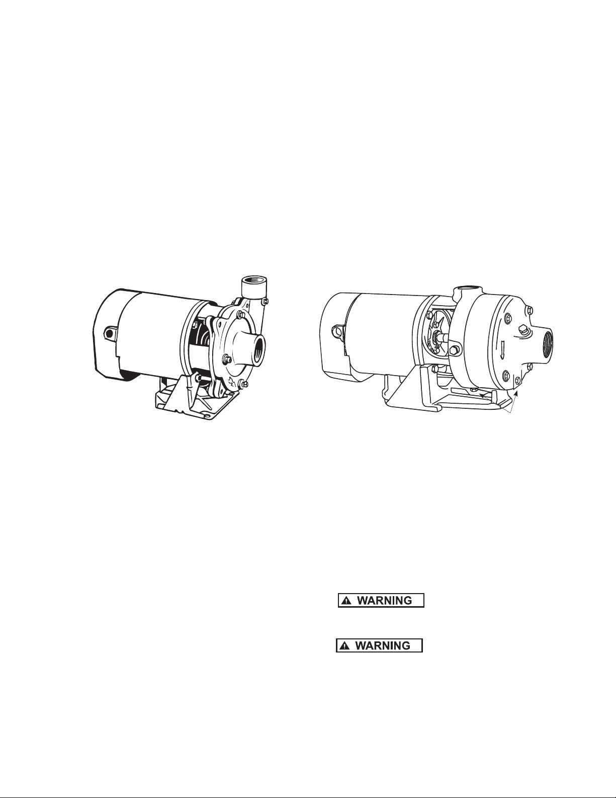
Drain Plug
Figure 2 - CJ101 SeriesFigure 1 - CJ103 Series
8. Do not handle the pump with wet hands or
when standing in water as fatal electrical shock
could occur. Disconnect main power before
handling unit for ANY REASON!
9. Unit must be securely and adequately
electrically grounded. This can be
accomplished by wiring the unit to a ground
metal-clad raceway system or by using a
separate ground wire connected to the bare
metal of the motor frame or other suitable
means.
10.
pump has not been investigated for use in
swimming pool areas.
11.
chemicals known to the State of California
to cause cancer and birth defects or other
reproductive harm.
NOTE: Pumps with the “CSA” mark are tested to
UL standard UL778 and certified to CSA standard
C22.2 No. 108.
1
Risk of electric shock. This
This product contains
130441
IL0201
Page 2
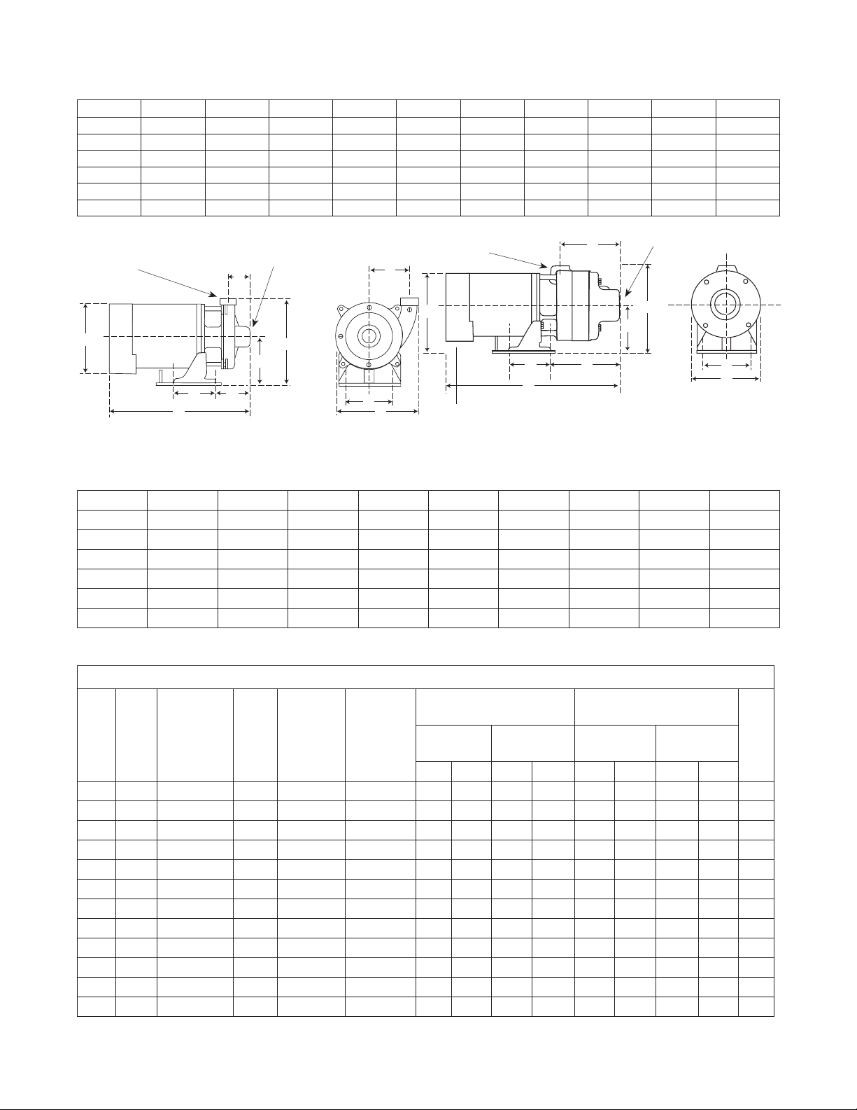
Dimensions (In Inches) CJ103 Series Chart A
HP A B C D E F G H J K
1/3 4 4-5/8 3-11/16 4-13/16 9-3/16 2-1/2 8-1/4 8-1/8 13-1/4 3-7/8
1/2 4 4-5/8 3-11/16 4-13/16 9-3/16 2-1/8 8-1/4 8-1/8 13-1/2 3-7/8
3/4 4 4-5/8 3-11/16 4-13/16 9-3/16 2-1/8 8-1/4 8-1/8 14 3-7/8
1 4 4-5/8 3-11/16 4-13/16 9-3/16 2-1/8 8-1/4 8-1/8 14-1/2 3-7/8
1-1/2 4 4-5/8 3-11/16 4-13/16 9-3/16 2-1/8 8-1/4 8-1/8 15-1/8 3-7/8
2 4 4-5/8 3-11/16 4-13/16 9-3/16 2-1/8 8-1/4 8-1/8 15-5/8 3-7/8
1-1/2” Suction
F
1-1/4” Discharge
1-1/2” Suction
F
1-1/4” Discharge
K
E
D
B
G
IL0395
H
A C
J
Figure 3 - CJ103 Single Stage Booster Pump
E
D
IL0396
H
A
J
B
G
Figure 4 - CJ101B Two and Three Stage Booster Pump
C
CJ101 Series Chart B
HP A B C D E F G H J
3/4 4 4-5/8 7-9/16 4-13/16 8-3/4 6-1/4 7 8-1/8 17-7/8
1 4 4-5/8 7-9/16 4-13/16 8-3/4 6-1/4 7 8-1/8 18-3/8
1-1/2 4 4-5/8 7-9/16 4-13/16 8-3/4 6-1/4 7 8-1/8 19
2 4 4-5/8 7-9/16 4-13/16 8-3/4 6-1/4 7 8-1/8 19-1/2
2 * 4 4-5/8 9-7/16 4-13/16 8-3/4 8-1/8 7 8-1/8 21-3/8
3 * 4 4-5/8 9-7/16 4-13/16 8-3/4 8-1/8 7 8-1/8 21-3/8
(*) Three Stage
Motor Data Chart C
MOTOR
HP PH VOLTS HZ RPM
1/3 1 115/230 60 3450 11 5 V 8.6 4.3 — — 26.0 13.0 — — K
1/2 1 115/230 60 3450 11 5 V 13.0 6.5 — — 36.0 18.0 — — K
3/4 1 115/230 60 3450 11 5 V 14.0 7.0 — — 52.0 26.0 — — K
1 1 115/230 60 3450 230V 18.0 9.0 — — 70.0 39.0 — — L
1-1/2 1 115/230 60 3450 230V 21.0 10.5 — — 98.0 49.0 — — J
2 1 115/230 60 3450 230V 25.0 12.5 — — 116.0 58.0 — — H
3 1 230 60 3450 230V — 13.5 — — — 53.0 — — D
3/4 3 208-230/460 60/50 3450/2850 230V — — 3.5 1.75 — — 19.0 9.5 K
1 3 208-230/460 60/50 3450/2850 230V — — 4.5 2.25 — — 26.9 13.5 K
1-1/2 3 208-230/460 60/50 3450/2850 230V — — 5.7 2.85 — — 33.5 16.8 K
2 3 208-230/460 60/50 3450/2850 230V — — 7. 4 3.0 — — 44.0 22.0 K
3 3 208-230/460 60 3450 230V — — 9.8 4.9 — — 48.0 24.0 D
VOLTAGE
(FACTORY)
CONNECT.
SERVICE FACTOR MOTOR
AMPS
THREE
PHASE
11 5 V 230V 230V 460V 11 5 V 230V 230V 460V
PHASE
LOCKED ROTOR AMPS
SINGLE
PHASE
THREE
PHASE
KVASINGLE
2
95 North Oak Street • Kendallville, IN 46755 • Copyright © 2010. All rights reserved.
Page 3
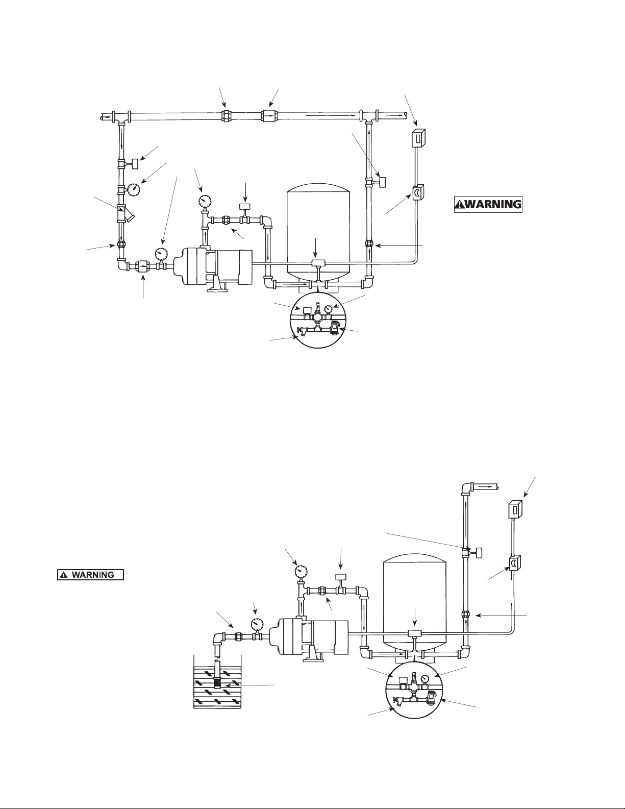
IL0413
IL0414
Street Supply
Line Strainer
or Filter
(Optional)
Union
Gate/Ball Valve
(Normally Open)
Check Valve
Typical Installations
Union
Pressure
Gauge
Gate/Ball Valve
(Normally Open)
Union
Pressure Switch
Drain
Check Valve
Gate/Ball Valve
(Normally Open)
Pressure Tank
Pressure
Switch
Main Power Box
Fuse Box
or Switch
Union
Pressure Gauge
Pressure Relief Valve
To size pressure tank
properly, match the
drawdown of the tank
to the capacity of the
pump.
(*) For manual
operation, omit the
pressure tank and
pressure switch. Wire
motor direct to fuse
box.
Install
a pressure relief valve
on any installation
where pump pressure
can exceed the pressure
tank’s maximum working
pressure or on systems
where the discharge
line can be shut off or
obstructed. Extreme
over pressure can result
in personal injury or
property damage.
Figure 5
To size pressure tank
properly, match the
drawdown of the tank
to the capacity of the
pump.
(*) For manual
operation, omit the
pressure tank and
pressure switch. Wire
motor direct to fuse
box.
Install
a pressure relief valve
on any installation
where pump pressure
can exceed the pressure
tank’s maximum working
pressure or on systems
where the discharge
line can be shut off or
obstructed. Extreme
over pressure can result
in personal injury or
property damage.
Union
Vacuum
Gauge
Pressure
Gauge
Pressure Switch
Foot Valve
with Strainer
Gate/Ball Valve
(Normally Open)
Union
Drain
Pressure Tank
Pressure
Switch
Main Power Box
Fuse Box
or Switch
Union
Pressure Gauge
Pressure Relief Valve
Figure 6
3
95 North Oak Street • Kendallville, IN 46755 • Copyright © 2010. All rights reserved.
Page 4
Pump Performance Chart D
Single
Phase
Model No.
CJ103031 - 1/3 1 41 30 10 27 10 0 200°F
CJ103051 CJ103053 1/2 1 48 40 27 30 10 0 200°F
CJ103071 CJ103073 3/4 1 62 58 46 31 33 10 0 200°F
CJ103101 CJ103103 1 1 70 66 58 48 34 40 10 0 200°F
CJ103151 CJ103153 1-1/2 1 * 75 70 61 51 36 44 10 0 200°F
CJ103201 CJ103203 2 1 * * 79 77 68 57 45 10 0 200°F
CJ101B071 CJ101B073 3/4 2 * * 32 29 25 22 5 53 160 200°F
CJ101B101 CJ101B103 1 2 * * 35 32 29 27 23 3 62 160 200°F
CJ101B151 CJ101B153 1-1/2 2 * * 42 39 37 34 28 19 68 160 200°F
CJ101B201 CJ101B203 2 2 * * 45 44 43 40 34 26 70 160 200°F
CJ101C201 CJ101C203 2 3 * * 42 41 40 38 35 31 27 20 7 93 160 200°F
CJ101C301 CJ101C303 3 3 * * 51 50 49 43 41 40 35 29 21 95 160 200°F
CJ101P071 CJ101P073 3/4 2 * * 31 28 23 20 48 160 160°F
CJ101P101 CJ101P103 1 2 * * 34 31 30 29 19 60 160 160°F
CJ101P151 CJ101P153 1-1/2 2 * * 46 44 41 37 31 14 61 160 160°F
CJ101P201 CJ101P203 2 2 * * 45 44 42 39 31 21 65 160 160°F
CJ101D201 CJ101D153 2 3 * * 41 40 38 37 33 29 24 17 89 160 160°F
CJ101D301 CJ101D303 3 3 * * * 46 45 45 42 38 33 27 18 93 160 160°F
To convert to feet of head, multiply by 2.31.
* Operation of pump in this range may result in m otor damage.
Do not exceed the maximum case pressure and maximum liquid temperature rating of the pump.
Suction & Discharge Tapping: 1-1/2” X 1-1/4”
Motor Voltage: Single phase: 1/3 - 115V; 1/2 thru 2 HP - 115/230V; 3 HP - 230V, 60HZ
Three phase: 1/2 thru 2 HP - 208-230/460V - 50/60HZ
3 HP - 208-230/460V - 60HZ
Three
Phase
Model No.
HP Stage
15 20 25 30 35 40 50 60 70 80 90
THERMOPLASTIC IMPELLER MODELS
GPM at Total Pressure in PSI
Press.
BRASS IMPELLER MODELS
Max.
PSI
Max.
Case
Press.
PSI
Max.
Liquid
Temp.
INSPECTION AND STORAGE
When unpacking the unit, inspect carefully for any
damage that may have occurred during shipment.
If the unit is received sometime before it can be
used, it should be inspected, recrated and stored
in a dry location.
LOCATION
IMPORTANT: In installations where property
damage might result from an inoperative or
leaking pump due to power outages, discharge
line blockage or any other reason, a back-up
system (s) and/or warning system (s) should be
used.Install a gate valve and union in the suction
and discharge lines. For removal of the pump for
service, close the gate valve and disconnect the
union.
1. Locate pump as close to the fluid source as
possible.
2. Place unit where the motor electrical
components and piping are protected from the
weather and extremes of heat, humidity and
below freezing temperatures.
3. Mount unit in a dry location that is easily
accessible for inspection and maintenance. If
a dry location is not available, mount it on a
foundation well above the wet floor.
4. Allow ample clearance around unit for free air
circulation.
5. CJ103 Series pumps incorporate a discharge
port on the pump casing that can be adjusted
in 90 increments. If necessary, adjust the
discharge port to accommodate the specific
application. Pump performance will not be
affected by the position of the discharge port.
SUCTION LIMITATIONS
1. Units are non self-priming. Normally after
being primed the total suction lift of the pump
is 25 feet. Suction lift varies depending upon
elevation (altitude) and water temperature. See
Practical Suction Lift chart.
2. Where liquids at or near their boiling points
are being handled, the supply must be located
above the suction, so that the available NPSH
will be greater than that required by the unit.
4
95 North Oak Street • Kendallville, IN 46755 • Copyright © 2010. All rights reserved.
Page 5

Practical Suction Lifts at Various Elevations and
IL0415
Water Temperatures in Degrees Fahrenheit
Altitude 60º 80º 100º 120º 140º 160º 180º 200º
Sea Level -22 -21 -20 -18 -15 -10 -4 +5
2000 -20 -19 -18 -16 -12 -7 -1 +8
4000 -17 -16 -15 -13 -10 -4 +2 +12
6000 -15 -14 -13 - 11 -7 -2 +6 +16
8000 -13 -12 -10 -8 -4 +2 +9 —
10000 -10 -9 -8 -6 -2 +4 +13 —
This table gives the maximum permissible suction lift or
the minimum head permitted on the suction side of a pump
at various altitudes and liquid temperatures. A minus sign
before a number indicates suction lift. A plus sign before a
number indicates minimum head. These figures are to be
used as a guide.
PIPING
1. Use galvanized piping, rigid plastic or other
suitable pipe that will not collapse under
suction or rupture due to pressure.
2. The diameter of the suction and discharge pipe
should be no smaller than the corresponding
tappings of the pump (see Figure 3 & 4). If long
runs are encountered larger pipe should be
used. Smaller pipe will reduce the capacity of
the pump.
3. All joints and connections should have Teflon
tape or pipe sealing compound (male threads
only) applied and drawn up tightly.
The entire system must be air and
water tight for efficient operation.
PUMP INSTALLATION
Refer to Figures 5, 6, and 7 for typical installations.
Both the suction and discharge pipe should be
supported at a point near the pump to avoid
strains being placed on the pump.
Pressure Gauge
Priming Plug
Discharge Tee
Suction Pipe Installed with
Gradual Rise to Pump Inlet
Level
Rigid
Foundation
Figure 7
Pipe
Support
5. On suction lift installations, a foot valve located
in the water or a check valve located as close
to the water as possible will reduce priming
time of the pump and help maintain prime. A
strainer must be used on the suction line to
filter out dirt and debris.
6. A priming tee installed in the pump discharge
port allows water to be poured into the pump
case and suction piping, which is required for
priming on suction lift installations.
7. Install a gate valve and union in the suction and
discharge lines. For removal of the pump for
service, close the gate valve and disconnect the
union.
Do not use a globe valve or other
restricting type of valve at the discharge. This will
seriously restrict the capacity of the pump.
8. Pressure Gauges - Properly sized vacuum or
pressure gauges can be installed in both the
suction and discharge pipe. The gauges will
enable observation of the pump’s performance
as well as detecting cavitation, vapor binding or
other unstable operation.
1. If the pump is used as part of a permanent
installation, secure to a rigid foundation with
appropriate fasteners.
2. Locate the pump as close to the water as
possible, keeping the suction pipe as short as
conditions permit.
3. Avoid dips or pockets in offset piping or air
will accumulate at high points which will make
priming difficult.
4. The suction pipe should slope upward to the
pump inlet. A horizontal suction line must have
a gradual rise to the pump.
95 North Oak Street • Kendallville, IN 46755 • Copyright © 2010. All rights reserved.
Use only components that are rated
higher than shut-off pressure of the system. Do not
exceed the pump’s maximum case pressure as listed in
the following table.
capacity must be installed on any installation where
the pump pressure can exceed the pressure tank’s
maximum working pressure or on systems where
the discharge line can be shut-off or obstructed.
Not providing a relief valve can cause extreme over
pressure which could result in personal injury and/or
property damage.
5
Models
CJ103 100 PSI
CJ101 160 PSI
A pressure relief valve of adequate
Maximum Case
Pressure
Page 6

ELECTRICAL
nameplate or figures 8, 9 & 10.
Ground motor before connecting
to electrical power supply.
Connect the motor frame to
Hazardous voltage.
Can shock, burn
or cause death.
Failure to follow
warnings can
cause fatal or
severe shock
hazard or
equipment failure.
equipment grounding conductor by
using green screw. Do not connect
green ground wire to any of the motor
leads.
Do not ground to a gas supply
line.
Turn off power to motor before working on electrical
connections.
Supply voltage must be within ±10% of nameplate
voltage. If in doubt consult a licensed electrician.
Use wire size specified in wiring Chart E. If possible,
connect pump to a separate branch circuit with no other
appliances on it. If wiring diagram on motor model plate
differs from diagram shown in figures 8, 9 & 10, follow
diagram on motor.
All wiring should be performed by a qualified electrician
and in accordance with the national and local electric
codes.
WIRING
1. Motor voltages will vary depending upon the
motor horsepower and phase. Refer to the
motor nameplate and the Motor Data Chart
(Chart C) for voltage and electrical data.
Make certain that the power supply
conforms to the electrical specifications of the motor
supplied. Failure to do so may cause premature motor
failure and will void the warranty.
2. To change voltage, remove the rear access
cover, which is held in place with two (2)
screws. For proper electrical connection, refer
to the connection diagram located on the motor
SINGLE PHASE
L1
Y
W
E
H
L
I
L
T
O
E
W
115 VOLTS
LINE
A
G
R
A
Y
L2
B
R
T
E
A
D
N
SINGLE PHASE
L1
Y
W
E
H
L
I
L
T
O
E
W
230 VOLTS
LINE
A
B
G
R
A
Y
L2
R
T
E
A
D
N
IL0180
Replace rear access cover before
starting or operating pump. Failure to do so can result
in personal injury.
MOTOR PROTECTION
1. All single phase motors have built in thermal
protection for all voltages. The overload
protects the motor against burnout from
overload of low voltage, high voltage and other
causes. The device is automatic and resets
itself once the temperature has dropped to
a safe point. Frequent tripping of the device
indicates trouble in the motor or power lines
and immediate attention is needed.
Never examine, make wiring changes
or touch the motor before disconnecting the main
electrical supply switch. The thermal device may have
opened the electrical circuit.
2. Three phase motors do not have a built in
thermal protection. It is recommended that a
properly sized magnetic or manual starter (both
with properly sized heaters) be used with all
three phase motors. Install starters following
instructions of the starter manufacturer. See
Figure 11 for magnetic starter wiring diagram.
3. All motors (single and three phase) should be
equipped with a correctly fused disconnect
switch to provide protection. consult local
or national electric codes for proper fuse
protection based on motor data chart (see
Charts C & E).
PRIMING
1. Before starting any centrifugal pump, it is
absolutely necessary that both the casing and
suction pipe be completely filled with liquid.
This priming can be accomplished by any of
the following methods:
2. When the liquid supply level is above the center
line of the pump, it is primed by opening the
suction and discharge valves. The inflowing
liquid will displace the air and fill the suction
Low Voltage
230V
5
4
7
889
2
1
L
L
2
1
L
3
IL0182
L
High Voltage
460V
566
4
7
23 3
1
L
1
2
9
L
3
Figure 9 - Wiring Diagram for Single Phase
1/3-2 HP
95 North Oak Street • Kendallville, IN 46755 • Copyright © 2010. All rights reserved.
Figure 10 - Wiring Diagram for Three Phase
6
Page 7

line, pump casing, and discharge line up to the
level of supply.
3. Where the pump is operating with suction
lift and the suction line is equipped with a
foot valve, remove the priming plug from the
discharge tee (see Figures 5-8) and fill the
pump body and suction pipe completely with
water. No additional water will be needed for
subsequent start-ups unless the pump body is
drained.
4. After the pump is turned on it will require 2-5
minutes before all air is evacuated from the
suction line and water begins to flow. If there
is no water after 5 minutes, turn the pump off
and check the following:
5. Any air leaks on the suction line must be
eliminated.
6. Suction pipe inlet should be a minimum of 5
feet below the water level.
7. Total suction lift cannot be greater than 25 feet.
8. Any restrictions in the discharge pipe, such as a
closed valve must be eliminated.
NOTE: Unit must be full of liquid before operating.
Never run dry, or against a closed discharge. Dry
running or running unit against a closed discharge
will cause damage to the shaft seal. Do not pump
dirty water or abrasive liquids, otherwise the same
may occur as if running dry.
MOTOR ROTATION
1. Single phase models are one (1) rotation only
(counterclockwise when facing the pump
suction tapping) and cannot be reversed.
Fused
Disconnect
Switch
Lightning
Arrestor
L3
X2
T3
T3
Pressure
Switch
T1
T1
L2
MV W
T2
T2
Motor
L1
03
02
IL0102
#10 or Heavier Copper Ground Wire, Connect
to 10 Ft. Ground Rod or Well Casing
Figure 11 - Magnetic Starter Wiring Diagram Three Phase
2. Proper rotation of pump impeller is critical for
three phase pumps. Pump motor should turn
counterclockwise (CCW) when facing pump
suction tapping. Momentarily “bump” (apply
power for less than a second) the motor to check
for proper rotation. To change rotation on three
phase units, interchange any two (2) incoming
line (power) leads.
IL0416
Figure 12 - Correct Motor Rotation
Chart E
DISTANCE FROM
MOTOR TO FUSE
BOX METER,
OR ELECTRICAL
OUTLET
0-50’ 14 14 12 14 12 14 10 14 10 12 10 12 10 14 14 14 14 14 14 14 14 14 14
50-100’ 14 14 12 14 12 14 10 14 8 12 8 12 10 14 14 14 14 14 14 14 14 14 14
100-150’ 14 14 12 14 10 14 10 12 6 12 6 12 10 14 14 14 14 14 14 14 14 14 14
150-200’ 12 14 12 14 10 12 8 12 * 10 * 10 10 14 14 14 14 12 14 12 14 12 14
200-300’ 12 14 10 14 8 12 6 10 * 10 * 10 8 14 14 12 14 12 14 10 12 10 12
Breaker Size
(Amps)
(*) Not economical to run in 115 volt, use 230 volts
1/3 HP 1/2 HP 3/4 HP 1 HP 1-1/2 HP 2 HP 3 HP 3/4 HP 1 HP 1-1/2 HP 2 HP 3 HP
115V 230V 115V 230V 115V 230V 115V 230V 115V 230V 115V 230V 230V 230V 460V 230V 460V 230V 460V 230V 460V 230V 460V
15 15 20 15 20 15 30 15 30 20 30 20 30 15 15 15 15 15 15 15 15 15 15
95 North Oak Street • Kendallville, IN 46755 • Copyright © 2010. All rights reserved.
MINIMUM COPPER WIRE SIZE CHART (GAUGE)
SINGLE PHASE MOTORS THREE PHASE MOTORS
7
Page 8

MAINTENANCE
Lubrication
The pumps and motors require no lubrication.
The ball bearings of the motor have been greased
at the factory. Under normal operating conditions
they should require no further greasing.
Winterizing your Pump
Cracked pump housings caused by freezing are
not covered by warranty. To protect your pump
from freezing, for best results remove the pump
and store in a warm environment. If pump cannot
be removed from your system, remove both
drain plugs, one on the suction flange and one
at the bottom rear of the pump (see fig 2 in the
instructions.) Allow the water to completely drain
from the pump. Re-install both drain plugs and fill
pump with RV type antifreeze. Antifreeze also acts
as a rust inhibitor. It will help keep rust build up to
a minimum and seals lubricated inside the pump
while it is not in use.
ROTARY SEAL ASSEMBLY REPLACEMENT
Disassembly
When disassembling the pump, care
should be taken not to damage the gaskets. If torn or
damaged, replace with new gasket (see parts list).
1. Remove the four (4) pump through bolts that
connect the mounting ring to the pump body.
Remove the pump body, taking care not to
damage the gasket or o-ring.
2. Remove the impellers. CJ103 Models are
single stage units, having one impeller. Using
a 9/16” open end wrench, hold the motor shaft
flat and unthread the impeller by turning it
counterclockwise. The motor shaft flat area is
located in the middle of the mounting ring.
3. CJ101 models are multi stage units, having
two or more impellers and one or more
intermediate stages. Using an 11/16” open
end wrench on the motor shaft extension
flat, remove the first impeller by turning or
counterclockwise. Remove the intermediate
stage (stages) taking care not to damage the
gasket (gaskets) and unthread the remaining
impellers.
4. Remove the mechanical seal assembly. The
rotary portion of the seal assembly (carbon
ring, Buna-N gasket and spring) will easily slide
off the end of the shaft. The ceramic portion
can be pried out of the rubber seating using
two (2) screwdrivers (see Figure 13).
Reassembly
The precision lapped faces of the
mechanical seal are easily damaged. Handle the
replacement seal carefully. Short seal life will result if
seal faces (ceramic & carbon) are nicked, scratched or
dirty.
1. Clean the seal cavity of the mounting ring and
the motor shaft thoroughly.
2. Apply liquid soap (one drop only) to the outside
of the Buna-N gasket that houses the ceramic
seal seat. With thumb pressure, press the
ceramic seat, polished face up, squarely into
the seal cavity (see Figure 14).
3. If seal does not seat squarely, remove and
reclean the seal cavity. Place a cardboard
washer over the polished seal face and carefully
press into place using a piece of pipe or tubing
(see Figure 15). Discard cardboard washer.
4. Apply liquid soap (one drop only) to the inside
diameter of the rubber drive ring. Slip rubber
drive ring (carbon face down) and the spring
over the shaft.
5. Reassemble the pump by following the reverse
order of the disassembly instructions.
MOTOR REPLACEMENT
1. Nema J motors can be replaced in the field
with any standard Nema J jet pump motor by
referring to the following instructions and the
attached parts list.
Figure 13 - Remove Mechanical Seal
IL0173
95 North Oak Street • Kendallville, IN 46755 • Copyright © 2010. All rights reserved.
IL0168
Figure 14 - Press in Seal
3/4” Pipe
- Press
Carefully
IL0169
Figure 15 - If Necessary, Press with
Cardboard and Pipe
8
NOTE:
Cardboard Washer
Protects Seal Face
Seal
Seal
Cavity
Page 9

2. Follow steps as outlined under Rotary Seal
Replacement to remove the pump body,
diffuser, impeller and rotary seal.
3. Remove bolts that connect the motor to the
mounting ring and pull motor away.
4. Replace motor with standard Nema J jet
pump motor by positioning motor against the
connected at the bottom of the mounting frame
with two (2) 3/8” x 1/2” cap screws.
5. Follow steps of Rotary Seal Assembly to
reassemble the remainder of the pump.
BECAUSE DAMAGE TO THE SHAFT SEAL IS
MOST LIKELY TO OCCUR IN DISASSEMBLY, A
NEW SEAL WILL BE NECESSARY.
mounting frame and assembling with four (4)
3/8” x 3/4” cap screws. The mounting base is
Troubleshooting Chart
Symptom Possible Cause(s) Corrective Action
Little or no
discharge
Loss of suction 1. Air leak in suction line 1. Repair
Pump vibrates
and/or makes
excessive noise
Pump will not start
or run
Pumps leaks at
shaft
1. Pump not primed 1. Prime unit
2. Total head too high 2. Shorten suction lift and/or discharge
head
3. Suction head higher than
3. Lower pump inlet
pump designed for
4. Impeller clogged 4. Clean
5. Incorrect rotation 5. Refer to wiring information
6. Leak in suction line 6. Repair or replace
7. Inadequate foot valve 7. Make needed adjustments
8. Impeller damaged 8. Replace
9. Foot valve or suction line not
9. Submerge lower in water
submerged deep enough in
water
10. Insufficient inlet pressure or
suction head
10. Increase inlet pressure by adding
more fluid to fluid source
11. Wrong size piping 11. Make needed adjustments
12. Casing gasket leaking 12. Replace gasket
13. Suction or discharge line
13. Open
valves closed
2. Suction head too high 2. Lower pump inlet
3. Insufficient inlet pressure or
suction head
3. Increase inlet pressure by adding
more fluid to fluid source
4. Clogged foot valve or strainer 4. Clean or replace
1. Mounting plate or foundation
1. Reinforce
not rigid enough
2. Foreign material in pump 2. Clean
3. Damaged impeller 3. Replace
4. Cavitation present 4. Check suction line for proper size and
be certain valve is open. Remove
excessive loops in suction line
5. Worn motor bearings 5. Replace
6. Bent impeller shaft 6. Replace
1. Improperly wired 1. Refer to wiring diagram
2. Blown fuse or open circuit
2. Replace fuse or close circuit breaker
breaker
3. Loose or broken wiring 3. Tighten connections and replace
broken wiring
4. Impeller clogged 4. Clean
5. Motor shorted out 5. Replace
1. Worn mechanical seal 1. Replace
2. Bent impeller shaft 2. Replace
9
95 North Oak Street • Kendallville, IN 46755 • Copyright © 2010. All rights reserved.
Page 10

CENTRIFUGAL PUMP REPAIR PARTS
“CJ103” SERIES
(For Pricing Refer To Repair Parts Price List)
FORM NO. FW0039
SUPERSEDES 1009
PAGE 4-1A REPAIR PARTS
0110
1
3
10
HP 1/3 1/2 3/4 1 1-1/2 2
STAGE 1 1 1 1 1 1
SINGLE PHASE
BRASS IMPELLER
CJ103031 CJ103051 CJ103071 CJ103101 CJ103151 CJ103201
THREE PHASE
ITEM
BRASS IMPELLER
SINGLE PHASE
PLASTIC IMPELLER
MODEL
NO.
CJ103P031 CJ103P051 CJ103P071 CJ103P101 CJ103P151 CJ103P201
THREE PHASE
PLASTIC IMPELLER
DESCRIPTION
PART
NO.
11Motor, Nema J - 1PH
Motor, Nema J - 3 PH
Motor Access Cover
Screws, Access Cover
‡
Slinger Washer
2
Mounting Ring
3
Hex Hd. Cap Screws 3/8 x 3/4”
4
Seal, Rotary w/Spring
5
Impeller - Brass
5A
Impeller - Plastic
5B
Clearance Ring
6
Ring, Square Cut †
7
Body Assembly - Brass Impeller
Body Assembly - Plastic Impeller
‡
Suction Clearance Ring-Brass
8
Pipe Plugs, 1/8” NPT
910Hex Hd. Cap Screws 3/8 x 1”
Base
(*) Standard hardware item
(‡) Not shown
(†) For pumps with paper gasket, replace with part number 127782
(
∆) Kit Includes: Access Cover, Screws & Wiring Diagrams
021301R
021302
126905
134107
*
131100
132583
021439
*
*
125855
95 North Oak Street • Kendallville, IN 46755 • Copyright © 2010. All rights reserved.
98J103
—
1
2
1
1
4
1
130403A
133426
N/A
1
127870
1
127869A
4
4
1
5A
2
4
6
9
5B
7
5
8
IL0417
CJ103053 CJ103073 CJ103103 CJ103153 CJ103203
CJ103P053 CJ103P073 CJ103P103 CJ103P153 CJ103P203
QTY.
98J105
98J305
1
2
1
1
4
1
126900A
139222
138138
1
127870
1
127869A
4
4
1
98J107
98J307
1
2
1
1
4
1
127805
021280
134240
1
127780
1
N/A
4
4
1
98J110
98J310
1
2
1
1
4
1
127804
135248
134240
1
127780
1
N/A
4
4
1
98J115
98J315
1
2
1
1
4
1
127806
021279
134240
1
127780
1
N/A
4
4
1
98J120
98J320
127848
127780
10
1
2
1
1
4
1
N/A
N/A
1
N/A
N/A
4
4
1
Page 11

FORM NO. FW0040
0310
SUPERSEDES 0110
PAGE 4-2A REPAIR PARTS
CENTRIFUGAL PUMP REPAIR PARTS
“CJ101” SERIES
(For Pricing Refer To Repair Parts Price List)
1
2
4
13
12
3
6
5
8
9
Detail of
Intermediate Stage
Assembly
Square
Cut Ring
HP 3/4 1 1-1/2 2 2 3
STAGE 2 2 2 2 3 3
SINGLE PHASE - BRASS IMPELLER
ITEM
THREE PHASE - BRASS IMPELLER
SINGLE PHASE - PLASTIC IMPELLER
THREE PHASE - PLASTIC IMPELLER
MODEL
NO.
CJ101B071 CJ101B101 CJ101B151 CJ101B201 CJ101C201 CJ101C301
CJ101B073 CJ101B103 CJ101B153 CJ101B203 CJ101C203 CJ101C303
CJ101P071 CJ101P101 CJ101P151 CJ101P201 CJ101D201 CJ101D301
CJ101P073 CJ101P103 CJ101P153 CJ101P203 CJ101D203 CJ101D303
DESCRIPTION PART NO. QTY
11Motor, Nema J - 1 PH
Motor, Nema J - 3 PH
Motor Cover w/Screws
Screws, Cover
‡
Slinger Washer
2
Shaft
3
Mounting Ring
4
Hex Hd. Cap Screws 3/8 x 3/4”
5
Seal, Rotary w/Spring
6
Impeller, Brass
6
Impeller, Thermoplastic
7
Spacer, Shaft
8
Gasket
9
Intermediate Stage Assy-Brass**
9
Intermediate Stage Assy-Plastic**
‡
Suction Clearance Ring
‡
Hub Clearance Ring
‡
Square Cut Ring Interm. Stg.
10
Suction Flange Assembly-Brass
10
Suction Flange Assembly-Plastic
‡
Suction Clearance Ring
‡
Suction Bearing
11
Pump thru Bolts 3/8” x 3-1/4”
11
Pump thru Bolts 3/8” x 5”
12
Base w/ Bolts 3/8” x 1-1/4”
13
1/4" NPT Plug
(*) Standard hardware item
(†) For quantity required — See number of stages
(‡) Not shown
(**) Includes two castings, square cut ring, suction and hub clearance ring - See Detail Drawing
(∆) Kit Includes: Access Cover, Screws & Wiring Diagrams
021301R
021302
126905
125204
*
131100
133380
130968
131239B
023405
130957
131282
020240
125227A
023404
130957
020053
*
020054
*
98J107
98J307
1
2
1
135279A
1
2
1
†135280A
†133425
1
2
1
1
1
1
1
1
1
1
1
4
-1
4
98J110
98J310
1
2
1
135279A
1
2
1
†135281A
†133427
1
2
1
1
1
1
1
1
1
1
1
4
-1
4
8
98J115
98J315
135279A
†126900A
†139180
7
IL0159
1
2
1
1
2
1
1
2
1
1
1
1
1
1
1
1
1
4
-1
4
6
98J120
98J320
1
2
1
135279A
1
2
1
†126901A
†128472
1
2
1
1
1
1
1
1
1
1
1
4
-1
4
10
11
98J120
98J320
1
2
1
136612A
1
2
1
†139126A
†139221
2
3
2
2
2
2
2
1
1
1
1
-4
1
4
13
13
98J630
98J330
1
2
1
136612A
1
2
1
†136951A
†139104
2
3
2
2
2
2
2
1
1
1
1
-4
1
4
11
95 North Oak Street • Kendallville, IN 46755 • Copyright © 2010. All rights reserved.
 Loading...