

Page 1
OWNERS GUIDE TO INSTALLATION
AND OPERATION
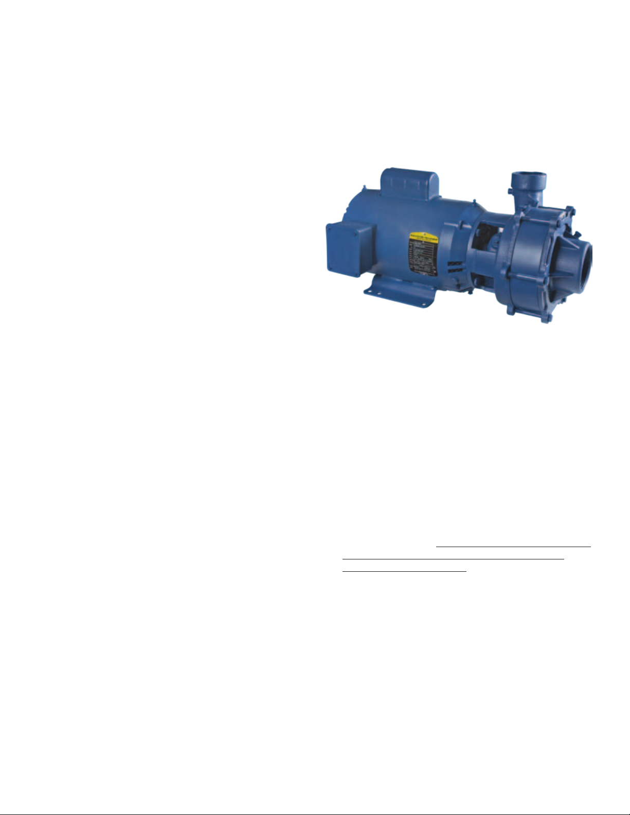
END SUCTION CENTRIFUGAL PUMPS
READ THESE INSTRUCTIONS CAREFULLY
Read these installation instructions in detail before
installing your pump. Be sure to check the following:
1. Be certain the motor is connected for the correct
line voltage being used (check motor nameplate).
2. Be certain the pump is completely primed before
starting. Otherwise damage may occur to the
seal.
Every pump is tested before leaving the factory, and
its performance depends largely on the installation.
FW0300
0111
Supersedes
0309
GENERAL SAFETY INFORMATION
1. Follow all local electrical and safety codes, as
well as the National Electrical Code (NEC) and the
Occupational Safety and Health Act (OSHA).
2. Replace damaged or worn wiring cord immediately.
3. Do not kink power cable and never allow the cable
to come in contact with oil, grease, hot surfaces, or
chemicals.
4. Protect the power cable from coming in contact with
sharp objects.
5. Be careful when touching the exterior of an
operating motor - it may be hot enough to be painful
or cause injury.
6. Make certain that the power source conforms to the
requirements of your equipment.
7. Always disconnect power source before performing
any work on or near the motor or its connected load.
If the power disconnect point is out-of-sight, lock it in
the open position and tag it to prevent unexpected
application of power. Failure to do so could result in
fatal electrical shock.
8. Do not handle the pump with wet hands or when
standing in water as fatal electrical shock could
occur. Disconnect main power before handling unit
for ANY REASON!
9. Unit must be securely and adequately electrically
grounded. This can be accomplished by wiring the
unit to a ground metal-clad raceway system or by
using a separate ground wire connected to the bare
metal of the motor frame or other suitable means.
10. WARNING: Risk of electric shock. This pump has
not been investigated for use in swimming pool
areas.
11. WARNING: This product contains chemicals known
to the State of California to cause cancer and birth
defects or other reproductive harm.
INSPECTION AND STORAGE
1. Immediately upon receipt of shipment, inspect and
check the shipping document and report to the
Transportation Company’s local agent any damage
or shortage. If the unit is received sometime before
it can be used, it should be inspected, recrated and
stored in a dry location.
2. Unless otherwise specifically agreed, all capacity,
head and efficiency guarantees are based on factory
test when handling clear, cold, fresh water at a
temperature not over 85°F.
LOCATION
IMPORTANT: In installations where property damage
might result from an inoperative or leaking pump due
to power outages, discharge line blockage or any other
reason, a back-up system(s) and/or warning system(s)
should be used.
1. Locate pump as close to the fluid source as possible.
CAUTION: The unit should be placed where the motor
and electrical components are protected from the
weather and extremes of heat, humidity and below
freezing temperatures.
2. Mount unit in a dry location that is easily accessible
for inspection and maintenance. Allow ample
clearance around the unit for free air circulation.
134984
95 North Oak Street • Kendallville, IN 46755
Copyright 2011. All Rights Reserved.
1
Page 2
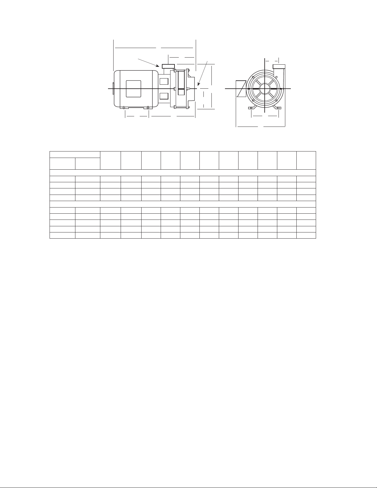
DIMENSIONS in INCHES
J
2” Discharge
F
3” Suction
E
D
K
A C
Figure 1
C22000 SERIES
Catalog Number
1 Phase 3 Phase
C22131 — 3 182JM 4.50 7.50 10.24 4.50 10.81 4.06 12.12 19.49 3.44
— C22133 3 145JM 5.00 5.50 9.49 3.50 9.81 4.06 10.50 17.87 3.44
C22151 — 5 184JM 5.50 7.50 10.24 4.50 10.81 4.06 12.12 20.49 3.44
— C22153 5 182JM 4.50 7.50 10.24 4.50 10.81 4.06 12.12 20.49 3.44
C22231 — 3 182JM 4.50 7.50 12.49 4.50 10.81 6.31 12.12 20.49 3.44
— C22233 3 145JM 5.00 5.50 11. 74 3.50 9.81 6.31 10.50 20.12 3.44
C22251 — 5 184JM 5.50 7.50 12.49 4.50 10.81 6.31 12.12 22.74 3.44
— C22253 5 182JM 4.50 7.50 12.49 4.50 10.81 6.31 12.12 22.74 3.44
— C22273 7-1/2 184JM 5.50 7.50 12.49 4.50 10.81 6.31 12.12 22.74 3.44
Dimensions shown above are approximate maximum dimensions for standard pumps equipped with open drip
proof motors.
HP
Motor
Frame
Size
A B C D E F G J K
SINGLE STAGE 3500 RPM
TWO STAGE 3500 RPM
If a dry location is not available mount it on a
foundation well above the wet floor.
WARNING: Do not handle the pump with wet hands or
when standing in water as fatal electrical shock could
occur. Disconnect main power before handling unit
for ANY REASON!
Pumps incorporate a discharge port on the pump
3.
casing that can be adjusted in 90° increments. If
necessary adjust the discharge port to accommodate
the specific application. Pump performance will not
be affected by the position of the discharge port.
SUCTION LIMITATIONS
1. Units are non self-priming. Normally after being
primed the total suction lift of the pump is 15 feet.
2. Where liquids at or near their boiling points are
being handled, the supply must be located above
the suction, so that the available NPSH will be
greater than that required by the unit.
PIPING
1. Do not use the pump as support to the piping. The
pipe must be independently supported near the
pump so that no strains will be transmitted to the
unit. Failure to do so will cause premature pump
failure and will void the warranty.
2. Suction and discharge sizes are selected for proper
performance of the pumping unit and are not
95 North Oak Street • Kendallville, IN 46755
Copyright 2011. All Rights Reserved.
B
G
IL1000
intended to determine the suction and discharge
pipe sizes. Pipe sizes must be determined by the
user based on the system requirements.
3. Install both a union and a gate valve (not furnished)
on the suction and discharge side of the pump for
service convenience.
CAUTION: Do not use a globe or other restricting
type of valve at the discharge. Globe valves seriously
restrict the capacity of the pump.
All joints and connections should have pipe sealing
4.
compound (male threads only) applied and drawn
up tightly.
CAUTION: The entire system must be air and water
tight for efficient operation.
SUCTION PIPING
1. Suction piping should be short in length, as direct
as possible, and never smaller in diameter than the
pump suction opening.
2. Use galvanized piping, rigid plastic or other suitable
pipe that will not collapse under suction.
3. The suction pipe should slope upward to the pump
inlet. A horizontal suction line must have a gradual
rise to the pump. Any high point in the pipe will
become filled with air and thus prevent proper
operation of the pump. When reducing the piping
to the suction opening diameter use an eccentric
2
Page 3

reducer with the eccentric side down to avoid air
IL1001
pockets. Never use a straight taper reducer in a
horizontal suction line, as it tends to form an air
pocket in the top of the reducer and the pipe.
Valves in Suction Piping
1. If the pump is operating under static suction lift
conditions, a foot valve may be installed in the
suction line to avoid the necessity of priming each
time the pump is started.
2. When foot valves are used, or where there are other
possibilities of “liquid hammer”, close the discharge
valve before shutting down the pump.
3. The pump must never be throttled by the use of
a valve on the suction side of the pump. Valves
should be used only to isolate the pump for
maintenance purposes, and should always be
installed in positions to avoid air pockets.
DISCHARGE PIPING
1. On long horizontal runs it is desirable to maintain as
even a grade as possible. Avoid high spots, such as
loops, which will collect air and throttle the system
or lead to erratic pumping.
Valves In Discharge Piping
1. A check valve and gate valve should be installed
in the discharge. The check valve, placed between
the pump and the gate valve, protects the pump
from excessive pressure, and prevents liquid from
running back through the pump in case of power
failure. The gate valve is used in priming and
starting, and when shutting the pump down.
Pressure Gauges
1. Properly sized pressure gauges can be installed
in both the suction and discharge openings in the
gauge taps which are provided. The gauges will
enable the operator to easily observe the operation
of the pump, and also determine if the pump is
operating in conformance with the performance
curve. If cavitation, vapor binding or other unstable
operation should occur, widely fluctuating discharge
pressure will be noted.
ELECTRICAL CONNECTIONS
GROUNDING
1. To reduce the risk of electric shock. The motor must
be securely and adequately grounded to a grounded
metal raceway system or by using a separate
grounding wire connected to bare metal on the
motor frame, or to the grounding screw located
inside motor terminal box, or other suitable means.
Refer to National Electric Code (NEC Article 250
[Grounding]) for additional information.
2. All wiring should be preformed by a qualified
electrician and in accordance with the National
Electric Code, Local Electric Codes and the
Occupational Safety and Health Act (OSHA).
WARNING: Failure to connect the motor frame to
equipment grounding conductor by using green screw
may result in serious electrical shock.
95 North Oak Street • Kendallville, IN 46755
Copyright 2011. All Rights Reserved.
WIRING CONNECTIONS
1. This unit is not water proof and is not intended to
be used in showers, saunas, or other potentially
wet locations. The motor is designed to be used
in a clean dry location with access to an adequate
supply of cooling air. Ambient temperature around
the motor should not exceed 104°F (40°C). For
outdoor installations motor must be protected by a
cover that does not block airflow to and around the
motor. This unit is not weatherproof nor is it able to
be submersed in water, or any other liquid.
2. Motor voltages will vary depending upon the motor
horsepower, phase and manufacturer. Refer to the
motor nameplate for voltage and electrical data.
WARNING: Make certain that the power supply
conforms to the electrical specifications of the motor
supplies. Failure to do so may cause premature motor
failure and will void the warranty.
3. For proper electrical connections, refer to the
connection diagram located on the nameplate
or inside the terminal box of the motor. Make
sure connections are correct for the voltage being
supplied to the motor.
4. Whenever possible, the pump should be powered
from a separate branch circuit of adequate capacity
to keep voltage drop to a minimum during starting
and running. For longer runs, increase wire size
in accordance with the Wire Selection Guide. (See
Figures 3 & 4)
Suction Pipe Installed
Increaser
Gate Valve
Check Valve
Figure 2
With Gradual Rise To
Pump Inlet
Pipe
Support
Eccentric
Reducer
Center Line
of Pipe
Level
NOTE: Wire charts are for reference only. Consult
local and state codes for approved wire sizes.
WARNING: Always disconnect power source before
performing any work on or near the motor or its
power source. Failure to do so could result in
personal injury or fatal electrical shock.
3
Page 4
SINGLE PHASE
IL0102
Distance From Motor
To Fuse Box Meter,
or Electrical Outlet
100 ft.
150 ft.
200 ft.
300 ft.
500 ft.
11 5 V
230V
11 5 V
230V
11 5 V
230V
11 5 V
230V
11 5 V
230V
Recommended Copper Wire Size
1HP 1-1/2 HP 2 HP 3 HP 5 HP
10
14
6
12
6
12
*
12
*
10
12
12
10
8
6
6
*
6
*
4
10
10
8
*
8
4
*
8 4
4
*
8
6
*
*
6
4
*
*
4
2
(*) Not economical to run at 115V, use 230V.
Figure 3
THREE PHASE
Distance From
Motor To Fuse
Box Meter, or
Electrical Outlet
100 ft.
150 ft.
200 ft.
300 ft.
500 ft.
230V
460V14141212121212121012812
230V
460V1414121212121012812612
230V
460V1414121212121012812612
230V
460V121412121012812610
230V
460V10141012812610
Recommended Copper Wire Size
1-1/2
1HP
2 HP 3 HP 5 HP
HP
7-1/2
HP
4
10
4
2
8
8
Figure 4
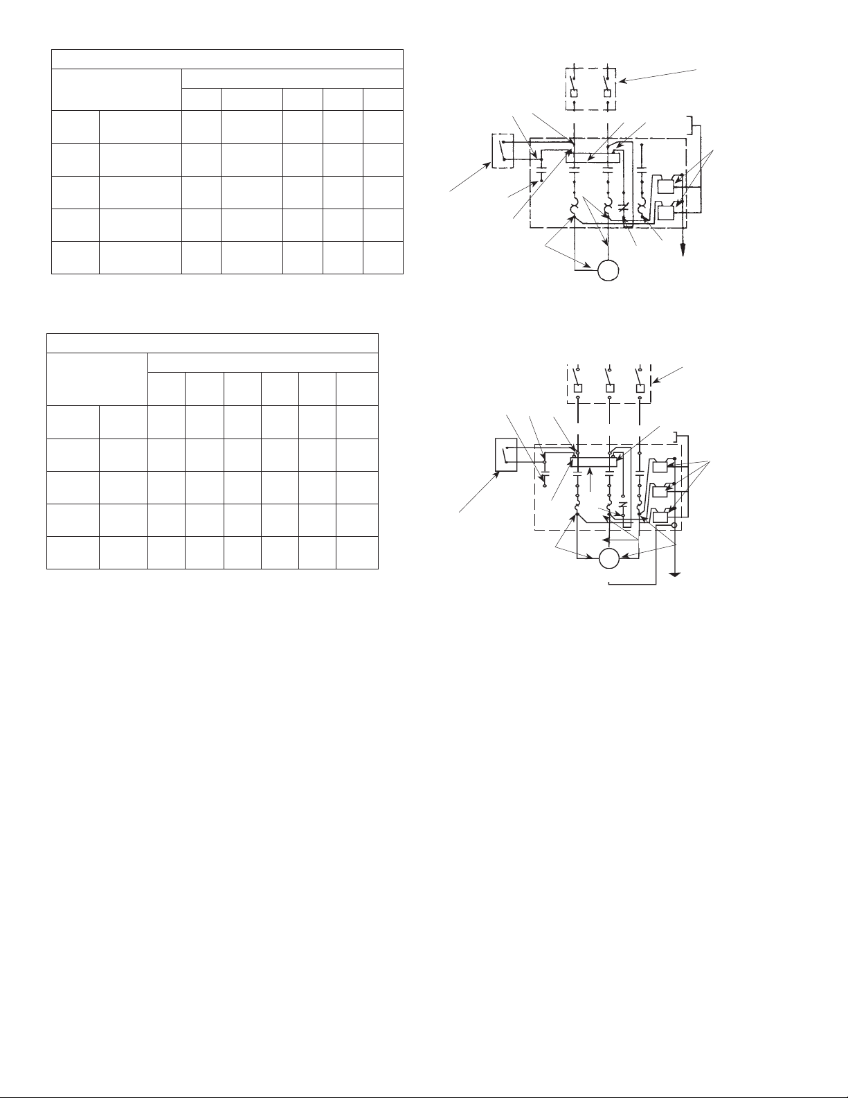
MOTOR PROTECTION
WARNING: Never examine, make wiring changes
or touch the motor before disconnecting the main
electrical supply switch.
Motors may or may not have built-in thermal
1.
overload protection depending upon the
horsepower size, phase, type and motor
manufacturer. Refer to the motor nameplate for
overload protection information. It is recommended
that a properly sized magnetic or manual starter
(both with properly sized heaters) be used with all
motors. Install starters following instructions of the
starter manufacturer. See Figure 5 & 6 for magnetic
starter wiring diagram.
2. All motors (single and three phase) should be
equipped with a correctly fused disconnect switch
to provide protection. Consult Local or National
Electrical Codes for proper fuse protection based on
motor nameplate.
3. Undersize wiring can cause motor failure (low
voltage), frequent cut-out of motor overload
protector, television interference and even fire.
Make certain the wiring is adequately sized (Figure
3 & 4), well insulated and connected to a separate
circuit outside the building in case of fire.
95 North Oak Street • Kendallville, IN 46755
Copyright 2011. All Rights Reserved.
Magnetic Starter Wiring
Diagram - Single Phase
1
-
3
L1
L2
W
M
6
-
4
-
Pressure
Switch
2
V
T2
Fused
Disconnect
Switch
Lightning
Arrestors
2
-
0
Warning: Connect
motor leads
momentarily for
correct rotation
T1
#10 Or Heavier Copper Ground Wire,
Connect To 8 ft. Ground Rod Or Well Casing
X2
Motor
T3
Figure 5
2
Pressure Switch
Magnetic Starter Wiring
Diagram - Three Phase
3
1
L1
L2
M
V
X2
T1
T2
Motor
#10 Or Heavier Copper Ground Wire,
Connect To 8 ft. Ground Rod Or Well Casing
L3
T2
Fused Disconnect
Switch
W
Lightning
Arrestors
T3
Figure 6
OPERATION
PRIOR TO STARTING
1. Before the pump is started initially, make the
following inspections:
• Check Rotation - Be sure that the pump operates in
the direction indicated by the arrow on the pump
casing, as serious damage can result if the pump
is operated with incorrect rotation. Rotation is
always counterclockwise facing the pump suction.
Operating the pump in reverse rotation may cause
extensive damage.
• Check all connections to motor and starting device
with wiring diagram. Check voltage, phase and
frequency on motor nameplate with line circuit.
ALL PUMPS WITH 3 PHASE MOTORS MUST BE
INSTALLED WITH A MAGNETIC STARTER WHICH
PROVIDES 3-LEG PROTECTION FOR MOTOR.
FAILURE TO USE CORRECT STARTER WILL VOID THE
WARRANTY.
PRIMING
1. Before starting any centrifugal pump it is absolutely
necessary that both the casing and suction pipe be
4
Page 5

completely filled with liquid. This priming can be
accomplished by any of the following methods.
2. When the liquid supply level is above the center
line of the pump, it is primed by opening the
suction and discharge valves. The inflowing liquid
will displace the air and fill the suction line, pump
casing, and discharge line up to the level of supply.
3. Where the pump is operating with suction lift and
the suction line is equipped with a foot valve, the
system is filled with liquid by filling through the
discharge piping.
STARTING
1. Follow the steps below in the order indicated to start
pump:
• Close gate valve in discharge line.
• Open gate valve in suction line.
• Turn on power to pump motor.
2. When pump is operating at full speed, immediately
open the discharge gate valve slowly.
3. If the pump does not prime properly, or loses it
prime during start-up it should be shut-down and
the condition corrected before the procedure is
repeated.
NOTE: The gate valve in the discharge line should
always be closed when the pumps is started. The
excessive current required by the motor to start under
full load will in time cause motor trouble. A centrifugal
pump primed and operated at full speed with the
discharge gate valve closed usually requires much less
power than when it is operating at its rated capacity
and head with the discharge gate valve open.
OPERATING CHECKS
1. After initial start-up:
• Check the pump and piping to assure there are no
leaks.
• Check and record pressure gauge readings for
future reference.
• Check and record voltage, amperage per phase.
STOPPING PUMP
1. When stopping pump always close the discharge
valve first.
2. Pump should never run for any length of time with
both suction and discharge valves closed due to
danger of building up pressures and temperatures.
MAINTENANCE
LUBRICATION
1. The pump and motor requires no lubrication. The
ball bearings of the motor have been greased at the
factory. Under normal operating conditions they
should require no further greasing.
FREEZING
1. Drain the entire system if there is danger of freezing.
A drain plug is provided at the bottom of the pump
case for this purpose.
95 North Oak Street • Kendallville, IN 46755
Copyright 2011. All Rights Reserved.
ROTARY SHAFT SEAL
1. The mechanical shaft seal should be replaced if
water is noticed around the motor shaft. Remove
case and impeller and, using two screw drivers to
pry on each side, remove seal stationary seat. Clean
seat area of frame, install new stationary seat with
ceramic surface facing out and slide new rotating
element over shaft sleeve with hard carbon surface
against ceramic seat. Be sure to keep all surfaces
clean. Lubricating seal parts with water will help the
installation of the seal. Reinstall impeller and pump
case.
CAUTION: Make certain that the power supply is
disconnected before attempting to service the unit!
Failure to do so could result in personal injury or fatal
electrical shock.
MOTOR
1. Keep motor clean and dry. It is drip-proof when
installed horizontally and the windings are protected
from excess humidity, but extreme conditions
should be avoided when possible. If motor fails to
run, be sure power is on, all switches or electrical
controls are closed, fuses are in order and all
electrical connection are tight. (Motor must be
repaired by Authorized Repair Station under terms
of guarantee.)
FAILURE TO PUMP
1. If the motor runs, but no water is pumped, be
sure pump is primed, that there are no air leaks in
suction piping, that all gate valves are open and all
check valves operate.
NET POSITIVE SUCTION HEAD (NPSH)
1. NPSH combines all of the factors limiting the
suction side of a pump; internal pump losses,
static suction lift, friction losses, vapor pressure
and atmospheric conditions. It is important
to differentiate between REQUIRED NPSH and
AVAILABLE NPSH.
NPSH REQUIRED
1. REQUIRED NPSH is a factor designed into a pump
and measurable in the test laboratory by the
manufacturer. Testing facilities can determine losses
in the suction piping, static lift and barometric
pressures.
NPSH AVAILABLE
1. The term for providing sufficient pressure on the
suction, at the impeller eye, to prevent “boiling”
is known as NPSH AVAILABLE. It is a function of
the pumping system and consists of pressure on
the liquid at its source, the elevation of the liquid
with respect to the impeller centerline, losses in the
suction piping and vapor pressure of the liquid.
2. If the available NPSH is not equal to, or greater than
that required by the pump, it must be increased.
This is usually done by increasing the static head,
Hz.
5
Page 6

NPSH FORMULAS
PROPOSED INSTALLATION
1. To calculate the NPSH available in a proposed
application, the following formula is recommended:
Hsv = Hp ± Hz - Hf - Hvp
2. Hsv-Available NPSH expressed in feet of fluid
3. Hp-Absolute pressure on the surface of the liquid
where the pump tanks suction, expressed in feet.
This could be atmospheric pressure or vessel
pressure (pressurized tank).
4. Hz-Static elevation of the liquid above, or below the
centerline of the impeller, expressed in feet.
5. Hf-Friction and entrance head loss in the suction
piping, expressed in feet.
6. Hvp-Absolute vapor pressure of the fluid at the
pumping temperature, expressed in feet of fluid.
PROPERTIES OF WATER
Temperature
ºF
60 0.26 0.59 0.999
85 0.60 1.4 0.996
100 0.95 2.2 0.993
120 1.69 3.9 0.989
130 2.22 5.0 0.986
140 2.89 6.8 0.983
150 3.72 8.8 0.981
160 4.74 11. 2 0.977
170 5.99 14.2 0.974
180 7.51 1 7. 8 0.970
185 8.38 20.0 0.969
190 9.34 22.3 0.966
195 10.38 24.9 0.964
200 11.53 27.6 0.963
202 12.01 28.8 0.962
204 12.51 30.0 0.961
206 13.03 31.2 0.960
208 13.57 32.6 0.960
210 14.12 33.9 0.959
212 14.70 35.4 0.958
214 15.29 37.0 0.957
216 15.90 38.4 0.956
218 16.54 40.0 0.956
220 1 7. 1 9 41.6 0.955
222 17.86 43.3 0.954
224 18.56 45.0 0.953
226 19.28 46.8 0.953
228 20.02 48.6 0.952
230 20.78 50.5 0.951
240 24.97 61.0 0.947
250 29.83 73.2 0.943
300 67.00 168.6 0.918
350 134.60 349.0 0.891
Absolute Vapor
Pressure
PSI Ft. Water
Specific
Gravity
6
95 North Oak Street • Kendallville, IN 46755
Copyright 2011. All Rights Reserved.
Altitude
(Feet)
-1000 31.0 15.2 32.5 213.8
-500 30.5 15.0 34.6 212.9
0.0 29.9 14.7 33.9 212.0
+500 29.4 14.4 33.3 211.1
+1000 28.9 14.2 32.8 210.2
+1500 28.3 13.9 32.1 209.3
+2000 27.8 13.7 31.5 208.4
+2500 27.3 13.4 31.0 207.4
+3000 26.8 13.2 30.4 206.5
+3500 26.3 12.9 29.8 205.6
+4000 25.8 12.7 29.2 204.7
+4500 25.4 12.4 28.8 203.8
+5000 24.9 12.2 28.2 202.9
+5500 24.4 12.0 27.6 201.9
+6000 24.0 11. 8 27.2 201.0
+6500 23.5 11.5 26.7 200.1
+7000 23.1 11. 3 26.2 199.2
+7500 22.7 11.1 25.7 198.3
+8000 22.2 10.9 25.2 197.4
+8500 21.8 10.7 24.7 169.5
+9000 21.4 10.5 24.3 165.5
+9500 21.0 10.3 23.8 194.6
+10000 20.6 10.1 23.4 193.7
+15000 16.9 8.3 19.2 184.0
Barometer
Inches
Mercury
Atmospheric
Pressure
PSIA (ft. water)
Boiling
Point ºF
Page 7

Troubleshooting Chart
Symptom Possible Cause(s) Corrective Action
Low or no discharge 1. Incorrect rotation 1. Refer to wiring diagram
2. Insufficient inlet pressure or suction head
(NPSH Required)
3. Total head too high 3. Lower discharge head
4. Leak in suction line 4. Repair or replace
5. Impeller clogged or damaged 5. Clean or replace
6. Wrong size piping 6. Make needed adjustments
7. Casing gasket leaking 7. Replace gasket
8. Suction or discharge line valves closed 8. Open
9. Mechanical seal leaking 9. Replace
Loss of suction 1. Insufficient inlet ressure or suction head
(NPSH Required)
2. Clogged strainer 2. Clean or replace
2. Increase inlet pressure by adding more fluid to fluid
source. (See Spec’s for minimum NPSH Required)
1. Increase inlet pressure by adding more fluid to fluid
source. (See Spec’s for minimum NPSH Required)
Pump vibrates and/or
makes excessive noise
Pump leaks at shaft 1. Damaged or worn mechanical seal 1. Replace
Pump will not start or
run
Motor problems 1. Various 1. Consult qualified electrician
Pinholes in the casting.
Liquid dripsp around
seal area but is not seal
1. Mounting plate or foundation not rigid
enough
2. Foreign material in pump 2. Clean
3. Damaged impeller 3. Replace
4. Cavitation present 4. Check suction line for proper size and be sure valve is
2. Corrosion due to character of liquid
pumped
1. Improperly wired 1. Refer to wiring diagram
2. Blown fuse or open circuit breaker 2. Replace fuse or close circuit breaker
3. Loose or broken wiring 3. Tighten connections and replace broken wiring
4. Impeller clogged 4. Clean
5. Motor shorted out 5. Replace
2. Overloading motor. Too much water
delivery
3. Liquid heavier and more viscous than
water
4. Seal binding 4. Replace
5. Rotor binding 5. Repair or replace
6. Voltage and frequency lower than rating 6. Reconnect to rated voltage and frequency
7. Defects in motor 7. Repair or replace
1. Cavitation caused by insufficient
inlet pressure or suction head (NPSH
Required)
1. Reinforce
open. Remove excessive loops in suction line. (See Spec’s
for minimum NPSH Required)
2. Discontinue pumping liquid and consult factory
2. Restrict outlet by closing down valve in discharge line
3. Consult factory
1. Increase inlet pressure by adding a higher level of fluid
to source or increasing inlet pressure. (See Spec’s for
minimum NPSH Required)
95 North Oak Street • Kendallville, IN 46755
Copyright 2011. All Rights Reserved.
7
Page 8

CENTRIFUGAL PUMP REPAIR PARTS
“C22000” SERIES
(For Pricing Refer To Repair Parts Price List)
1
15
2
3
8
4
9
PAGE 4-5A REPAIR PARTS
10
11
13
FORM NO. FW0043
SUPERSEDES 1007
8
0309
14
Qty.
021434 Repair Kit
Kit Includes:
Item
Part No. & Description
No.
Two Stage
2
1
4
3
12
5
8
6
1 3 136559 Seal Assembly
1
•
1
1
2
136576 O-Ring, Cap Screw
•
136572 O-Ring, Impeller
•
136569 O-Ring, Impeller
8
124638 Gasket
15
Single Stage
7
IL0200
Product may not be exactly as shown.
ITEM HORSEPOWER 3 5 3 5 7-1/2
STAGE 1 1 2 2 2
SINGLE PHASE C22131 C22151 C22231 C22251 —
THREE PHASE C22133 C22153 C22233 C22253 C22273
DESCRIPTION PART NUMBER
1
Motor — 1 Phase
1
Motor — 3 Phase
2
Mounting Ring
3
Seal Assembly
•
Key 3/16 x 27/32”
•
Key 3/16 x 2-1/32”
4
Impeller
•
O-Ring, Impeller
5
Retainer, Impeller
6
Cap Screw 1” Long
•
O-Ring, Cap Screw
7
Lock Washer 3/8” S.S.
8
Gasket
9
Intermediate Stage w/Clearance Ring
•
Clearance Ring - Large
•
Clearance Ring - Small
10
Impeller (Front)
11
Retainer, Impeller
•
O-Ring, Impeller
12
Cap Screws 2-1/4” Long
•
O-Ring, Cap Screw
13
Lock Washer 3/8” S.S.
14
Suction Flange Assembly w/Clearance Ring
•
Clearance Ring
•
Pipe Plug 1/4” NPT
15
Hex Hd. Cap Screws 3/8 x 1”
16
Hex Hd. Cap Screws 3/8 x 1-1/4”
17
(*) Standard hardware item
(•) Notshown
Hex Hd. Cap Screws 3/8 x 3-1/4”
134962
134965
136556
136559
136560
—
136561
136569
136570
136573
136576
120649
124638 (1)
—
—
—
—
—
—
—
—
—
023089
125176
* (4)
* (4)
* (6)
—
124638 (1)
8
134963
134966
136556
136559
136560
—
136562
136569
136570
136573
136576
120649
—
—
—
—
—
—
—
—
—
023089
125176
* (4)
* (4)
* (6)
—
134962
134965
136556
136559
—
134977
136563
136569
—
—
—
—
124638 (2)
136578
125176
136577
136564
136571
136572
136575
136576
120649
023089
125176
* (5)
* (4)
—
* (6)
134963
134966
136556
136559
—
134977
136565
136569
—
—
—
—
124638 (2)
136578
125176
136577
136566
136571
136572
136575
136576
120649
023089
125176
* (5)
* (4)
—
* (6)
95 North Oak Street • Kendallville, IN 46755
Copyright 2011. All Rights Reserved.
17
14
16
—
134967
136556
136559
—
134977
136567
136569
—
—
—
—
124638 (2)
136578
125176
136577
136568
136571
136572
136575
136576
120649
023089
125176
* (5)
* (4)
—
* (6)
 Loading...