

Page 1

Operating Instructions & Parts Manual
Please read and save these instructions. Read carefully before attempting to assemble, install, operate or maintain the product
described. Protect yourself and others by observing all safety information. Failure to comply with instructions could result in personal injury and/or property damage! Retain instructions for future reference.
Booster Pump Flow Protector
FW1023
1106
Supersedes
NEW
Control Box
115V SPECIFICATIONS
Enclosure . . . . . . . . . . . . . . . . . . . . NEMA 1 Indoor Use Only
Voltage . . . . . . . . . . . . . . . . . . . . . . . . . . . . . . . . . . . . . . . 115
Maximum HP Rating . . . . . . . . . . . . . . . . . . . . . . . . . . . . .3/4
Phase . . . . . . . . . . . . . . . . . . . . . . . . . . . . . . . . . . . . . . . . . . . 1
Hertz . . . . . . . . . . . . . . . . . . . . . . . . . . . . . . . . . . . . . . . .50/60
Contact Rating . . . . . . . . . . . . . . . . . . . 15 Amps @ 115/Volts
Flow Sensor
Contact Rating . . . . . . . . . . . . . . . . . . . . . . . . . . . .Max 20VA
Min. Flow for Contat Closure . . . . . . . . . . . . . . . . . . .1 GPM
Pressure Rating . . . . . . . . . . . . . . . . . . . . . . . . Max. 150 PSIG
Temperature Rating . . . . . . . . . . . . . . . . . . . . . . 32 to 140˚ F
Inlet and Outlet . . . . . . . . . . . . . . . . . . . . . . . . . . 1” Slip PVC
General Safety Information
Carefully read and follow all safety instructions in this
manual and on pump. Keep safety labels in good condition.
Replace missing or damaged safety labels.
This is a SAFETY ALERT SYMBOL. When you
see this symbol on the pump or in the manual,
look for one of the following signal words and
be alert to the potential for personal injury or
property damage.
Warns of hazards that WILL cause serious
personal injury, death or major property damage if ignored.
!
personal injury or death, if ignored.
Warns of hazards that CAN cause serious
Control Box
230V SPECIFICATIONS
Enclosure . . . . . . . . . . . . . . . . . . . . NEMA 1 Indoor Use Only
Voltage . . . . . . . . . . . . . . . . . . . . . . . . . . . . . . . . . . . . . . . 230
Maximum HP Rating . . . . . . . . . . . . . . . . . . . . . . . . . . . . . . 2
Phase . . . . . . . . . . . . . . . . . . . . . . . . . . . . . . . . . . . . . . . . . . . 1
Hertz . . . . . . . . . . . . . . . . . . . . . . . . . . . . . . . . . . . . . . . .50/60
Contact Rating . . . . . . . . . . . . . . . . . . . 20 Amps @ 230/Volts
Flow Sensor
Contact Rating . . . . . . . . . . . . . . . . . . . . . . . . . . . .Max 20VA
Min. Flow for Contat Closure . . . . . . . . . . . . . . . . . . .1 GPM
Pressure Rating . . . . . . . . . . . . . . . . . . . . . . . . Max. 150 PSIG
Temperature Rating . . . . . . . . . . . . . . . . . . . . . . 32 to 140˚ F
Inlet and Outlet . . . . . . . . . . . . . . . . . . . . . . . . . . 1” Slip PVC
!
Hazardous
voltage. Can
shock, burn or
cause death.
Ground pump
before connecting
to power supply.
Verify motor is wired for correct
voltage. See motor wiring diagram provided
by the pump or motor manufacturer.
Ground motor before connecting to
power supply.
Meet United States National Electrical
Code and local codes for all wiring.
Do not handle a pump, pump motor
or control unit with wet hands or when
standing on a wet or damp surface or in
water.
Warns of hazards that MAY cause minor
personal injury, product or property damage if ignored.
IMPORTANT: Indicates factors concerned with operation,
installation, assembly or maintenance which could result in
damage to the machine or equipment if ignored.
NOTE: Indicates special instructions which are important but
are not related to hazards.
FLINT & WALLING, INC. • 95 North Oak St. • Kendallville, IN 46755 • www.flintandwalling.com
Follow wiring instructions in this manual when
connecting to power lines.
!
performing any work on or near the motor or its connected
load.
1
Always disconnect power source before
022354
Page 2
Do not use to pump flammable or explosive
fluids such as gasoline, fuel oil, kerosene,
etc. Do not use in flammable and/or explosive
atmospheres.
Hazardous pressure! Install pressure relief
valve in discharge pipe. Release all pressure on
system before working on any component.
1. Make workshop child proof - use padlocks, master
switches; remove starter keys.
2. Wear safety glasses when working with pumps.
3. Wear a face shield and proper apparel when pumping
hazardous chemicals.
4. Keep work area clean, uncluttered and properly lighted;
replace all unused tools and equipment.
5. Provide guarding around moving parts.
6. Keep visitors at a safe distance from the work area.
7. Periodically inspect pump and system components.
8. Protect electrical cord. Replace or repair damaged or
worn cords immediately.
9. Do not insert finger or any object into pump or motor
openings.
!
to the State of California to cause cancer and birth defects or
other reproductive harm.
!
not been investigated for use in swimming pool areas.
This product contains chemicals known
Risk of Electric Shock. This controller has
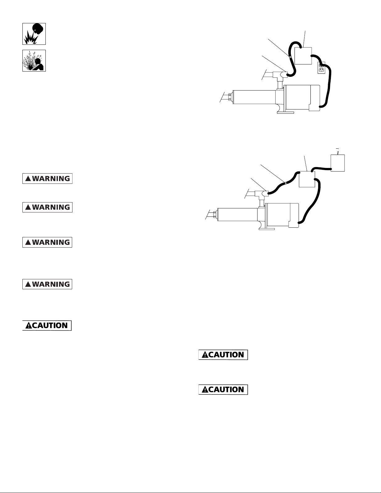
OUTLET
Figure 1
OUTLET
CONNECTORS
FLOW
SENSOR
INLET
115 VOLT INSTALLATION
CONNECTORS
FLOW
SENSOR
INLET
ELECTRONIC CONTROL
F&W
ELECTRONIC CONTROL
F&W
PAT.
PEND
IL0631
115 VOLT
CONTROLLER #2
FUSE DISCONNECT OR
BOOSTER
BREAKER BOX
230 VOLT
LOCATION
!
damage and/or personal injury might result from an
inoperative or leaking pump due to power outages,
discharge line blockage, or any other reason, a backup
system(s) should be used.
!
installation where pump pressure can exceed the plumbing’s
maximum working pressure or on systems where the
discharge line can be shut off or obstructed. Extreme over
pressure can result in personal injury or property damage.
intended to be used in showers, saunas or other potentially
wet locations. For outdoor installations, control unit must
be protected from the elements by a cover. This unit is not
weatherproof nor is it able to be submersed in water or any
other liquid.
In any installation where property
Install a pressure relief valve on any
This unit is not waterproof and is not
DESCRIPTION
For pressure boosting systems, the electronic flow sensorcontrol unit monitors the flow of water and automatically
shuts off the motor when the flow drops below 1.0 GPM.
Once the flow has increased above 1.0 GPM, the unit will
automatically turn the motor back on to boost the system
pressure. The device protects against dry run or dead head
conditions that are caused by a low yield water supply or
an obstructed water discharge. Note: This electronic flow
protection system is designed to be used with a positive
supply of water feeding the pump.
NOTE: The unit will not function if the pump is used in a
suction lift application.
230 VOLT INSTALLATION
IL0629
Figure 2
INSTALLATION
1. Electronic flow protector box should be located within six
feet of the pump motor and power supply and should be
mounted to a solid surface.
Note: Follow all recommended installation procedure for
pump as provided by pump manufacture.
2. Plumb flow sensor on into the inlet side of the pump,
making sure that your water supply line is feeding the
inlet port of the flows sensor and the outlet port of the
flow sensor is plumbed to the inlet port of the pump (See
Figures 1 & 2). Use standard medium bodied PVC solvent
cement to attach piping to flow switch.
Care should be taken to use the minimum
recommended amount of PVC cement to insure that no
excess cement enters into the sensor of the unit and causes a
malfunction which can void the warranty.
If dirt, sand, debris or other particulate is
present in the supply water, install a strainer or filter on the
inlet side of the flow sensor to insure proper operation of
sensor and pump.
3. Plug the two red wires from the electronic flow protector
box into the two red wires on the flow sensor.
2
FLINT & WALLING, INC. • 95 North Oak St. • Kendallville, IN 46755 • www.flintandwalling.com
Page 3

WIRING PROCEDURES FOR 115V CONTROL
Make certain that the power supply
conforms to the electrical specifications of the motor
supplied. If the motor wiring must be changed to conform to
your specific voltage requirements, consult documentation
provided with the pump motor for correct procedure.
1. Install and maintain your pump in accordance with your
local electrical code and all other codes and ordinances
that apply. Consult your local building inspector for local
code information.
2. Plug the 115V power cord from the electronic flow
protector box into a properly grounded 115V receptacle.
3. Plug a properly sized and grounded power cord from the
pump motor into the “piggy back” outlet of the power
cord of the electronic flow protector.
IMPORTANT: Check local and/or United States National
Electric Codes for proper grounding information.
6. Connected black and white wires as specified by local or
United States National Electrical code to the disconnected
supply voltage.
230 VOLT INSTALLATION
FLOW SENSOR
PRESSURE
RELIEF VALVE
TO DRAIN
Figure 4
CONNECTORS
PRESSURE GAUGE
LINE FILTER
230 VOLT
ELECTRONIC FLOW PROTECTOR
F&W
GATE/BALL VALVE
FROM
WATER SOURCE
GATE/BALL VALVE
(NORMALLY OPEN)
FUSE DISCONNECT OR BREAKER BOX
IL0628
115 VOLT INSTALLATION
ELECTRONIC FLOW PROTECTOR
CONNECTORS
WALL HYDRANT
HIGH PRESSURE
REINFORCED HOSE
HOSE
ADAPTER
FLOW
SENSOR
Figure 3
WIRING PROCEDURES FOR 230V CONTROL
Make certain that the power supply
conforms to the electrical specifications of the motor
supplied. If the motor wiring must be changed to conform to
your specific voltage requirements, consult documentation
provided with the pump motor for correct procedure.
1. Feed the lead wire labeled Output (Motor) from the
electronic flow protector to the terminal block of the
motor.
2. Connect the green ground wire first to the grounding
terminal provided on the motor frame. Ground connection
MUST be made to this terminal. Do not connect motor to
electrical power supply until unit is permanently grounded;
otherwise serious or fatal electric shock hazard may be
caused.
3. Attach the black and white wires to the power
supply terminals or wires of the pump motor, consult
documentation provided with the pump motor for correct
location and wiring procedures.
4. Feed the lead wire labeled Input Power from the electronic
flow protector to your 230V electrical power supply.
5. Connect the green ground wire first to the grounding
terminal within the electrical supply box as specified by
local or United States National Electrical code. Do not
ground to a gas supply line. Do not connect the electronic
flow protector to electrical power supply until unit is
permanently grounded; otherwise serious or fatal electric
shock hazard may be caused.
FLINT & WALLING, INC. • 95 North Oak St. • Kendallville, IN 46755 • www.flintandwalling.com
INLET
SPRAY
NOZZLE
F&W
115 VOLT
PRESSURE RELIEF
VALV E
OUTLET
HOSE ADAPTER
TO DRAIN
HIGH PRESSURE
REINFORCED HOSE
IL0630
OPERATION:
Priming of the pump is automatic when pump is connected to
a positive supply of water such as a hydrant or city main.
1. Disconnect power to the electronic flow protector and
pump. (Unplug 115V model, turn off disconnect to 230V
model.)
2. Open values and/or nozzle on suction and discharge side of
the pump.
3. To relieve trapped air, allow water supply to run a
minimum of 30 seconds before starting the pump.
4. Connect power to the electronic flow protector and pump.
(Plug in the 115V model, turn on disconnect to 230V
model.)
5. As long as there is at least 1.0 GPM of water flowing
through the pump, the pump will continue to run. If the
water supply or discharge valve and/or nozzle is closed,
which causes less that 1.0 GPM of water to flow through
the pump, the electronic flow protector will turn off the
pump in 20 to 30 seconds. Once the flow has returned to
at least 1.0 GPM, the flow protector will turn the pump
back on.
3
Page 4

Troubleshooting Chart / Booster Systems
Symptom Possible Cause(s) Corrective Action
Pump won’t
start or run
at full speed
Pump fails
to continue
to run
Pump
operates,
but delivers
little
or no water
1. Blown fuse or open circuit breaker 1. Replace fuse or close circuit breaker. See wire size chart for
proper break/fuse size
2. Power supply in OFF position 2. Turn power on
3. Incorrect voltage at motor (check
voltage with motor running)
4. Loose, broken or incorrect wiring 4. Rewire any incorrect circuits. Tighten connections, replace
5. Defective motor 5. Replace motor
6. Pump hydraulic components clogged/
worn/damaged or seized
7. Flow sensor installed incorrectly 7. Plumb flow sensor correctly with water supply entering inlet
8. There is no positive supply of water to
the pump.
1. Manual or solenoid valves plumbed
into system restricting flow
2. In-line filter restricting flow 2. Check all in-line filters to be sure they are not plugged or
3. Low line voltage 3. See low line voltage corrective action (above)
4. Inadequate water supply to booster
pump
3. Low voltage
a. Voltage must be within ± 10% of motor rated voltage.
Check incoming voltage. Contact power company
b. Make certain that voltage of motor matches voltage of
power supply. See motor name plate and motor wiring
diagrams
c. Check wire size from main switch to pump. See wire size
chart for correct wire size
defective wires
6. Replace worn parts or entire pump. Clean parts if required
side of the flow sensor and the outlet side plumbed to the
pump inlet.
8. Provide a positive supply of water to the pump.
1. a Check all valves on pump inlet and discharge sides of
system to be sure they are opened properly to allow
flow to and from the pump
b. Bleed trapped air in pump which keeps water from
reaching the pump. (Normally
due to closed valve in discharge plumbing)
restricted
4. Check pressure on inlet side of booster to be sure positive
pressure is maintained to the booster pump
5. Undersized piping 5. Replace undersized piping
6. Worn or defective pump parts or pump. 8. Replace worn parts or entire plugged impeller Clean parts if
7. Suction lift too great 9. Pump should be operated under
flooded suction only
8. Pump not primed 10. Prime pump - Make certain inlet pipe is drawn up tight and
pump and pipe are full of water
Excessive
noise while
pump in
operation
Pump leaks 1. Worn mechanical seal (leaks at shaft) 1. Replace shaft (rotary) seal
1. Pump not secured to firm foundation 1. Secure properly
2. Piping not supported 2. Make necessary adjustments
3. Restricted inlet line 3. Clean or correct
4. Cavitation (noise like marbles in pump) 4. Increase inlet pipe size back to source
5. Worn motor bearings 5. Replace bearings or motor
2. Worn o-ring seals 2. Replace o-ring seals, located inside both ends of the stainless
steel shell
4
FLINT & WALLING, INC. • 95 North Oak St. • Kendallville, IN 46755 • www.flintandwalling.com
 Loading...