

Page 1
Operating Instructions & Parts Manual
!
!
!
!
!
!
!
Please read and save these instructions. Read carefully before attempting to assemble, install, operate or maintain the product
described. Protect yourself and others by observing all safety information. Failure to comply with instructions could result in personal
injury and/or property damage! Retain instructions for future reference.
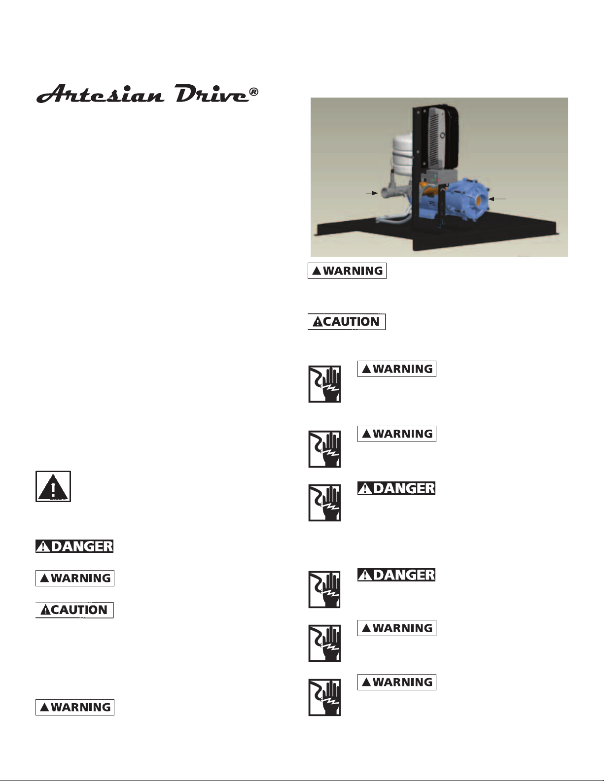
Pump Station
Models ADW2W31, ADW2W51,
ADW2W71, ADW2W73
Discharge
KEY FEATURES OF THE ARTESIAN DRIVE PUMP STATION
INCLUDE:
• Constant water pressure with a wide range of settings
(30-80 psi) (Note: The maximum obtainable system
pressure is limited by the performance of the pump
installed)
• Smaller pressure tank can be used
• No in-rush (power-on transient) current
• Low motor start-up current (soft-starting)
• Active Power Factor Correction minimizes input RMS
current
• Protection features
- Dry run conditions – using intelligent load monitoring
(see Page 6)
- High voltage / lightning surge
- Low line voltage
- Short circuit
General Safety Information
Carefully read and follow all safety instructions in
this manual and on pump. Keep safety labels in good
condition. Replace missing or damaged safety labels.
Manifold
Figure 1
controller can still hold a lethal voltage even after power
has been removed. Allow 10 minutes for dangerous internal
voltage to discharge before opening the unit.
capacitors with the Artesian Drive. Damage will result to both
motor and drive.
perform installation.
Capacitors inside the Artesian Drive
Do not use power factor correction
Electrical installations
shall be in accordance with National Electric
Code (NEC) and all applicable local codes
and ordinances. A licensed electrician should
Be sure system is connected
to a circuit equipped with a fuse or circuit
breaker of the correct rating.
Pump Intake
FW1365
0411
Supersedes
0610
this symbol on the pump or in the manual, look for one of
the following signal words and be alert to the potential for
personal injury or property damage.
personal injury, death or major property damage if ignored.
personal injury or death, if ignored.
personal injury, product or property damage if ignored.
IMPORTANT: Indicates factors concerned with operation,
installation, assembly or maintenance which could result in
damage to the machine or equipment if ignored.
NOTE: Indicates special instructions which are important but
are not related to hazards.
carefully. Failure to follow could result in serious bodily injury
and/or property damage.
This is a SAFETY ALERT SYMBOL. When you see
Warns of hazards that WILL cause serious
Warns of hazards that CAN cause serious
Warns of hazards that MAY cause minor
Read these warnings and instructions
95 North Oak St. • Kendallville, IN 46755 • 1-800-345-9422
Always disconnect power
source before performing any work on or near
the controller, motor or its connected load. If
the power disconnect point is out-of-sight, lock
it in the open position and/or tag it to prevent unexpected
application of power. Failure to do so could result in fatal
electrical shock or bodily injury.
DO NOT handle pump with wet
hands or when standing in water as fatal electrical
shock could occur. Disconnect main power supply
before handling system for any reason.
Protect the power cable from
coming in contact with sharp objects, oil, grease,
hot surfaces or chemicals. DO NOT kink the
power cable. If damaged replace immediately.
NEVER leave the control box,
fused disconnect switch, or covers open (either
partially or completely) when not being worked
on by a competent electrician or repairman.
1 (FW1365)
023423
Page 2
Always use caution when
!
!
!
!
!
!
!
!
!
operating electrical controls in damp areas. If possible,
avoid all contact with electrical equipment during
thunderstorms or extreme damp conditions.
Install all electrical equipment
in protected area to prevent mechanical damage
which could produce serious electrical shock and/
or equipment failure.
DO NOT use this system to pump
flammable liquids such as gasoline, fuel oil, kerosene,
etc. Failure to follow the above warning could result
in property damage and/or personal injury.
This product contains chemicals known
to the State of California to cause
cancer and birth defects or other reproductive harm.
Do not pump water above 140 degrees
Fahrenheit.
the drive until power has been removed and 10 minutes have
passed for internal voltages to discharge!
UNDERLOAD SENSITIVITY
The Artesian Drive controller is configured at the factory
to ensure detection of Underload faults in a wide variety
of pumping applications including dead head and run dry
conditions. In very rare cases (as with certain pumps in
shallow wells) this trip level may result in nuisance faults. If
the pump is installed in a shallow well, activate the controller
and observe system behavior. Once the controller begins to
regulate pressure, check operation at several flow rates to
make sure the default sensitivity does not induce nuisance
Underload trips. If it becomes necessary to desensitize the
Underload trip level, please call of Technical Support at 1-800345-9422 for further details.
Serious or fatal electrical shock may result
from contact with internal electrical components. DO NOT,
under any circumstances, attempt to modify connections to
the drive until power has been removed and 10 minutes have
passed for internal voltages to discharge!
This unit not tested for use
in swimming pool areas.
How it Works
SYSTEM DIAGNOSTICS
In addition to regulating system pressure and accurately
controlling motor operation, the Artesian Drive continuously
scans the system and can detect a variety of abnormal
conditions. If there is elevated risk of damage to a part of
the system, the drive will protect the system and display a
code for the fault. If possible, the drive will try to restart itself
when the fault condition passes.
PUMP SIZING – ARTESIAN DRIVE (CENTRIFUGAL)
The Artesian Drive is configured at the factory for use with
standard 3-phase motors and pumps.
NOTE: The Artesian Drives are factory programmed to
F&W pumps to provide optimum performance and motor
protection. The Artesian Drive can be used with other
pumps, but the maximum motor amperage needs to be
compared to the factory programmed current value (refer
to the Specifications section under the appropriate model).
If the maximum motor current varies more than 5% from
the programmed value, the motor current value in the drive
needs to be changed for motor protection and optimum
performance. For details on how to change this value in the
drive, please contact Technical Support at 1-800-345-9422.
event of a motor overload.
DRIVE CONFIGURATION
When sized correctly, the Artesian Drive systems are ready
to go right out of the box and need no configuration.
Under certain circumstances there are several programming
parameters that can be changed to accommodate non
standard systems. For further information to change these
parameters, please call Technical Support at 1-800-345-9422
from contact with internal electrical components. DO NOT,
under any circumstances, attempt to modify connections to
The motor rated current must be set
correctly to avoid a risk of fire in the
Serious or fatal electrical shock may result
Before Getting Started
from failure to connect the ground terminal to the motor,
Artesian Drive controller, metal plumbing, or other metal
near the motor or cable, using wire no smaller than motor
cable wires. To minimize risk of electrical shock, disconnect
power before working on or around the Artesian Drive
system. CAPACITORS INSIDE THE ARTESIAN DRIVE CONTROLLER
CAN STILL HOLD LETHAL VOLTAGE EVEN AFTER POWER HAS
BEEN DISCONNECTED. ALLOW 10 MINUTES FOR DANGEROUS
INTERNAL VOLTAGE TO DISCHARGE BEFORE REMOVING
ARTESIAN DRIVE COVER.
areas.
IMPORTANT: This equipment should be installed by technically
qualified personnel. Failure to install it in compliance
with national and local electrical codes and within F&W
recommendations may result in electrical shock hazard, fire
hazard, unsatisfactory performance, or equipment failure.
Installation information is available directly from F&W at our
toll-free number 1-800-345-9422.
three phase motors. Use of this unit with improperly sized
motors may result in damage to both motor and electronics.
Serious or fatal electrical shock may result
Do not use motor or system in swimming
Use Artesian Drive only with properly sized
Controller Location Selection
The drive’s enclosure is NEMA 1 rated
and is intended for indoor use only. It
should be mounted in a location that provides protection
from water spray/drips and only be accessed by trained and
authorized personnel.
The Artesian Drive controller is intended for operation in
ambient temperatures up to 104°F (40°C) at 230 VAC input.
Installation Guidance and Instructions
INITIAL CONDITIONS AND PRECAUTIONS
1. The Pump Station should be installed on flat surface rated
for the weight of the pump station. A properly sized
concrete slab is recommended.
2. Installation should be performed by licensed or qualified
personnel.
2 (FW1365)
95 North Oak St. • Kendallville, IN 46755 • 1-800-345-9422
Page 3
3. The Pump Station shall be lifted with proper lifting
!
!
!
!
!
equipment (i.e. fork lift). Be sure all necessary lifting
equipment is used properly.
4. DO NOT ATTEMPT TO USE DRIVE SUPPORT BRACKET FOR
LIFTING THE PUMP STATION. The bracket will not support
the overall weight of the pump station.
5. The pump station must be installed according NEC and
local electrical codes. Proper electrical disconnect MUST be
installed in view of the pump station.
6. Ensure compliance with all applicable local, state, and
OSHA regulations when installing, operating, repairing, or
maintaining the pump station.
7. The pump station is manufactured to best ensure operator
safety under normal operating conditions. The manufacturer
will not take any responsibility for personal or equipment
damage if the equipment has been modified or if the
safeguards have been modified. Any proposed modifications
must be carefully documented (to include a risk analysis) by
the party proposing the modification; and coordinated with
and approved by the manufacturer. Otherwise, the customer
assumes all responsibility for its actions and subsequent
consequences.
INSTALLATION PROCEDURE
1. Position the skid in final location and attach to pad as
necessary. NOTE: For serviceability of the pump and
protection of discharge plumbing fixtures down line of the
pump station, it is recommended to incorporate unions and
isolation valves on the intake and discharge plumbing. If
deemed applicable, a bi-pass loop with properly placed
valves should also be incorporated into the installation.
2. Install plumbing to the intake of the pump. Note: For
proper functionality of the system it is not recommended
that a pipe size smaller than 2-1/2” is use on the intake of
the pump. Note: For suction lift applications, intake pipe
plumbing needs to allow for suction pipe to be filled by
external water source to prime the pump. Note: If the water
source for the pump station is susceptible to containing
debris, an appropriately sized filter should be installed prior
to the pump intake which should be checked & cleaned
regularly to avoid clogging the pump and/or degrade system
performance.
3. Install plumbing to discharge manifold. Note: For proper
functionality of the system it is not recommended that a pipe
size smaller than 2” is use on the discharge manifold. Note:
To avoid causing damage to the system, when tightening
onto the threads of the discharge manifold, a pipe wrench
should be used on the manifold to keep the manifold from
turning.
4. With supply power OFF, connect power supply cables to L1
& L3 terminals for single phase power supplied drives or L1,
L2 & L3 terminals for three phase supplied drives. Attach
ground wire to grounding lug on drive. See Figures 4 - 6 on
page 7 & 8 for depictions of each HP power supply wiring
connections.
3 & 5 HP Models: To avoid a fire hazard and
maintain validity of the UL listing, torque the power terminal
screws to 12 lb.-in. (1.4 N-m).
7.5 HP 3 Phase Model: To avoid a fire hazard
and maintain validity of the UL listing, torque the power
terminal screws to 13.2 lb.-in. (1.5 N-m).
and maintain validity of the UL listing, torque the power
terminal screws to 21.6 lb.-in. (2.5 N-M).
7.5 HP 1 Phase Model: To avoid a fire hazard
Wiring Connections
CIRCUIT BREAKER AND WIRE SIZING
The minimum circuit breaker size and maximum allowable
wire lengths for connection of motor to the Artesian Drive
are given in the following table:
TABLE 1: MINIMUM BREAKER SIZE AND MAXIMUM
CABLE LENGTH (IN FEET)
Drive
Model
ADW2W31 10 14 325 30 9.6
ADW2W51 8 12 325 30 15.0
ADW2W71 6 10 325 50 22.0
ADW2W73 8 10 325 30 22.0
Recommended
Input Cable
Recommended
Motor Cable
NOTE:
• Maximum allowable wire lengths are measured between
the controller and motor.
• Aluminum wires should not be used with the Artesian
Drive.
• Wire sizing between the service entrance and the
controller must be sufficient to provide the required
maximum input amps to the controller while conforming
to local standards and codes.
The pressure tank pre-charge setting should be 70% of the
system pressure sensor setting as indicated in the following
table.
TABLE 2: PRESSURE TANK AIR PRECHARGE (PSI)
System Pressure (at Pressure
Sensor)
30 21
35 25
40 28
45 32
50 35
55 39
60 42
65 46
70 49
75 53
80* 56
areas.
by the internal filtering, permanent fixed ground connections
must be made using two independent conductors each with
a cross-section equal to or exceeding that of the supply
conductors. The drive is provided with two ground terminals
marked PE to facilitate this for 3 & 5 HP models.
Do not use motor or system in swimming
Because of the leakage current produced
NOTE: Ensure that the system is properly grounded all the
way to the service entrance panel. Improper grounding may
result in the loss of voltage surge protection and interference
filtering.
Maximum
Cable
Length to
Motor (Ft.)
Recommended
Breaker
Maximum
Continuous
Pressure Tank Precharge
Setting (± 2 PSI)
Current
3 (FW1365)
95 North Oak St. • Kendallville, IN 46755 • 1-800-345-9422
Page 4

!
from failure to connect the motor, the Artesian Drive, metal
plumbing and all other metal near the motor, or cable to the
power supply ground terminal, using wire no smaller than
motor cable wires. To reduce risk of electrical shock, disconnect
power before working on or around the water system.
START-UP PROCEDURES
Proper operation of the pump station requires that operators
do not deviate from these procedures. Deviation from these
procedures can result in serious/fatal injury to personnel and/
or damage to the Pump Station.
1. Open any user installed value on the intake side of the pump
and verify that the isolation value is closed if installed on the
discharge side of the system
2. Verify that the pump is primed. For gravity fed systems, this
can be accomplished by opening hose bib valve installed on
the system manifold to allow the water pressure to push out
the air from the pump. For suction lift systems, fill the pump
and intake piping with external water source until water
begins coming out the open hose bib valve.
3. Close hose bib valve.
4. Supply electrical power to Pump Station by truing on the
user installed disconnect to the ON position and allow system
to pressurize and check for leaks on plumbing installed.
Serious or fatal electrical shock may result
Caution: Never hang or store items on
pump station piping or components.
5. Once pressure has been established, partially crack open the
station isolation valve (while maintaining pressure) and open
valves farthest away from pump station to bleed air out of
the system & piping
6. When the whole Main Line has been bled of air, fully open
the discharge isolation valve.
7. As long as the display is lit up the system has power. When
the display shows . or flashes PLC as shown, the system
is active, but the pump is not running. The display will show
. as shown (where the numbers may be fluctuating)
when the pump is running.
IL0748
Figure 2
HOW TO ADJUST SYSTEM PRESSURE SETPOINT
Press and release M button to display flashing number on left
hand side of display (i.e. 01).
Using ↑ and ↓ buttons, scroll until you reach 10 flashing on
left hand side.
Press and releae M button and then press & release ↑ button
to scroll display to show L3 on right hand side.
Press and release M button and use ↑ and ↓ to scroll until you
reach 61 flashing on left hand side.
Press and release M button and CodE flashes on the right
hand side.
Press & release ↑ until Co 3 is displayed.
Press & release M button to make the 0 of 50 begin flashing.
Using ↑ and ↓, scroll the value to the pressure set point in PSI
desired. The pressure rating has a maximum value of 100 PSI.
Press and release M button to return to having 61 on left of
screen flashing.
Using ↑ and ↓ buttons, scroll to 10 flashing on left hand side.
Press & release M button, then press & release ↑ button until
LoC id displayed.
Press & release M button twice to return to standard screen.
4 (FW1365)
95 North Oak St. • Kendallville, IN 46755 • 1-800-345-9422
Page 5

DIAGNOSTIC FAULT CODES
!
Should an application or system problem occur, built-in
diagnostics will protect the system. The display will change
to indicate the nature of the fault. In some cases, the system
will shut itself off until corrective action has been taken. Fault
TABLE 3: DIAGNOSTIC FAULT CODES
DISPLAY CODE FAULT POSSIBLE CAUSE CORRECTIVE ACTION
. Short Circuit When fault is indicated
. Over Current When fault is indicated while
.
(Number other than
0.0 & motor is not
running)
. . Overheated Controller High ambient temperature.
. Controller Stopped Loose jumper wire Re-insert jumper wire into control
c
Motor Underload Air-locked pump. Overpumped
or dry well. Worn pump.
Damaged shaft or coupling.
Pump deadhead. Blocked pump
or screen.
Water Over Temp Pump running deadhead
because of transducer failure or
clogging of transducer pressure
point
Undervoltage Low line voltage. Misconnected
input leads.
immediately after powerup, short circuit due to loose
connection, defective cable,
splice or motor.
motor is running, over current
due to loose debris trapped
in pump, or water demand
is exceeding pump & motor’s
capability.
Open Circuit Loose connection. Defective
motor or cable.
Direct sunlight. Obstruction of
air-flow.
Loss of Transducer Signal Unconnected or failed
transducer
codes and the recommended corrective action for each are
listed in the following chart.
Do not attempt to carry out internal
repairs. Return a faulty drive to the
supplier for repair.
Wait for well to recover and
automatic restart timer to time out.
If the problem does not correct,
check motor and pump. See
description of “Intelligent Reset” on
Page 18.
Clean out pressure port of transducer
or replace transducer.
Check for loose connections. Check
line voltage. Report low voltage
to the power company. Unit will
start automatically when the proper
power is supplied.
Check motor wiring. Turn power off
till display darkens then apply power
again to reset.
Check pump.
With power off, check motor, motor
wiring and splices. Make certain all
connections are tight. Apply power
again to reset.
This fault automatically resets when
the temperature returns to a safe
level.
terminals B2 & B4.
Reconnect or replace transducer
5 (FW1365)
95 North Oak St. • Kendallville, IN 46755 • 1-800-345-9422
Page 6

TABLE 4 SYSTEM TROUBLESHOOTING GUIDE
Symptom Possible Cause Corrective Action
Motor/Pump is running backwards. Reverse connection of motor cable wires at connection
point U & V.
Pump capacity cannot supply the demand. Use pump with higher flow rating (if head requirement is
still satisfied).
Water flow rate
is not as high as
expected.
Excessive
pressure
fluctuations.
Motor runs
continuously
with no flow
demand.
UNDERLOAD INTELLIGENT RESET
(Display showing )
If a motor Underload fault condition occurs, the most likely
cause is an overpumped well (dry well) or loss of incoming
feed water to the pump. In a dry well situation to allow the
well to recover, the Artesian Drive controller will wait 30
seconds to 5 minutes, determined by the amount of time
the motor had been running before sensing the underload,
before restarting the motor. For example, the first time the
fault occurs and the pump has been running 6 minutes, the
controller stops the motor and will wait 30 seconds before
attempting to restart the pump. If the system would then run
for 2 minutes and an underload fault recurs, the controller
will wait 3 minutes before attempting to restart the pump.
This schedule allows for the minimum off-time possible based
on the recovery time of the well or water feed supply.
If there is an obstruction (such as a closed valve) between the
pump and the pressure sensor, the controller will also sense
an underload is this “dead head” condition stopping the
motor to avoid damaging the pump.
6.0
Temperature in the controller is too high. If
the controller’s heat exchanger becomes too
hot, the controller will reduce the switching
frequency to the motor to lower the power
consumption.
Disconnected or broken wire feeding motor. Check motor, motor wiring and splices. Make certain all
Waterlogged tank. Check tank for bladder damage. Replace if necessary.
Pressure tank is too small for flow rating of
the pump.
Leak in the household or outdoor plumbing. Check for leaky faucets, valves and/or pipe fittings and
Leak in the pitless adapter. Re-seat the pitless adapter. Replace seal as needed.
Make sure there is at least 4 inches of room around the
controller for movement of air. Avoid direct sunlight.
Reduce ambient temperature below 104°F (40°C). Increase
input voltage if below 230 VAC.
connections are tight.
Reset the tank pre-charge pressure (should be 70% of
pressure sensor setting).
Use larger tank (refer to Table 3 on Page 4 for minimum
Pressure Tank size).
repair.
OVER-TEMPERATURE
The Artesian Drive controller is designed for full power
operation in ambient temperatures up to 104°F (40°C)
as long as the input voltage is kept at 230 VAC. Under
extreme thermal conditions, the controller will reduce the
switching frequency in an attempt to avoid shutdown. If the
temperature of the controller is still too hot the controller will
shut itself off to avoid causing damage to itself. Full pump
output is restored when the controller temperature cools to a
safe level.
NOTE: The Artesian Drives are factory programmed to
F&W pumps to provide optimum performance and motor
protection. The Artesian Drive can be used with other
pumps, but the maximum motor amperage needs to be
compared to the factory programmed current value (refer
to the Specifications section under the appropriate model).
If the maximum motor current varies more than 5% from
the programmed value, the motor current value in the drive
needs to be changed for motor protection and optimum
performance. For details on how to change this value in the
drive, please contact Technical Support at 1-800-345-9422.
5.0
4.0
3.0
2.0
Off Time (Min.)
1.0
0.0
Figure 12
0 1 2 3 4 5 6 7 8
Run Time (Min.)
IL0750
6 (FW1365)
95 North Oak St. • Kendallville, IN 46755 • 1-800-345-9422
Page 7

TABLE 5 DRIVE SPECIFICATIONS AND DIMENSIONS
Model Number ADW2W31 ADW2W51 ADW2W71 ADW2W73
Voltage 180 - 264 ac Single or Three Phase Single Phase Three Phase
Input from power
source
Output to Motor
(Three Phase )
For Use With
Pressure Setting
Operating
Conditions
RMS = ROOT MEAN SQUARED
* The electrical characteristics of motors vary slightly. See Amp draw on motor nameplate. If the maximum motor current value (Amp draw)
is more than 5% of the programmed value of the Drive, the Drive will need to be set to the current value of the motor to provide proper
protection..
Frequency 50/60 Hz
Current (Max) - RMS
Power Factor 1.0 ( constant )
Voltage Voltage Automatically Adjust with Frequency (0 thru 230 Volts)
Frequency Range 15 - 60 Hz
Current, Factory Programmed*
(RMS, Each Phase)
Current (Max)
(RMS, Each Phase)
Motor Standard 60 Hz. Pump & 230 Volt 3 Phase Motor Combination
Reference HP Rating* 3 5 7.5 7.5
Factory preset 50 PSI
Adjustable Range 30 - 80 PSI
Temperature
(@ 230 VAC input)
Relative Humidity Max 95% Non-condensing
23.2 Amps 1ø
(11.9 Amps 3ø)
9.6 Amps 14.5 Amps 21.0 Amps 21.0 Amps
9.6 Amps 15.0 Amps 22.0 Amps 22.0 Amps
29.5 Amps 1ø
(15.7 Amps 3ø)
10° to 40° C ( 14° to 104° F. )
48.9 Amps 1ø 22.6 Amps 3ø
T6T5T4T3T2T1
Power Supply Connections
1ø shown
( for 3ø, connect power to
L1, L2, L3)
L2
L3
L1
U
V
PEPE
GND
Power
Lines
Mounting Screw
Locations
Power Supply from
Circuit Breaker
W
Ground
Wires
Transducer Wire - Black
B1
B4
B3B2
B7B6B5
Transducer Wire - Red
Jumper Wire
Temperature Sensor Wire - Red
B2
B4
B5
L2
L3
L1
U
V
W
PEPE
Temperature Sensor Wire - Black
1
Transducer Cable
GND
Temperature Sensor Cable
2
Power to Motor
Starter Control Wires
IL1140
Figure 4 - Controller Installation
3 & 5 HP
Pressure Sensor Leads
IL1076
7 (FW1365)
95 North Oak St. • Kendallville, IN 46755 • 1-800-345-9422
Page 8

IL1077
Power Supply
Connections
Figure 5 - Controller Installation
7.5 HP 3ø
GND
B2B4B5
Power Supply
Connections
Figure 6 - Controller Installation
7.5 HP 1ø
IL1078
8 (FW1365)
95 North Oak St. • Kendallville, IN 46755 • 1-800-345-9422
 Loading...