

Page 1
Operating Instructions & Parts Manual
!
Please read and save these instructions. Read carefully before attempting to assemble, install, operate or maintain the product
described. Protect yourself and others by observing all safety information. Failure to comply with instructions could result in personal
injury and/or property damage! Retain instructions for future reference.
Centrifugal Constant
Pressure Control
Models AD052045, AD070059,
AD096074, AD096096, AD150145
Descriptions and Features
The F&W Artesian Drive is a dependable water system
Variable Frequency Drive (VFD) that uses custom programming to enhance the performance of standard centrifugal
pumps. When applied correctly to three phase motor driven
pumps, the Artesian Drive eliminates pressure cycling associated with conventional pressure switch controlled water pumping systems and provides a constant output pressure.
KEY FEATURES OF THE ARTESIAN DRIVE INCLUDE:
• Constant water pressure with a wide range of settings
(30-80 psi) (Note: The maximum obtainable system pressure is limited by the performance of the pump installed)
• Smaller pressure tank can be used
• Fits the pump to the application – pump speed is con-
trolled to provide the optimum performance without
overloading the motor
• Flexibility – you can use this unit with standard off-theshelf pumps and 3-Phase motors
• No in-rush (power-on transient) current
• Low motor start-up current (soft-starting)
• Active Power Factor Correction minimizes input RMS cur-
rent
• Protection features
- Dry run conditions – using intelligent load monitoring (see Page 8)
- Bound pump – with auto-reversing torque
- High voltage / lightning surge
- Low line voltage
- Short circuit
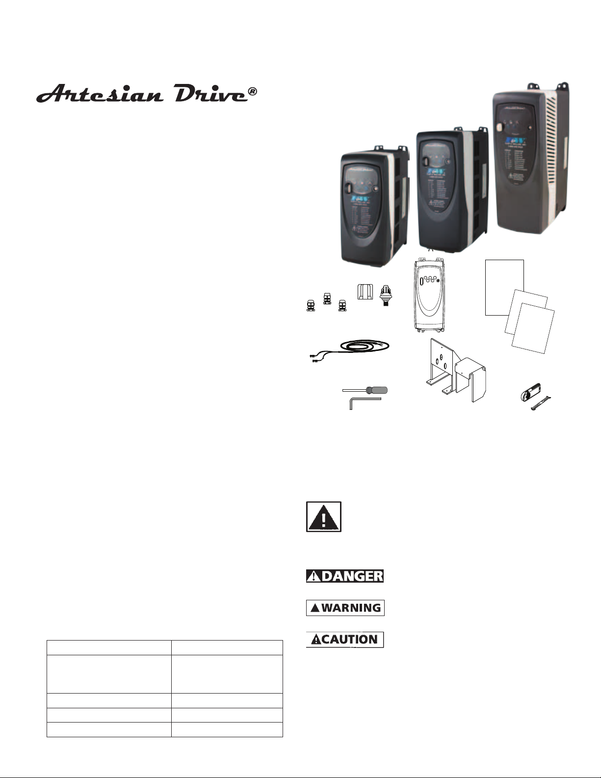
Unpacking
When unpacking the unit, inspect carefully for any damage
that may have occurred during transit.
Included Items:
A. Controller Unit F. Wiring Enclosure
B. Strain Relief Fittings
* Only one fitting w/
AD150145
C. Pressure Sensor and Boot H. Warranty Card
D. Sensor Adjustment Tools I. Installation Guide
E. Sensor Cable J. Installation Manual
G. Memory Stick &
Retainer
95 North Oak St. • Kendallville, IN 46755 • 1-800-345-9422
B
C
E
D
Figure 1
General Safety Information
Carefully read and follow all safety instructions in this
manual and on pump. Keep safety labels in good condi-
tion. Replace missing or damaged safety labels.
this symbol on the pump or in the manual, look for one of
the following signal words and be alert to the potential for
personal injury or property damage.
personal injury, death or major property damage if ignored.
personal injury or death, if ignored.
personal injury, product or property damage if ignored.
IMPORTANT: Indicates factors concerned with operation,
installation, assembly or maintenance which could result in
damage to the machine or equipment if ignored.
NOTE: Indicates special instructions which are important but
are not related to hazards.
1 (FW1086)
This is a SAFETY ALERT SYMBOL. When you see
Warns of hazards that WILL cause serious
Warns of hazards that CAN cause serious
Warns of hazards that MAY cause minor
A
F
FW1086
0411
Supersedes
0809
J
H
I
G
IL0736
022687
Page 2

!
carefully. Failure to follow could result in serious bodily injury
!
!
!
!
!
!
!
!
IL0729
and/or property damage.
controller can still hold a lethal voltage even after power
has been removed. Allow 10 minutes for dangerous internal
voltage to discharge before opening the unit.
capacitors with the Artesian Drive. Damage will result to both
motor and drive.
perform installation.
Read these warnings and instructions
Capacitors inside the Artesian Drive
Do not use power factor correction
Electrical installations
shall be in accordance with National Electric
Code (NEC) and all applicable local codes
and ordinances. A licensed electrician should
Be sure system is connected
to a circuit equipped with a fuse or circuit
breaker of the correct rating.
Always disconnect power
source before performing any work on or near
the controller, motor or its connected load. If
the power disconnect point is out-of-sight, lock
it in the open position and/or tag it to prevent unexpected
application of power. Failure to do so could result in fatal
electrical shock or bodily injury.
DO NOT handle pump with wet
hands or when standing in water as fatal electrical
shock could occur. Disconnect main power supply
before handling system for any reason.
Protect the power cable from
coming in contact with sharp objects, oil, grease,
hot surfaces or chemicals. DO NOT kink the
power cable. If damaged replace immediately.
NEVER leave the control box,
fused disconnect switch, or covers open (either
partially or completely) when not being worked
on by a competent electrician or repairman.
This product contains chemicals known
to the State of California to cause
cancer and birth defects or other reproductive harm.
Do not pump water above 140 degrees
Fahrenheit.
This unit not tested for use
in swimming pool areas.
How it Works
The F&W Artesian Drive is designed to be part of a system
that consists of only four major components:
A. Standard Pump and Three Phase Motor.
B. Artesian Drive Controller.
C. Small Pressure Tank (for tank size, see Table 2).
D. Pressure Sensor (provided).
Power Supply from
Circuit Breaker
Figure 2a - Constant Pressure Diagram for booster pumps
Power to
Motor
Motor
Pump
Outlet
Pressure
Relief Valve
Inlet
Constant Pressure
Diagram
Pressure
Relief Valve
Pump
Outlet
Tank
Tank
Pressure
Sensor
Leads
Pressure
Sensor
Leads
Always use caution when
operating electrical controls in damp areas. If possible,
avoid all contact with electrical equipment during
thunderstorms or extreme damp conditions.
Install all electrical equipment
in protected area to prevent mechanical damage
which could produce serious electrical shock and/
or equipment failure.
DO NOT use this system to pump
flammable liquids such as gasoline, fuel oil, kerosene,
etc. Failure to follow the above warning could result
in property damage and/or personal injury.
95 North Oak St. • Kendallville, IN 46755 • 1-800-345-9422
Power Supply from
Circuit Breaker
Figure 2b - Constant Pressure Diagram for centrifugal pumps
Constant Pressure
The F&W Artesian Drive provides consistent pressure regulation using custom programming to run a standard motor
and pump according to the pressure demands indicated by
a heavy duty pressure switch. By adjusting the motor/pump
speed, the Artesian Drive can deliver consistent pressure
2 (FW1086)
Power
to
Motor
Inlet
Motor
IL0783
Page 3
dependably, even as water demand changes. For example,
!
!
!
!
!
!
a small demand on the system, such as a kitchen faucet,
results in the motor/pump running at a relatively low speed.
As greater demands are placed on the water system, such as
opening additional faucets or using appliances, the motor/
pump speed increases accordingly to maintain the desired system pressure.
MOTOR SOFT START
Whenever the Artesian Drive detects that water is being used,
the controller always “ramps up” the motor speed at the
same time as gradually increasing voltage, resulting in a cooler running motor and lower in-rush current compared to a
motor being used on conventional water systems. If the water
demand is very low, the system may cycle on and off at very
low speeds, but due to the drive’s soft-start feature and pressure switch’s dependable design, this will not harm the motor
or the pressure sensor.
SYSTEM DIAGNOSTICS
In addition to regulating system pressure and accurately
controlling motor operation, the Artesian Drive continuously
scans the system and can detect a variety of abnormal conditions. If there is elevated risk of damage to a part of the system, the drive will protect the system and display a code for
the fault. If possible, the drive will try to restart itself when
the fault condition passes.
PUMP SIZING – ARTESIAN DRIVE (CENTRIFUGAL)
The Artesian Drive is configured at the factory for use with
standard 3-phase motors and pumps.
NOTE: The Artesian Drives are factory programmed to F&W
pumps to provide optimum performance and motor protection. The Artesian Drive can be used with other pumps, but
the maximum motor amperage needs to be compared to the
factory programmed current value (refer to the Specifications
section under the appropriate model). If the maximum motor
current varies more than 5% from the programmed value,
the motor current value in the drive needs to be changed
for motor protection and optimum performance. For details
on how to change this value in the drive, please contact
Technical Support at 1-800-345-9422.
The motor rated current must be set
correctly to avoid a risk of fire in the
event of a motor overload.
DRIVE CONFIGURATION
When sized correctly, the Artesian Drive systems are ready to
go right out of the box and need no configuration. Under
certain circumstances there are several programming parameters that can be changed to accommodate non standard
systems. For further information to change these parameters,
please call Technical Support at 1-800-345-9422
from contact with internal electrical components. DO NOT,
under any circumstances, attempt to modify connections to
the drive until power has been removed and 10 minutes have
passed for internal voltages to discharge!
Serious or fatal electrical shock may result
UNDERLOAD SENSITIVITY
The Artesian Drive controller is configured at the factory
to ensure detection of Underload faults in a wide variety
of pumping applications including dead head and run dry
conditions. In very rare cases (as with certain pumps in shallow wells) this trip level may result in nuisance faults. If the
pump is installed in a shallow well, activate the controller
and observe system behavior. Once the controller begins to
95 North Oak St. • Kendallville, IN 46755 • 1-800-345-9422
regulate pressure, check operation at several flow rates to
make sure the default sensitivity does not induce nuisance
Underload trips. If it becomes necessary to desensitize the
Underload trip level, please call of Technical Support at 1-800345-9422 for further details.
from contact with internal electrical components. DO NOT,
under any circumstances, attempt to modify connections to
the drive until power has been removed and 10 minutes have
passed for internal voltages to discharge!
Serious or fatal electrical shock may result
Before Getting Started
from failure to connect the ground terminal to the motor,
Artesian Drive controller, metal plumbing, or other metal
near the motor or cable, using wire no smaller than motor
cable wires. To minimize risk of electrical shock, disconnect
power before working on or around the Artesian Drive
system. CAPACITORS INSIDE THE ARTESIAN DRIVE CONTROLLER
CAN STILL HOLD LETHAL VOLTAGE EVEN AFTER POWER HAS
BEEN DISCONNECTED. ALLOW 10 MINUTES FOR DANGEROUS
INTERNAL VOLTAGE TO DISCHARGE BEFORE REMOVING
ARTESIAN DRIVE COVER.
areas.
IMPORTANT: This equipment should be installed by technically
qualified personnel. Failure to install it in compliance
with national and local electrical codes and within F&W
recommendations may result in electrical shock hazard, fire
hazard, unsatisfactory performance, or equipment failure.
Installation information is available directly from F&W at our
toll-free number 1-800-345-9422.
three phase motors. Use of this unit with improperly sized
motors may result in damage to both motor and electronics.
Serious or fatal electrical shock may result
Do not use motor or system in swimming
Use Artesian Drive only with properly sized
Controller Location Selection
The drive’s enclosure is NEMA 1 rated
and is intended for indoor use only. It
should be mounted in a location that provides protection
from water spray/drips and only be accessed by trained and
authorized personnel.
The Artesian Drive controller is intended for operation in
ambient temperatures up to 104°F (40°C) at 230 VAC input.
The following recommendations will help in selection of the
proper location of the Artesian Drive unit:
1. A tank tee is recommended for mounting the tank, pressure
sensor, pressure gauge, and pressure relief valve at one
junction. If a tank tee is not used, the pressure sensor should
be located within 6 feet (1.8 meters) downstream of the
pressure tank to minimize pressure fluctuations.
NOTE: There should be no elbows between the tank and pressure sensor and the tank should be between the the pump
and pressure sensor.
2. The unit should be mounted on a sturdy supporting
structure such as a wall or supporting post. Please take into
account the weight of the unit (refer to the Specifications
section under the appropriate model).
3. The electronics inside the Artesian Drive are air-cooled. As a
result, there should be at least 4 inches of clearance on each
side and below the unit to allow room for air flow.
3 (FW1086)
Page 4
clearance on each side and below the unit to allow room for
IL0735
IL0734
air flow.
4”
Min
4” Min
Power Supply from Circuit Breaker
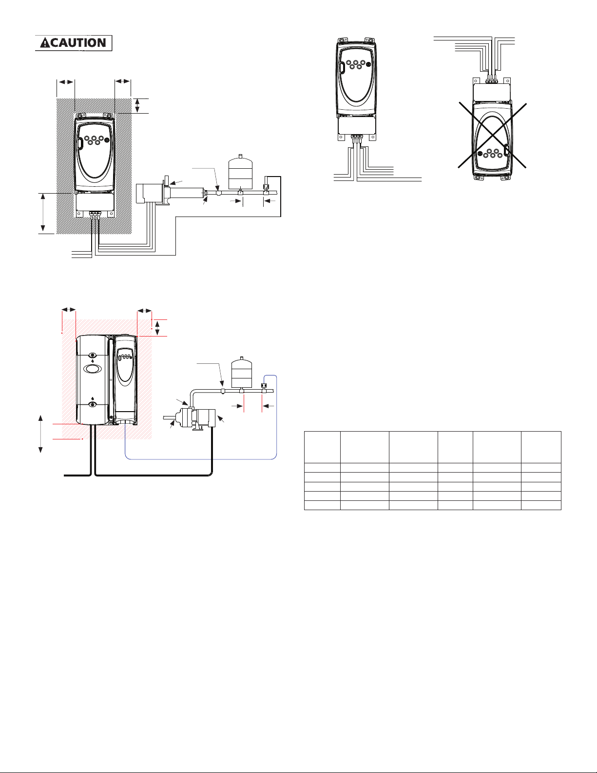
Figure 3a - Mounting Clearance - Booster Pumps
4”
Min
4” Min
Power Supply
from Circuit
Breaker
Figure 3a - Mounting Clearance - Centrifiugal Pumps
There should be at least 4 inches of
4”
Min
4”
Min
Pressure Relief
Valve
Inlet
Motor Pump
Outlet
Pressure Tank to
Power to
Motor
4”
Min
4”
Min
Pressure Relief
Valve
Outlet
Inlet
Power to Motor
Pressure Sensor
Mounting
Clearance
Pump
Motor
Pressure Tank to
Pressure Sensor
Tank
Tank
IL0784
Pressure
Sensor
Leads
6 Ft.
or Less
Pressure
Sensor
Leads
6 Ft.
or Less
4. Do not expose a Artesian Drive to rain or water spray. For
outdoor installations, place the drive inside a NEMA 3R
enclosure. Note: Please reference maxim temperature
ratings listed above.
Pressure
Sensor
Leads
Correct
Power to
Power
Supply
from Circuit
Breaker
Figure 4 - Mounting Orientation
Motor
Mounting Orientation
Pressure
Sensor
Leads
Power
to Motor
Power
Supply
from
Circuit
Breaker
Incorrect
5. The Artesian Drive should only be mounted with the wiring
end oriented downward. The controller should not be placed
in direct sunlight or other locations subject to extreme
temperatures or humidity (mounting location should not be
subjected to freezing conditions or condensation).
6. The mounting location should have access to 230 VAC
electrical supply and to the pump motor wiring. To avoid
possible interference with other appliances, please refer to
the enclosed Installation Guide and observe all precautions
regarding power cable routing.
CIRCUIT BREAKER AND WIRE SIZING
The minimum circuit breaker size and maximum allowable
wire lengths for connection of motor to the Artesian Drive
are given in the following table:
TABLE 1: MINIMUM BREAKER SIZE AND MAXIMUM
CABLE LENGTH (IN FEET)
Drive
Recommended
Model
AD052045 12 16 325 20 5.2
AD070059 12 16 325 25 7.0
AD096074 10 14 325 30 9.6
AD096096 10 14 325 30 9.6
AD150145 8 12 325 30 15.0
Input Cable
Recommended
Motor Cable
Maximum
Cable
Length to
Motor (Ft.)
Recommended
Breaker
Maximum
Continuous
Current
A 10-foot section of cable is provided with the Artesian Drive
to connect the pressure sensor.
NOTE:
• Maximum allowable wire lengths are measured between
the controller and motor.
• Aluminum wires should not be used with the Artesian
Drive.
• Wire sizing between the service entrance and the control-
ler must be sufficient to provide the required maximum
input amps to the controller while conforming to local
standards and codes.
• Artesian Drive minimum breaker amps may appear to
exceed specifications for the three-phase motor because
Artesian Drive controllers are supplied from a singlephase service rather than three-phase.
Pressure Tank
The Artesian Drive needs only a small pressure tank to maintain constant pressure (see table below for recommended
4 (FW1086)
95 North Oak St. • Kendallville, IN 46755 • 1-800-345-9422
Page 5

tank size). The Artesian Drive can also use a bigger tank with
IL0746
!
!
!
a much larger capacity if available.
TABLE 2: MINIMUM PRESSURE TANK
Rated Pump Flow Pressure Tank Size (Total
Volume)
Pump Capacity less than 12
4 Gallon (AT15)
GPM
Pump Capacity greater than
8 Gallon (AT25)
12 but less than 25 GPM
Pump Capacity greater than
14 Gallon (AT44)
25 GPM
The pressure tank pre-charge setting should be 70% of the
system pressure sensor setting as indicated in the following
table.
TABLE 3: PRESSURE TANK AIR PRECHARGE (PSI)
System Pressure (at Pressure
Sensor)
Pressure Tank Precharge
Setting (± 2 PSI)
30 21
35 25
40 28
45 32
50 35
55 39
60 42
65 46
70 49
75 53
80* 56
*NOTE: High pressure applications above 80 PSI should
be addressed through the Tech Support group at Flint &
Walling (1-800-345-9422).
Installation Procedure
1. Disconnect electrical power at the main breaker.
2. Drain the system of water (if applicable).
3. Install the pressure sensor (threaded connection down) at
the pressure tank tee downstream of the pressure tank (the
pressure tank should be between the pressure sensor and
the pump). The pressure sensor has a 1/4-18 National Pipe
Thread (NPT) connection.
NOTE: The pressure sensor should not be installed in an
inverted orientation (threaded connection up). Make sure the
pressure sensor and tank are not located more than 3 feet off
the main piping.
4. The unit should be mounted on a sturdy supporting
structure such as a wall or supporting post. Please take into
account the weight of the unit (refer to the Specifications
section under the appropriate model). Install the unit to the
wall using six mounting screws (not included) as shown in
Figure 5.
H
2-3/8”
W1
W2
Figure 5
TABLE 4: DIMENSIONS
Drive Model H W1 W2
AD052045 7-1/2” 2-3/16” 2-3/16”
AD070058 7-1/2” 2-3/16” 2-3/16”
AD096096 9-1/2” 2-3/4” 2-3/4”
AD150145 12-13/32” 3-13/32” 3-13/32”
Wiring Connections
Serious or fatal electrical shock may result
from failure to connect the motor, the Artesian Drive, metal
plumbing and all other metal near the motor, or cable to the
power supply ground terminal, using wire no smaller than
motor cable wires. To reduce risk of electrical shock, disconnect
power before working on or around the water system.
To avoid a fire hazard and maintain validity
of the UL listing, torque the power terminal screws to 12 lb.-in.
(1.4 N-m).
Do not use motor or system in swimming
areas.
BEFORE BEGINNING WIRING
1. Verify that the power has been shut off at the main breaker.
2. Verify that the dedicated branch circuit for the Artesian
Drive is equipped with a properly-sized circuit breaker. Refer
to Table 2 (Page 8) for minimum breaker size.
3. Insert the provided strain relief into the mounting holes on
the bottom of the enclosure. (Strain relief fittings are not
supplied for the motor supply cable and power supply leads
on AD150145).
4. Remove the Artesian Drive cover. Line up the alignment
notches and slip the memory stick into the slot on the front
of the controller. Note: Do not force the stick into place; it
should slip into the slot and protrude about 3/4” from the
face of the controller with the cover off when fully seated.
5 (FW1086)
95 North Oak St. • Kendallville, IN 46755 • 1-800-345-9422
Page 6

GND
L1
L2
L3
U
V
W
PEPE
IL0731
!
1
2
IL0732
B2
B5
B4
L1 L2 L3 U V W
PE
PE
GND
Output
to
Motor
IL0747
Figure 6
5. Feed the motor supply cable and 230 VAC power leads
through the bottom right and left strain reliefs respectively.
Connect the motor ground and power supply ground wires
the terminal block marked GND and PE respectively.
Because of the leakage current produced
by the internal filtering, permanent fixed ground connections
must be made using two independent conductors each with a
cross-section equal to or exceeding that of the supply conductors. The drive is provided with two ground terminals marked
PE to facilitate this.
6. Connect motor supply leads to terminal block positions
marked U, V and W (right hand side). Connect power leads
to terminals marked L1 and L3 (left hand side).
Note: For correct motor rotation and pump performance on
F&W manufactured motors, leads 1-7, 2-8 & 3-9 on the motor
should be connected to U, V & W respectively. Three phase
motors from other manufactures may require that connection
U & V be switched at the drive for proper motor rotation and
performance.
Figure 8
9. Press the memory stick guard into the slot in the front cover
as shown; do not press fully into position. Replace the front
cover. Do not over-tighten the screw.
IL0779
Figure 9
Remove
Rubber End
Cap to Adjust
Pressure with
7/32” Allen
Wrench
Pressure Sensor
Boot
GND
IL0730
Figure10 - Pressure Sensor
Figure 7
10. Connect the other end of the pressure sensor cable with the
7. Feed the pressure sensor leads through the smaller strain
relief on the bottom of the Artesian Drive unit and connect
the red and black leads to the terminals marked “B2” and
“B5” (interchangeable) with a small screwdriver (provided).
Make sure to not disconnect the factory installed jumper
wire that is already connected to terminal “B2”.
NOTE: A 10-foot section of pressure sensor cable is provided
with the controller, but it is possible to use similar 20 AWG
wire for distances up to 100 feet from the pressure sensor.
8. Slide the lower enclosure cover into position and tighten
screw on bottom lip as show.
6 (FW1086)
95 North Oak St. • Kendallville, IN 46755 • 1-800-345-9422
two spade terminals to the pressure sensor. The connections
are interchangeable.
11. Set the pressure tank pre-charge at 70% of the desired
water pressure setting. To check the tank’s pre-charge, depressurize the water system by opening a tap. Measure the
tank pre-charge with a pressure gauge at its inflation valve
and make the necessary adjustments.
12. The pressure sensor communicates the system pressure to
the Artesian Drive controller. The sensor is preset at the
factory to 50 psi, but can be adjusted by the installer using
Page 7
the following procedure:
!
a. Remove the rubber end-cap.
b. Using a 7/32” Allen wrench (provided), turn the adjusting
screw clockwise to increase pressure and counterclockwise to decrease pressure. The adjustment range is
between 30 and 80 psi (1/4 turn = approximately 3 psi).
c. Replace the rubber end cap.
d. Reset the pressure tank pre-charge to the appropriate
pressure.
e. Cover the pressure sensor terminals with the rubber boot
provided.
exceed the mechanical stop on the pressure sensor or 80 psi.
When increasing the pressure, do not
The pressure sensor may be damaged.
NOTE: Ensure that the system is properly grounded all the
way to the service entrance panel. Improper grounding may
result in the loss of voltage surge protection and interference
filtering.
SPECIAL INSTRUCTIONS FOR OUTDOOR INSTALLATION
To install the Artesian Drive in an outdoor installation,
the drive must be placed inside NEMA 3R enclosure (Not
Included).
Start-Up and Operation
Apply power to the controller. As long as the display is lit up
the system has power. When the display shows . or
DIAGNOSTIC FAULT CODES
Should an application or system problem occur, built-in diagnostics will protect the system. The display will change to
indicate the nature of the fault. In some cases, the system will
shut itself off until corrective action has been taken. Fault
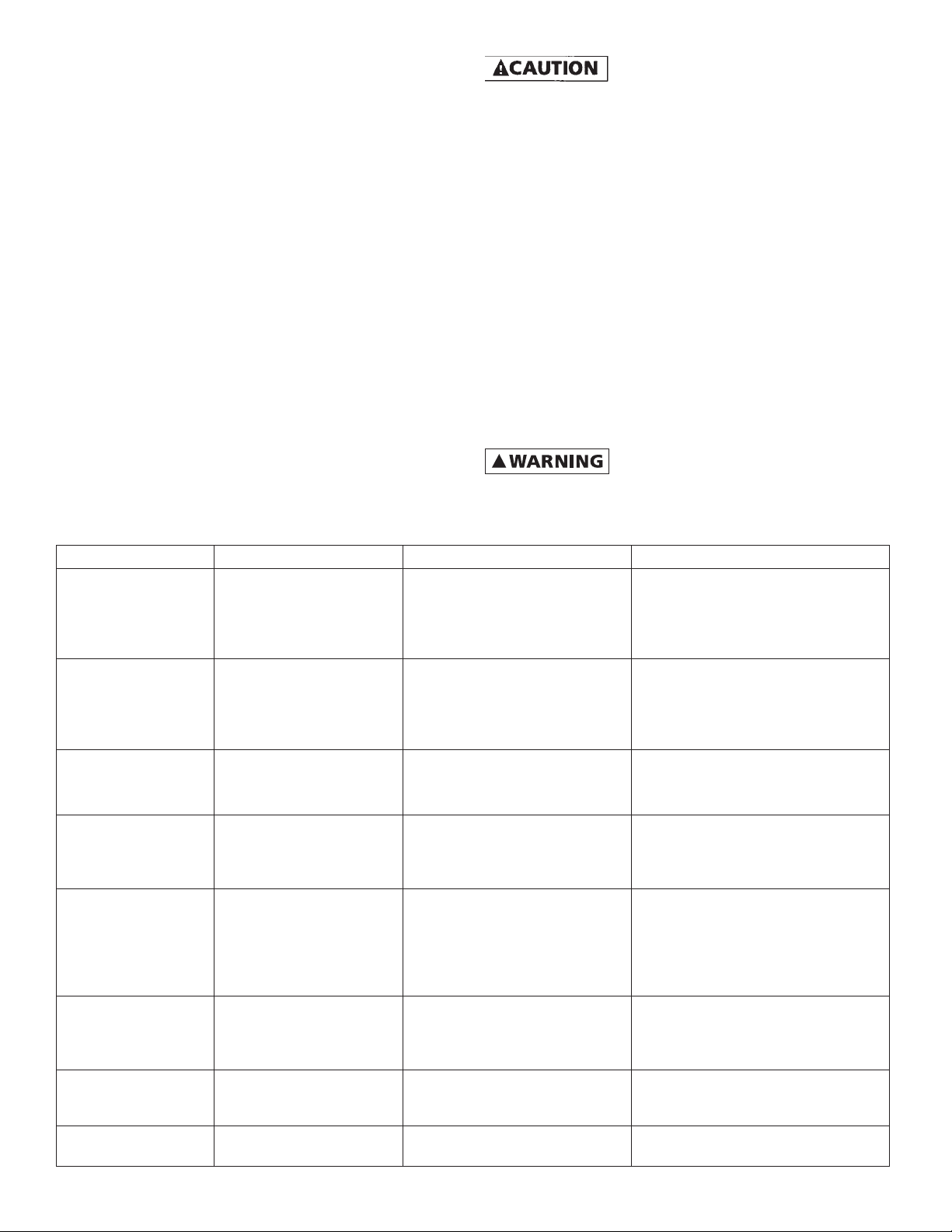
TABLE 5: DIAGNOSTIC FAULT CODES
DISPLAY CODE FAULT POSSIBLE CAUSE CORRECTIVE ACTION
. Locked Pump Motor/pump misaligned.
. Short Circuit When fault is indicated imme-
. Over Current When fault is indicated while
.
(Number other than
0.0 & motor is not
running)
. . Overheated Controller High ambient temperature.
. Controller Stopped Loose jumper wire Re-insert jumper wire into control
Motor Underload Air-locked pump. Overpumped
Undervoltage Low line voltage. Misconnected
Open Circuit Loose connection. Defective
95 North Oak St. • Kendallville, IN 46755 • 1-800-345-9422
codes and the recommended corrective action for each are
listed in the following chart.
supplier for repair.
or dry well. Worn pump.
Damaged shaft or coupling.
Pump deadhead. Blocked pump
or screen.
input leads.
Abrasive/Sand-bound pump.
Dragging pump or motor.
diately after power-up, short
circuit due to loose connection,
defective cable, splice or motor.
motor is running, over current
due to loose debris trapped
in pump, or water demand is
exceeding pump & motor’s capability.
motor or cable.
Direct sunlight. Obstruction of
air-flow.
7 (FW1086)
Do not attempt to carry out internal
repairs. Return a faulty drive to the
Wait for well to recover and automatic restart timer to time out. If
the problem does not correct, check
motor and pump. See description of
“Intelligent Reset” on Page 18.
Check for loose connections. Check
line voltage. Report low voltage
to the power company. Unit will
start automatically when the proper
power is supplied.
Unit will attempt to free a locked
pump. If unsuccessful, check the
motor and pump.
Check motor wiring. Turn power off
till display darkens then apply power
again to reset.
Check pump.
With power off, check motor, motor
wiring and splices. Make certain all
connections are tight. Apply power
again to reset.
This fault automatically resets when
the temperature returns to a safe
level.
terminals B2 & B4.
Page 8

TABLE 6 SYSTEM TROUBLESHOOTING GUIDE
Symptom Possible Cause Corrective Action
Motor/Pump is running backwards. Reverse connection of motor cable wires at connection
point U & V.
Pump capacity cannot supply the demand. Use pump with higher flow rating (if head requirement is
still satisfied).
Water flow rate
is not as high as
expected.
Temperature in the controller is too high. If
the controller’s heat exchanger becomes too
hot, the controller will reduce the switching
frequency to the motor to lower the power
Make sure there is at least 4 inches of room around the
controller for movement of air. Avoid direct sunlight.
Reduce ambient temperature below 104°F (40°C). Increase
input voltage if below 230 VAC.
consumption.
Disconnected or broken wire feeding motor. Check motor, motor wiring and splices. Make certain all
connections are tight.
Waterlogged tank. Check tank for bladder damage. Replace if necessary.
Excessive pressure fluctuations.
Motor runs continuously with
no flow demand.
Pressure tank is too small for flow rating of
the pump.
Leak in the household or outdoor plumbing. Check for leaky faucets, valves and/or pipe fittings and
Leak in the pitless adapter. Re-seat the pitless adapter. Replace seal as needed.
Reset the tank pre-charge pressure (should be 70% of pressure sensor setting).
Use larger tank (refer to Table 3 on Page 4 for minimum
Pressure Tank size).
repair.
flashes PLC as shown, the system is active, but the pump is not
running. The display will show . as shown (where the
numbers may be fluctuating) when the pump is running.
IL0748
Figure 11
LEAKY SYSTEMS
Leaky water systems might keep the controller running due to
the accurate pressure sensing capability of the pressure sensor. Continuous running or starts and stops do not hurt the
controller, pump or motor. However, to reduce the on-time
of the controller/pump/motor, a “Bump-Mode” procedure
has been programmed into the drive. During very low flow
(or leaky) conditions this feature periodically increases the
speed of the pump several PSI above the set point and shuts
off the pump. This adds some time to bleed off before the
system starts up again. This “Bump-Mode” can be turned off
if desired. Please call Technical Support at 1-800-345-9422 for
further details.
NOTE: Artesian Drive maintains a constant pressure at the
pressure sensor. Although the pressure is constant at the
pressure sensor, pressure drops may be noticeable in other
areas of the system when additional taps are opened. This
is due to restrictions in the plumbing and will be more pronounced the farther the taps are from the pressure sensor.
This would be true of any system, and if observed, should not
be interpreted as a failure in the performance of the Artesian
Drive.
8 (FW1086)
95 North Oak St. • Kendallville, IN 46755 • 1-800-345-9422
Although the pressure sensor can be adjusted up to 80 PSI,
the maximum obtainable pressure in the system is dependent
upon the full load capability of the pump at a given flow. For
example, a pump is only capable of producing a pressure of
60 PSI at the flow demand. Increasing the pressure setting of
the pressure sensor to 75PSI would only result in the pump
running at full speed and producing a pressure of 60 PSI.
UNDERLOAD INTELLIGENT RESET
(Display showing )
If a motor Underload fault condition occurs, the most likely
cause is an overpumped well (dry well) or loss of incoming
feed water to the pump. In a dry well situation to allow the
well to recover, the Artesian Drive controller will wait 30
seconds to 5 minutes, determined by the amount of time
the motor had been running before sensing the underload,
before restarting the motor. For example, the first time the
fault occurs and the pump has been running 6 minutes, the
controller stops the motor and will wait 30 seconds before
attempting to restart the pump. If the system would then run
for 2 minutes and an underload fault recurs, the controller
will wait 3 minutes before attempting to restart the pump.
This schedule allows for the minimum off-time possible based
on the recovery time of the well or water feed supply.
If there is an obstruction (such as a closed valve) between the
pump and the pressure sensor, the controller will also sense
an underload is this “dead head” condition stopping the
motor to avoid damaging the pump.
Page 9

6.0
5.0
4.0
3.0
2.0
Off Time (Min.)
1.0
0.0
0 1 2 3 4 5 6 7 8
Run Time (Min.)
IL0750
Figure 12
OVER-TEMPERATURE
The Artesian Drive controller is designed for full power operation in ambient temperatures up to 104°F (40°C) as long as
the input voltage is kept at 230 VAC. Under extreme thermal
conditions, the controller will reduce the switching frequency
in an attempt to avoid shutdown. If the temperature of the
controller is still too hot the controller will shut itself off to
avoid causing damage to itself. Full pump output is restored
when the controller temperature cools to a safe level.
NOTE: The Artesian Drives are factory programmed to
F&W pumps to provide optimum performance and motor
protection. The Artesian Drive can be used with other
pumps, but the maximum motor amperage needs to be
compared to the factory programmed current value (refer
to the Specifications section under the appropriate model).
If the maximum motor current varies more than 5% from
the programmed value, the motor current value in the drive
needs to be changed for motor protection and optimum
performance. For details on how to change this value in the
drive, please contact Technical Support at 1-800-345-9422.
DRIVE SPECIFICATIONS AND DIMENSIONS
Model Number AD052045 AD070059 AD096074 AD096096 AD150145
Voltage 180 -264 AC (Single or Three Phase)
Input from power
source
Output to Motor
(Three Phase )
For Use With
Pressure Setting
Operating
Conditions
Controller Size NEMA 1 ( indoor ) 10.47” H x 3.35” W x 6.15” D 12.54” H x 3.94” W x 6.90” D 15.60” x 4.48” x 8.05”
Weight 2.9 lbs. 3.1 lbs. 4.6 lbs. 4.6 lbs. 9.9 lbs.
RMS = ROOT MEAN SQUARED
* The electrical characteristics of motors vary slightly. See Amp draw on motor nameplate. If the maximum motor current value (Amp draw) is more than 5% of the programmed value of the Drive, the Drive will need to be set to the
current value of the motor to provide proper protection..
Frequency 50/60 Hz
Current (Max) - RMS
Power Factor 1.0 ( constant )
Voltage Voltage Automatically Adjust with Frequency (0 thru 230 Volts)
Frequency Range 15 - 60 Hz
Current, Factory Programmed*
(RMS, Each Phase)
Current (Max)
(RMS, Each Phase)
Motor Standard 60 Hz. Pump & 230 Volt 3 Phase Motor Combination
Reference HP Rating* 1 1.5 2 3 5
Factory preset 50 PSI
Adjustable Range 30 - 80 PSI
Temperature
(@ 230 VAC input)
Relative Humidity Max 95% Non-condensing
14.2 Amps 1ø
(6.7 Amps 3ø)
4.5 Amps 5.9 Amps 7.4 Amps 9.6 Amps 14.5 Amps
5.2 Amps 7.0 Amps 9.6 Amps 9.6 Amps 15.0 Amps
17.4 Amps 1ø
(8.7 Amps 3ø)
23.2 Amps 1ø
(11.9 Amps 3ø)
10° to 40° C ( 14° to 104° F. )
23.2 Amps 1ø
(11.9 Amps 3ø)
29.5 Amps 1ø
(15.7 Amps 3ø)
9 (FW1086)
95 North Oak St. • Kendallville, IN 46755 • 1-800-345-9422
Page 10

Quick Reference Guide to Controller
!
Installation
(Item not to scale)
of passing full pump flow at 100 psi. Install the pressure relief
valve between the pump and pressure tank.
pressure resulting in equipment and property damage as well
Many pumps can develop excessive
as possible injury. Always install a pressure relief valve capable
Mounting Screw
Locations
Power Supply
Connections
B2
B5B4
Pressure
Sensor Lead
Connections
L2
L1
L3
Mounting Screw
Locations
Power Supply from
Circuit Breaker
U
V
W
PEPE
B2
B4
B5
GND
L2
L3
L1
U
V
W
L2
L3
L1
PEPE
U
V
W
PEPE
GND
Motor Lead
Connections
GND
Power to Motor
Figure 13a - Quick Reference Guide to Controller Installation Booster Pumps
95 North Oak St. • Kendallville, IN 46755 • 1-800-345-9422
Pressure Sensor Leads
10 (FW1086)
Page 11
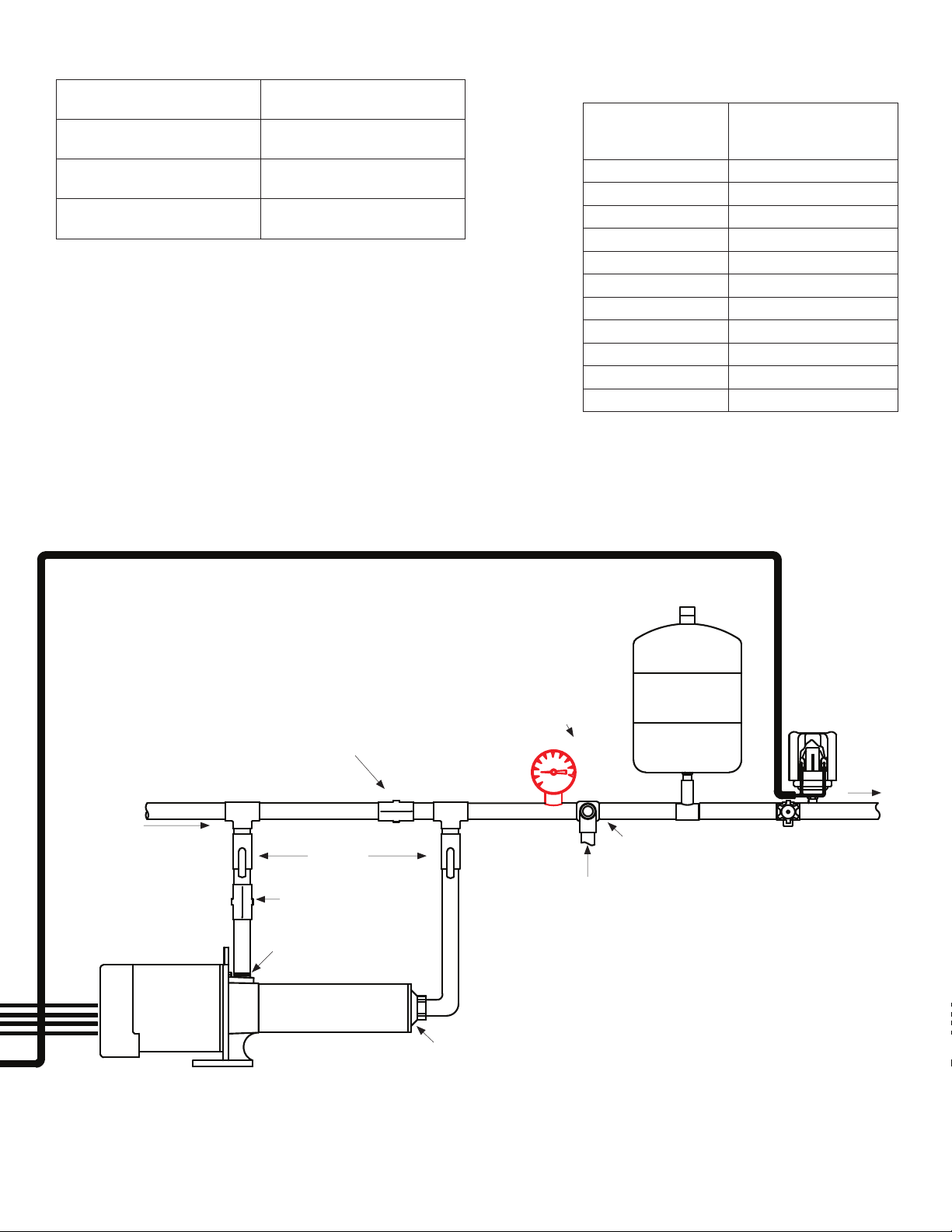
TABLE 2: MINIMUM PRESSURE TANK
Rated Pump Flow Pressure Tank Size (Total
Volume)
Pump Capacity less than 12
4 Gallon (AT15)
GPM
Pump Capacity greater than
8 Gallon (AT25)
12 but less than 25 GPM
Pump Capacity greater than
14 Gallon (AT44)
25 GPM
The pressure tank pre-charge setting should be 70% of the system pressure
sensor setting as indicated in the following table.
TABLE 3: PRESSURE TANK AIR PRECHARGE
(PSI)
System Pressure (at
Pressure Sensor)
Pressure Tank
Precharge Setting (± 2
PSI)
30 21
35 25
40 28
45 32
50 35
55 39
60 42
65 46
70 49
75 53
80 56
*NOTE: High pressure applications above 80
PSI should be addressed through the Tech
Support group at Flint & Walling (1-800-345-
9422).
GND
From Municipal
Motor
Pressure Sensor Cable (Included)
Check Valve
Isolation
Valves
Check Valve
Inlet
Pump
Tank Precharge
Inflation Valve
Pressure
Tank
Pressure
Gauge
Pressure Relief
Valve
Discharge into drain rated for max pump output at
relief pressure
Drain Valve
Pressure
Sensor
To
Service
Outlet
11 (FW1086)
95 North Oak St. • Kendallville, IN 46755 • 1-800-345-9422
IL0733
Page 12

B2B4B5
Pressure Sensor
Connections
B5
B4
B2
Power Supply
Connections
GND
GND
Figure 13b - Quick Reference Guide to Controller Installation Centrifugal Pumps
Motor Lead
Connections
12 (FW1086)
95 North Oak St. • Kendallville, IN 46755 • 1-800-345-9422
Page 13

Pressure Sensor Cable (Included)
Tank Precharge
Inflation Valve
From Municipal
Isolation
Valves
Check Valve
Pump
Inlet
Check Valve
Pressure
Gauge
Outlet
Motor
Discharge
into drain
rated for
max pump
output
at relief
pressure
Pressure
Tank
Pressure
Relief
Valve
Drain
Valve
Pressure
Sensor
To
Service
13 (FW1086)
95 North Oak St. • Kendallville, IN 46755 • 1-800-345-9422
IL0789
 Loading...