

Page 1
19 August 2014
To buy, sell, rent or trade-in this product please click on the link below:
https://www.avionteq.com/Flight-Data-Systems-HHMPI-FSD40-Data-Transfer-Unit.aspx
www.avionteq.com
30-0005 Issue D
Operators manual
Handheld Multi-Purpose Interface (HHMPI)
Flight Data Systems Pty Ltd
31 McGregors Drive, Keilor Park,
Victoria 3042, Australia.
Ph. +61 3 8331 2900
Fax. +61 3 9336 1751
Email: [email protected]
Copyright © Flight Data Systems 2014
This manual is property of Flight Data Systems. This manual contains information in
which Flight Data Systems has a protected interest. This manual is a controlled document
and as such is subject to amendment. It is in the interest of the user to register this manual with Flight Data Systems to ensure receipt of any amendments. The use, duplication,
and/or disclosure, by persons receiving this manual may be subject to restrictions. No
part of this document and/or data contained herein may be reproduced and/or used in
any form without written permission from Flight Data Systems.
Page 2

Contents
Contents
Record of changes 4
List of figures 4
List of tables 5
2.0 Introduction 5
2.1 HHMPI models. . . . . . . . . . . . . . . . . . . . . . . . . . . . . . . . . . . 6
2.2 HHMPI equipment . . . . . . . . . . . . . . . . . . . . . . . . . . . . . . . 9
3.0 Getting started 12
3.1 Terminology used in this manual. . . . . . . . . . . . . . . . . . 12
3.2 Using the HHMPI. . . . . . . . . . . . . . . . . . . . . . . . . . . . . . . . 13
3.2.1 Connecting the HHMPI to an FDR . . . . . . . . . . . . . . . 13
3.2.2 Powering and charging the HHMPI . . . . . . . . . . . . . . 14
3.2.3 Charging the HHMPI with the docking cradle . . . . . 15
3.2.4 Turning on the HHMPI and self-test. . . . . . . . . . . . . . 16
3.2.5 Reset operation . . . . . . . . . . . . . . . . . . . . . . . . . . . . . . . 16
3.3 Shortcuts. . . . . . . . . . . . . . . . . . . . . . . . . . . . . . . . . . . . . . . 17
3.4 Menu structure . . . . . . . . . . . . . . . . . . . . . . . . . . . . . . . . . 17
3.5 HHMPI configuration . . . . . . . . . . . . . . . . . . . . . . . . . . . . 17
2.3 Accessories. . . . . . . . . . . . . . . . . . . . . . . . . . . . . . . . . . . . . 10
2.4 Specifications. . . . . . . . . . . . . . . . . . . . . . . . . . . . . . . . . . . 10
3.5.1 Clock Settings. . . . . . . . . . . . . . . . . . . . . . . . . . . . . . . . . 17
3.5.2 Display Settings . . . . . . . . . . . . . . . . . . . . . . . . . . . . . . . 17
3.5.3 Memory Settings . . . . . . . . . . . . . . . . . . . . . . . . . . . . . . 17
3.5.4 Network Settings . . . . . . . . . . . . . . . . . . . . . . . . . . . . . . 18
3.5.5 Aircraft Settings . . . . . . . . . . . . . . . . . . . . . . . . . . . . . . . 18
3.5.6 Security Settings. . . . . . . . . . . . . . . . . . . . . . . . . . . . . . . 18
3.5.7 Live Data Settings . . . . . . . . . . . . . . . . . . . . . . . . . . . . . 18
3.5.8 Shortcut Keys . . . . . . . . . . . . . . . . . . . . . . . . . . . . . . . . . 18
3.5.9 Settings Profile . . . . . . . . . . . . . . . . . . . . . . . . . . . . . . . . 18
3.6 Information . . . . . . . . . . . . . . . . . . . . . . . . . . . . . . . . . . . . 19
4.0 Operation 19
4.1 Download file name . . . . . . . . . . . . . . . . . . . . . . . . . . . . . 19
4.2 Aircraft lists. . . . . . . . . . . . . . . . . . . . . . . . . . . . . . . . . . . . . 19
4.2.1 Loading aircraft details . . . . . . . . . . . . . . . . . . . . . . . . . 19
4.2.2 Creating an Aircraft List on a PC . . . . . . . . . . . . . . . . . 20
4.2.3 Transferring the Aircraft List to the HHMPI. . . . . . . . 20
4.2.4 Creating the Aircraft List on the HHMPI . . . . . . . . . . 21
4.2.5 Adding Entries to the HHMPI Aircraft File . . . . . . . . . 21
4.2.6 Deleting an aircraft from the Aircraft list on the HHMPI
21
4.2.7 Saving the Aircraft list to the USB flash drive on the
HHMPI . . . . . . . . . . . . . . . . . . . . . . . . . . . . . . . . . . . . . . . . . . . . 22
4.2.8 Deleting all aircraft from the Aircraft list on the HHMPI
22
4.2.9 Prompt for Tail No. . . . . . . . . . . . . . . . . . . . . . . . . . . . . 22
4.3 Downloading flight data . . . . . . . . . . . . . . . . . . . . . . . . . 23
4.3.1 Downloading recorded data from the FDR to a USB
flash drive . . . . . . . . . . . . . . . . . . . . . . . . . . . . . . . . . . . . . . . . . 23
4.3.2 Decompressing CVR data at the aircraft . . . . . . . . . . 24
4.3.3 Decompressing CVR away from the aircraft . . . . . . . 25
4.3.4 Using the CVR rack adapter . . . . . . . . . . . . . . . . . . . . . 26
4.4 Viewing live flight data . . . . . . . . . . . . . . . . . . . . . . . . . . 26
4.4.1 Live Data View Options. . . . . . . . . . . . . . . . . . . . . . . . . 28
4.4.2 Adjusting ARINC 717 settings . . . . . . . . . . . . . . . . . . . 28
4.4.3 Changing the display format . . . . . . . . . . . . . . . . . . . . 28
4.5 Viewing live flight data in engineering units . . . . . . . . 29
4.5.1 Assigning an Aircraft Definition file to an aircraft . . 30
4.5.2 Viewing Live Flight Data . . . . . . . . . . . . . . . . . . . . . . . . 30
4.6 File transfer operations . . . . . . . . . . . . . . . . . . . . . . . . . . 32
4.6.1 File transfer between HHMPI storage locations . . . . 32
4.6.2 Other storage operations. . . . . . . . . . . . . . . . . . . . . . . 33
4.6.3 File transfer PC to HHMPI. . . . . . . . . . . . . . . . . . . . . . . 33
4.7 Network operations . . . . . . . . . . . . . . . . . . . . . . . . . . . . . 33
4.7.1 DHCP network settings. . . . . . . . . . . . . . . . . . . . . . . . . 33
5.0 Configuring an FTP connection 34
2 Operators manual
Handheld Multi-Purpose Interface (HHMPI)
Page 3

Contents
5.1 Adding a new FTP server from the HHMPI. . . . . . . . . . 34
5.2 Configuring an existing FTP server from the HHMPI . 35
5.3 Testing an FTP server from the HHMPI . . . . . . . . . . . . . 37
5.4 Setting up an FTP connection from the web interface. .
37
5.4.1 Changing the HHMPI configuration via the web inter-
face . . . . . . . . . . . . . . . . . . . . . . . . . . . . . . . . . . . . . . . . . . . . . . 39
5.4.2 Backing up the HHMPI configuration . . . . . . . . . . . . 40
5.4.3 Restoring backup files via the web interface . . . . . . 41
5.4.4 Administration settings. . . . . . . . . . . . . . . . . . . . . . . . . 41
5.4.5 Logging out of the web interface . . . . . . . . . . . . . . . . 41
6.0 Wirelessly uploading files from the HHMPI to a server 42
6.1 Setting up a wireless network connection . . . . . . . . . . 42
6.1.1 Required equipment and wireless network information
42
6.1.2 Turning on wireless network support. . . . . . . . . . . . . 42
6.1.3 Connecting to a wireless network. . . . . . . . . . . . . . . . 43
6.1.4 Uploading files via FTP with a wireless network connec-
tion. . . . . . . . . . . . . . . . . . . . . . . . . . . . . . . . . . . . . . . . . . . . . . . 44
7.0 Troubleshooting 44
8.0 FA2100, FA2200 and FA2300 Interface Supplement 48
8.1 Download Operations . . . . . . . . . . . . . . . . . . . . . . . . . . . 48
8.2 Recorder Operations . . . . . . . . . . . . . . . . . . . . . . . . . . . . 48
8.3 FDR Status . . . . . . . . . . . . . . . . . . . . . . . . . . . . . . . . . . . . . 49
8.4 CVR Status . . . . . . . . . . . . . . . . . . . . . . . . . . . . . . . . . . . . . 49
8.5 FDR or CVR Fault Output. . . . . . . . . . . . . . . . . . . . . . . . . 49
8.6 Clear Latched Fault . . . . . . . . . . . . . . . . . . . . . . . . . . . . . . 49
8.7 Clear Fault Log. . . . . . . . . . . . . . . . . . . . . . . . . . . . . . . . . . 49
8.8 Dump Fault Log. . . . . . . . . . . . . . . . . . . . . . . . . . . . . . . . . 49
8.9 Dump Debug Trace . . . . . . . . . . . . . . . . . . . . . . . . . . . . . 49
8.10 Memory Marker . . . . . . . . . . . . . . . . . . . . . . . . . . . . . . . 49
8.11 Audio Operations . . . . . . . . . . . . . . . . . . . . . . . . . . . . . . 50
8.12 Live Data View. . . . . . . . . . . . . . . . . . . . . . . . . . . . . . . . . 50
8.13 Menu Tree . . . . . . . . . . . . . . . . . . . . . . . . . . . . . . . . . . . . 50
9.0 SRVIVR Interface Supplement 51
9.1 Download Operations . . . . . . . . . . . . . . . . . . . . . . . . . . . 51
9.2 Recorder Operations . . . . . . . . . . . . . . . . . . . . . . . . . . . . 52
9.3 Audio Operations . . . . . . . . . . . . . . . . . . . . . . . . . . . . . . . 53
9.4 Live Data View. . . . . . . . . . . . . . . . . . . . . . . . . . . . . . . . . . 53
9.5 Menu Tree . . . . . . . . . . . . . . . . . . . . . . . . . . . . . . . . . . . . . 54
10.0 FA5000/FA5001 Interface Supplement 55
10.1 Download Operations . . . . . . . . . . . . . . . . . . . . . . . . . . 55
10.2 Recorder Operations . . . . . . . . . . . . . . . . . . . . . . . . . . . 56
10.3 FDR Configuration . . . . . . . . . . . . . . . . . . . . . . . . . . . . . 57
10.4 Audio Operations . . . . . . . . . . . . . . . . . . . . . . . . . . . . . . 57
10.5 Live Data View. . . . . . . . . . . . . . . . . . . . . . . . . . . . . . . . . 58
10.6 Menu Tree . . . . . . . . . . . . . . . . . . . . . . . . . . . . . . . . . . . . 58
11.0 SMITHS VADR Interface Supplement 60
11.1 Select Aircraft . . . . . . . . . . . . . . . . . . . . . . . . . . . . . . . . . 60
11.2 Download Operations . . . . . . . . . . . . . . . . . . . . . . . . . . 60
11.3 FDR Configuration . . . . . . . . . . . . . . . . . . . . . . . . . . . . . 60
11.4 Upload OFP to the HHMPI . . . . . . . . . . . . . . . . . . . . . . 60
Operators manual 3
FDS 400-301
Page 4

Record of changes
1.0 Record of changes
Table 1.0 Record of changes
Issue Date Comments
4 24 June 2011 New issue
5 20 July 2011 Added battery pack description
Added PCMCIA card description
Added appendices
6 9 September 2011 Added FTP setup
Added wireless USB
Added updated live data view
Added troubleshooting
Issue B 12 November 2013 Added CVR decompression instructions
Added CVR adapter instructions
Added HHMPI cradle features
Added aircraft settings
Issue C 3 December 2013 Updated references
Added screen captures to upload VADAR
Program
MOD table update
Issue D 22 May 2014 Updated layout
Added Engineering Units section
List of figures
Figure 1.0 HHMPI front view. . . . . . . . . . . . . . . . . . . . . . . . . . . . . . . . . . . . . . . . . . . . . . . . 6
Figure 2.0 HHMPI top view. . . . . . . . . . . . . . . . . . . . . . . . . . . . . . . . . . . . . . . . . . . . . . . . . 7
Figure 3.0 HHMPI bottom view . . . . . . . . . . . . . . . . . . . . . . . . . . . . . . . . . . . . . . . . . . . . . 7
Figure 4.0 HHMPI Mod 1 top view . . . . . . . . . . . . . . . . . . . . . . . . . . . . . . . . . . . . . . . . . . 8
Figure 5.0 HHMPI Mod 1 bottom view. . . . . . . . . . . . . . . . . . . . . . . . . . . . . . . . . . . . . . . 8
Figure 6.0 HHMPI kit . . . . . . . . . . . . . . . . . . . . . . . . . . . . . . . . . . . . . . . . . . . . . . . . . . . . . . 9
Figure 7.0 Connecting the HHMPI to the FDR or CVR . . . . . . . . . . . . . . . . . . . . . . . . . 14
Figure 8.0 The Battery Status screen . . . . . . . . . . . . . . . . . . . . . . . . . . . . . . . . . . . . . . . . 15
Figure 9.0 HHMPI power-on sequence. . . . . . . . . . . . . . . . . . . . . . . . . . . . . . . . . . . . . . 16
Figure 10.0 Creating an Aircraft List in Notepad. . . . . . . . . . . . . . . . . . . . . . . . . . . . . . . 20
Figure 11.0 Adding aircraft to the Aircraft List on the HHMPI . . . . . . . . . . . . . . . . . . . 21
Figure 12.0 Configuring the prompt for tail number option . . . . . . . . . . . . . . . . . . . . 23
Figure 13.0 Downloading progress bar. . . . . . . . . . . . . . . . . . . . . . . . . . . . . . . . . . . . . . . 24
Figure 14.0 Downloading and decompressing CVR data . . . . . . . . . . . . . . . . . . . . . . . 25
Figure 15.0 Decompressing Honeywell CVR file away from the aircraft. . . . . . . . . . . 26
Figure 16.0 Viewing live data . . . . . . . . . . . . . . . . . . . . . . . . . . . . . . . . . . . . . . . . . . . . . . . 27
Figure 17.0 ARINC 717 settings . . . . . . . . . . . . . . . . . . . . . . . . . . . . . . . . . . . . . . . . . . . . . 28
Figure 18.0 Multiple live data view . . . . . . . . . . . . . . . . . . . . . . . . . . . . . . . . . . . . . . . . . . 29
Figure 19.0 Word offset adjust . . . . . . . . . . . . . . . . . . . . . . . . . . . . . . . . . . . . . . . . . . . . . . 29
Figure 20.0 Selected tail number on the shortcut screen . . . . . . . . . . . . . . . . . . . . . . . 31
Figure 21.0 Changing from Raw Mode to EU Mode. . . . . . . . . . . . . . . . . . . . . . . . . . . . 31
Figure 22.0 Accessing aircraft parameters alphabetically . . . . . . . . . . . . . . . . . . . . . . . 32
Figure 23.0 Four parameters populated with Engineering Units . . . . . . . . . . . . . . . . . 32
Figure 24.0 DHCP or manual IP configuration. . . . . . . . . . . . . . . . . . . . . . . . . . . . . . . . . 34
Figure 25.0 Setting up the FTP client . . . . . . . . . . . . . . . . . . . . . . . . . . . . . . . . . . . . . . . . 35
Figure 26.0 FTP type menus . . . . . . . . . . . . . . . . . . . . . . . . . . . . . . . . . . . . . . . . . . . . . . . . 36
Figure 27.0 Login, password, remote path and FTP test . . . . . . . . . . . . . . . . . . . . . . . . 37
4 Operators manual
Handheld Multi-Purpose Interface (HHMPI)
Page 5

List of tables
Figure 28.0 Viewing the wired IP address . . . . . . . . . . . . . . . . . . . . . . . . . . . . . . . . . . . . 38
Figure 29.0 Web interface login. . . . . . . . . . . . . . . . . . . . . . . . . . . . . . . . . . . . . . . . . . . . . 38
Figure 30.0 Web interface screen . . . . . . . . . . . . . . . . . . . . . . . . . . . . . . . . . . . . . . . . . . . 39
Figure 31.0 Device configuration screen . . . . . . . . . . . . . . . . . . . . . . . . . . . . . . . . . . . . . 40
Figure 32.0 Device configuration screen . . . . . . . . . . . . . . . . . . . . . . . . . . . . . . . . . . . . . 40
Figure 33.0 Device configuration screen . . . . . . . . . . . . . . . . . . . . . . . . . . . . . . . . . . . . . 41
Figure 34.0 Logout button . . . . . . . . . . . . . . . . . . . . . . . . . . . . . . . . . . . . . . . . . . . . . . . . . 42
Figure 35.0 Connecting to a wireless network. . . . . . . . . . . . . . . . . . . . . . . . . . . . . . . . . 43
Figure 36.0 Configuring security settings like the encryption type and key . . . . . . . 44
Figure 37.0 FA2100 Recorder Operations - Dump Debug Trace . . . . . . . . . . . . . . . . . 49
Figure 38.0 CVR Live Audio volume control. . . . . . . . . . . . . . . . . . . . . . . . . . . . . . . . . . . 50
Figure 39.0 SRVIVR Download Operations. . . . . . . . . . . . . . . . . . . . . . . . . . . . . . . . . . . . 52
Figure 40.0 SRVIVR Recorder Operations - Information . . . . . . . . . . . . . . . . . . . . . . . . 53
Figure 41.0 SRVIVR Recorder Operations - Self Test . . . . . . . . . . . . . . . . . . . . . . . . . . . 53
Figure 42.0 FA5000/FA5001 Download Operations . . . . . . . . . . . . . . . . . . . . . . . . . . . . 56
Figure 43.0 FA5000/FA5001 Recorder Operations - FDR Status . . . . . . . . . . . . . . . . . . 57
Figure 44.0 FA5000/FA5001 Recorder Operations - Dump Log . . . . . . . . . . . . . . . . . . 57
Figure 45.0 CVR Live Audio volume control. . . . . . . . . . . . . . . . . . . . . . . . . . . . . . . . . . . 58
Figure 46.0 VADR information . . . . . . . . . . . . . . . . . . . . . . . . . . . . . . . . . . . . . . . . . . . . . . 60
Figure 47.0 Uploading OFP to the VADR from the HHMPI . . . . . . . . . . . . . . . . . . . . . . 61
List of tables
Table 1.0 Record of changes. . . . . . . . . . . . . . . . . . . . . . . . . . . . . . . . . . . . . . . . . . . . . . . 4
Table 2.0 HHMPI models and description of modifications applied . . . . . . . . . . . . . 6
Table 3.0 HHMPI equipment list . . . . . . . . . . . . . . . . . . . . . . . . . . . . . . . . . . . . . . . . . . . 9
Table 4.0 Interface cables and software options . . . . . . . . . . . . . . . . . . . . . . . . . . . . . 10
Table 5.0 Specifications HHMPI Mod 5 (no battery). . . . . . . . . . . . . . . . . . . . . . . . . . 10
Table 6.0 Specifications HHMPI Mod 1 and 5 (battery) . . . . . . . . . . . . . . . . . . . . . . . 11
Table 7.0 Troubleshooting common issues with the HHMPI . . . . . . . . . . . . . . . . . . 45
Table 8.0 File extensions of files downloaded from the FA2100 . . . . . . . . . . . . . . . 48
Table 9.0 Additional menu items for FA2100 CVFDR . . . . . . . . . . . . . . . . . . . . . . . . . 50
Table 10.0 File extensions of files downloaded from the SRVIVR. . . . . . . . . . . . . . . . 52
Table 11.0 Additional menu items for SRVIVR CVFDR . . . . . . . . . . . . . . . . . . . . . . . . . 54
Table 12.0 Additional menu items for FA5000/FA5001 CVFDR . . . . . . . . . . . . . . . . . 58
Table 13.0 File extensions of files downloaded from the Smiths VADR . . . . . . . . . . 60
2.0 Introduction
The Handheld Multi-Purpose Interface (HHMPI) is a portable instrument for downloading
data from a Flight Data Recorder (FDR) and audio from a Cockpit Voice Recorder (CVR). It
is connected to the recorder via an interface cable which identifies the attached recorder
type. The downloaded data is stored in one of the following memory options: internal
memory, USB flash drive, Compact Flash card, SD card, or optional PCMCIA card.
Operators manual 5
FDS 400-301
Page 6
Introduction
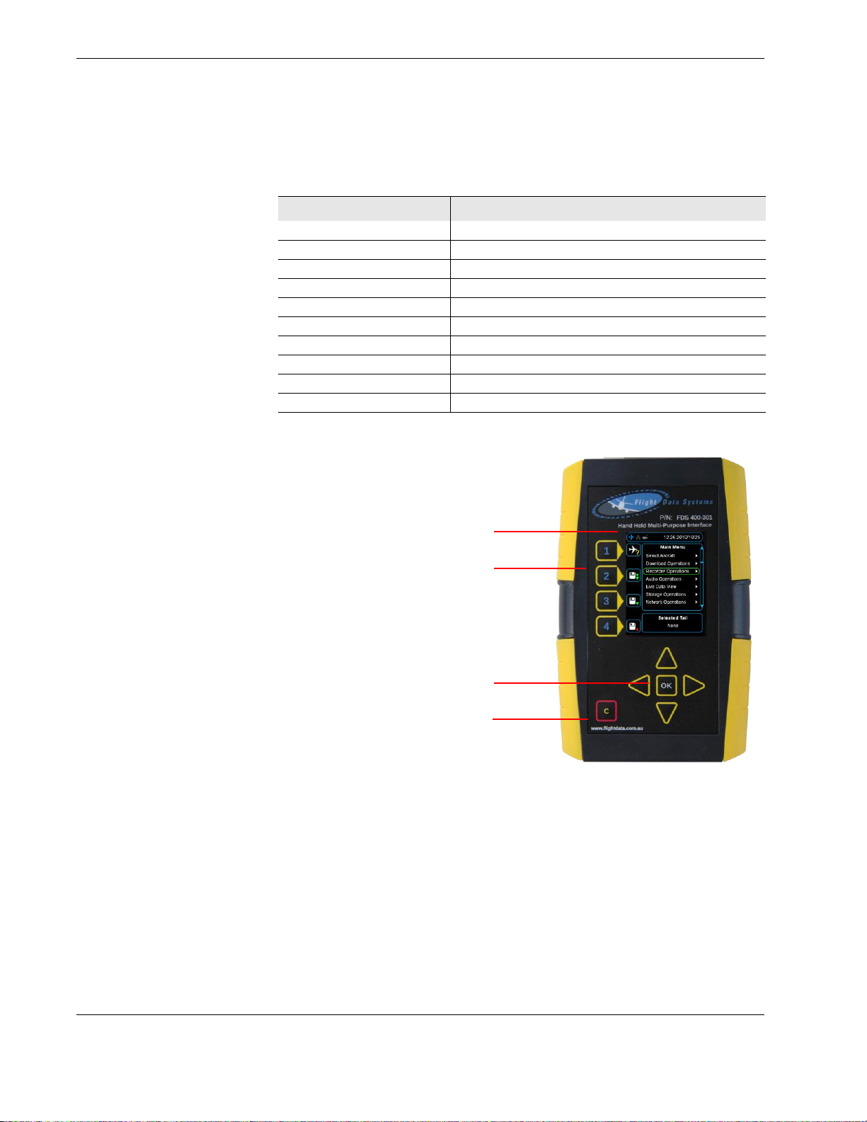
Legend
External devices connected:
recorder, external memory device,
Ethernet, USB flash drive
1.
User programmable shortcut keys
(4)
2.
OK button and cursor keys (4) 3.
Cancel / exit 4.
2.1 HHMPI models
Table 2.0 HHMPI models and description of modifications applied
HHMPI modifications Description
Mod 1 External battery with PCMCIA card slot
Mod 2 Firmware enhancement FA2100 CVR software (ADF)
Mod 3 VADR software interface implemented (ADF)
Mod 4 MCR500 software interface implemented (ADF)
Mod 5 Version 2 HHMPI
Mod 6 Internal battery on HHMPI added
Mod 7 Docking cradle
Mod 8 Audio jack added for CVR capability (ADF)
Mod 9 New revision firmware added (ADF)
Mod 10 New revision firmware added (ADF)
Figure 1.0 HHMPI front view
6 Operators manual
Handheld Multi-Purpose Interface (HHMPI)
Page 7
Introduction
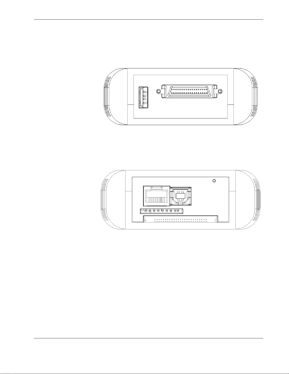
Figure 2.0 HHMPI top view
Figure 3.0 HHMPI bottom view
Operators manual 7
FDS 400-301
Page 8
Introduction
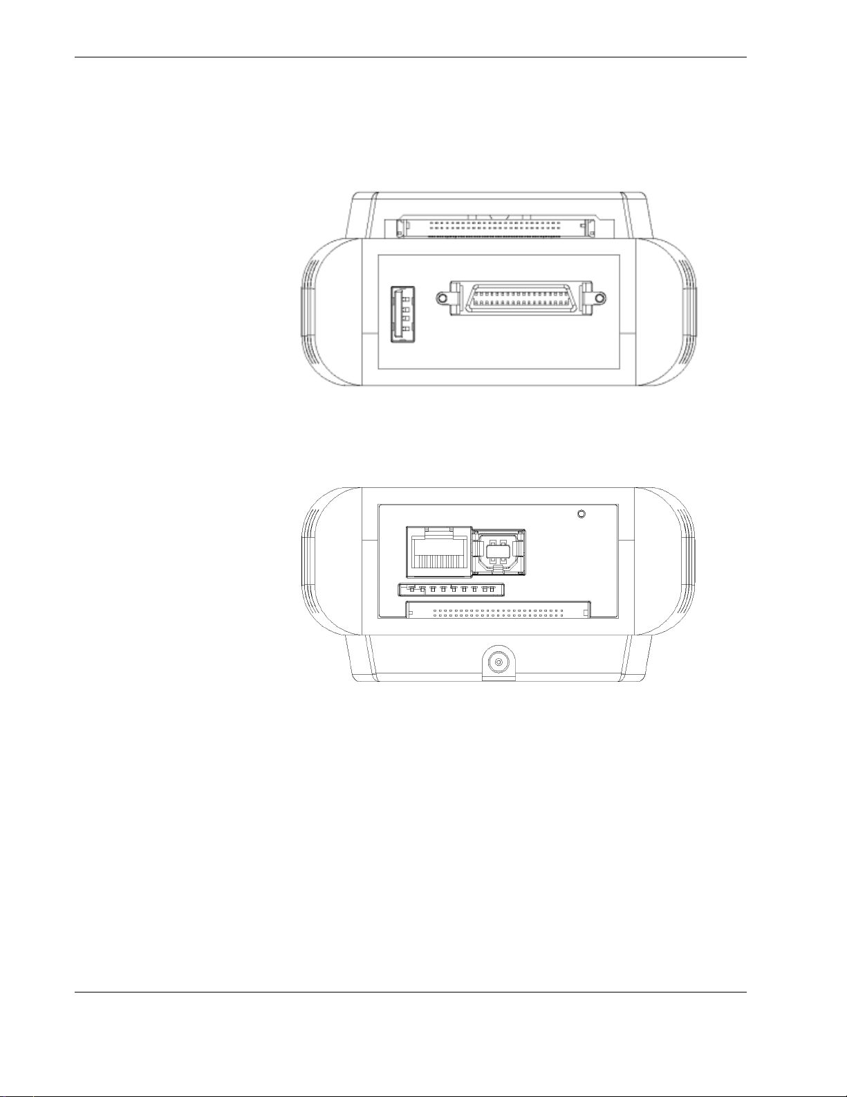
Figure 4.0 HHMPI Mod 1 top view
Figure 5.0 HHMPI Mod 1 bottom view
8 Operators manual
Handheld Multi-Purpose Interface (HHMPI)
Page 9
Introduction
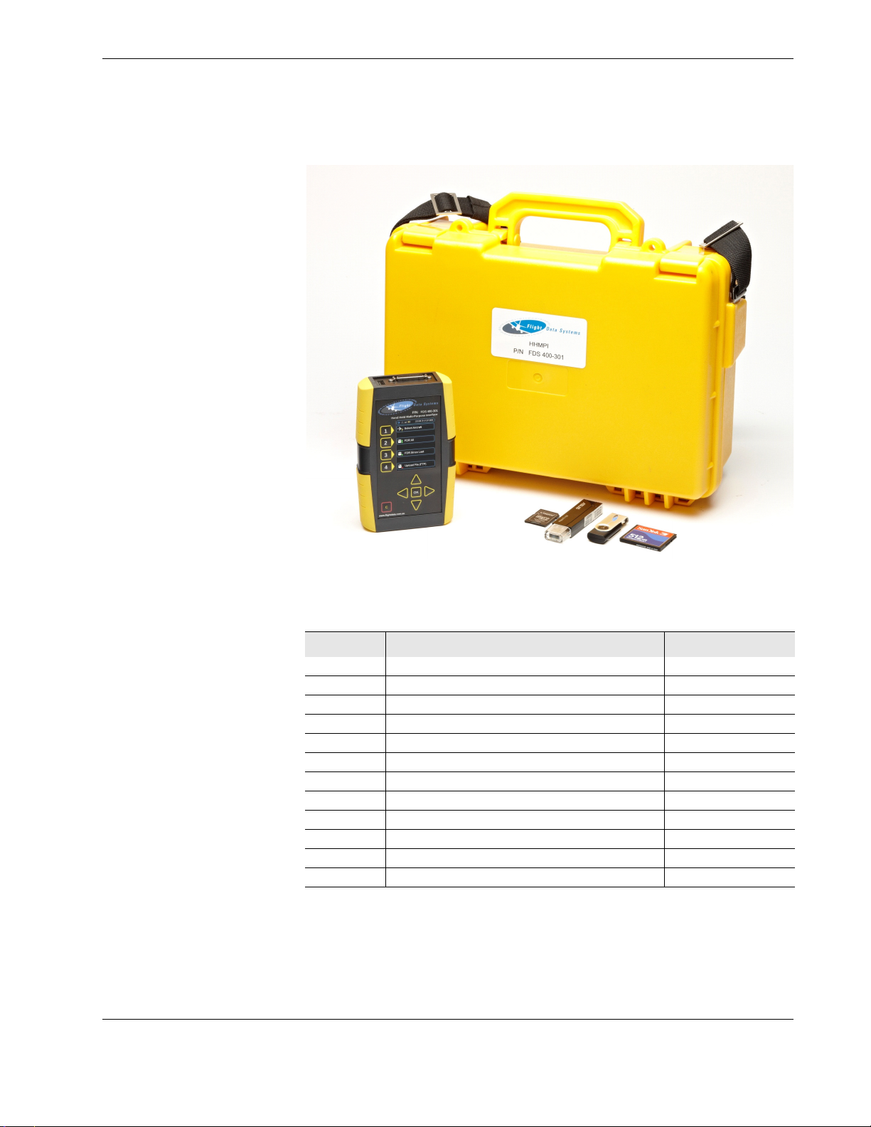
Figure 6.0 HHMPI kit
2.2 HHMPI equipment
Table 3.0 HHMPI equipment list
Part number Description Applicable mod status
DF136 Quick reference guide, HHMPI All
FDS400-107 Cable USB, HHMPI to PC All
FDS400-301 HHMPI Mod 5
FDS400-301 HHMPI with internal battery Mod 5, 6
FDS400-301 HHMPI with external battery and PCMCIA card Mod 1, 5
FDS400-302 USB flash drive (2GB) All
FDS400-303 Compact flash card, HHMPI Option - all
FDS400-304 SD card, HHMPI Option - all
FDS400-321 Carry case, yellow All except Mod 1
FDS400-322 Power adapter kit, global, charger for internal battery Mod 6
FDS400-334 Carry case, black Mod 1
FDS400-373 Docking cradle Mod 7
Operators manual 9
FDS 400-301
Page 10

Introduction
2.3 Accessories
Table 4.0 Interface cables and software options
Accessory part number Description
FDS400-107 Cable USB, HHMPI to PC
FDS400-201 Interface cable, L-3 AR, F1000
FDS400-202 Interface cable, L-3 AR, FA2100
FDS400-203 Interface cable, HNY, SSFDR, (DC or Battery HHMPI only)
FDS400-204 Interface cable, HNY, UFDR, SSDFDR
FDS400-208 Interface cable, HNY, AR series
FDS400-209 Interface cable, L-3 EDI, SRVIVR™
FDS400-210 Interface cable, HNY, Light weight
FDS400-212 Interface cable, MCR500
FDS400-215 Interface cable, SSCVR, Rack adapter and aircraft
FDS400-216 Interface cable, HYN, SSCVR, Bench download cable
FDS400-223 Interface cable, L-3 AR, FA5000/FA5001
FDS400-224 Interface cable, UASC, CVFDR, CVR, FDR
FDS400-227 Interface cable, HNY, DVDR
FDS400-232 Interface cable, HNY, HFR5-D
FDS400-246 Interface cable, HNY, AR CVR/Combi
FDS400-241 Interface cable, L-3 Micro QAR
FDS400-257 Interface cable adapter, MCR500 to SCR500
FDS400-258 Audio breakout fixture, MCR500 to SCR500
FDS400-259 Audio test fixture, SCR500
FDS400-331 Card reader, PCMCIA, option
FDS400-332 Wireless interface, USB 802.11g, option
FDS400-379 L-3 FA2100 CVR download and decompression software
FDS400-380 HNY CVR download and decompression software
2.4 Specifications
Table 5.0 Specifications HHMPI Mod 5 (no battery)
Parameter
Weight HHMPI: 330 g
Dimensions: L x W
x H
Power USB or FDR/CVR inter fa ce cable
Environmental
protection
Temperature Operating: -20°C to +60°C
HHMPI kit: 3 kg (see Figure 6.0, ”HHMPI kit”, on page 9)
Shipping: 4 kg
HHMPI: 145 x 95 x 35 mm
HHMPI kit: 365 x 270 x 135 mm
IP-40
10 Operators manual
Handheld Multi-Purpose Interface (HHMPI)
Page 11

Introduction
Table 5.0 Specifications HHMPI Mod 5 (no battery)
Parameter
Certification FCC Part 15 Subpart B, July 2008
Data view ARINC 717 for all recorders
Data view formats Binary
Memory supported
Communications USB v2.0 to PC
CE
ANSI C63.4-2003 EN55022: 2006 (CISPR22: 2005, modified)
AS/NZS CISPR22: 2006 (CISPR22: 2006)
EN55024: 1998 Amendment 1: 2001 Amendment 2: 2003
CISPR24: 1997 MODIFIED Amendment 1: 2001 Amendment 2: 2002
ARINC 429 standard
ARINC 429 periodic
Data Link Rate (DLR)
Octal
Decimal
Hexadecimal
Internal
SD card
CF card
USB flash drive
Ethernet RJ-45 to network
Ethernet via recorder interface to recorder
R2-422 via recorder interface to recorder
Wireless 802.11g capability via optional USB key
Table 6.0 Specifications HHMPI Mod 1 and 5 (battery)
Parameter
Weight HHMPI: 495 g
Dimensions: L x W
x H
Power USB or FDR/CVR inter fa ce cable
Environmental
protection
Temperature Operating: 0°C to +60°C
Certification FCC Part 15 Subpart B, July 2008
Data view ARINC 717 for all recorders
Data view formats Binary
HHMPI kit: 3.2 kg see (Figure 6.0, ”HHMPI kit”, on page 9)
Shipping: 4.2 kg
HHMPI: 145 x 95 x 46 mm
HHMPI kit: 365 x 270 x 135 mm
Internal Lithium Ion battery
IP-40
CE
ANSI C63.4-2003 EN55022: 2006 (CISPR22: 2005, modified)
AS/NZS CISPR22: 2006 (CISPR22: 2006)
EN55024: 1998 Amendment 1: 2001 Amendment 2: 2003
CISPR24: 1997 MODIFIED Amendment 1: 2001 Amendment 2: 2002
ARINC 429 standard
ARINC 429 periodic
Data Link Rate (DLR)
Octal
Decimal
Hexadecimal
Operators manual 11
FDS 400-301
Page 12
Getting started
Table 6.0 Specifications HHMPI Mod 1 and 5 (battery)
Parameter
Memory supported
Communications USB v2.0 to PC
Internal
SD card
CF card
USB flash drive
PCMCIA card (ATA flash type only)
Ethernet RJ-45 to network
Ethernet via recorder interface to recorder
R2-422 via recorder interface to recorder
Wireless 802.11g capability via optional USB key
3.0 Getting started
3.1 Terminology used in this manual
In this manual the hardware buttons on the HHMPI are referred to as the left, right, up,
down, OK, or cancel buttons. See Figure 1.0, ”HHMPI front view”, on page 6 for the loca-
tions of these buttons on the HHMPI.
In this manual you may also see information of special importance in the form of tips and
notes.
A note with the heading “Note” indicates neutral or positive information that emphasizes
or supplements important points in this manual. For example:
Note If the HHMPI prompts you for a network password at startup,
your FTP network is already set up, and you can skip this section.
A tip is a type of note that helps you apply the techniques and procedures described in
this manual. A tip may suggests an alternative method of completing a task—tips are not
essential to the basic understanding of this manual. For example:
Tip You can also use these steps to copy an aircraft definition file.
An important note provides information that is essential to the completion of a task. You
can disregard information in a note and still complete a task, but you should not disre-
gard an important note. For example:
Important When powering up the HHMPI ensure that no external
devices are connected.
12 Operators manual
Handheld Multi-Purpose Interface (HHMPI)
Page 13

Getting started
A caution is a type of note that advises you that failure to take or avoid a specific action
could result in damage or loss of data. For example:
Caution Before applying power, verify that the product is set to
match the line voltage and the correct fuses are installed.
A menu sequence shows you how to open a series of menus. For example:
▼▲
Main Menu >Device Configuration > Settings Profile > Save Aircraft >
USB Flash Drive
3.2 Using the HHMPI To download data from a Flight Data Recorder (FDR) or Cockpit Voice Recorder (CVR), you
need the following equipment:
The HHMPI kit, see Figure 6.0, ”HHMPI kit”, on page 9.
An interface cable for the specific recorder you want to download data from, see
Table 4.0, “Interface cables and software options,” on page 10.
3.2.1 Connecting the HHMPI to an FDR
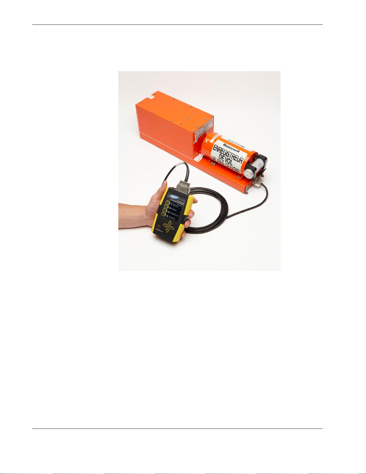
To connect the HHMPI to a recorder use the interface cable for the specific recorder you
want to download data from. Power is often supplied through the interface cable to the
HMMPI from an aircraft powered recorder. In this configuration it is safe to connect or
disconnect the HHMPI. See Figure 7.0, ”Connecting the HHMPI to the FDR or CVR”, on
page 14.
Operators manual 13
FDS 400-301
Page 14
Getting started
Figure 7.0 Connecting the HHMPI to the FDR or CVR
3.2.2 Powering and charging the HHMPI
The HHMPI can be powered by:
An aircraft powered recorder through an interface cable.
A PC or USB adapter power though a USB cable (P/N: FDS400-107).
The internal battery, on battery equipped HHMPI devices.
The external battery, on Mod 2 HHMPI devices.
▼▲
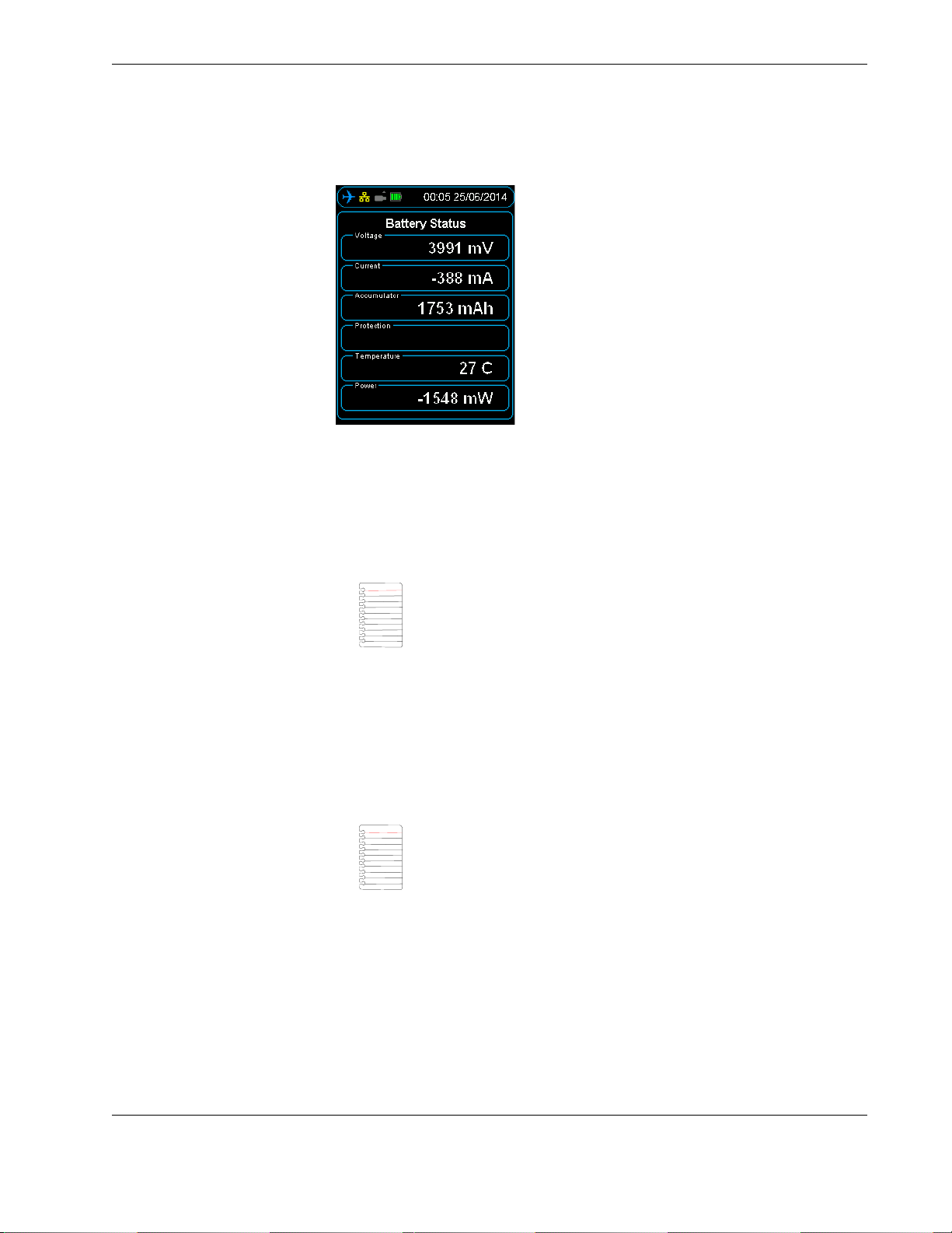
To m o ni t or b a t t er y s tat u s:
Press right to open the Main Menu.
Scroll down to Battery Status and press OK.
See Figure 8.0, ”The Battery Status screen”, on page 15.
Main Menu > Battery Status
14 Operators manual
Handheld Multi-Purpose Interface (HHMPI)
Page 15
Getting started
Figure 8.0 The Battery Status screen
Battery powered HHMPI devices can be charged with:
An aircraft powered recorder through an interface cable.
A PC or USB adapter power though a USB cable (P/N: FDS400-107).
A global power adapter kit (P/N: FDS400-322).
Note External battery powered HHMPI devices can only be charged
with the external battery pack charge cable (P/N: FDS400-335).
Charge battery powered HHMPI devices for 12 hours before first use. Charging is indicated by a blue battery icon found in the status bar of the display. Full charge is indicated
by a green four bar battery icon. When charging is required, this battery icon turns red.
You can use the HHMPI when it is charging, however this increases the charging time.
3.2.3 Charging the HHMPI with the docking cradle
Note Only applicable to HHMPI devices with Mod 7.
HHMPI devices with Mod 7 can also be charged by a power adapter through the HHMPI
docking cradle (P/N: FDS400-373).
To charge the HHMPI with the docking cradle:
1. Connect the power adapter to the docking cradle, the green light will illuminate.
2. Insert the HHMPI into the docking cradle, the HHMPI will beep and go through the
start-up process, and then begin charging.
See Section 3.2.2, ”Powering and charging the HHMPI” on page 14 for charging indi-
cators.
Operators manual 15
FDS 400-301
Page 16
Getting started
Flight Data Systems recommends using the HHMPI Cradle for the following reasons:
The cradle provides direct current (DC) charging which extends battery life by avoid-
ing trickle charging.
The transfer of files from the HHMPI to the PC is stable and easy to operate when
docked.
Auto-sync and transfer files from the unit to a nominated FTP server via Ethernet con-
nection.
Configure the unit in the web interface using the Ethernet connection on the cradle.
3.2.4 Turning on the HHMPI and self-test
Important When powering up the HHMPI ensure that no external
devices are connected.
To turn on a battery powered HHMPI, press cancel or OK for 2–3 seconds until the unit
beeps.
Once turned on, the start-up process begins and the power-on self-test is carried out. If
connected, the interface cable is detected automatically, and correct connection to the
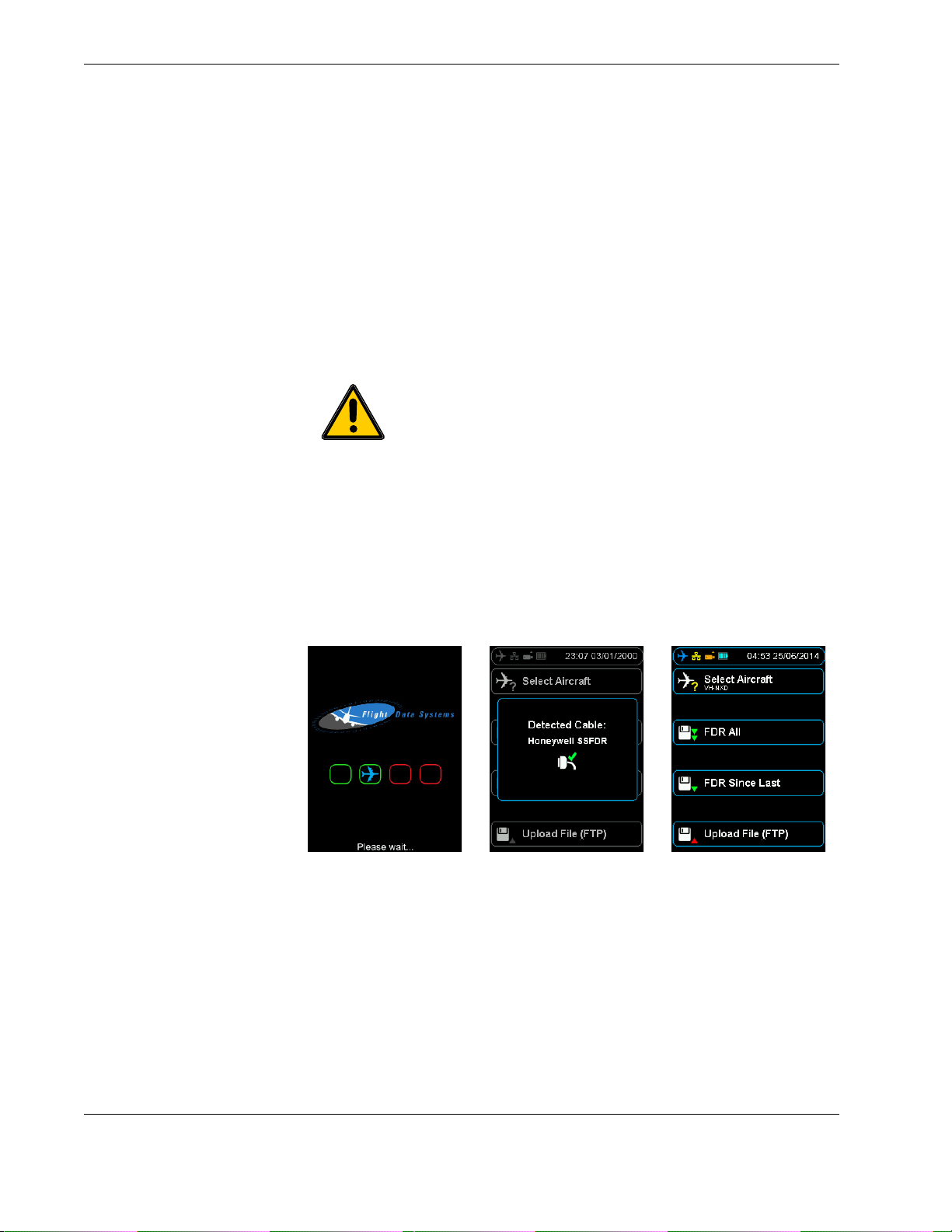
flight data recorder is indicated by a blue aircraft icon found in the status bar of the display. See Figure 9.0, ”HHMPI power-on sequence”, on page 16.
Figure 9.0 HHMPI power-on sequence
To turn off the HHMPI, press cancel until the Confirm Power Off alert is displayed, and
then press OK to confirm.
3.2.5 Reset operation
If the HHMPI does not respond to normal key operation, a warm reset may be carried out
by pressing the reset button for five seconds. This will reboot the HHMPI and return it to
the shortcut screen. See Figure 3.0, ”HHMPI bottom view”, on page 7 for the location of
the reset button.
16 Operators manual
Handheld Multi-Purpose Interface (HHMPI)
Page 17

Getting started
3.3 Shortcuts Shortcuts are used to provide user’s with a quick path to commonly used functions. There
are four user defined shortcuts buttons.
▼▲
The HHMPI displays the shortcut keys following the start-up and self-test. The shortcut
keys default to the following functions:
Select Aircraft
FDR All
FDR Since Last
Upload File (FTP)
Main Menu > Device Configuration > Shortcut Keys > Shortcut n
3.4 Menu structure The HHMPI is controlled by a menu system. The four arrow buttons are used to navigate
the menu system. Generally, the right button is used to enter menus and the OK button
is used to confirm selections.
Note The menu options may change depending on the type of
recorder or other devices attached.
Tip To return to the Main menu from any other menu, press left
repeatedly.
3.5 HHMPI configuration
The HHMPI can be configured via a web interface, or directly on the unit. Using the web
interface is the easiest way to set up the HHMPI, see Section 5.4.1, ”Changing the HHMPI
configuration via the web interface” on page 39.
3.5.1 Clock Settings
▼▲
Set the date and time format.
Main Menu > Device Configuration > Clock Settings
3.5.2 Display Settings
▼▲
Set the brightness of the display, 1 is minimum brightness and 10 is maximum brightness.
Main Menu > Device Configuration > Display Settings
3.5.3 Memory Settings
▼▲
Set the preferred memory to download or file transfer by selecting one of the following:
Operators manual 17
FDS 400-301
Main Menu > Device Configuration > Memory Settings
Page 18

Getting started
Ask for device - Prompts the user to specify a device for download or file transfer.
Priority list - Prioritize memory devices based on customised preference.
User Specified Device - Set default memory device for storage and file transfer.
3.5.4 Network Settings
▼▲
Main Menu > Device Configuration > Network Settings
When connecting the HHMPI to a network connection via an Ethernet cable, setup IP,
DHCP and FTP settings necessary for network operation. See Section 4.7, ”Network oper-
ations” on page 33.
3.5.5 Aircraft Settings
▼▲
Set or edit aircraft tail numbers. See Section 4.2, ”Aircraft lists” on page 19.
Main Menu > Device Configuration > Aircraft Settings
3.5.6 Security Settings
▼▲
Set access to the menus and settings of the HHMPI by using password access by selecting the following:
Restrict Configuration - Restrict modification of any HHMPI settings.
Restrict Menus - Only allow access to previously configured shortcut keys.
Main Menu > Device Configuration > Security Settings
3.5.7 Live Data Settings
▼▲
Main Menu > Device Configuration > Live Data Settings
Set the global live data settings to be used in the live data view from, some of these
options may only be available for the L-3 Communications SRVIVR™™ interface:
ARINC 717
ARINC 429. Standard or periodic.
DLR Settings. Select the data display format and data word description.
3.5.8 Shortcut Keys
▼▲
Set shortcut keys to change by selecting one of the options from the menu.
Main Menu > Device Configuration > Shortcut Keys
3.5.9 Settings Profile
▼▲
Save or load the device configuration to a file, or reset the configuration to the factory
default settings:
Main Menu > Device Configuration > Settings Profile
18 Operators manual
Handheld Multi-Purpose Interface (HHMPI)
Page 19

Operation
Load Settings
Save Settings
Reset Configuration
3.6 Information All the information about the HHMPIs feature set, supported recorder types and the
operating system version is found in the Information menu. This information may be useful for troubleshooting, see Section 7.0, ”Troubleshooting” on page 44.
4.1 Download file name
▼▲
To access the HHMPI information, from the Main Menu press down until you reach the
Information command, and then press OK. The information in the Asset., Company and
Contact fields can be changed via the web interface, see Section 5.4.1, ”Changing the
HHMPI configuration via the web interface” on page 39. The remaining fields are only
configurable by Flight Data Systems.
Main Menu > Information
4.0 Operation
Files downloaded from a recorder to the HHMPI follow a standard naming convention,
configured by the Filename Style command on the Settings menu. The naming conven-
tion is: _[aircraft tail number]_[date[_time]]_download type.ext
For example:
_20101010_1204_FDR_5_MINUTES.fdr
_VHFDS_101_20101010_1204_FDR_ALL.dlu
_VHFDS_101_20101010_1204_CVR_ALL.cvr
Note The file extension can vary according to the recorder type and
download mode.
The date and time string use the time format already configured in
the HHMPI.
Special characters within the aircraft tail numbers are automatically
converted to underscores “_”.
Dates and time stamps are stripped to remove slashes and colons.
4.2 Aircraft lists Stored in the HHMPI as a comma separated variable file, the Aircraft List contains a list of
all aircraft in the fleet. Using an Aircraft List makes it easier to assign tail numbers to
operational downloads, it also makes the file names more readable.
4.2.1 Loading aircraft details
The Aircraft List may be created and stored in a HHMPI to populate the aircraft tail variable in the data file name. When an Aircraft List is not present, data file names will default
to _[aircraft tail number]_[date[_time]]_download type.ext. See Section 4.1, ”Download file
name” on page 19.
Operators manual 19
FDS 400-301
Page 20
Operation
4.2.2 Creating an Aircraft List on a PC
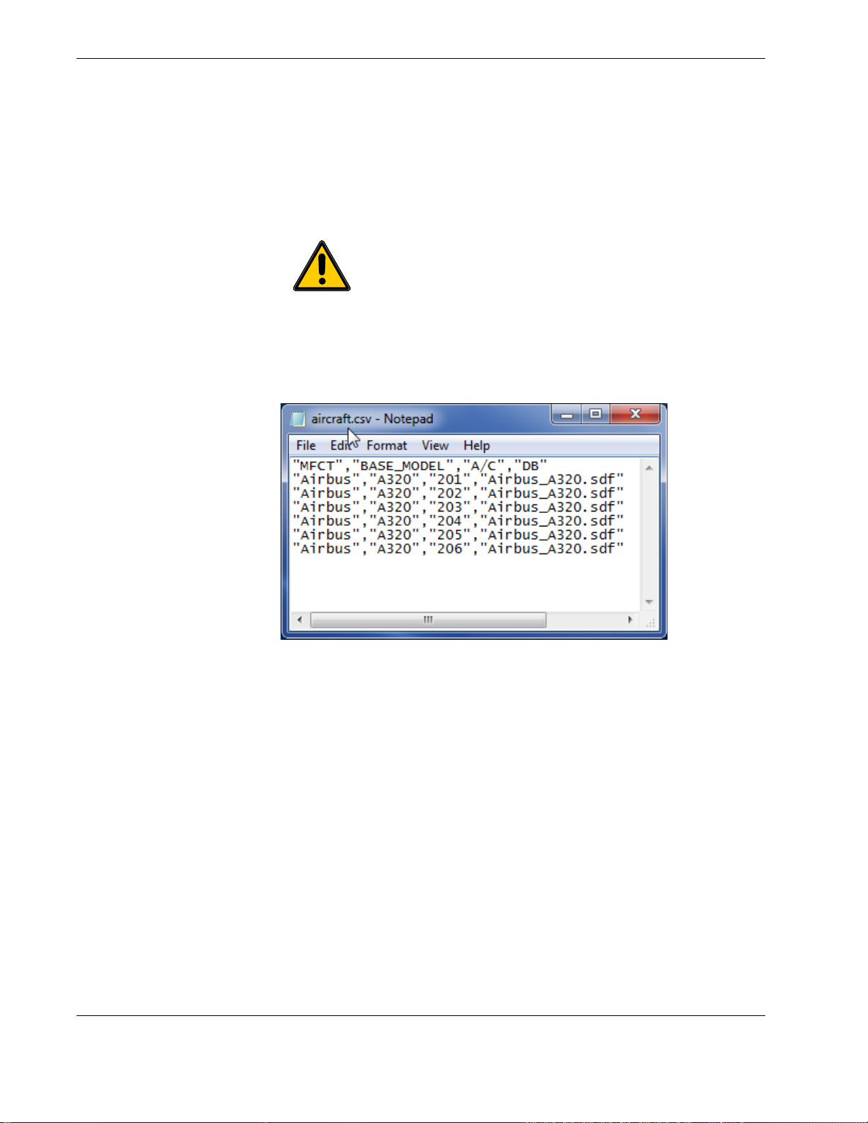
The Aircraft List can be created on a PC using a text editor, such as Notepad, or in a
Spreadsheet application, such as Excel, and exported as comma separated variable (.csv)
file. Figure 10.0, ”Creating an Aircraft List in Notepad”, on page 20.
Important The file must be named aircraft.csv and the data fields
must be separated by a comma with each record separated by a carriage return (ASCII CR-LF).
Although not shown to the operator, the manufacturer field (MFCT)
must also be present. However, the aircraft definition filed (DB) is
only required for the Engineering Units (EU) function, see Section 4.5,
”Viewing live flight data in engineering units” on page 29.
Figure 10.0 Creating an Aircraft List in Notepad
Save or export the file to a USB flash drive as aircraft.csv. If an Aircraft List is not present,
data file names will default to _[aircraft tail number]_[date[_time]]_download type.ext.
4.2.3 Transferring the Aircraft List to the HHMPI
▼▲
To transfer the Aircraft List to the HHMPI, insert the USB flash drive containing the file
named aircraft.csv into the USB port on top of the HHMPI.
1. From the Main Menu, press down until you reach the Device Configuration com-
mand, and then press right.
2. Press down until you reach the Settings Profile command, and then press right.
3. Press down until you reach the Load Aircraft command, and then press right.
4. Select where the file named aircraft.csv is located, and then press right.
Main Menu > Device Configuration > Settings Profile > Load Aircraft
20 Operators manual
Handheld Multi-Purpose Interface (HHMPI)
Page 21
Operation
4.2.4 Creating the Aircraft List on the HHMPI
▼▲
Main Menu > Device Configuration > Aircraft Settings > Add Aircraft
Tip For a large amount of aircraft, consider importing an Aircraft List
as a comma separated variable file (aircraft.csv). See Section 4.2.2, ”Cre-
ating an Aircraft List on a PC” on page 20.
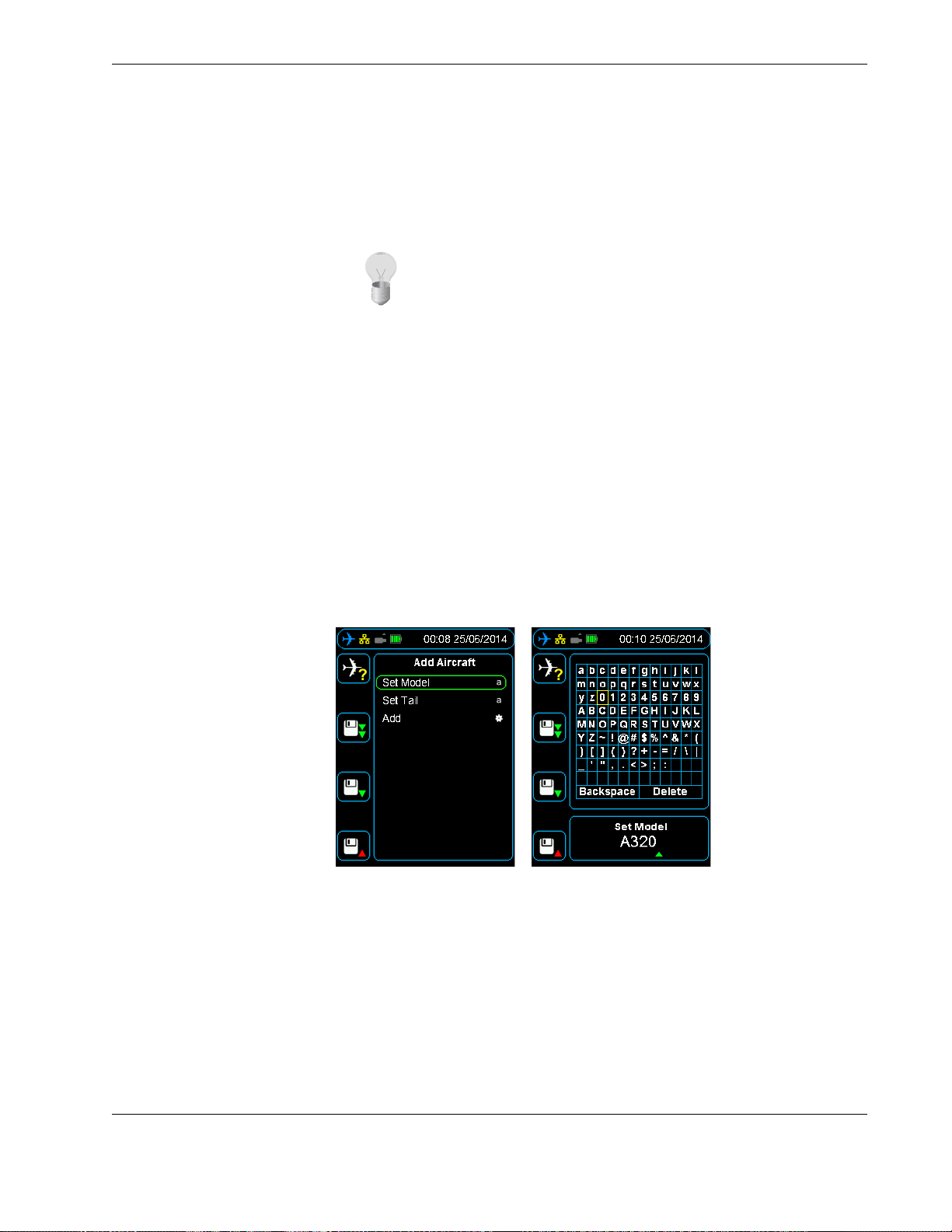
To create, or add to, the Aircraft List on the HHMPI, from the Add Aircraft menu:
1. Press down until you reach the Set Model command, and then press right.
2. Press up to enter the alphabetical grid, and then press the up, down, left and right
buttons to enter data.
3. When complete, press cancel to exit the alphabetical grid.
4. Press OK to confirm your selection.
5. Repeat steps 1 to 4 for Set Tail.
6. Press down until you reach the Add command, and then press right to confirm.
7. Press OK to confirm your selection.
To add additional aircraft, repeat steps 1 to 6 for each aircraft. See Section Figure 11.0,
”Adding aircraft to the Aircraft List on the HHMPI” on page 21.
Figure 11.0 Adding aircraft to the Aircraft List on the HHMPI
4.2.5 Adding Entries to the HHMPI Aircraft File
See Section 4.2.4, ”Creating the Aircraft List on the HHMPI” on page 21.
4.2.6 Deleting an aircraft from the Aircraft list on the HHMPI
▼▲
To delete an aircraft from the Aircraft list on the HHMPI, from the Device Configuration
menu:
Operators manual 21
FDS 400-301
Main Menu > Device Configuration > Aircraft Settings > Delete Aircraft
Page 22

Operation
1. Press down until you reach the Aircraft Settings command, and then press right.
2. Press down until you reach the Delete Aircraft command, and then press right to
select the aircraft you want to delete.
3. Press OK to confirm the deletion.
Selected aircraft remain in the list but are marked by a red X.
4.2.7 Saving the Aircraft list to the USB flash drive on the HHMPI
▼▲
Main Menu > Device Configuration > Settings Profile > Save Aircraft
To save the Aircraft List to a USB flash drive, insert a USB flash drive into the USB port on
the top of the HHMPI, and from the Device Configuration menu:
1. Press down until you reach the Settings Profile command, and then press right.
2. Press down until you reach the Save Aircraft command, and then press right to save
onto USB Flash Drive.
Important The Aircraft List is saved to the USB flash drive as air-
craft.csv.bkp. To transfer this file to the HHMPI again, it must be
renamed aircraft.csv.
Tip The saved aircraft.csv file can be used as a template to add more
aircraft or aircraft definition f iles (databases) to the Aircraft List.
4.2.8 Deleting all aircraft from the Aircraft list on the HHMPI
▼▲
Main Menu > Device Configuration > Aircraft Settings > Erase All Aircraft
By selecting this option all the aircraft models and tail numbers in the Aircraft List will be
removed from the HHMPI. Press OK to confirm or cancel to cancel this operation.
4.2.9 Prompt for Tail No.
▼▲
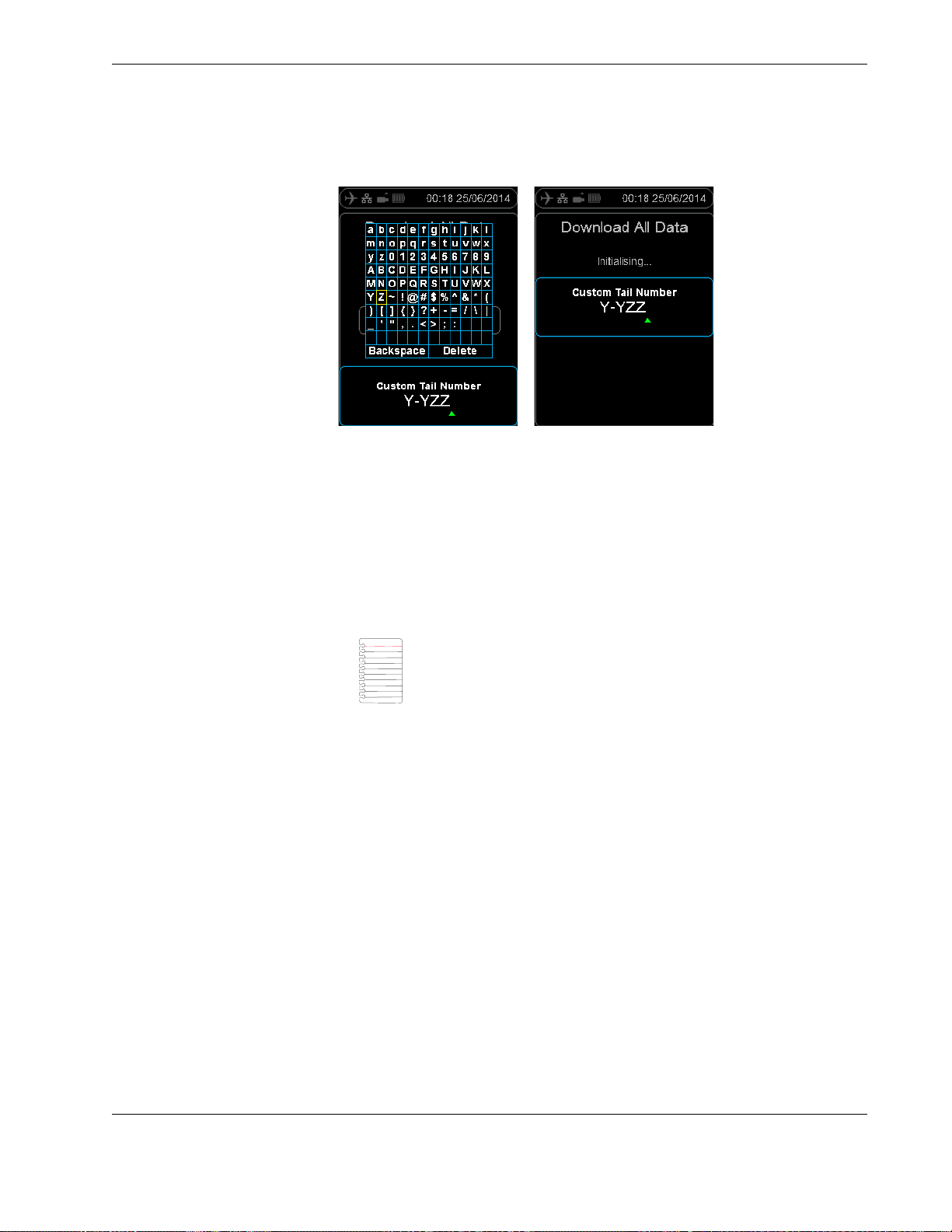
Enabling the Prompt for Tail No. command forces a user to assign a tail number to an
operational download. This ensures that a download file name contains the aircraft tail
number, which may help in traceability of data and further analysis.
Main Menu > Device Configuration > Aircraft Settings > Prompt for Tail
No.
22 Operators manual
Handheld Multi-Purpose Interface (HHMPI)
Page 23
Operation
Figure 12.0 Configuring the prompt for tail number option
4.3 Downloading flight data
The HHMPI can be used to download recorded data from the FDR and voice from the
CVR. It is connected to the recorder via an interface cable which identifies the attached
recorder type. When downloading flight data, the following procedure is generally used:
Create the Aircraft List, if required. See Section 4.2, ”Aircraft lists” on page 19. The Air-
craft List may be created and stored in a HHMPI to populate the aircraft tail variable
in the data file name. The manufacturer and model variables are not used in the data
file name.
Select the aircraft, model and tail number from the Aircraft List.
Note If this step is omitted the file name will only include the time
stamp. If you want to force users to assign a tail number before an
operational download enable the Prompt for Tail No. command.
See Section 4.2.9, ”Prompt for Tail No.” on page 22.
Start downloading flight data as follows.
4.3.1 Downloading recorded data from the FDR to a USB flash drive
To download flight data from the FDR to a USB flash drive:
1. Connect the HHMPI to the FDR with an interface cable, see Figure 7.0, ”Connecting
the HHMPI to the FDR or CVR”, on page 14.
2. Turn on the HHMPI and FDR. Once turned on, the start-up process begins and the
power-on self-test is carried out. If connected to the HHMPI, the interface cable is
detected automatically, and correct connection to the FDR is indicated by a blue aircraft icon found in the status bar of the display.
3. Plug the USB flash drive into the USB port on the top of the HHMPI. An alert, USB
Drive Inserted, should appear monetarily.
An orange USB flash drive icon will also appear in the status bar indicating the HHMPI
is ready to write to the USB flash drive.
▼▲
4. From the Main Menu, press down until you reach the Download Operations com-
mand, and then press right. Then press down until you reach the data you want to
Main Menu > Download Operations
Operators manual 23
FDS 400-301
Page 24
Operation
download, and then press right. There is usually four download commands, depending on the type of recorder:
FDR All, downloads all the available data.
FDR Since Last, downloads all the data recorded since the last download.
FDR Mark, downloads the data from a pre-recorded marker.
FDR Time, downloads data for a specified time, for example, 20 minutes will
download the last 20 minutes recorded.
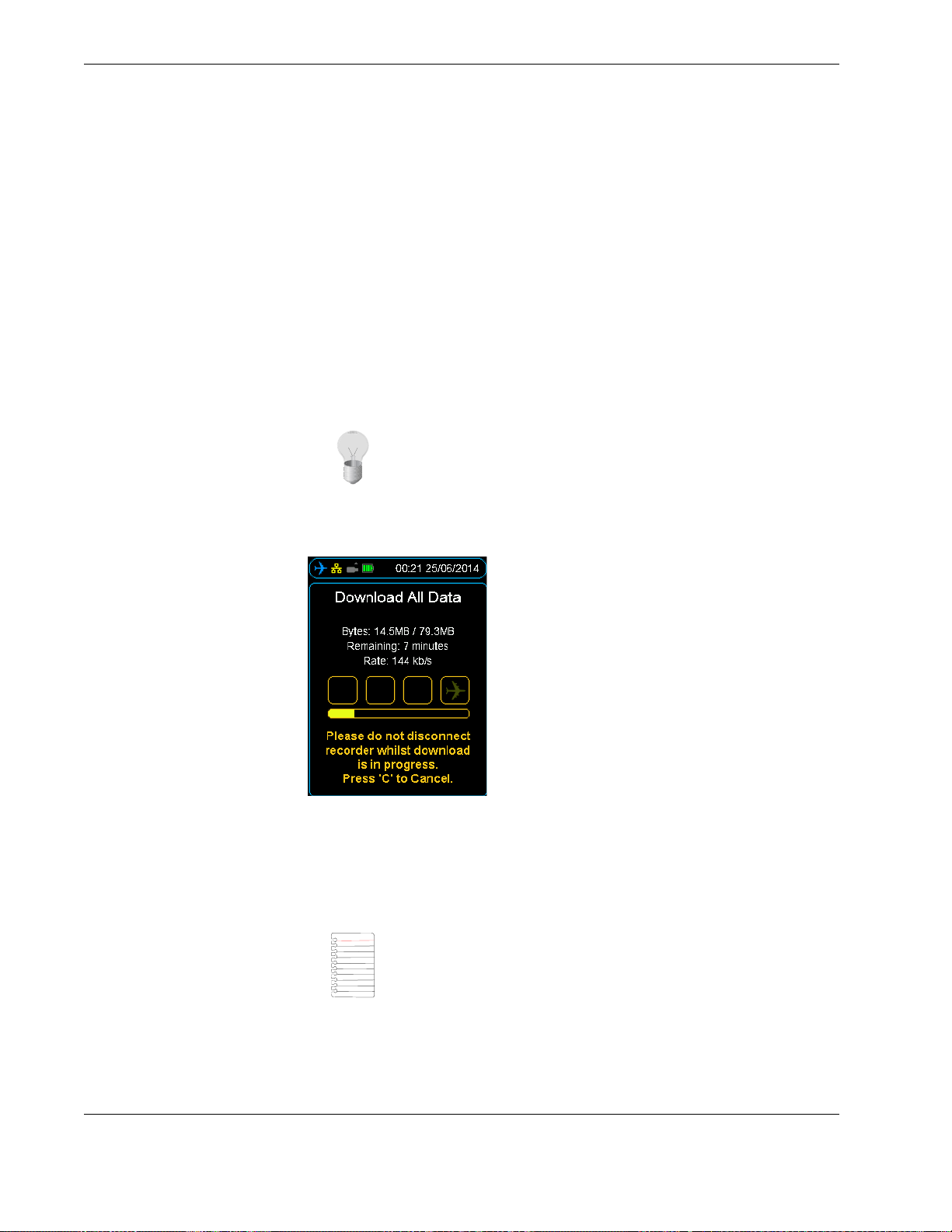
5. If an external storage device, like a USB flash drive, is plugged into the HHMPI, you
may now select to store the data onto this device. To start downloading the data,
press right.
The display will now show the download progress. When the download completes,
press OK.
Tip You can set the preference of external storage devices from the
Memory Settings menu. For example, prioritise the USB flash drive,
when present, over the HMMPI internal memory.
Figure 13.0 Downloading progress bar
4.3.2 Decompressing CVR data at the aircraft
To play CVR files on a computer or another device, you may need to decompress the raw
file into a waveform file (.wav). See Section 4.3, ”Downloading flight data” on page 23.
Note To decompress CVR data at the aircraft, the de-multiplexing
feature needs to be enabled on the HHMPI. Contact Flight Data Systems for more information about this feature.
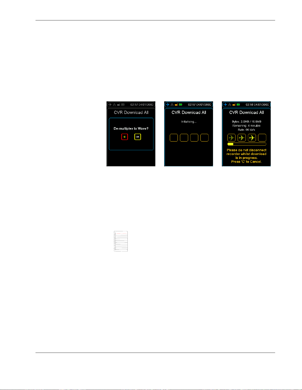
After selecting CVR download, the De-multiplex to Wave option will appear. Press the
OK button to decompress the raw CVR file to waveform files. Generally there will a waveform for each channel recorded on the CVR. If you do not want to decompress the raw
24 Operators manual
Handheld Multi-Purpose Interface (HHMPI)
Page 25
Operation
CVR file to waveform files, press the cancel button. See Section Figure 14.0, ”Download-
ing and decompressing CVR data” on page 25.
After the download completes, the raw CVR file and the waveform files from each channel will be available on the nominated storage device. These files can be transferred to a
computer or another device where they can be replayed. A codec may need to be
installed, this is included as part of the HHMPI kit.
Figure 14.0 Downloading and decompressing CVR data
4.3.3 Decompressing CVR away from the aircraft
▼▲
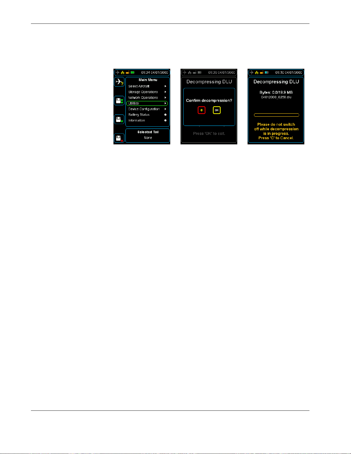
From the home screen, press right to access the Main Menu, scroll down to the Utilities
command, and then press OK.
On the Decompress DLU command, press OK, and then select the raw .dlu file to
decompress and the decompression process will begin.
Main Menu > Utilities > Decompress DLU
Note To decompress CVR data away from the aircraft, the de-multi-
plexing feature needs to be enabled on the HHMPI. Contact Flight
Data Systems for more information about this feature. Decompression of CVR data away from the aircraft also only applies to Honeywell CVRs.
Operators manual 25
FDS 400-301
Page 26
Operation
Figure 15.0 Decompressing Honeywell CVR file away from the aircraft
After the decompression completes, the raw CVR file and the waveform files from each
channel will be available on the nominated storage device. These files can be transferred
to a computer or another device where they can be replayed. A codec may need to be
installed, this is included as part of the HHMPI kit.
4.3.4 Using the CVR rack adapter
To download the CVR data, record mode must be disabled. Without disabling record
mode, you cannot download CVR data. Use the CVR rack adapter to power the CVR from
aircraft power by plugging it into aircraft power and then into the rear of the CVR. Once
powered, recording is disabled on the CVR and the data is ready to download.
4.4 Viewing live flight data
4.3.4.1 Using the Honeywell CVR Rack Adaptor part number FDS400-215
Firstly ensuring no power is provided to the CVR, disconnect the aircraft power from
the back of the Honeywell CVR while in the rack.
Connect the CVR Rack adaptor into the back of the CVR and reconnect aircraft power
to the CVR Rack adaptor instead.
Power the CVR at the aircraft and then connect the HHMPI interface cable (connected
to the Rack Adaptor) to the HHMPI and start up the unit.
With CVR recording now disabled using the Rack Adaptor ensure the blue plane
appears in the HHMPI and begin a CVR download at the aircraft.
4.3.4.2 Using the L-3 CVR Rack Adaptor part number FDS400-247
The L-3 CVR Rack Adaptor is almost the same design as the Honeywell. The difference
is it doesn't have nor require the Interface cable connection to the HHMPI.
Connect the L-3 CVR Rack Adaptor the same way as instructed with the Honeywell
CVR Rack Adaptor. Ensure Aircraft power is switched off to the CVR when plugging in
the adaptor to the CVR then the aircraft power connection.
Using the additional cable - The FA2100 Interface Cable P/N FDS400-202 insert this
into the CVR front GSE connector and then into the HHMPI. Power the CVR and
power the HHMPI. Ensure the blue plane appears in the HHMPI and begin a CVR
download at the aircraft.
The HHMPI can be used to monitor live ARINC 717 data from the aircraft. The Live Data
View can display data from the FDR in five formats:
26 Operators manual
Handheld Multi-Purpose Interface (HHMPI)
Page 27

Operation
Binary (Base 2)
Octal (Base 8)
Decimal (Base 10)
Hexadecimal (Base 16)
Engineering units (EU)
The Live Data View display options are accessible via the shortcut buttons 1–4.
Note These menu items will only be visible where they are supported
by the connected FDR/CVFDR.
To view live data from the FDR:
1. Connect the HHMPI to the FDR with an interface cable, see Figure 7.0, ”Connecting
the HHMPI to the FDR or CVR”, on page 14.
2. Turn on the HHMPI and the FDR. Once turned on, the start-up process begins and the
power-on self-test is carried out. If connected to the HHMPI, the interface cable is
detected automatically, and correct connection to the FDR is indicated by a blue air-
craft icon found in the status bar of the display.
▼▲
3. From the Main menu, press down until you reach the Live Data View command, and
Main Menu > Live Data View > View Live FDR Data > View ARINC 717
Data
then press right. Then press down until you reach the View Live FDR Data com-
mand, and then press right to View ARINC 717 Data. See Figure 16.0, ”Viewing live
data”, on page 27.
4. Wait until the HHMPI synchronizes with the FDR, while synchronizing, UNKNOWN is
displayed on the screen. After synchronizing, you can view live data from the aircraft
parameters.
For more information about formatting and displaying data on the HHMPI, see
Section 4.4.2, ”Adjusting ARINC 717 settings” on page 28 and Section 4.4.3, ”Changing the display format” on page 28.
Figure 16.0 Viewing live data
Operators manual 27
FDS 400-301
Page 28
Operation
4.4.1 Live Data View Options
Multiple ARINC 717 words can be displayed simultaneously, these words are selected
using the shortcut buttons 1 to 4.
4.4.2 Adjusting ARINC 717 settings
▼▲
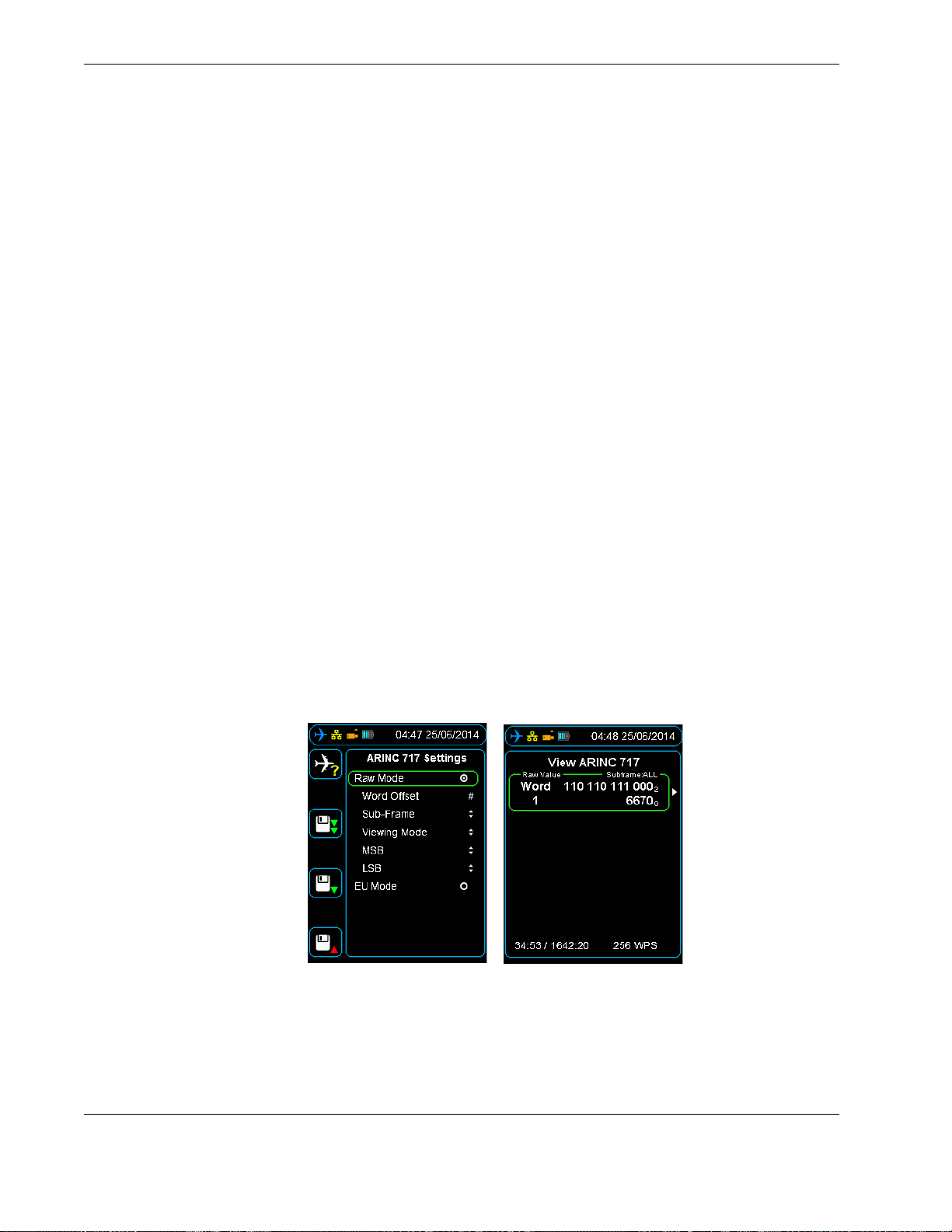
To access the ARINC 717 settings, press right on a selected parameter / word cell. The
following options will be displayed:
Word Offset, selects the current word from 1 to 2048. To change the Word Offset
number, use the up, down, left and right buttons, and then press OK to conf irm your
selection.
Sub-frame, selects the sub-frame to view from 1 to 4, or ALL. ALL is the default value
for this setting. To change the sub-frame, use the up and down buttons, and then
press right to confirm your selection.
Viewing Mode, provides the option to view live data in the following formats: Binary-
Octal, Binary-Decimal and Binary-Hexadecimal. To change the viewing mode, use the
up and down buttons, and then press right to confirm your selection.
MSB (Most Significant Bit), hides all binary bits in the word before the MSB. To
change the MSB, use the up and down buttons, and then press right to confirm your
selection.
LSB (Least Significant Bit), hides all binary bits in the word after the LSB. To change
the LSB, use the up and down buttons, and then press right to confirm your selection.
Main Menu > Live Data View > View Live FDR Data > View ARINC 717
Data
4.4.3 Changing the display format
Figure 17.0 ARINC 717 settings
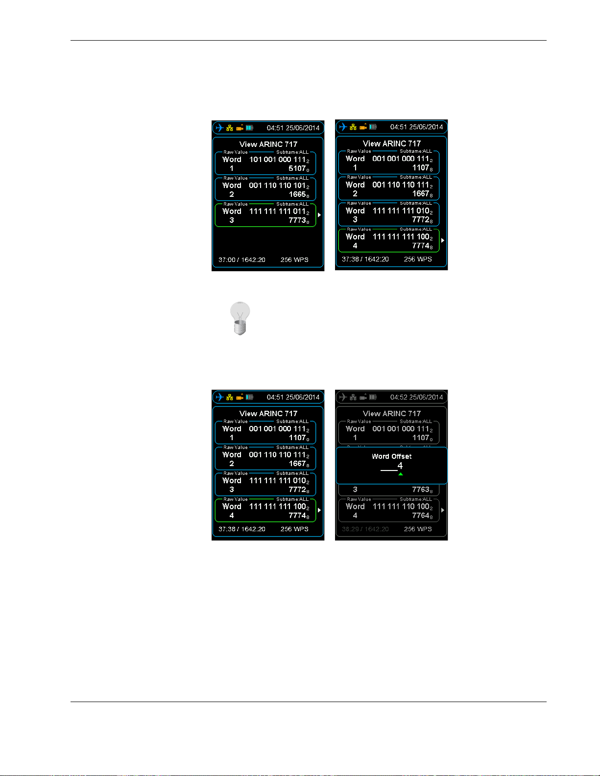
Simultaneous words can be displayed if required by using shortcut buttons 1 to 4. See
Figure 18.0, ”Multiple live data view”, on page 29.
Parameters for each displayed Live Data Word-Offset can be modified. See Section 4.4.3,
”Changing the display format” on page 28.
28 Operators manual
Handheld Multi-Purpose Interface (HHMPI)
Page 29
Operation
Figure 18.0 Multiple live data view
Tip Word Offset can be adjusted by the following:
Main Menu > Live Data View > View Live FDR Data > View ARINC 717
Data > Up | Down | Left | Right
4.5 Viewing live flight data in engineering units
Figure 19.0 Word offset adjust
To view the live flight data in Engineering Units (EU Mode), you must associate an Aircraft
Definition file with an aircraft. The Aircraft Definition file is exported from STARS with the
extension .sdf. You will need to transfer this file to the HHMPI either through a direct USB
Operators manual 29
FDS 400-301
Page 30

Operation
connection, where the HHMPI will be picked up as an external storage device, or via one
of the removable memory options such as an SD memory card, or USB flash drive.
Note To view live data in engineering units, the engineering units
feature needs to be enabled on the HHMPI. Contact Flight Data Systems for more information about this feature.
4.5.1 Assigning an Aircraft Definition file to an aircraft
▼▲
Main Menu > Device Configuration > Aircraft Settings > Assign Database > Aircraft Tail Number
To assign an Aircraft Definition file to an aircraft:
1. From the Main Menu, select Device Configuration, and then select Aircraft Set-
tings.
2. From the Aircraft Settings menu, select Assign Database, and then select the Air-
craft Tail Number you want to assign the Aircraft Definition file to.
3. Locate and select the .sdf file as exported from STARS.
4. Press OK to confirm the assignment of the Aircraft Definition file to the aircraft.
Once complete, the HHMPI will display a notification that the assignment was successful. See Section 4.4, ”Viewing live flight data” on page 26.
4.5.2 Viewing Live Flight Data
▼▲
After assigning an Aircraft Definition file to an aircraft, see Section 4.5.1, ”Assigning an
Aircraft Definition file to an aircraft” on page 30, to view the live flight data in Engineer-
ing Units:
1. To view live flight data in Engineering Units, you must select an aircraft which already
has an Aircraft Definition file (database) assigned to it. To select an aircraft, from the
Main Menu, press right on the Select Aircraft command, and then press right on
the aircraft you want to view the live flight data from. The selected tail number will
appear on the shortcut screen. See Figure 20.0, ”Selected tail number on the shortcut
screen”, on page 31.
Parameter / Word Cell > Select Parameter > First Letter of Parameter >
Parameter > OK
30 Operators manual
Handheld Multi-Purpose Interface (HHMPI)
Page 31
Operation
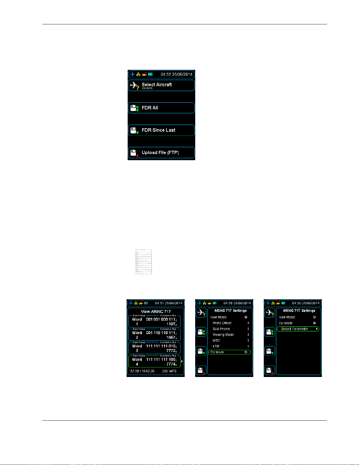
Figure 20.0 Selected tail number on the shortcut screen
2. Follow the procedure in Section 4.4, ”Viewing live flight data” on page 26 and wait
until the HHMPI synchronizes with the FDR, while synchronizing, UNKNOWN is displayed on the screen.
3. Press a shortcut button to select a parameter / word cell.
4. Press right to display the ARINC 717 settings menu.
5. Enable the EU Mode radio button, then press down until you reach the Select
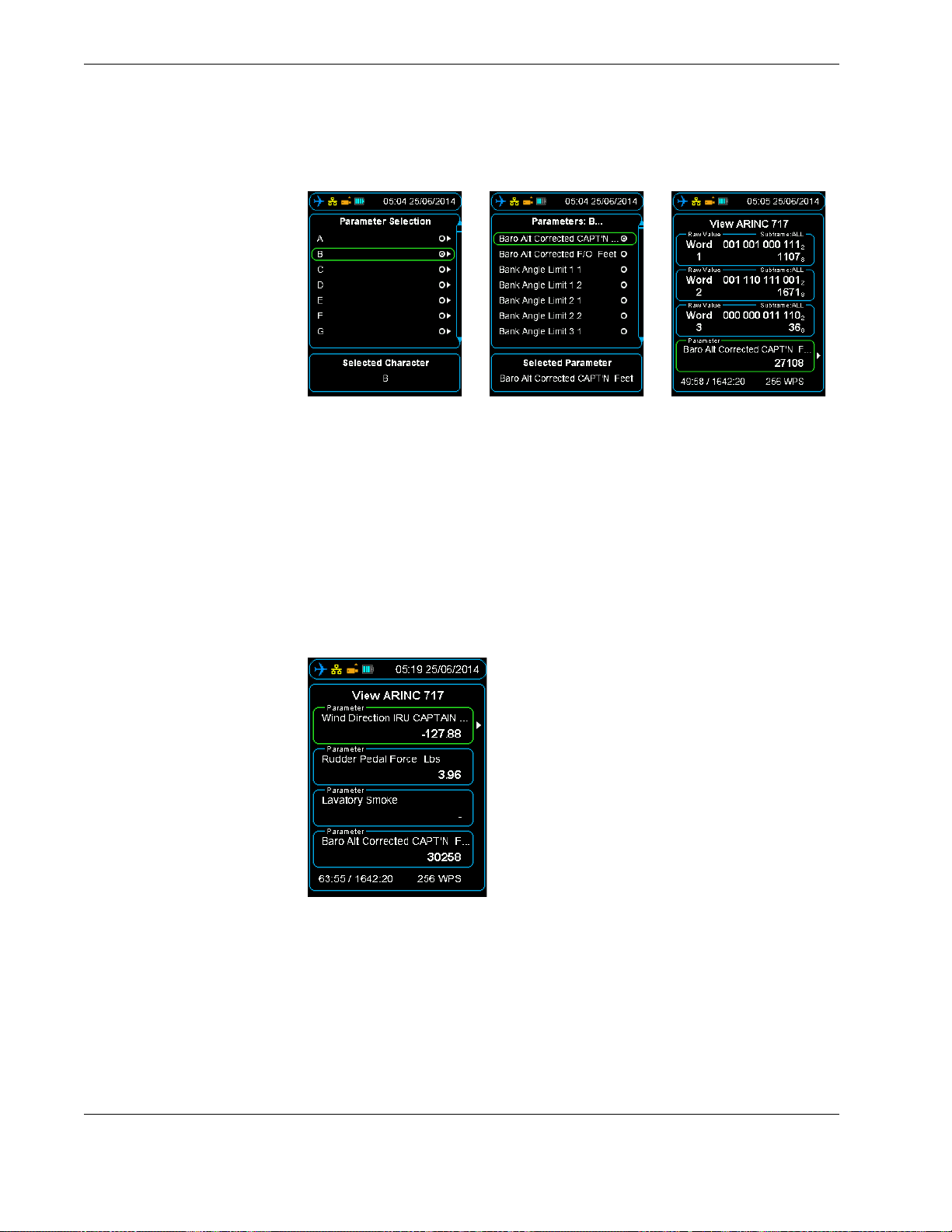
Parameter command, and then press right. An alphabetical list will be displayed, see
Figure 22.0, ”Accessing aircraft parameters alphabetically”, on page 32.
Note The EU Mode radio button will only appear if an aircraft had
been selected that has an Aircraft Definition file (database) assigned
to it.
Figure 21.0 Changing from Raw Mode to EU Mode
Operators manual 31
FDS 400-301
Page 32
Operation
Figure 22.0 Accessing aircraft parameters alphabetically
6. Press right on the first letter of the parameter you want to look at, and then press
right again. This command will display all the parameters starting with the letter you
have selected.
7. Press OK twice to return to the ARINC 717 view. The selected parameter / word cell
will now display live data according to the algorithm in the configured database.
As in the raw data view, up to four parameters / word cells can be displayed and con-
figured independently. Values will update once per sub-frame and SAMPLING will
flash green and white for each update. See Section Figure 23.0, ”Four parameters
populated with Engineering Units” on page 32.
4.6 File transfer operations
Figure 23.0 Four parameters populated with Engineering Units
4.6.1 File transfer between HHMPI storage locations
▼▲
The general method of transferring files between connected memory devices is:
From the Main menu press the down button until you reach the Storage Operations
command, and then press the right button on either the Select Files or Select All
Files command, and then select the preferred memory device.
Main Menu > Storage Operations > Select Files | Select All Files
32 Operators manual
Handheld Multi-Purpose Interface (HHMPI)
Page 33

Operation
Select the file(s) by pressing the right button.
Press the left button to return to the Storage Operations menu.
Select Copy Files then Select Memory Device and press the right button to conf irm.
To delete, select Delete Files.
4.6.2 Other storage operations
To determine the storage used on any memory device, from the Storage Operations
menu, press the right button on the Storage Usage command, and then press the can-
cel button to exit.
4.7 Network operations
▼▲
Main Menu > Storage Operations > Storage Usage
To format a memory device, from the Storage Operations menu, press right on the Format command, and then select the memory device you want to format.
▼▲
Main Menu > Storage Operations > Format > Select Memory Device
4.6.3 File transfer PC to HHMPI
When connected to a PC the internal memory of the HHMPI will appear as a write-protected external hard drive, therefore files may only be copied from the HHMPI to the PC.
To erase files from the HHMPI internal memory, see Section 4.6.1, ”File transfer between
HHMPI storage locations” on page 32.
The HHMPI is capable of transferring files over a network using FTP and also for device
configuration in any web browser.
4.7.1 DHCP network settings
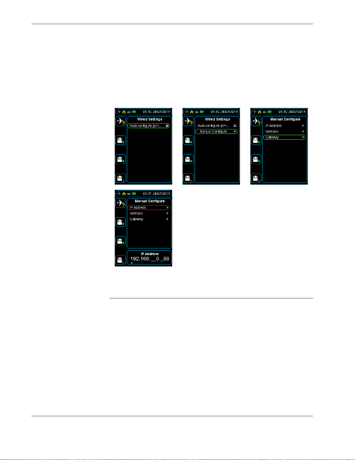
To view DHCP (automatic) network settings:
▼▲
Navigate to Wired Settings as above.
Select Enable Networking, checking or un-checking the check box enables or disa-
bles the Manual Configure IP address option.
Choose between Auto and Manual DHCP.
Auto Configure DHCP by setting the checking the check box.
Main Menu > Device Configuration > Network Settings > Wired Settings
OR
Manually configure the IP address by pressing right on the Manual Configure com-
mand.
Use the up button to set the IP Address, Netmask and Gateway.
Press the OK button.
See Figure 24.0, ”DHCP or manual IP configuration”, on page 34.
Operators manual 33
FDS 400-301
Page 34
Configuring an FTP connection
To view HHMPI IP address:
▼▲
Figure 24.0 DHCP or manual IP configuration
Main Menu > Network Operations > View Wired Address > Adaptor:
eth0
5.0 Configuring an FTP connection
Before you can upload files from the HHMPI to a server, you need to configure the FTP
server settings. You can do this from the HHMPI or through the web interface. Using the
web interface is the easiest way to configure the FTP server settings.
5.1 Adding a new FTP server from the HHMPI
34 Operators manual
To add a new FTP server from the HHMPI, from the Main menu:
▼▲
1. Press down until you reach the Device Configuration command, and then press
right. Then press down until you reach the Network Settings command, and then
press right. Then press down until you reach the FTP Servers command, and then
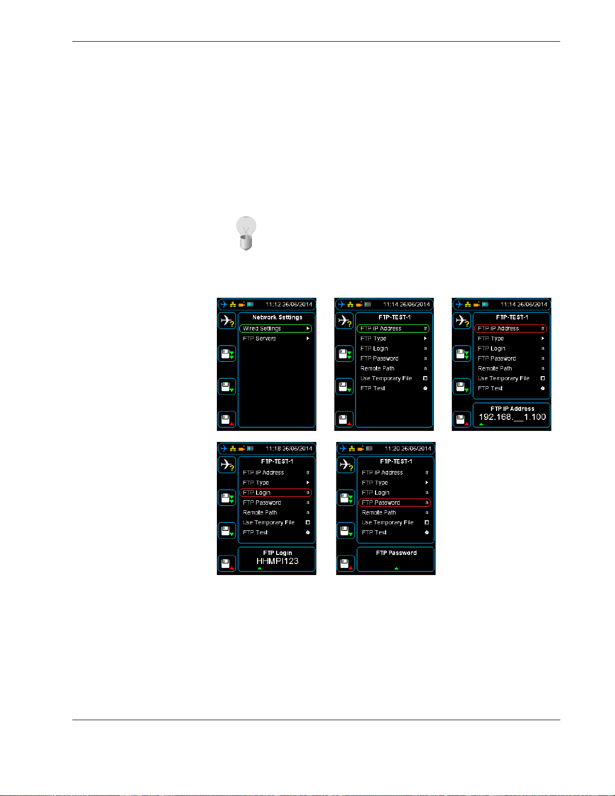
press right. See Figure 25.0, ”Setting up the FTP client”, on page 35.
Main Menu > Device Configuration > Network Settings > FTP Servers >
Add FTP Server
Handheld Multi-Purpose Interface (HHMPI)
Page 35
Configuring an FTP connection
2. Ensure you have access to the FTP server and the FTP server settings, including the IP
address, username, password, and the encryption type. This FTP server information is
usually available from your IT department.
3. From the FTP Servers menu, press down until you reach the Add FTP Server com-
mand, and then press right. To add a FTP server name, press up to enter the name
from the alphabet grid with the arrow buttons, pressing OK between each letter.
When complete, press cancel to exit the alphabet grid, and then press OK to confirm
your selected FTP server name.
Tip The FTP server name is not used in connection to the FTP server,
you can give the FTP server any name.
Figure 25.0 Setting up the FTP client
5.2 Configuring an existing FTP server from the HHMPI
To configure an existing FTP server, from the FTP Servers menu, press down until you
reach the FTP server name you want to configure, and then press right. Then do one of
the following:
1. To save an IP Address, press right on the FTP IP Address command. To enter the IP
Address, press up or down on each number, and then press OK to confirm your
selection.
Operators manual 35
FDS 400-301
Page 36

Configuring an FTP connection
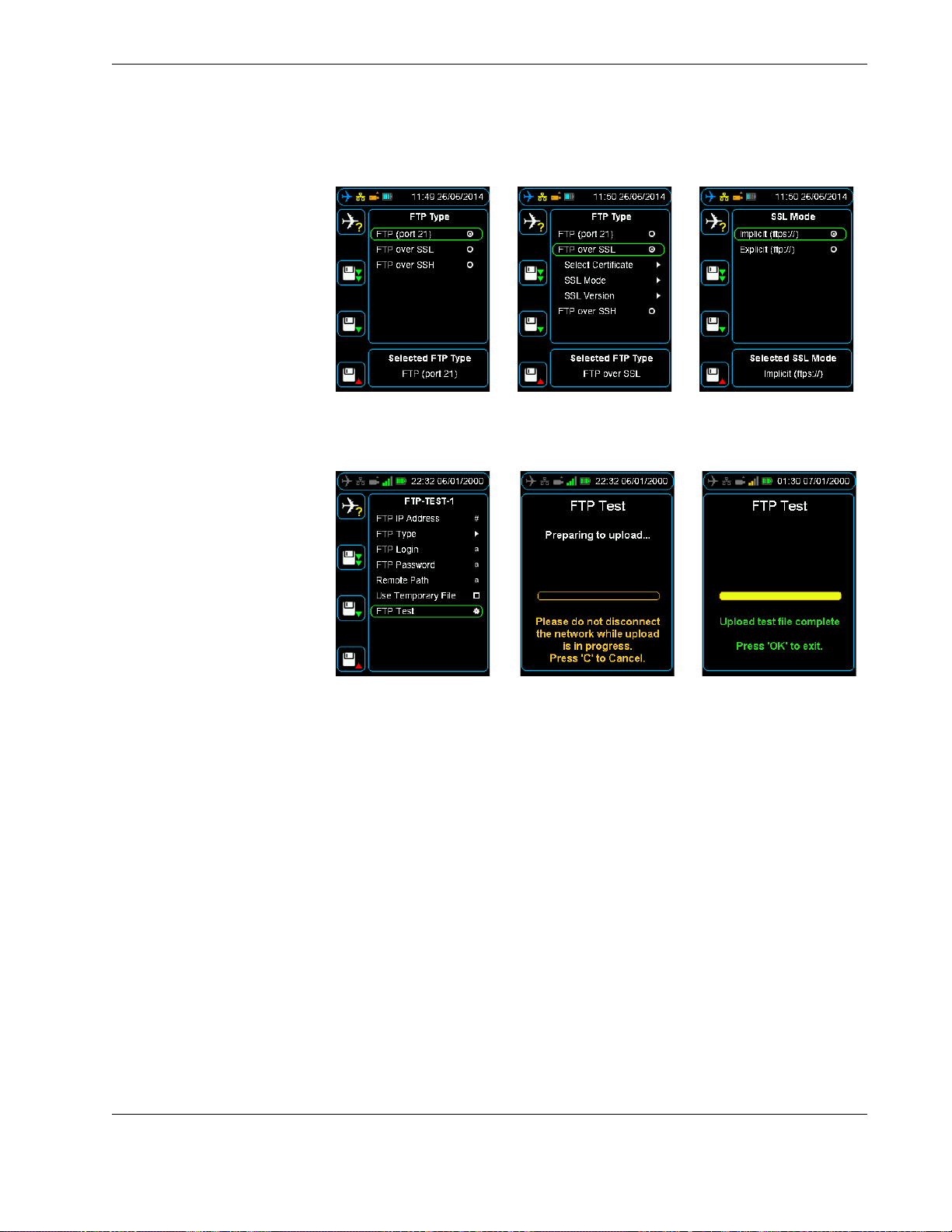
2. To save an FTP Type, press right on the FTP Type command, and then press down
until you reach the FTP type you want, and then press right. The HHMPI supports
three FTP types:
FTP (port 21), unsecured transmission on port 21
FTP over SLL, secured transmission that encrypts the username and pass-
word, and content with SSL
FTP over SSH, secured transmission that encrypts the username and pass-
word, and content with SSH
3. To save an FTP username, press right on the FTP Login command, and then press up
to enter the username from the alphabet grid with the arrow buttons, pressing OK
between each letter. When complete, press cancel to exit the alphabet grid, and then
press OK to confirm the username.
4. To save an FTP password, press right on the FTP Password command, and then press
up to enter the password from the alphabet grid with the arrow buttons, pressing OK
between each letter. When complete, press cancel to exit the alphabet grid, and then
press OK to confirm the password.
5. To s a ve a R e mo t e Pat h , p r es s right on the Remote Path command, and then press up
to enter the remote path from the alphabet grid with the arrow buttons, pressing OK
between each letter. When complete, press cancel to exit the alphabet grid, and then
press OK to confirm the remote path.
The Remote Path field controls which folder the file is uploaded to on the FTP server.
Depending on the FTP server configuration, this may be an optional field. Leaving the
remote path blank means the file will be uploaded to the default folder your FTP
account logs into.
Note Select the Use Temporary File check box if the HHMPI is to
use a temporary file when uploading. When the upload is complete,
this temporary file is renamed to the final f ile name. This is useful for
ensuring that remote systems do not read a partially uploaded file.
Disable this option if the remote server reports a “rename failed”
error and leaves a temporary file with the extension -upload, and the
channel stops. This typically means that the server is employing its
own temporary file mechanism that is incompatible with the HHMPI).
Caution Using an unsecured FTP connection may result in the loss of
sensitive information. See your IT department or contact Flight Data
Systems for more information on encryption.
36 Operators manual
Handheld Multi-Purpose Interface (HHMPI)
Page 37
Configuring an FTP connection
Figure 26.0 FTP type menus
Figure 27.0 Login, password, remote path and FTP test
5.3 Testing an FTP server from the HHMPI
5.4 Setting up an FTP
connection from the
To test an FTP connection, from the FTP Servers menu, press down until you reach the
FTP server name you want to test, and then press right. Then press down until you reach
the FTP Test command, and then press right. See Figure 27.0, ”Login, password, remote
path and FTP test”, on page 37.
You can configure the HHMPI through the web interface in any web-browser. Using the
web interface is the easiest way to configure the HHMPI.
web interface
▼▲
To access the HHMPI web interface:
1. Connect the HHMPI to the local area network (LAN) router or switch which will allo-
cate a unique IP address.
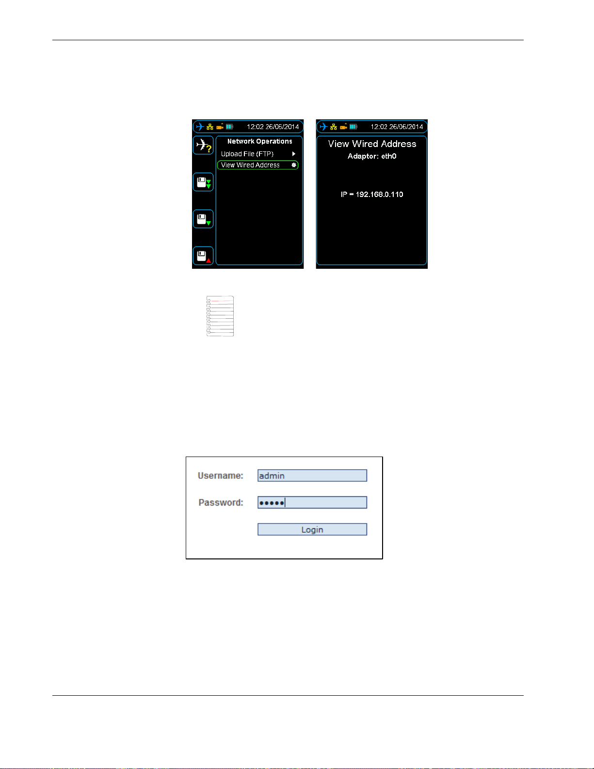
2. From the Main menu, press down until you reach the Network Operations com-
mand, and then press right. Then press down until you reach the View Wired
Address command, and then press right.
If the HHMPI is assigned an IP address it will now be displayed, if no link is detected
No Link Detected will be displayed.
3. Record the IP address. See Figure 28.0, ”Viewing the wired IP address”, on page 38.
Operators manual 37
FDS 400-301
Main Menu > Network Operations > View Wired Address
Page 38
Configuring an FTP connection
Figure 28.0 Viewing the wired IP address
Note If no link is detected an IP address has not been assigned to the
HHMPI, this may be because of you network security settings. See
your IT department or contact Flight Data Systems for more information if this occurs.
1. Open a web-browser such as Mozilla Firefox or Google Chrome and type the wired IP
address into the browser’s address bar.
2. Login to the HHMPI web interface using the default username and password:
Username: admin
Password: admin
See Figure 29.0, ”Web interface login”, on page 38.
Figure 29.0 Web interface login
38 Operators manual
Handheld Multi-Purpose Interface (HHMPI)
Page 39
Configuring an FTP connection
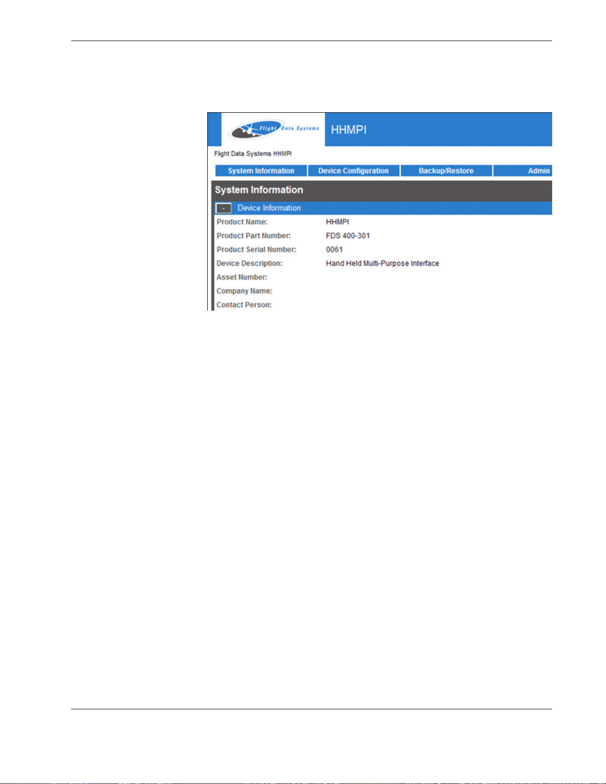
Figure 30.0 Web interface screen
The HHMPI web interface has five tabs:
System Information, displays the device and software version information.
Device Configuration, displays the device configuration, including network settings
and wireless settings.
Backup/Restore, allows you to backup or restore the device configurations.
File Browser, displays a list of the files in the HHMPI internal memory for download.
Admin, displays the administrators configuration, including owner information and
access restrictions.
5.4.1 Changing the HHMPI configuration via the web interface
To configure the HHMPI through the web interface, in any web-browser:
1. Log on to the HHMPI web interface per Section 5.4, ”Setting up an FTP connection
from the web interface” on page 37.
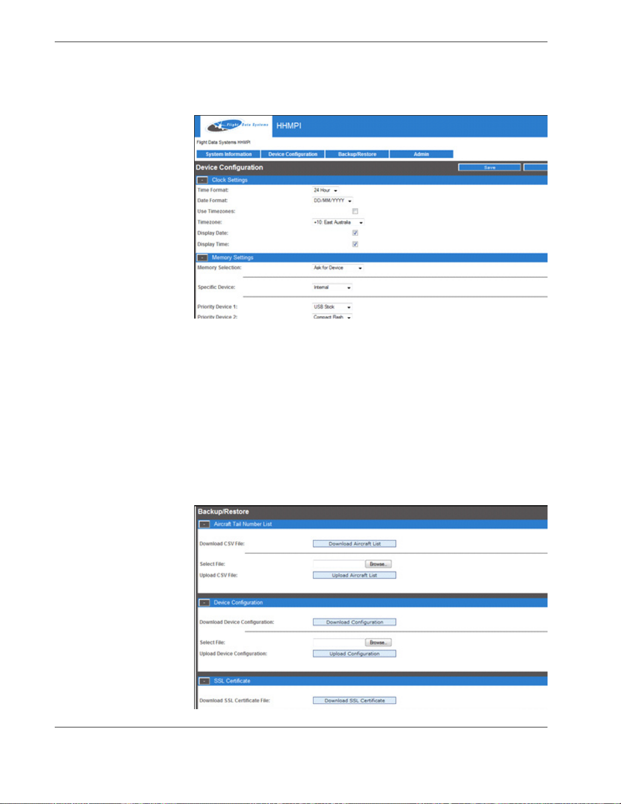
2. Click the Device Configuration tab, see Figure 31.0, ”Device configuration screen”,
on page 40. The Device Configuration screen allows you to configure everything
you can on the HHMPI, including network settings and wireless settings.
3. Save any changes you make, and then click Apply to write the changes to the HHMPI
flash memory.
Operators manual 39
FDS 400-301
Page 40
Configuring an FTP connection
Figure 31.0 Device configuration screen
5.4.2 Backing up the HHMPI configuration
To back up the HHMPI settings, aircraft list and SSL certificate (if installed) through the
web interface, in any web-browser:
1. Log on to the HHMPI web interface per Section 5.4, ”Setting up an FTP connection
from the web interface” on page 37.
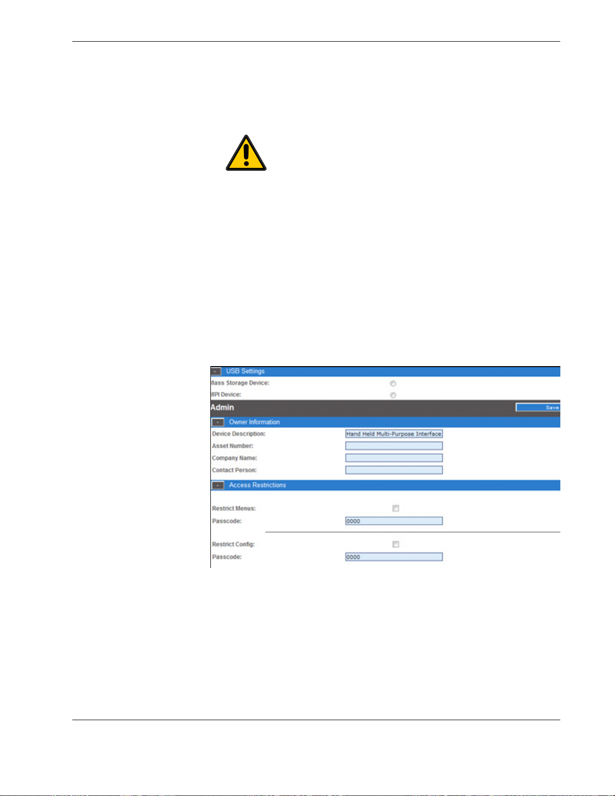
2. Click the Backup/Restore tab, see Figure 31.0, ”Device configuration screen”, on
page 40. The Backup/Restore screen allows you to back up the device configuration,
aircraft list and SSL certificate (if installed) in order to restore it later.
3. Click Aircraft List, and then click Save.
4. Repeat steps 1 to 3 to back up the configuration file and the SSL certificated (if
installed).
Figure 32.0 Device configuration screen
40 Operators manual
Handheld Multi-Purpose Interface (HHMPI)
Page 41
Configuring an FTP connection
5.4.3 Restoring backup files via the web interface
Important The Aircraft List is saved to the USB flash drive as aircraft.csv.bkp. To transfer this file to the HHMPI again, it must be
renamed aircraft.csv.
To reload aircraft.csv or an SSL certificate follow these steps:
1. Select the file to be uploaded, e.g. aircraft.csv or hhmpi.conf.
2. Press the Upload button. Press Apply once the upload has finished, and the changes
will be saved in flash memory in the HHMPI.
5.4.4 Administration settings
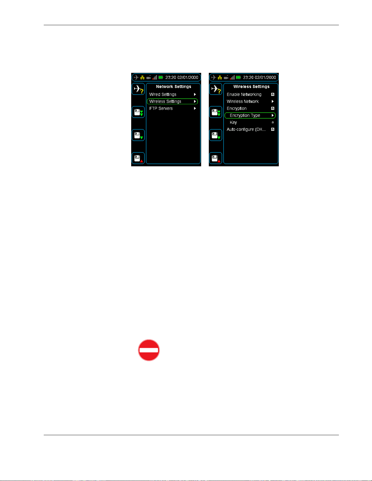
The Admin Screen allows users to:
Add owner information.
Enter pass codes for restricting configuration or restricting main menu access.
Change the administrator login.
Reset the device or restore back to factory settings.
Figure 33.0 Device configuration screen
To change admin settings follow these steps:
1. From the Access Restrictions collapsible menu, set the new passcode and then click
Save.
2. The next time you turn on the HHMPI the new passcode will take effect when
attempting to access the main menu.
5.4.5 Logging out of the web interface
To log out of the web interface press the Logout button below.
Operators manual 41
FDS 400-301
Page 42

Wirelessly uploading files from the HHMPI to a server
Figure 34.0 Logout button
6.0 Wirelessly uploading files from the HHMPI to a server
6.1 Setting up a wireless network connection
Some HHMPI models, when in range of a wireless network, support the wireless upload
of files from the HHMPI to a server. This upload method uses a USB wireless network
adapter plugged into the USB port on top of the HHMPI.
Note The HHMPI must include the wireless option which enables
support for the wireless upload of files from the HHMPI to a server.
USB flash drives cannot be used when connected to a wireless network.
6.1.1 Required equipment and wireless network information
To wirelessly upload files from the HHMPI to a server, you will need:
A HHMPI with the wireless option enabled.
A USB wireless network adaptor.
Access to a wireless network, including the SSID (or the public name of the wireless
network), and the encryption type and key. This wireless network information is usually available from your IT department.
6.1.2 Turning on wireless network support
To wirelessly upload files from the HHMPI to a server, when in range of a wireless network:
▼▲
Main Menu > Device Configuration > Network Settings > Enable Networking > Wireless Network
1. Turn o n t he H H M PI.
2. Plug the USB wireless network adapter into the USB port on the top of the HHMPI. An
alert Configuring Wi-Fi - Please Wait should appear monetarily.
A white antenna icon will also appear in the status bar indicating the HHMPI is ready
to connect to wireless networks in range.
3. From the Main menu, press down until you reach the Device Configuration com-
mand, and then press right. Then press down until you reach the Network Settings
command, and then press right. See Figure 35.0, ”Connecting to a wireless network”,
on page 43.
4. Press right to select the Enable Networking check box.
5. Press down until you reach Wireless Network, and then press right to Scan for wire-
less networks in range, or add a wireless network manually with an ESSID.
42 Operators manual
Handheld Multi-Purpose Interface (HHMPI)
Page 43
Wirelessly uploading files from the HHMPI to a server
Figure 35.0 Connecting to a wireless network
6.1.3 Connecting to a wireless network
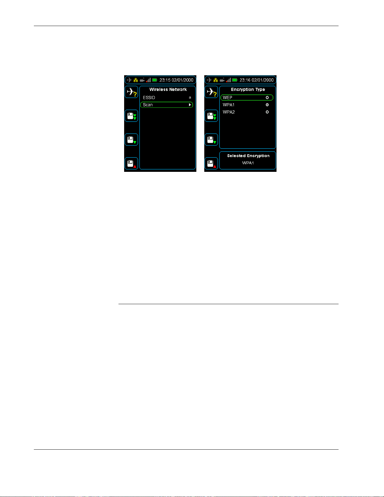
To connect to a wireless network, it is likely that you will need to configure some security
settings like the encryption type and key. To turn on encryption, from the Wireless Set-
tings menu:
Press down until you reach the Encryption command, and then press right to select
the Encryption check box.
To select an encryption type and enter a key, from the Wireless Settings menu:
1. Press down until you reach Encryption Type command, and then press right to
select the encryption type from the following commands: WEP, WPA1, and WPA2.
2. Press left to return to the Wireless Settings menu, then press down to select the
Key command, and then press right to enter the key.
3. Press up to enter the key from the alphabet grid with the arrow buttons, pressing OK
between each letter. When you are finished, press cancel and then OK to return to
the Wireless Settings menu.
If you have successfully connected to a wireless network, the white antenna icon in
the status bar will change to a green four bar signal strength icon. If this signal
strength icon does not appear, you are not connected to a wireless network and may
need to contact your IT department.
Caution Using an unsecured wireless network may result in the loss
of sensitive information. See your IT department or contact Flight
Data Systems for more information on encryption.
To save the encryption type and key, from the Device Configuration menu:
Press down until you reach the Save Settings command, and then press right.
Operators manual 43
FDS 400-301
Page 44
Troubleshooting
Figure 36.0 Configuring security settings like the encryption type and key
6.1.4 Uploading files via FTP with a wireless network connection
When the HHMPI is connected to a wireless network, files saved on the HHMPI, or on
one of its external storage devices, can be uploaded wirelessly to a server via FTP.
To upload files via FTP with a wireless network connection, ensure:
That the HHMPI is connected to a wireless network. From the Main menu, press
down until you reach the Network Operations command, then press down until you
reach the View Wireless Address command, and then press right. If the HHMPI is
connected to a wireless network it will display an IP address assigned by the wireless
router.
That the FTP settings have been configured. See Section 5.0, ”Configuring an FTP
connection” on page 34.
7.0 Troubleshooting
To troubleshoot the HHMP, first try the following steps:
Turn the HHMPI on and off by following the steps in Section 3.2.4, ”Turning on the
HHMPI and self-test” on page 16.
If this did not work, try connecting the HHMPI to a power adapter and plug the
power adapter into an electrical outlet, or connect the HHMPI to your computer.
Make sure the computer is turned on and isn’t set to go to sleep.
If this does not work, try resetting the HHMPI by following the steps in Section 3.2.5,
”Reset operation” on page 16.
Retry the HHMPI with a different recorder if possible.
Restart the recorder if possible and try again.
▼▲
Main Menu > Device Configuration > Report Error
If these steps do not solve your problem, below is a list of potential problems and solutions. If your problem is not listed, use the Report Error menu option (if possible) on the
HHMPI, and send the generated file to [email protected] with a description of
44 Operators manual
Handheld Multi-Purpose Interface (HHMPI)
Page 45

Troubleshooting
the problem, the serial number of the HHMPI, and the part numbers of recorders you are
trying to interface with (if applicable).
If it is not possible to report the error on the HHMPI, send an email to support@flightdata.com.au. In your email, include the following information:
Company name and contact details.
Any relevant part numbers, serial numbers and mod status of the Flight Data Systems
equipment involved in your troubleshooting process. See Section 3.6, ”Information”
on page 19.
Any part numbers and a brief description of any equipment not manufactured by
Flight Data Systems involved in your troubleshooting process.
Reported fault, including as much information about the conditions when the fault
occurs.
Once your email has been received, we will investigate your issue and contact you as
soon as possible.
Table 7.0 Troubleshooting common issues with the HHMPI
Issue Solution
HHMPI does not power up. Battery requires charge, for battery equipped units.
For HHMPIs without an internal battery, ensure that it is connected to a powered recorder.
Screen is not visible Reset the HHMPI by following the steps in Section 3.2.5, ”Reset
No communication between the
HHMPI and the recorder
Unable to download file from
recorder
A message is displaced indicating that the download has
stopped or stalled.
operation” on page 16.
Ensure that the HHMPI is configured for the recorder, see System Information in Section 5.4.1, ”Changing the HHMPI config-
uration via the web interface” on page 39.
Ensure that no external memory device is inserted during startup.
Ensure that the aircraft interface cable is correctly inserted.
Select a memory device, see Section 3.5.3, ”Memory Settings”
on page 17.
Ensure that the aircraft interface cable is correctly inserted.
Ensure that the HHMPI is configured for the recorder, see System Information in Section 5.4.1, ”Changing the HHMPI config-
uration via the web interface” on page 39.
Check the aircraft interface cable for damage.
Check the aircraft interface cable for any debris that could be
causing connection issues.
Cancel and restart the download.
Operators manual 45
FDS 400-301
Page 46

Troubleshooting
Table 7.0 Troubleshooting common issues with the HHMPI
Issue Solution
Cannot see live data in the live
data view, only see unknown values.
Cannot get IP address through
wired network.
Cannot get IP address through
wireless network.
Ensure correct connection to the recorder. Connection is indicated by a blue aircraft icon found in the status bar of the display.
If you want to view the live data in engineering units, ensure
that the aircraft has an aircraft definition (database) associated
with it, see Section 4.5.1, ”Assigning an Aircraft Definition file to
an aircraft” on page 30.
Ensure FDR is in correct mode.
Restart the recorder if possible, and try again.
Ensure that an Ethernet cable is connected, and ensure correct
connection to the recorder. Connection is indicated by a yellow
network connection icon found in the status bar of the display.
See Section 3.5.4, ”Network Settings” on page 18.
If no link is detected an IP address has not been assigned to the
HHMPI, this may be because of you network security settings.
See your IT department or contact Flight Data Systems for more
information if this occurs.
Ensure that the USB wireless network adapter is plugged into
the USB port on the top of the HHMPI, and ensure correct connection to the recorder. Connection is indicated by a white
antennae icon found in the status bar of the display. See
Section 3.5.4, ”Network Settings” on page 18.
Cannot send files from the
HHMPI to an FTP server via a
wired network connection
Ensure wireless networking is enabled.
If no link is detected an IP address has not been assigned to the
HHMPI, this may be because of you network security settings.
See your IT department or contact Flight Data Systems for more
information if this occurs.
Confirm the FTP settings are correct, see Section 5.0, ”Configur-
ing an FTP connection” on page 34.
Ensure that an Ethernet cable is connected, and ensure correct
connection to the recorder. Connection is indicated by a yellow
network connection icon found in the status bar of the display.
See Section 3.5.4, ”Network Settings” on page 18.
If no link is detected an IP address has not been assigned to the
HHMPI, this may be because of you network security settings.
See your IT department or contact Flight Data Systems for more
information if this occurs.
46 Operators manual
Handheld Multi-Purpose Interface (HHMPI)
Page 47

Troubleshooting
Table 7.0 Troubleshooting common issues with the HHMPI
Issue Solution
Cannot send files from the
HHMPI to an FTP server via a
wireless network connection
Cannot copy files from HHMPI to
PC using USB cable.
Cannot load aircraft.csv file. Check the file in Notepad or Excel to see if it meets the format
Confirm the FTP settings are correct, see Section 5.0, ”Configur-
ing an FTP connection” on page 34.
Ensure that the USB wireless network adapter is plugged into
the USB port on the top of the HHMPI, and ensure correct connection to the recorder. Connection is indicated by a white
antennae icon found in the status bar of the display. See
Section 3.5.4, ”Network Settings” on page 18.
Ensure wireless networking is enabled.
If no link is detected an IP address has not been assigned to the
HHMPI, this may be because of you network security settings.
See your IT department or contact Flight Data Systems for more
information if this occurs.
Try another USB port.
Check USB is working and that the PC is displaying the HHMPI
as a mass storage device.
described in Section 4.2.2, ”Creating an Aircraft List on a PC” on
page 20.
Try loading the file through the web interface, see Section 5.4.1,
”Changing the HHMPI configuration via the web interface” on
page 39.
Cannot copy file from external
memory device.
Cannot delete file from media
storage device.
“UV” Displayed on screen. Battery under voltage, charge battery for an extended period
“Detected Battery Fault Condition” error message displayed on
screen.
Ensure that the external memory device is connected. Connection is indicated by an orange USB flash drive icon found in the
status bar of the display.
Check that the file is selected before attempting to copy the f ile.
Check that the external memory device is not full.
Ensure that the external memory device is connected. Connection is indicated by an orange USB flash drive icon found in the
status bar of the display.
Check that the file is selected before attempting to delete the
file.
(12 hours), if the fault message continues to be displayed, return
the unit for repair.
Charge battery for an extended period (12 hours), if the fault
message continues to be displayed, return the unit for repair.
Operators manual 47
FDS 400-301
Page 48

FA2100, FA2200 and FA2300 Interface Supplement
Table 7.0 Troubleshooting common issues with the HHMPI
Issue Solution
“Unsupported Cable Detected” Ensure that the aircraft interface cable is correctly inserted.
“Mount Error” Ensure that the external memory device is not corrupt or dam-
8.0 FA2100, FA2200 and FA2300 Interface Supplement
This supplement details the additional functions supported by the L-3 Aviation Recorders
FA2100 CVFDR. For specific details on these recorders, refer to the appropriate L-3
FA2100 CVFDR OEM documentation.
Ensure that the HHMPI is configured for the recorder, see System Information in Section 5.4.1, ”Changing the HHMPI config-
uration via the web interface” on page 39.
Check the aircraft interface cable for damage.
Check the aircraft interface cable for any debris that could be
causing connection issues.
aged in anyway.
Ensure that the external memory device is correctly inserted in
the HHMPI.
8.1 Download Operations
8.2 Recorder Operations
The FA2100 supports the following download options:
FDR All - Retrieves all flight data from the recorder.
FDR Since Last - Retrieves only new flight data recorded since the last download oper-
ation was performed.
FDR Time - Retrieves the last specified duration of flight data.
FDR Mark - Retrieves all flight data newer than a specified memory mark.
CVR All - Retrieves all cockpit voice recordings from the recorder. If CVR de-multiplex-
ing is enabled on the HHMPI, recordings can also be decompressed so they can be
played on a PC or other device.
CVR Time - Retrieves the last specified duration of cockpit voice recordings.
See Section 4.3, ”Downloading flight data” on page 23.
Table 8.0 File extensions of files downloaded from the FA2100
Data Type Extension
FDR fdr
CVR cvr
Faul t Log log
Debug Trace log
The FA2100 supports the following recorder operations:
Monitoring of FDR Status.
Monitoring of CVR Status.
Setting of FDR and CVR memory markers.
48 Operators manual
Handheld Multi-Purpose Interface (HHMPI)
Page 49
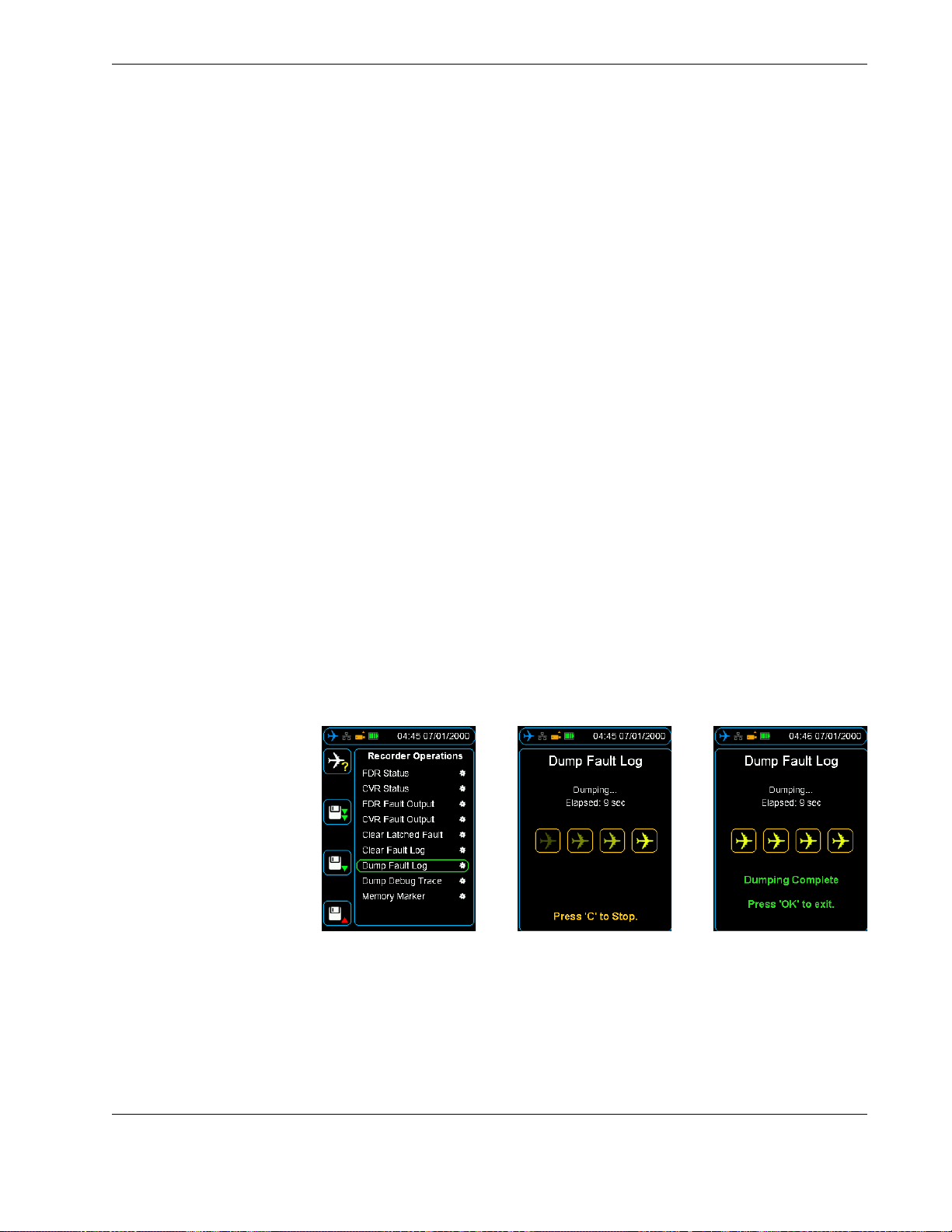
FA2100, FA2200 and FA2300 Interface Supplement
Clearing of latched faults and fault log.
Download of CVFDR fault logs. See Figure 37.0, ”FA2100 Recorder Operations - Dump
Debug Trace”, on page 49.
8.3 FDR Status Indicates the status of the following:
FDR Stream Detected
Frame Lock
Recorded Minutes
Latched
Fault
8.4 CVR Status Indicates the status of the following:
Latched
Fault
Recording
8.5 FDR or CVR Fault
The cockpit fault light can be forced on or off using the left and right buttons.
Output
8.6 Clear Latched Fault Sets or reset the fault log.
8.7 Clear Fault Log Erases the fault log.
8.8 Dump Fault Log Saves the fault log to selected memory. See Figure 37.0, ”FA2100 Recorder Operations -
Dump Debug Trace”, on page 49.
Figure 37.0 FA2100 Recorder Operations - Dump Debug Trace
8.9 Dump Debug Trace This function dumps the running debug stream from an L3 FA2100 recorder to a file on
the HHMPI. This file is a text file readable in any text editor.
8.10 Memory Marker Set a new FDR memory marker. The next marker will be chosen in the range 1-15, when
all the markers are set, the marker count returns to 1.
Operators manual 49
FDS 400-301
Page 50
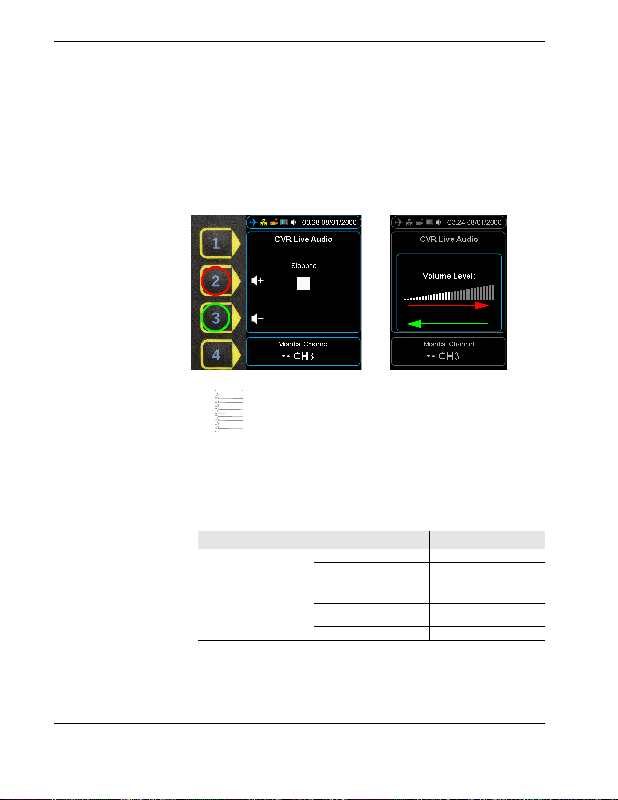
FA2100, FA2200 and FA2300 Interface Supplement
8.11 Audio Operations The FA5000/FA5001 audio can be both monitored in real time, and also play back previ-
ously recorded data. To listen to audio, plug headphones into the audio jack on the bottom of the HHMPI, see Figure 3.0, ”HHMPI bottom view”, on page 7.
Press the up and down buttons to select which channel you want to listen to. Shortcut
button 2 increases the volume and shortcut button 3 decreases the volume. In playback
mode, the left and right buttons rewind or fast forward the current playback position.
See Figure 38.0, ”CVR Live Audio volume control”, on page 50.
Figure 38.0 CVR Live Audio volume control
Note The CVFDR must be configured appropriately for playback,
that is, not currently recording. Refer to the component maintenance
manual for instructions.
8.12 Live Data View Real time ARINC-717 data can be monitored from the FA2100. See Section 4.4, ”Viewing
live flight data” on page 26.
8.13 Menu Tree The following menu items are enabled on connection to a FA5000/FA5001 recorder.
Table 9.0 Additional menu items for FA2100 CVFDR
Main Menu Menu Level 1 Menu Level 2
Download Operations
(Section 4.3, ”Downloading
flight data” on page 23)
FDR All
FDR Since Last
FDR Mark
FDR Time
CVR All CVR Decompression (OK/Can-
cel)
CVR Time
50 Operators manual
Handheld Multi-Purpose Interface (HHMPI)
Page 51

SRVIVR™ Interface Supplement
Table 9.0 Additional menu items for FA2100 CVFDR
Main Menu Menu Level 1 Menu Level 2
Recorder Operations FDR Status FDR Stream Detected
CVR Status Latched
FDR Fault Output Forced On/Off
CVR Fault Output
Clear Latched Fault Set/Reset
Clear Fault Log
Dump Fault Log Select memory
Dump Debug Trace
Memory Marker Set a memory marker (1-15)
Audio Operations CVR Live Audio Select Monitor Channel: HQV1,
CVR Playback Select Playback Channel:
Live Data View (Section 4.4,
”Viewing live flight data” on
page 26)
View Live Data
Frame Lock
Recorded Minutes
Latched
Fault
Fault
Recording
HQV2, HQV3, SQN, SQC, HQC.
Audio volume
Data Rate
HQV1, HQV2, HQV3, SQN,
SQC, HQC.
Playback status
Playback audio volume
Playback data Rate
9.0 SRVIVR™ Interface Supplement
This supplement details the additional functions supported by the L-3 Aviation Recorders
SRVIVR™ CVFDR. For specific details on these recorders, refer to the appropriate L-3
SRVIVR™ OEM documentation.
9.1 Download Operations
Operators manual 51
FDS 400-301
The SRVIVR™ supports the following download options:
CVR All - Retrieves all cockpit voice recordings from the recorder.
CVR Since Last - Retrieves only new cockpit voice recordings recorded since the last
download operation was performed.
CVR Last Flight - Retrieves only new cockpit voice recordings recorded since the last
flight.
CVR Time - Retrieves the last specified duration of flight data.
DLR All - Retrieves all Datalink recordings from the recorder.
DLR Since Last - Retrieves only new Datalink recordings recorded since the last down-
load operation was performed.
DLR Last Flight - Retrieves only new Datalink recordings recorded since the last flight.
DLR Time - Retrieves the last specified duration of Datalink recordings.
Page 52
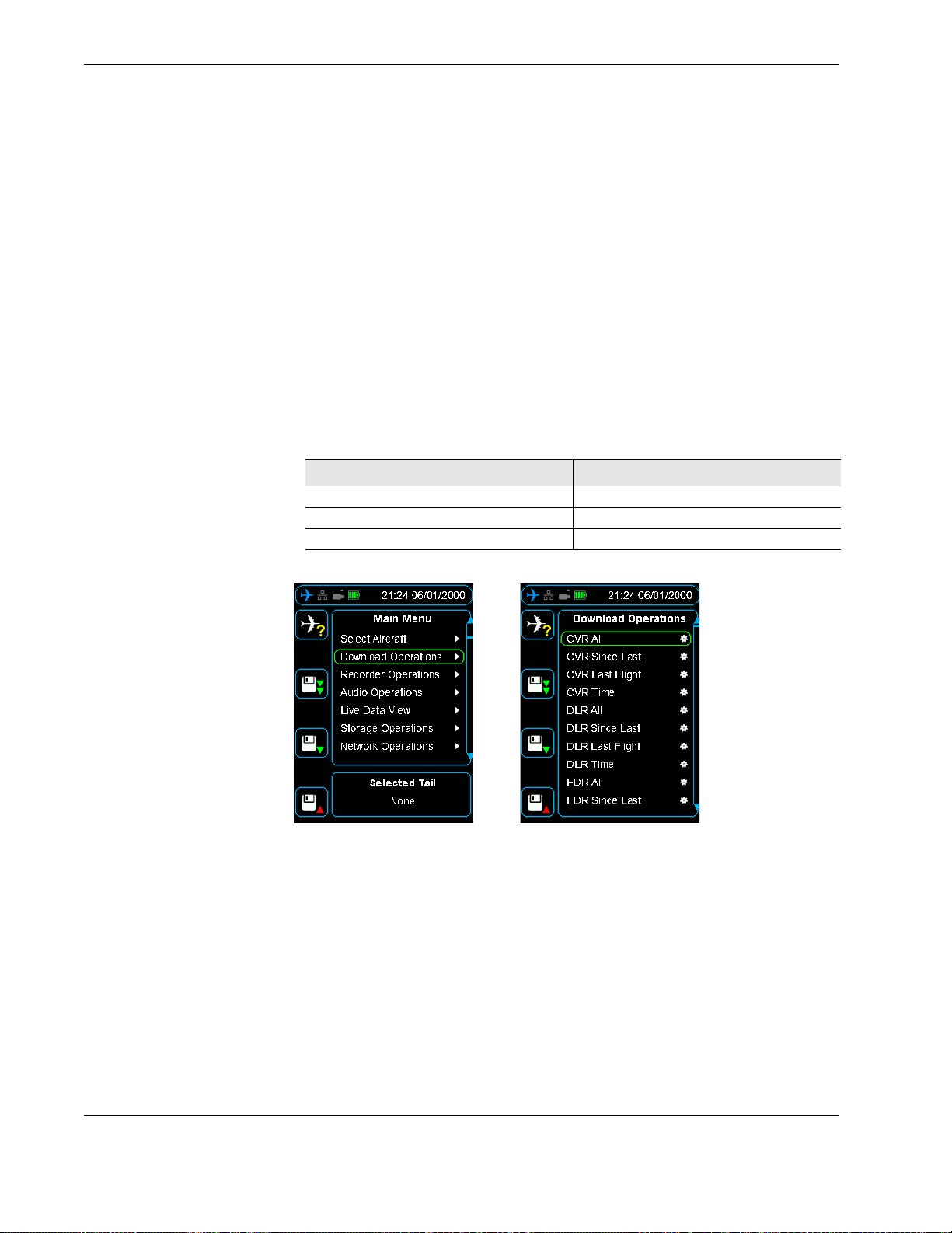
SRVIVR™ Interface Supplement
FDR All - Retrieves all flight data from the recorder.
FDR Since Last - Retrieves only new flight data recorded since the last download oper-
ation was performed.
FDR Last Flight - Retrieves only new flight data recorded since the last flight.
FDR Time - Retrieves the last specified duration of flight data.
BIT All - Retrieves all BIT data from the recorder for SRU fault isolation.
BIT Since Last - Retrieves only new BIT data recorded since the last download opera-
tion was performed.
BIT Last Flight - Retrieves only new BIT data recorded since the last flight.
BIT Time - Retrieves the last specified duration of BIT data.
See Figure 39.0, ”SRVIVR™ Download Operations”, on page 52 and Section 4.3, ”Down-
loading flight data” on page 23.
Table 10.0 File extensions of files downloaded from the SRVIVR™
Data Type Extension
FDR dfd
CVR mic1, mic2, mic3, cam
DLR dlk
9.2 Recorder Operations
Figure 39.0 SRVIVR™ Download Operations
The SRVIVR™ supports the following recorder operations:
Monitoring of CVFDR information, including system version, serial number etc. For full
list of information, see Table 11.0, “Additional menu items for SRVIVR™ CVFDR,” on
page 54 and Figure 40.0, ”SRVIVR™ Recorder Operations - Information”, on page 53.
Initiating system self test, see Figure 41.0, ”SRVIVR™ Recorder Operations - Self Test”,
on page 53.
52 Operators manual
Handheld Multi-Purpose Interface (HHMPI)
Page 53
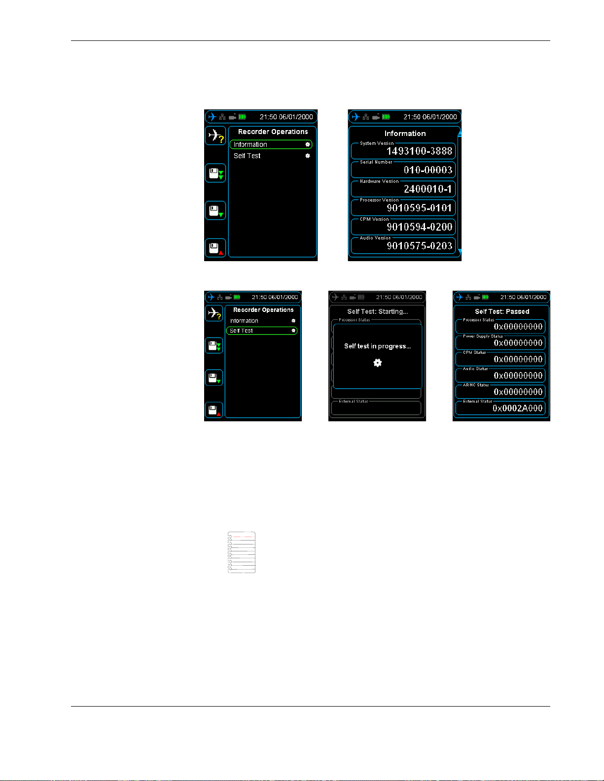
SRVIVR™ Interface Supplement
Figure 40.0 SRVIVR™ Recorder Operations - Information
Figure 41.0 SRVIVR™ Recorder Operations - Self Test
9.3 Audio Operations The SRVIVR™™ audio can be monitored in real time. To listen to audio, plug headphones
into the audio jack on the bottom of the HHMPI, see Figure 3.0, ”HHMPI bottom view”,
on page 7.
Press the up and down buttons to select which channel you want to listen to. Shortcut
button 2 increases the volume and shortcut button 3 decreases the volume. See
Figure 45.0, ”CVR Live Audio volume control”, on page 58.
Note The CVFDR must be configured appropriately for playback,
that is, not currently recording. Refer to the component maintenance
manual for instructions.
9.4 Live Data View Three streams of real time data can be monitored from the SRVIVR™:
Live ARINC-717, see Section 4.4, ”Viewing live flight data” on page 26.
Monitoring of Captain’s Clock on the ARINC-429 GMT BUS, both labels 125 and 150.
Monitoring of Rotor Frequency in Hz.
Operators manual 53
FDS 400-301
Page 54

SRVIVR™ Interface Supplement
9.5 Menu Tree The following menu items are enabled on connection to a SRVIVR™ recorder.
Table 11.0 Additional menu items for SRVIVR™ CVFDR
Main Menu Menu Level 1 Menu Level 2
Download Operations
(Section 4.3, ”Downloading
flight data” on page 23)
Recorder Operations Information System Version
CVR All
CVR Since Last
CVR Last Flight
CVR Time
DLR All
DLR Since Last
DLR Last Flight
DLR Time
FDR All
FDR Since Last
FDR Last Flight
FDR Time
BIT All
BIT Since Last
BIT Last Flight
BIT Time
Serial Number
Hardware Version
Processor Ver sion
CPM Version
Audio Version
ARINC Version
Boot Version
OFP Version
OFP CRC
Config Data Version
Config Data CRC
Operating Hours
Last Time Stamp
CVFDR Mode
Discrete Inputs
Discrete Outputs
CVR Status Word
Processor Status
Power Supply Status
CPM Status
Audio Status
ARINC Status
External Status
Self Test Processor Status
Power Supply Status
CPM Status
Audio Status
ARINC Status
External Status
54 Operators manual
Handheld Multi-Purpose Interface (HHMPI)
Page 55

FA5000/FA5001 Interface Supplement
Table 11.0 Additional menu items for SRVIVR™ CVFDR
Main Menu Menu Level 1 Menu Level 2
Audio Operations CVR Live Audio Select Monitor Channel: HQV1,
Live Data View (Section 4.4,
”Viewing live flight data” on
page 26).
View Live FDR Data
View DLR DLR Heartbeat
View Captains Clock Label 150 Clock (HH:MM:SS)
View Rotor Raw Rotor Frequency
HQV2, HQV3, SQN, SQC, HQC.
Audio volume
Data Rate
DLR Data
Label 125 Clock (HH:MM:SS)
10.0 FA5000/FA5001 Interface Supplement
This supplement details the additional functions supported by the L-3 Aviation Recorders
FA5000/FA5001 CVFDR. For specific details on these recorders, refer to the appropriate L3 FA5000/FA5001 OEM documentation.
10.1 Download Operations
The FA5000/FA5001 supports the following download options:
FDR All - Retrieves all flight data from the recorder.
FDR Since Last - Retrieves only new flight data recorded since the last download oper-
ation was performed.
FDR Time - Retrieves the last specified duration of flight data.
FDR Mark - Retrieves all flight data newer than a specified memory mark.
CVR All - Retrieves all cockpit voice recordings from the recorder.
CVR Since Last - Retrieves only new cockpit voice recordings recorded since the last
download operation was performed.
CVR Time - Retrieves the last specified duration of cockpit voice recordings.
CVR Mark - Retrieves all cockpit voice recordings newer than a specified memory
mark.
DLR All - Retrieves all Datalink recordings from the recorder.
DLR Since Last - Retrieves only new Datalink recordings recorded since the last down-
load operation was performed.
DLR Mark - Retrieves all Datalink recordings newer than a specified memory mark.
See Figure 42.0, ”FA5000/FA5001 Download Operations”, on page 56 and Section 4.3,
”Downloading flight data” on page 23.
FDR All - Retrieves all flight data from the recorder.
FDR Since Last - Retrieves only new flight data recorded since the last download oper-
ation was performed.
FDR Time - Retrieves the last specified duration of flight data.
FDR Mark - Retrieves all flight data newer than a specified memory mark.
CVR All - Retrieves all cockpit voice recordings from the recorder.
Operators manual 55
FDS 400-301
Page 56
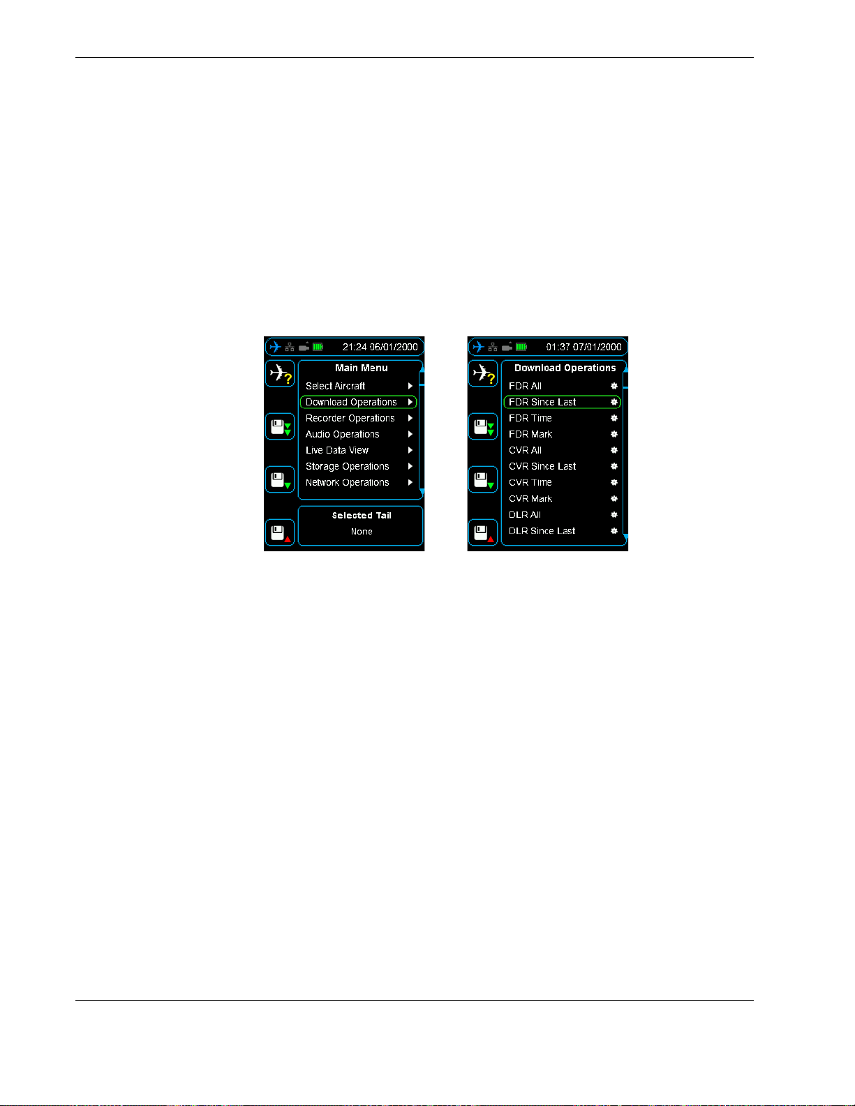
FA5000/FA5001 Interface Supplement
CVR Since Last - Retrieves only new cockpit voice recordings recorded since the last
download operation was performed.
CVR Time - Retrieves the last specified duration of cockpit voice recordings.
CVR Mark - Retrieves all cockpit voice recordings newer than a specified memory
mark.
DLR All - Retrieves all Datalink recordings from the recorder.
DLR Since Last - Retrieves only new Datalink recordings recorded since the last down-
load operation was performed.
DLR Mark - Retrieves all Datalink recordings newer than a specified memory mark.
Figure 42.0 FA5000/FA5001 Download Operations
10.2 Recorder Operations
The FA5000/FA5001 supports the following recorder operations:
Monitoring of FDR Status. See Figure 43.0, ”FA5000/FA5001 Recorder Operations -
FDR Status”, on page 57.
Monitoring of CVR Status.
Setting of FDR, CVR and DLR memory markers.
Download of CVFDR fault logs. See Figure 44.0, ”FA5000/FA5001 Recorder Operations
- Dump Log”, on page 57.
Download EDS file. Get the ARINC 717 Engineering Documentation Standard (EDS)
conversion file (FRCS, FRED, etc.) from the recorder.
56 Operators manual
Handheld Multi-Purpose Interface (HHMPI)
Page 57
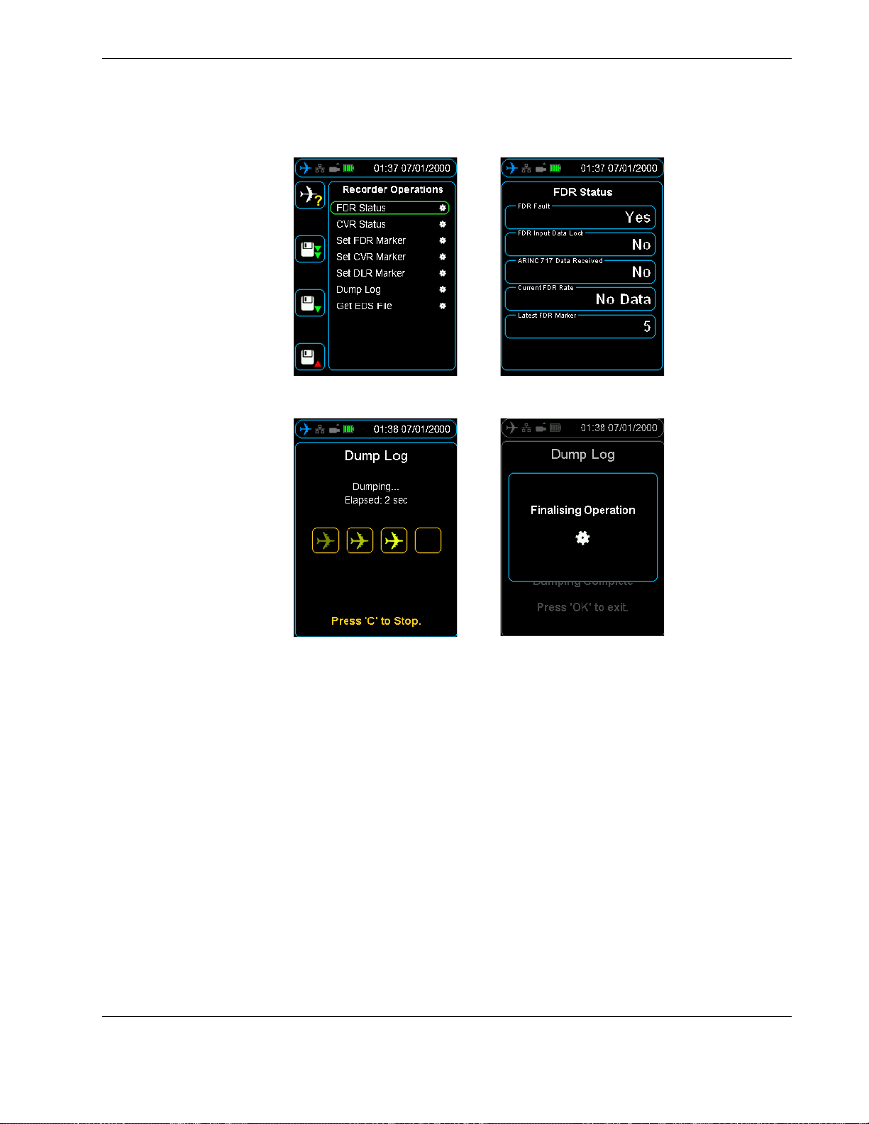
FA5000/FA5001 Interface Supplement
Figure 43.0 FA5000/FA5001 Recorder Operations - FDR Status
Figure 44.0 FA5000/FA5001 Recorder Operations - Dump Log
10.3 FDR Configuration
The FDR configuration menu details information about the recorder such as part numbers and version numbers.
10.4 Audio Operations The FA5000/FA5001 audio can be both monitored in real time, and also play back previ-
ously recorded data. To listen to audio, plug headphones into the audio jack on the bottom of the HHMPI, see Figure 3.0, ”HHMPI bottom view”, on page 7.
Press the up and down buttons to select which channel you want to listen to. Shortcut
button 2 increases the volume and shortcut button 3 decreases the volume. In playback
mode, the left and right buttons rewind or fast forward the current playback position.
See Figure 45.0, ”CVR Live Audio volume control”, on page 58.
Operators manual 57
FDS 400-301
Page 58
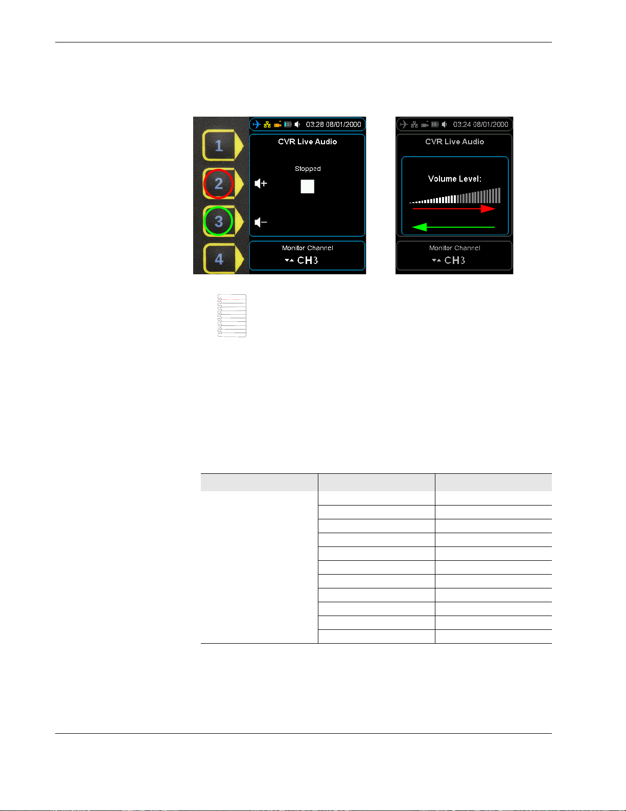
FA5000/FA5001 Interface Supplement
Figure 45.0 CVR Live Audio volume control
Note The CVFDR must be configured appropriately for playback,
that is, not currently recording. Refer to the component maintenance
manual for instructions.
10.5 Live Data View Three streams of real time data can be monitored from the FA5000/FA5001:
Live ARINC-717, see Section 4.4, ”Viewing live flight data” on page 26.
Monitoring of Captain’s Clock on the ARINC-429 GMT BUS, both labels 125 and 150.
Monitoring of Rotor Frequency in Hz.
10.6 Menu Tree The following menu items are enabled on connection to a FA5000/FA5001 recorder.
Table 12.0 Additional menu items for FA5000/FA5001 CVFDR
Main Menu Menu Level 1 Menu Level 2
Download Operations
(Section 4.3, ”Downloading
flight data” on page 23)
FDR All
FDR Since Last
FDR Time
FDR Mark
CVR All
CVR Since Last
CVR Time
CVR Mark
DLR All
DLR Since Last
DLR Mark
58 Operators manual
Handheld Multi-Purpose Interface (HHMPI)
Page 59

FA5000/FA5001 Interface Supplement
Table 12.0 Additional menu items for FA5000/FA5001 CVFDR
Main Menu Menu Level 1 Menu Level 2
Recorder Operations FDR Status FDR Fault
CVR Status CVR Fault
Set FDR Marker Memory Marker - in progress or
Set CVR Marker Memory Marker - in progress or
Dump Log List of storage devices
Get EDS File List of storage devices
FDR Configuration Information Recorder Part Number
Audio Operations CVR Live Audio Select Monitor Channel: HQV1,
CVR Playback Select Playback Channel:
Live Data View (Section 4.4,
”Viewing live flight data” on
page 26)
View Live Data
View Captains Clock Label 150 Clock (HH:MM:SS)
View Rotor Raw Rotor Frequency
FDR Input Data Lock
ARINC 717 Data Received
Current FDR Rate
Latest FDR Marker
Datalink Data Received
GMT Data Received
OMS Data Received
Rotor Data Received
CAM Audio Present and Sending Data
MIC1 Audio Present and Sending Data
MIC1 Audio Present and Sending Data
MIC1 Audio Present and Sending Data
Latest CVR Marker
marker number
marker number
Aircraft ID
Recorder Serial Number
Date(YYYY/MM/DD)
Time(HH:MM:SS:MS)
FW Version
L3 HW FPGA Part Number
L3 HW FPGA Part Number
Revision
L3 FW FPGA Part Number
L3 FW FPGA Part Number Revision
L3 FPGA FW Date (DD/MM/
YYYY)
PN Unknown1
PN Unknown2
HQV2, HQV3, SQN, SQC, HQC.
Audio volume
Data Rate
HQV1, HQV2, HQV3, SQN,
SQC, HQC.
Playback status
Playback audio volume
Playback data Rate
Label 125 Clock (HH:MM:SS)
Operators manual 59
FDS 400-301
Page 60
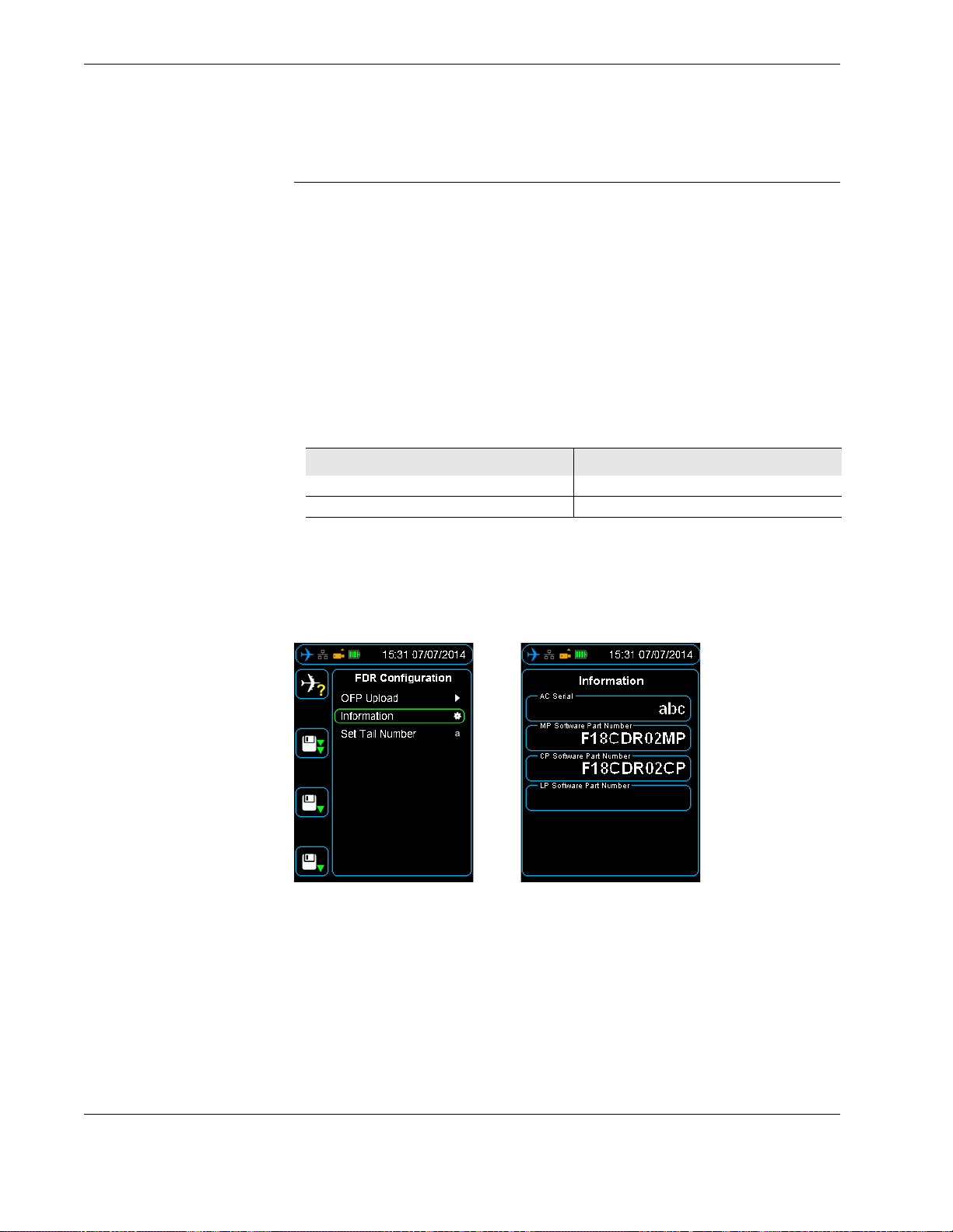
SMITHS VADR Interface Supplement
11.0 SMITHS VADR Interface Supplement
This supplement details the additional functions supported by the Smiths VADR. For specific details on these recorders, refer to the appropriate Smiths VADR OEM documentation.
11.1 Select Aircraft The Smiths VADR Select Aircraft menu is pre-installed with ARMY and RAAF models and
registration information. See Figure 4.2.5, ”Adding Entries to the HHMPI Aircraft File”, on
page 21 to add additional aircraft.
11.2 Download Operations
11.3 FDR Configuration
The Smiths VADR supports the following download options:
FDR All - Retrieves all flight data from the recorder.
CVR All - Retrieves all cockpit voice recordings from the recorder.
Table 13.0 File extensions of files downloaded from the Smiths VADR
Data Type Extension
FDR .rdf
CVR .rdf
The FDR configuration menu details information such as aircraft serial number, version
numbers (MP Software P/N and CP Software P/N), upload of Operational Flight Program
(OFP) and settings for the aircraft tail number. See Figure 46.0, ”VADR information”, on
page 60.
Figure 46.0 VADR information
11.4 Upload OFP to the HHMPI
To upload OFP to the HHMPI:
1. Power up the HHMPI and connect to the VADR using a VADR aircraft interface cable.
2. Insert a USB flash drive into the USB port on top of the HHMPI containing the OFP
files.
3. From the Main menu, press down until you reach the FDR Conf iguration command,
and then press right.
4. Select OFT upload, and then select the .cpi file from the USB flash drive and confirm
the selection by pressing the OK button.
5. Repeat step 4 for the .mpi file.
60 Operators manual
Handheld Multi-Purpose Interface (HHMPI)
Page 61
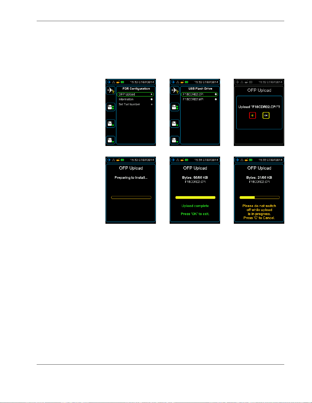
SMITHS VADR Interface Supplement
Once complete return to the FDR Configuration and confirm the files are loaded in the
information section. See Figure 47.0, ”Uploading OFP to the VADR from the HHMPI”, on
page 61.
Figure 47.0 Uploading OFP to the VADR from the HHMPI
Operators manual 61
FDS 400-301
 Loading...