

FLI Audio LOADED 900s Instruction Manual

loaded
amplifier
www.fliaudio.co.uk
Model: FLI LOADED 900s

Limited Warranty
All FLI goods are covered by a full twelve months warranty. Valid from
the date of the original receipt and proof of purchase. In order to
validate this warranty, the warranty card should be returned to FLI
within seven days of the original purchase date. The original receipt
and packaging should also be kept for this twelve month period.
If at any stage during the warranty period you have a problem with the
product then it should be returned to the point of purchase in its
original packaging, complete and with no items missing.
If the store is unable to fix the product it may have to be returned to
FLI this process takes around 7 working days.
A full description of FLI's warranty information can be found on our
website:
www.fliaudio.co.uk/warranty
A written version can also be obtained from
FLI warranty department
PO Box 11000
B75 7WG
Copyright
All content included in this manual such as text, graphics, logos, icons, images data, the selection and arrangement
thereof, are the property of FLI Audio (herein referred to as "FLI", "us" or "we") and its affiliate or their content and
technology providers, and are protected by United Kingdom and International copyright laws. All rights reserved.
Trademarks
FLI FrequencyTM, FLI IntegratorTM , FLI LoadedTM , FLI Trap PassiveTM, FLI Trap ActiveTM , and FLI Trap TwinTM
and all stylised representations of product names, or the abbreviations of product names, as logos are all trademarks of
FLI's trademarks and trade dress may not be used in connection with any product or service that is not FLI's, in any
manner that is likely to cause confusion among customers or in any manner that disparages or discredits FLI. All other
trademarks not owned by FLI or its subsidiaries that appear in this manual are the property of their respective owners,
FLI. Graphics and logos are trademarks or trade dress of FLI Audio or its subsidiaries.
who may or may not be affiliated with, connected to, or sponsored by FLI or its subsidiaries.
We reserve the right to make needed changes or improvements to the product ,
without informing the customer about this in advance.
2
Thank you for purchasing this FLI amplifier. It will provide you with a lifetime of trouble free use
Mounting Guidelines
Your FLI amplifier is designed with a swift installation routine in mind. Please mount the amplifier in a dry location on a solid
surface. NEVER mount the amplifier upside down, this will cause the amplifier to over heat and will eventually damage the
amplifier. Before fixing the amplifier in place
least two inches will be sufficient.
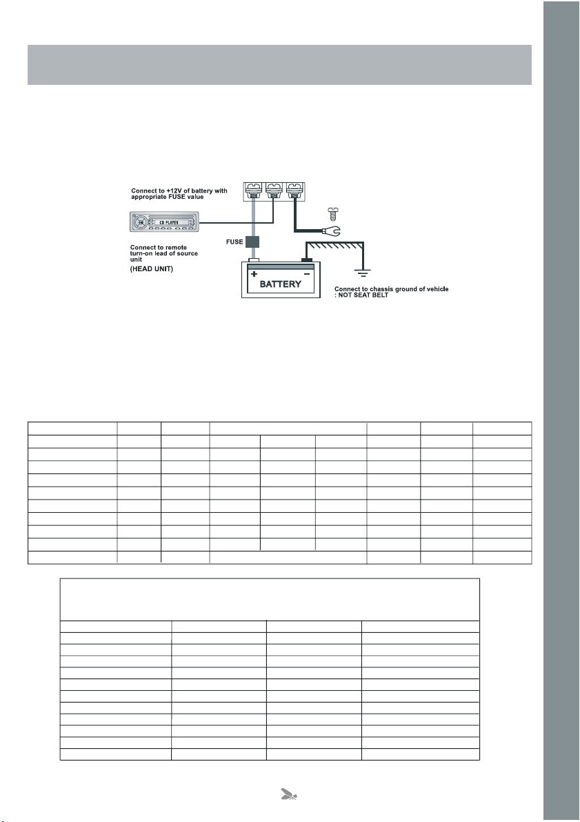
Connections
Power Cable
● At least an 8 gauge cable should be used for both the power and the ground connections to the amplifier.
● The power cable should be taken directly from the battery. Rubber grommets should be used when passing through any
bulkheads to prevent the cable from becoming chaffed or cut.
● It is vital that a fuse / circuit breaker (of at least equal value to the one fitted on the amplifier) is placed in line with the
power cable and is no further than eighteen inches away from the battery.
● Please ensure that the fuse is not fitted until the entire installation procedure is complete.
● The two tables below are to help you decide on what cable is correct for you. The first enables you to select the size of
cable depending on the length required. The second will help you convert the cable size from American Wire Gauge to
Metric if you need to.
providing you follow a few simple guidelines.
please ensure that there is sufficient air flow around the exterior of the casing, at
Current demand 0 – 4 Ft 4 – 7 Ft 7 – 10 Ft 10 – 13 Ft 13 – 16 Ft 16 – 19 Ft 19 – 22 Ft 22 – 28 Ft
0–20 amps 14 12 12 10 10 8 8 8
20–35 amps 12 10 8 8 6 6 6 4
35–50 amps 10 8 8 6 4 4 4 4
50–65 amps 8 8 6 4 4 4 4 2
65–85 amps 6 6 4 4 2 2 2 0
85–105 amps 6 6 4 2 2 2 2 0
105–125 amps 4 4 4 2 0 0 0 0
125–150 amps 2 2 2 0 0 0 0 0
AWG to Metric Conversion Chart
AWG Number Inch mm mm
0 0.325 8.25 53.5
1 0.289 7.35 42.4
2 0.258 6.54 33.6
3 0.229 5.83 26.7
4 0.204 5.19 21.1
5 0.182 4.62 16.8
6 0.162 4.11 13.3
7 0.144 3.66 10.5
8 0.128 3.26 8.36
9 0.114 2.91 6.63
10 0.102 2.59 5.26
Length of Run
1Metre–3.28Feet
cross sectional area
2
3
Ground Cable
● The ground cable needs to carry the same current as the power cable. At least an 8 gauge cable should be used.
● The amplifier ground should be connected directly to the chassis of the vehicle, to bare metal.
● The cable length should be kept to an absolute minimum.
is not recommended that you connect the ground cable to the vehicles seatbelts anchor point.
(NB) It
Remote Turn On
● A minimum of 18 gauge cable should be used for this connection.
● The cable should be run with exactly the same care and attention as the power cable and taken back to the source
(headunit) and joined to the remote cable provided.
● If the source (headunit) does not have a remote turn on cable then a 12v supply should be used. This will require a
switch to be fitted inline to enable the amplifier to be turned on and off. Remember that if this switch
flatten the car battery.
RCA Cables
● Depending on the model number of your amplifier and the number of speakers you wish to power you will have to run
either one or two RCA cables from the source to the amplifier.
● Please take extra care when running these cables
from all items that can generate any interference, wiring harnesses etc.
● It is recommended that the RCA cables should be run on the opposite site of the car to the previously installed power
cables, if possible.
from the source to the amplifier. Ensure that they are placed away
is left on you will
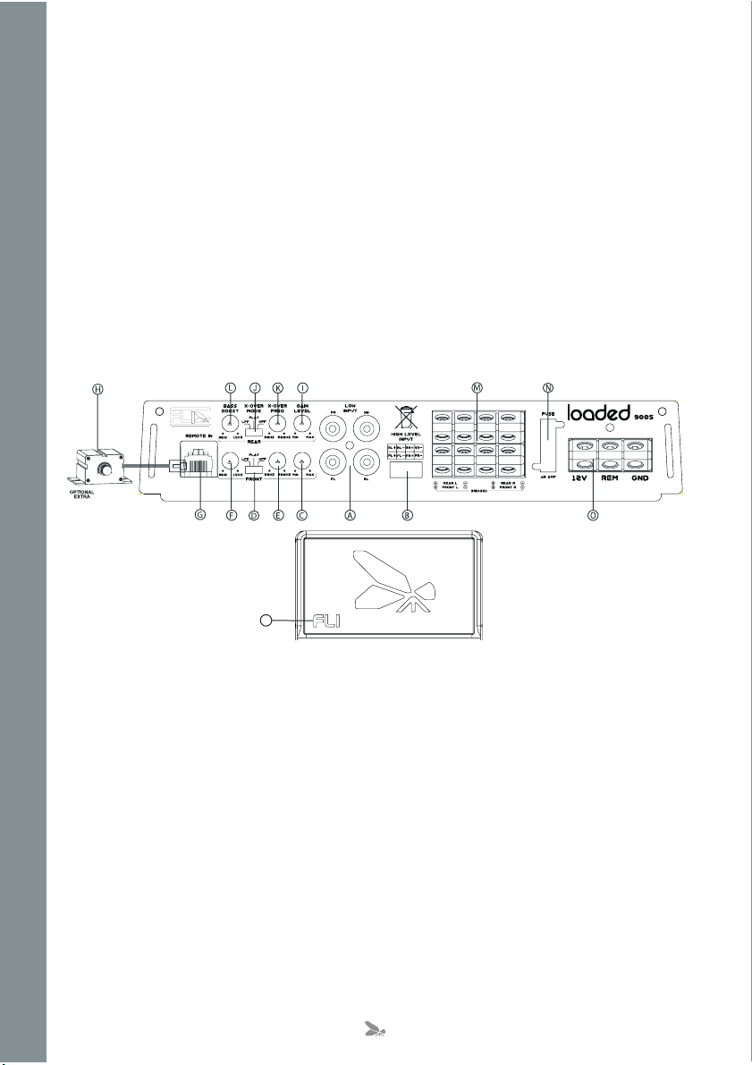
P
A. Low Level Input
For connection to any source (headunit) with a low level output. This is your RCA output from the source (headunit).
B. High Level Input
To be used when no RCA’s are available. Use the provided loom to connect to closest speakers. The loom provided will only
fit one way round. Once plugged in you should connect the wires this way around:
White – Rear Left Speaker Positive
Grey – Rear Left Speaker Negative
Blue – Rear Right Speaker Positive
Green – Rear Right Speaker Negative
Yellow – Front Left Speaker Positive
– Front Left Speaker Negative
Orange
Brown – Front Right Speaker Positive
Black – Front Right Speaker Negative
C. Channel 1 / 2 Gain Control
Used to match the input signal of the source (headunit) to the amplifier. See the setup section for more details.
D. Channel 1 / 2 Cross Over Select Switch
Used to select between Flat, High Pass Filter and Low Pass Filter.
The high pass filter will only allow high frequency information to be passed to the speaker(s) while the low pass filter will only
allow low frequency information to be sent.
If no filter needs to be applied then place
the switch in the flat position.
4
 Loading...